JP2014194231A - Check valve for coolant - Google Patents
Check valve for coolant Download PDFInfo
- Publication number
- JP2014194231A JP2014194231A JP2013070224A JP2013070224A JP2014194231A JP 2014194231 A JP2014194231 A JP 2014194231A JP 2013070224 A JP2013070224 A JP 2013070224A JP 2013070224 A JP2013070224 A JP 2013070224A JP 2014194231 A JP2014194231 A JP 2014194231A
- Authority
- JP
- Japan
- Prior art keywords
- valve
- coolant
- wall surface
- check valve
- elastic member
- Prior art date
- Legal status (The legal status is an assumption and is not a legal conclusion. Google has not performed a legal analysis and makes no representation as to the accuracy of the status listed.)
- Granted
Links
Images


Abstract
Description
中空円筒形状のハウジングと、前記ハウジングと連結するキャップと、前記ハウジング内を摺動するコップ形状のバルブと、前記バルブ内に配置されて上流側からの流体を下流側に流通する流体連通路と、前記バルブの外周壁面と前記流体連通路とが連通する流体連通孔とが備えられ、前記バルブの摺動により前記流体連通路を開閉可能に構成するクーラント用チェックバルブに関するものである。 A hollow cylindrical housing, a cap connected to the housing, a cup-shaped valve that slides in the housing, and a fluid communication path that is disposed in the valve and that circulates fluid from the upstream side to the downstream side The present invention relates to a coolant check valve that is provided with a fluid communication hole through which an outer peripheral wall surface of the valve and the fluid communication path communicate with each other, and is configured to open and close the fluid communication path by sliding the valve.
従来のチェックバルブでは、例えば、図11に示すチェックバルブ200がある。
図11に示す、チェックバルブ200は、中空円筒形状のハウジング201と、ハウジング内を摺動するコップ形状のバルブ202を有する。また、バルブ202内には、上流側からの流体を下流側に流通する流体連通路203が形成され、バルブ202の外周壁面202Aと流体連通路203とが連通する流体連通孔204とが備えられている。また、流体連通路203内にバルブ202を弁座206方向へ付勢する弾性部材205が形成されている。
図11に示すように、チェックバルブ200が開弁状態にあるときには、流体Fは流体連通孔204を介して流体連通路203へと流入する。
As a conventional check valve, for example, there is a
A
As shown in FIG. 11, when the
しかし、従来のチェックバルブには以下のような問題が存在した。
すなわち、図11に示すように流体Fが流体連通路203に流入することにより、流体Fと弾性部材205は接触する。流体Fは切屑・砥粒等の異物を含むクーラント液である場合、弾性部材205に切屑・砥粒等の異物が噛みこむことがある。弾性部材205に切屑・砥粒等の異物が噛みこむことにより、バルブロックが発生する恐れがあるため問題となる。
また、バルブロックが生じないとしても流体連通路203の流速が遅い部分では切屑・砥粒等の異物が集積し全開不良等の問題が生じる恐れがあるため問題となる。
However, the conventional check valve has the following problems.
That is, as shown in FIG. 11, when the fluid F flows into the
Even if the valve block does not occur, foreign matter such as chips and abrasive grains accumulates at a portion where the flow speed of the
本発明は、上記問題点を解決するためになされたものであり、弾性部材を隔離し、弾性部材と切屑・砥粒等が接触することを防止ししたクーラント用チェックバルブを提供することを目的とする。 The present invention has been made to solve the above-described problems, and has an object to provide a check valve for coolant that isolates an elastic member and prevents the elastic member and chips, abrasive grains, etc. from contacting each other. And
上記目的を達成するために、本発明に係るクーラント用チェックバルブは、以下の構成を有する。
(1)中空円筒形状のハウジングと、前記ハウジングと連結するキャップと、前記ハウジング内を摺動するコップ形状のバルブと、前記バルブ内に配置されて上流側からの流体を下流側に流通する流体連通路と、前記バルブの外周壁面と前記流体連通路とが連通する流体連通孔とが備えられ、前記バルブの摺動により前記流体連通路を開閉可能に構成するクーラント用チェックバルブにおいて、前記バルブには、前記外周壁面の全周にわたりツバ部が形成されていること、前記ツバ部に弾性部材の一端部が当接し、前記弾性部材の他端部が前記ハウジング又は前記キャップに当接していること、前記外周壁面と前記ハウジングの内周壁面と前記ツバ部との間に前記弾性部材が形成されていること、を特徴とする。
In order to achieve the above object, a coolant check valve according to the present invention has the following configuration.
(1) A hollow cylindrical housing, a cap connected to the housing, a cup-shaped valve that slides in the housing, and a fluid that is disposed in the valve and circulates fluid from the upstream side to the downstream side A coolant check valve comprising a communication passage, a fluid communication hole that communicates with an outer peripheral wall surface of the valve and the fluid communication passage, and configured to open and close the fluid communication passage by sliding of the valve. The flange portion is formed over the entire circumference of the outer peripheral wall surface, one end portion of the elastic member is in contact with the flange portion, and the other end portion of the elastic member is in contact with the housing or the cap. In addition, the elastic member is formed between the outer peripheral wall surface, the inner peripheral wall surface of the housing, and the flange portion.
それにより、弾性部材は流体連通路と隔離されるため、弾性部材への切屑・砥粒等の異物が噛みこむことを防止することができる。切屑・砥粒等の異物への噛みこみを防止することでバルブロックの発生を防止し、全開不良等の問題の発生の防止をすることができる。 Thereby, since the elastic member is isolated from the fluid communication path, it is possible to prevent foreign matters such as chips and abrasive grains from biting into the elastic member. By preventing biting into foreign matter such as chips and abrasive grains, it is possible to prevent the occurrence of a valve block and prevent problems such as full open failure.
(2)(1)に記載するクーラント用チェックバルブにおいて、前記流体は、切屑・砥粒等の異物を含むクーラント液であること、前記ハウジングの上流に前記異物を止めるフィルタが形成されていること、前記ツバ部の最外周部と前記内周壁面との間のクリアランスが前記フィルタの目開きと同等以下であること、が好ましい。 (2) In the coolant check valve described in (1), the fluid is a coolant liquid containing foreign matter such as chips and abrasive grains, and a filter for stopping the foreign matter is formed upstream of the housing. It is preferable that the clearance between the outermost peripheral portion of the brim portion and the inner peripheral wall surface is equal to or smaller than the opening of the filter.
それにより、フィルタを抜けた切屑・砥粒等の異物がツバ部と内周壁面との間から流れ込むことがない。そのため、弾性部材への切屑・砥粒等の異物が噛みこむことを防止することができる。切屑・砥粒等の異物への噛みこみを防止することでバルブロックの発生を防止し、全開不良等の問題の発生の防止をすることができる。 Thereby, foreign matter such as chips and abrasive grains passing through the filter does not flow from between the flange portion and the inner peripheral wall surface. For this reason, it is possible to prevent foreign matter such as chips and abrasive grains from biting into the elastic member. By preventing biting into foreign matter such as chips and abrasive grains, it is possible to prevent the occurrence of a valve block and prevent problems such as full open failure.
(3)(1)又は(2)に記載するクーラント用チェックバルブにおいて、前記バルブは、前記ツバ部が前記内周壁面と当接する第1ガイドと、前記流体連通路の下流側壁面が前記内周壁面と当接する第2ガイドとを有すること、前記第1ガイドと前記第2ガイドとの間に距離があること、が好ましい。 (3) In the coolant check valve described in (1) or (2), the valve includes a first guide in which the flange portion is in contact with the inner peripheral wall surface, and a downstream side wall surface of the fluid communication path is in the inner side. It is preferable to have a second guide that contacts the peripheral wall surface, and that there is a distance between the first guide and the second guide.
それにより、バルブの平行度を保持することができる。そのため、弁体と弁座のブレを防止することができ、均一に弁体を弁座に当接させることができる。 Thereby, the parallelism of the valve can be maintained. Therefore, blurring of the valve body and the valve seat can be prevented, and the valve body can be uniformly brought into contact with the valve seat.
(4)(1)乃至(3)に記載するいずれか一つのクーラント用チェックバルブにおいて、前記コップ形状の前記バルブの底面にあたる弁体部が前記バルブの中心軸を中心に外周方向にテーパ面が形成されていること、前記テーパ面は前記中心軸に垂直な垂直線に対して10度以上20度以下の傾斜を持つこと、が好ましい。 (4) In any one of the coolant check valves according to (1) to (3), a valve body portion corresponding to a bottom surface of the cup-shaped valve has a tapered surface in an outer peripheral direction around the central axis of the valve. It is preferable that the tapered surface has an inclination of 10 degrees or more and 20 degrees or less with respect to a vertical line perpendicular to the central axis.
それにより、弁体を安定させることができる。すなわち、バルブにテーパ面が形成されていることにより、流路に対して流線形の形状になり流体がバルブ周辺を均一に流れるため弁体を安定させることができる。 Thereby, a valve body can be stabilized. That is, by forming the tapered surface on the valve, the valve body can be stabilized because it has a streamlined shape with respect to the flow path and the fluid flows uniformly around the valve.
(5)(1)乃至(4)に記載するいずれか一つのクーラント用チェックバルブにおいて、前記コップ形状の前記バルブの上面にあたるバルブ端部がテーパ形状であること、が好ましい。 (5) In any one of the coolant check valves described in (1) to (4), it is preferable that a valve end corresponding to an upper surface of the cup-shaped valve has a tapered shape.
それにより、バルブが開弁する時にバルブ端部に集積した切屑・砥粒等の異物を押出すことができる。その理由は、テーパ形状となっていることにより、バルブ端部に集積した切屑・砥粒等の異物をちり取りのようにかき出すことができるからである。かき出した切屑・砥粒等の異物は、そのまま流体連通路の流れにより下流側へと流れる。 Thereby, when the valve is opened, foreign matters such as chips and abrasive grains accumulated at the end of the valve can be pushed out. The reason is that the taper shape allows foreign matter such as chips and abrasive grains accumulated at the end of the valve to be scraped out like dust. Foreign matter, such as scraped chips and abrasive grains, flows to the downstream side as it flows through the fluid communication path.
本発明によれば、弾性部材への切屑・砥粒等の異物が噛みこむことを防止することができ、バルブロックの発生を防止することができる。 ADVANTAGE OF THE INVENTION According to this invention, it can prevent that foreign materials, such as a chip and an abrasive grain, are biting into an elastic member, and generation | occurrence | production of a bullock can be prevented.
次に、本発明に係るクーラント用チェックバルブの一実施の形態について図面を参照して説明する。
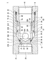
図1に、クーラント用チェックバルブ1(閉弁時)の断面図を示す。図2に、クーラント用チェックバルブ1(開弁時)の断面図を示す。図3に、クーラント用チェックバルブ1(全開開弁時)を流れる流体の方向を示した図である。図4に、図3に示す点線Mで示すクーラント用チェックバルブ1(全開開弁時)を流れる流体の方向を示した拡大図である。図5に、クーラント用チェックバルブ1(70%開弁時)を流れる流体の方向を示した図である。図6に、図5に示す点線Nで示すクーラント用チェックバルブ1(70%開弁時)を流れる流体の方向を示した拡大図である。図7に、クーラント用チェックバルブ1(全開開弁直前時)を流れる流体の方向を示した拡大図である。図8乃至図10に流体連通路35の下流側壁面の拡大図(1)(2)(3)を示す。
Next, an embodiment of a coolant check valve according to the present invention will be described with reference to the drawings.
FIG. 1 shows a cross-sectional view of the coolant check valve 1 (when closed). FIG. 2 shows a cross-sectional view of the coolant check valve 1 (when opened). FIG. 3 is a diagram showing the direction of fluid flowing through the coolant check valve 1 (when fully opened). FIG. 4 is an enlarged view showing the direction of fluid flowing through the coolant check valve 1 (when fully opened) indicated by a dotted line M shown in FIG. FIG. 5 is a diagram showing the direction of fluid flowing through the coolant check valve 1 (70% open). FIG. 6 is an enlarged view showing the direction of fluid flowing through the coolant check valve 1 (70% opened) indicated by a dotted line N shown in FIG. FIG. 7 is an enlarged view showing the direction of the fluid flowing through the coolant check valve 1 (immediately before full opening). 8 to 10 are enlarged views (1), (2), and (3) of the downstream side wall surface of the
<クーラント用チェックバルブの構成>
図1に示すクーラント用チェックバルブ1は、逆止弁である。クーラント用チェックバルブ1内を流れる流体は、例えば切屑・砥粒等の異物を含むクーラント液である。図1に示すように、クーラント用チェックバルブ1は、ハウジング2、バルブ3、及び、キャップ6を有する。
<Configuration of coolant check valve>
The
図1に示すように、ハウジング2は、段付中空円筒形状に形成されている。ハウジング2の内周には、下流端部22から上流端部21に対して、雌ネジ23、摺動壁面部24、流入部25が形成されている。
摺動壁面部24と流入部25の間には絞り部27が形成されており、摺動壁面部24と流入部25を分離している。絞り部27の摺動壁面部24側にバルブ3と当接離間する弁座部26が形成されている。弁座部26は絞り部27の最絞り部27Aから摺動壁面部24の水平部24Aの間に形成されており、最絞り部27Aから水平部24Aにかけて広がる方向にテーパ形状となっている。
As shown in FIG. 1, the
A
キャップ6は中空円筒形状に形成されており、その中心にはキャップ流路61が形成されている。キャップ流路61は流路壁面62により形成されている。キャップ6の外周には雄ネジ63が形成されておりハウジング2の雌ネジ23と螺合する。ハウジング2とキャップ6は、螺合することにより一体となる。キャップ6の外周には段差である弾性部材当接部64が全周にわたり形成されている。弾性部材当接部64は流路壁面62に対して垂直方向に形成されている。また、弾性部材当接部64に、弾性部材7の一端7Aが当接している。
The
図1に示すように、バルブ3は、ハウジング2の内周を摺動する略コップ形状のものである。バルブ3の内周には、流体連通路35が形成されている。流体連通路35の下流側には、開口部が形成されている。また、流体連通路35と外周壁面3Aとが連通する流体連通孔32が形成されている。本実施形態においては、流体連通孔32はバルブ3の全周のうち対抗する位置に合計4か所に形成されている。
As shown in FIG. 1, the
また、バルブ3の全周にわたりツバ部31が形成されている。ツバ部31は外周壁面3Aに対して垂直方向に形成されている。図1に示すように、流体連通孔32の下流端32Aはツバ部31の上流端部31Bと連通している。そのため、流体連通孔32から流体連通路35へと流体が流れやすくなる。
また、ツバ部31は全周にわたり形成されているため、流体の流れを受けやすい。バルブ3が開閉する際に、弁体部3C及びツバ部31が流体を受けるため、低い差圧でもバルブ3が開くことができる。そのため、圧力損失が少ない回路を提供することができる。
A
Moreover, since the
ツバ部31の最外周部31Aは摺動壁面部24と当接している。最外周部31Aと摺動壁面部24が当接している部分を第1ガイドG1とする。図4に示すように、最外周部31Aと摺動壁面部24の当接部分の拡大図においては、隙間Pが形成されている。隙間Pは、クーラント用チェックバルブ1よりも上流に形成されている切屑・砥粒等の異物を取り除くためのフィルタの目開きと同等以下になるように形成されている。隙間Pをフィルタの目開きと同等以下にすることにより、フィルタを抜けた隙間Pよりも大きな切屑・砥粒等の異物がツバ部の最外周部31Aと摺動壁面部24との間から弾性部材室75へと流れ込むことがない。そのため、弾性部材7への切屑・砥粒等の異物が噛みこむことを防止することができる。切屑・砥粒等の異物への噛みこみを防止することでバルブロックの発生を防止することができる。
The outermost
また、ツバ部31の下流端部31Cは弾性部材7の他端7Bと当接している。弾性部材7は、ツバ部31の下流端部31Cと弾性部材当接部64に当接し、その外周をハウジング2により、その内周をバルブ3により囲まれている。弾性部材7が囲まれた領域を弾性部材室75とする。したがって、弾性部材7は弾性部材室75内に収納され、流体連通路35と隔離した状態にあるため、切屑・砥粒等の異物が絡まることがない。
Further, the
バルブ3の外周壁面3Aはキャップ6の流路壁面62に摺動可能な状態で当接している。外周壁面3Aと流路壁面62が当接している部分を第2ガイドG2とする。第1ガイドG1と第2ガイドG2との間に距離があることにより、バルブ3が摺動する際にバルブ3の平行度を保持することができる。そのため、バルブ3と弁座26のブレを防止することができ、均一にバルブ3を弁座26に当接させることができる。
The outer
コップ形状のバルブ3の上面にあたるバルブ端部33には、テーパ形状であるテーパ部33Aが形成されている。テーパ部33Aが形成されていることにより、バルブ3が開弁する時にバルブ端部33に集積した切屑・砥粒等の異物を押出すことができる。具体的には図8に示すように、テーパ部33Aはテーパ形状であるため異物T1が集積する。また、バルブ端部33と流路壁面62の接触面付近は、流体の流れが悪くなるため、異物Tが溜まる溜まり部ができる。そのため、溜まり部には異物T2が集積する。図9に示すようにバルブ3が移動し流路壁面62を摺動することにより、テーパ部33Aの上に集積している異物T1が押し出される。さらに、バルブ端部33が流路壁面62を摺動することにより異物T2をちり取りのようにかき出すことができる。図10に示すように、テーパ部33Aに集積していた異物Tは流体連通路35の流れに乗り下流へと流れる。その結果、異物Tはなくなる。したがって、バルブ端部33にテーパ部33Aが形成されていることにより、異物Tが溜まる溜まりをなくすことができバルブロックを防止することができる。さらに、テーパ部33Aが形成されているため、バルブ3の摺動により自動で切屑・砥粒等の異物を流すことができるセルフクリーン機構を有する。
A
図1に示すように、コップ形状のバルブ3の底面にあたる弁体部3Cがバルブ3の中心軸を中心に外周方向にテーパ面37が形成されている。また、テーパ面37には、Oリング38が形成されている。テーパ面37は中心軸に垂直な垂直線Qに対して角度βを有する。本実施形態において角度βは、10度以上20度以下の傾斜角度とする。10度以上20度以下とすることにより、バルブ3を安定させて摺動させることができる。すなわち、バルブ3にテーパ面37が形成されていることにより、流路に対して流線形の形状になり流体がバルブ3周辺を均一に流れるためバルブ3を安定させることができる。
As shown in FIG. 1, the
<クーラント用チェックバルブの作用・効果>
クーラント用チェックバルブの図1に示す閉弁状態から図2に示す開弁状態に移行する開動作について説明する。
開弁時には、図1に示す状態で、INポートである流入部25のINポート圧をOUTポートであるキャップ流路61のOUTポート圧(弾性部材7の弾性力を含む)よりも高くする。それにより、バルブ3の受圧力がINポートである流入部25方向へ押さえている弾性部材7の弾性力に勝る。そのため、図2に示すように、バルブ3がOUTポートであるキャップ流路61方向へと移動し、弁座26と弁体部3Cとが離間し開弁状態となる。
<Operation and effect of coolant check valve>
The opening operation of the coolant check valve that shifts from the closed state shown in FIG. 1 to the opened state shown in FIG. 2 will be described.
When the valve is opened, in the state shown in FIG. 1, the IN port pressure of the
図3に示すように、クーラント用チェックバルブ1が全開時に、流体Gが流路内を流入部25からキャップ流路61に流れる。図3に示すように、流入部25から流入した流体G1は、弁座26と弁体部3Cの間を抜けて流体連通孔32、流体連通路35を介してキャップ流路61へと流れる。流体は、流体G1、流体G2、流体G3、流体G4の矢印で示す流れが主流となる。
As shown in FIG. 3, when the
図3に示すように、全開時には弾性部材室75には流体の流れがない。その理由は、弾性部材室75は、ツバ部31の下流端部31Cは弾性部材7の他端7Bと当接し、ツバ部31の下流端部31Cと弾性部材当接部64に当接し、その外周をハウジング2により、その内周をバルブ3により囲まれた状態にあるからである。弾性部材室75が囲まれて隔離された状態にあるため、全開時の弾性部材室75内は、完全に流体連通路35と隔離した状態にあるため流体の流れがない。そのため、図3に示すように、弾性部材室75に入り込む可能性のある、流体G2から分流した流体G6は、ツバ部31周辺で流れの向きを変えて主流である流体G2に合流する。
As shown in FIG. 3, there is no fluid flow in the
さらに具体的には、全開時には、図4に示すように、流体G61、G62がツバ部31周辺で流れの向きを変えている。流体G61、G62は、最外周部31Aと摺動壁面部24の間で流れの向きを変えるため、最外周部31Aと摺動壁面部24の間に集積した切屑・砥粒等の異物を流体G62が巻き込んで、主流である流体G2へと流すことができる。切屑・砥粒等の異物を主流である流体G2へと流すことができることにより、弾性部材7へ噛みこむことを防止することができ、バルブロックを防止できる。
More specifically, when fully opened, as shown in FIG. 4, the fluids G <b> 61 and G <b> 62 change the direction of flow around the
さらに、クーラント用チェックバルブ1が全開方向に向かう時には、弾性部材7が縮み、それに伴い弾性部材室75の体積が小さくなる。そのため、図7に示すように、圧縮された弾性部材室75内の流体J51は最外周部31Aと摺動壁面部24の間の隙間Pから押し出され流体J61として主流に合流する。流体J51は隙間Pから流出する際に、最外周部31Aと摺動壁面部24の間に集積した切屑・砥粒等の異物を押し出し主流へと流すことができる。そのため、クーラント用チェックバルブ1は、全開時だけではなく、全開時に向かう時にも、弾性部材7へ噛みこむことを防止することができ、バルブロックを防止できる。なお、図7では、全開直前時を示したが、クーラント用チェックバルブ1のバルブ3が開く方向に移動し、弾性部材室75の体積が小さくなる場合には、弾性部材室75の流体は隙間Pから流出する。そのため、開弁方向に向かう時には、同様の作用効果を得ることができる。
Furthermore, when the
図5に示すようにクーラント用チェックバルブ1が70%開弁時には、流体Hが流路内を流入部25からキャップ流路61に流れる。なお、図3及び図4の流体Gと異なる符号を付けたが、流れる流体は同じである。説明をする際に全開状態と70%開弁状態とで流れる流体の流れ方向が異なるため、表現する符号を変更して記載する。
As shown in FIG. 5, when the
図5に示すように、クーラント用チェックバルブ1が70%開弁時に、流体Hが流路内を流入部25からキャップ流路61に流れる。図5に示すように、流入部25から流入した流体H1は、弁座26と弁体部3Cの間を抜けて流体連通孔32、流体連通路35を介してキャップ流路61へと流れる。流体は、流体H1、流体H2、流体H3、流体H4の矢印で示す流れが主流となる。図5に示す70%開弁時は図3に示す全開状態と主流の流れは同様である。
As shown in FIG. 5, when the
図5に示すように、70%開弁時には主流である流体H2から流体H6が分流し、弾性部材室75には流体H5が流入する。その理由は、70%開弁時には全開時と比較して弾性部材室75の面積が拡大する。そのため、弾性部材室75の拡大した面積に対して流体H6、H5が流入するためである。
As shown in FIG. 5, when the valve is opened by 70%, the fluid H6 is diverted from the mainstream fluid H2, and the fluid H5 flows into the
さらに具体的には、70%開弁時には図6に示すように、バルブ3とキャップ6との間に形成される流路Rから流体H53とする流れがある。70%開弁時には、流体H53の流れに引き込まれ流体H51及び流体52も流路R方向へと流れる。そのため、最外周部31Aと摺動壁面部24の間付近を流れる流体H6は、弾性部材室75方向へと引き込まれる。流体H6が弾性部材室75方向へと流れることにより切屑・砥粒等の異物も流れるが、切屑・砥粒等の異物の大きさはツバ部31の最外周部31Aと摺動壁面部24との間の長さPより大きいため弾性部材室75へと流入することはない。隙間Pより小さな切屑・砥粒等の異物は弾性部材室75へ流れ込むが流路Rからキャップ流路61へ流れ出る。さらに、全開時には図4に示すように、最外周部31Aと摺動壁面部24との間に集積した切屑・砥粒等の異物を流体G62が巻き込んで主流である流体G2へ流すことができ、また、チェックバルブが全開方向に向かうときは図7に示すように、弾性部材室75から流体J51、J61と流れるため、最外周部31Aと摺動壁面部24との間に集積した切屑・砥粒等の異物を主流である流体J2へと流すことができる。
More specifically, when the valve is 70% open, as shown in FIG. 6, there is a flow from the flow path R formed between the
クーラント用チェックバルブの図2に示す開弁状態から図1に示す閉弁状態に移行する閉動作について説明する。
閉弁時には、図2に示す状態で、OUTポートであるキャップ流路61のOUTポート圧(弾性部材7の弾性力を含む)をINポートである流入部25のINポート圧よりも高くする。それにより、弾性部材7の弾性力がOUTポートであるキャップ流路61方向へ押さえているバルブ3の受圧力に勝る。そのため、図1に示すように、バルブ3がINポートである流入部25方向へと移動し、弁座26と弁体部3Cとが当接し閉弁状態となる。
The closing operation of the coolant check valve that shifts from the valve opening state shown in FIG. 2 to the valve closing state shown in FIG. 1 will be described.
When the valve is closed, in the state shown in FIG. 2, the OUT port pressure (including the elastic force of the elastic member 7) of the
<変形例>
尚、本発明は、上記実施の形態に限定されることなく、発明の趣旨を逸脱することのない範囲で色々な応用が可能である。
<Modification>
Note that the present invention is not limited to the above-described embodiment, and various applications are possible without departing from the spirit of the invention.
例えば、上記実施形態においては、流体連通孔32を4か所形成することとしたが、4か所以下、又は4か所以上形成することができる。流体連通孔32の数を増やすと流体の流れが大きくなり、数を減らすと流体の流れが小さくなる。 For example, in the above embodiment, four fluid communication holes 32 are formed, but four or less, or four or more can be formed. Increasing the number of fluid communication holes 32 increases the fluid flow, and decreasing the number decreases the fluid flow.
例えば、上記実施形態において、弾性部材7の他端7Bはキャップ6の弾性部材当接部64と当接することとしたが、ハウジング3の一部と当接させることもできる。
For example, in the above embodiment, the
1 クーラント用チェックバルブ
2 ハウジング
24 内周壁面
3 バルブ
3A 外周壁面
31 ツバ部
32 流体連通孔
35 流体連通路
6 キャップ
7 弾性部材
DESCRIPTION OF
Claims (5)
前記バルブには、前記外周壁面の全周にわたりツバ部が形成されていること、
前記ツバ部に弾性部材の一端部が当接し、前記弾性部材の他端部が前記ハウジング又は前記キャップに当接していること、
前記外周壁面と前記ハウジングの内周壁面と前記ツバ部との間に前記弾性部材が形成されていること、
を特徴とするクーラント用チェックバルブ。 A hollow cylindrical housing, a cap connected to the housing, a cup-shaped valve that slides in the housing, and a fluid communication path that is disposed in the valve and that circulates fluid from the upstream side to the downstream side In the check valve for coolant, comprising a fluid communication hole for communicating the outer peripheral wall surface of the valve and the fluid communication path, and configured to open and close the fluid communication path by sliding the valve,
In the valve, a flange portion is formed over the entire circumference of the outer peripheral wall surface,
One end portion of the elastic member is in contact with the collar portion, and the other end portion of the elastic member is in contact with the housing or the cap;
The elastic member is formed between the outer peripheral wall surface, the inner peripheral wall surface of the housing, and the flange portion;
Check valve for coolant.
前記流体は、切屑・砥粒等の異物を含むクーラント液であること、
前記ハウジングの上流に前記異物を止めるフィルタが形成されていること、
前記ツバ部の最外周部と前記内周壁面との間のクリアランスが前記フィルタの目開きと同等以下であること、
を特徴とするクーラント用チェックバルブ。 The coolant check valve according to claim 1,
The fluid is a coolant liquid containing foreign matter such as chips and abrasive grains,
A filter for stopping the foreign matter is formed upstream of the housing;
The clearance between the outermost peripheral portion of the flange portion and the inner peripheral wall surface is equal to or less than the opening of the filter,
Check valve for coolant.
前記バルブは、前記ツバ部が前記内周壁面と当接する第1ガイドと、前記流体連通路の下流側壁面が前記内周壁面と当接する第2ガイドとを有すること、
前記第1ガイドと前記第2ガイドとの間に距離があること、
を特徴とするクーラント用チェックバルブ。 In the coolant check valve according to claim 1 or 2,
The valve includes a first guide in which the flange portion comes into contact with the inner peripheral wall surface, and a second guide in which a downstream side wall surface of the fluid communication path comes into contact with the inner peripheral wall surface,
There is a distance between the first guide and the second guide;
Check valve for coolant.
前記コップ形状の前記バルブの底面にあたる弁体部が前記バルブの中心軸を中心に外周方向にテーパ面が形成されていること、
前記テーパ面は前記中心軸に垂直な垂直線に対して10度以上20度以下の傾斜を持つこと、
を特徴とするクーラント用チェックバルブ。 The coolant check valve according to any one of claims 1 to 3,
The valve body portion corresponding to the bottom surface of the cup-shaped valve is formed with a tapered surface in the outer peripheral direction around the central axis of the valve;
The tapered surface has an inclination of 10 degrees or more and 20 degrees or less with respect to a vertical line perpendicular to the central axis;
Check valve for coolant.
前記コップ形状の前記バルブの上面にあたるバルブ端部がテーパ形状であること、
を特徴とするクーラント用チェックバルブ。
The coolant check valve according to any one of claims 1 to 4,
The valve end corresponding to the upper surface of the cup-shaped valve is tapered;
Check valve for coolant.
Priority Applications (1)
| Application Number | Priority Date | Filing Date | Title |
|---|---|---|---|
| JP2013070224A JP5948273B2 (en) | 2013-03-28 | 2013-03-28 | Check valve for coolant |
Applications Claiming Priority (1)
| Application Number | Priority Date | Filing Date | Title |
|---|---|---|---|
| JP2013070224A JP5948273B2 (en) | 2013-03-28 | 2013-03-28 | Check valve for coolant |
Publications (2)
| Publication Number | Publication Date |
|---|---|
| JP2014194231A true JP2014194231A (en) | 2014-10-09 |
| JP5948273B2 JP5948273B2 (en) | 2016-07-06 |
Family
ID=51839604
Family Applications (1)
| Application Number | Title | Priority Date | Filing Date |
|---|---|---|---|
| JP2013070224A Active JP5948273B2 (en) | 2013-03-28 | 2013-03-28 | Check valve for coolant |
Country Status (1)
| Country | Link |
|---|---|
| JP (1) | JP5948273B2 (en) |
Cited By (5)
| Publication number | Priority date | Publication date | Assignee | Title |
|---|---|---|---|---|
| JP2016176482A (en) * | 2015-03-18 | 2016-10-06 | 株式会社デンソー | Fluid control valve and high-pressure pump |
| JP2017115983A (en) * | 2015-12-24 | 2017-06-29 | 株式会社豊田自動織機 | Compressor |
| JP2019510942A (en) * | 2016-03-24 | 2019-04-18 | オーリンス・レイシング・エービーOehlins Racing Ab | Check valve assembly |
| CN110657265A (en) * | 2018-06-29 | 2020-01-07 | 浙江三花汽车零部件有限公司 | One-way valve |
| WO2022234928A1 (en) * | 2021-05-04 | 2022-11-10 | 남양넥스모 주식회사 | Receptacle check valve for refueling hydrogen |
Citations (4)
| Publication number | Priority date | Publication date | Assignee | Title |
|---|---|---|---|---|
| JPS56102865U (en) * | 1980-01-09 | 1981-08-12 | ||
| JPS6228975U (en) * | 1985-08-05 | 1987-02-21 | ||
| JPH07293719A (en) * | 1994-04-21 | 1995-11-10 | Toyo Umpanki Co Ltd | Check valve |
| JP2010188466A (en) * | 2009-02-18 | 2010-09-02 | Sumitomo Precision Prod Co Ltd | Coolant supplying device |
-
2013
- 2013-03-28 JP JP2013070224A patent/JP5948273B2/en active Active
Patent Citations (4)
| Publication number | Priority date | Publication date | Assignee | Title |
|---|---|---|---|---|
| JPS56102865U (en) * | 1980-01-09 | 1981-08-12 | ||
| JPS6228975U (en) * | 1985-08-05 | 1987-02-21 | ||
| JPH07293719A (en) * | 1994-04-21 | 1995-11-10 | Toyo Umpanki Co Ltd | Check valve |
| JP2010188466A (en) * | 2009-02-18 | 2010-09-02 | Sumitomo Precision Prod Co Ltd | Coolant supplying device |
Cited By (7)
| Publication number | Priority date | Publication date | Assignee | Title |
|---|---|---|---|---|
| JP2016176482A (en) * | 2015-03-18 | 2016-10-06 | 株式会社デンソー | Fluid control valve and high-pressure pump |
| JP2017115983A (en) * | 2015-12-24 | 2017-06-29 | 株式会社豊田自動織機 | Compressor |
| JP2019510942A (en) * | 2016-03-24 | 2019-04-18 | オーリンス・レイシング・エービーOehlins Racing Ab | Check valve assembly |
| CN110657265A (en) * | 2018-06-29 | 2020-01-07 | 浙江三花汽车零部件有限公司 | One-way valve |
| WO2022234928A1 (en) * | 2021-05-04 | 2022-11-10 | 남양넥스모 주식회사 | Receptacle check valve for refueling hydrogen |
| KR20220150518A (en) * | 2021-05-04 | 2022-11-11 | 남양넥스모 주식회사 | Receptacle check valve for refueling hydrogen |
| KR102651683B1 (en) * | 2021-05-04 | 2024-03-28 | 남양넥스모 주식회사 | Receptacle check valve for refueling hydrogen |
Also Published As
| Publication number | Publication date |
|---|---|
| JP5948273B2 (en) | 2016-07-06 |
Similar Documents
| Publication | Publication Date | Title |
|---|---|---|
| JP5948273B2 (en) | Check valve for coolant | |
| US10738894B2 (en) | Valve mechanism for removing foreign matter at valve port | |
| US7875171B2 (en) | Suction filter for an automatic transmission | |
| US9903488B2 (en) | Control valve | |
| US8205636B2 (en) | Flow rate control valve | |
| US20180117511A1 (en) | Element assembly and filter | |
| CN105042095A (en) | Flow path velocity modifier for a control valve | |
| EP3026312A1 (en) | Control valve | |
| JP6492579B2 (en) | Negative pressure release valve | |
| JP5369065B2 (en) | Three-way valve | |
| CN108626404A (en) | Valve with whole machine balancing access | |
| KR20050118724A (en) | Backflow preventer | |
| JP2008232196A (en) | Constant flow rate controller | |
| JP5575590B2 (en) | Pressure reducing valve | |
| US9920835B2 (en) | Piston device and pressure regulator using same | |
| EP3214350A2 (en) | Thermostatic tap for liquid fluids | |
| JP2013079692A (en) | Flow rate control valve | |
| EP3502532B1 (en) | Valve | |
| US20200386337A1 (en) | Vale of a hydraulic circuit with constant pressure drop | |
| JP6425451B2 (en) | Check valve | |
| CN114321452A (en) | Valve assembly | |
| CN104006194A (en) | Reducing valve | |
| CN103252151B (en) | Filtering device and corresponding vacuum adjusting device | |
| KR101403994B1 (en) | Pressure reducing valve | |
| JP2006046409A (en) | Check valve |
Legal Events
| Date | Code | Title | Description |
|---|---|---|---|
| A621 | Written request for application examination |
Free format text: JAPANESE INTERMEDIATE CODE: A621 Effective date: 20141022 |
|
| A131 | Notification of reasons for refusal |
Free format text: JAPANESE INTERMEDIATE CODE: A131 Effective date: 20151006 |
|
| A521 | Written amendment |
Free format text: JAPANESE INTERMEDIATE CODE: A523 Effective date: 20151110 |
|
| TRDD | Decision of grant or rejection written | ||
| A01 | Written decision to grant a patent or to grant a registration (utility model) |
Free format text: JAPANESE INTERMEDIATE CODE: A01 Effective date: 20160531 |
|
| A61 | First payment of annual fees (during grant procedure) |
Free format text: JAPANESE INTERMEDIATE CODE: A61 Effective date: 20160606 |
|
| R150 | Certificate of patent or registration of utility model |
Ref document number: 5948273 Country of ref document: JP Free format text: JAPANESE INTERMEDIATE CODE: R150 |