US9920835B2 - Piston device and pressure regulator using same - Google Patents
Piston device and pressure regulator using same Download PDFInfo
- Publication number
- US9920835B2 US9920835B2 US14/764,118 US201414764118A US9920835B2 US 9920835 B2 US9920835 B2 US 9920835B2 US 201414764118 A US201414764118 A US 201414764118A US 9920835 B2 US9920835 B2 US 9920835B2
- Authority
- US
- United States
- Prior art keywords
- baffle plate
- pressure regulator
- piston device
- piston
- piston body
- Prior art date
- Legal status (The legal status is an assumption and is not a legal conclusion. Google has not performed a legal analysis and makes no representation as to the accuracy of the status listed.)
- Active
Links
Images


Classifications
-
- F—MECHANICAL ENGINEERING; LIGHTING; HEATING; WEAPONS; BLASTING
- F16—ENGINEERING ELEMENTS AND UNITS; GENERAL MEASURES FOR PRODUCING AND MAINTAINING EFFECTIVE FUNCTIONING OF MACHINES OR INSTALLATIONS; THERMAL INSULATION IN GENERAL
- F16K—VALVES; TAPS; COCKS; ACTUATING-FLOATS; DEVICES FOR VENTING OR AERATING
- F16K1/00—Lift valves or globe valves, i.e. cut-off apparatus with closure members having at least a component of their opening and closing motion perpendicular to the closing faces
- F16K1/32—Details
-
- F—MECHANICAL ENGINEERING; LIGHTING; HEATING; WEAPONS; BLASTING
- F16—ENGINEERING ELEMENTS AND UNITS; GENERAL MEASURES FOR PRODUCING AND MAINTAINING EFFECTIVE FUNCTIONING OF MACHINES OR INSTALLATIONS; THERMAL INSULATION IN GENERAL
- F16J—PISTONS; CYLINDERS; SEALINGS
- F16J1/00—Pistons; Trunk pistons; Plungers
- F16J1/09—Pistons; Trunk pistons; Plungers with means for guiding fluids
-
- F—MECHANICAL ENGINEERING; LIGHTING; HEATING; WEAPONS; BLASTING
- F16—ENGINEERING ELEMENTS AND UNITS; GENERAL MEASURES FOR PRODUCING AND MAINTAINING EFFECTIVE FUNCTIONING OF MACHINES OR INSTALLATIONS; THERMAL INSULATION IN GENERAL
- F16J—PISTONS; CYLINDERS; SEALINGS
- F16J1/00—Pistons; Trunk pistons; Plungers
- F16J1/10—Connection to driving members
- F16J1/12—Connection to driving members with piston-rods, e.g. rigid connections
-
- F—MECHANICAL ENGINEERING; LIGHTING; HEATING; WEAPONS; BLASTING
- F16—ENGINEERING ELEMENTS AND UNITS; GENERAL MEASURES FOR PRODUCING AND MAINTAINING EFFECTIVE FUNCTIONING OF MACHINES OR INSTALLATIONS; THERMAL INSULATION IN GENERAL
- F16K—VALVES; TAPS; COCKS; ACTUATING-FLOATS; DEVICES FOR VENTING OR AERATING
- F16K1/00—Lift valves or globe valves, i.e. cut-off apparatus with closure members having at least a component of their opening and closing motion perpendicular to the closing faces
- F16K1/32—Details
- F16K1/34—Cutting-off parts, e.g. valve members, seats
- F16K1/36—Valve members
-
- F—MECHANICAL ENGINEERING; LIGHTING; HEATING; WEAPONS; BLASTING
- F16—ENGINEERING ELEMENTS AND UNITS; GENERAL MEASURES FOR PRODUCING AND MAINTAINING EFFECTIVE FUNCTIONING OF MACHINES OR INSTALLATIONS; THERMAL INSULATION IN GENERAL
- F16K—VALVES; TAPS; COCKS; ACTUATING-FLOATS; DEVICES FOR VENTING OR AERATING
- F16K1/00—Lift valves or globe valves, i.e. cut-off apparatus with closure members having at least a component of their opening and closing motion perpendicular to the closing faces
- F16K1/32—Details
- F16K1/48—Attaching valve members to screw-spindles
- F16K1/487—Attaching valve members to screw-spindles by a fixing element extending in the axial direction of the spindle, e.g. a screw
Definitions
- the present disclosure relates to a piston device and a pressure regulator using the same.
- a piston device can be used for controlling and regulating pressure of an outlet by having one end of the piston device connected with and driven by a valve rod.
- a valve port 300 is arranged between an inlet 100 and an outlet 200 , one end of a valve rod 110 is connected with a piston device 120 , and the valve rod 110 drives the piston device 120 to move up and down to control the opening and closing of the valve port 300 so as to adjust the pressure of the outlet 200 .
- an engineer arranges a perforated baffle plate 130 at the top of the piston device 120 , such that a medium coming from the inlet 100 flows into the piston device 120 via the baffle plate 130 ; thus, the pressure on the upper surface of the baffle plate 130 is equal to the pressure on the lower surface of the baffle plate.
- a design is, however, only based on the hypothesis of a static medium.
- the fluid flow state of the area A is very unstable, such that the baffle plate 130 is subjected to an unstable force, thereby influencing the stability of the supply of the medium at a downstream outlet 200 .
- the flow speed of the medium inside the cavity is very low, and as the speed is inversely proportional to the pressure, i.e., the pressure is small if the speed is high and the pressure is large if the speed is low, the pressure under the baffle plate 130 is larger than the pressure on the upper surface of the baffle plate 130 .
- the stresses on the upper and lower parts of the piston device are unbalanced, which influences the stability of the supply of the medium downstream as well.
- the invention provides a piston device that can improve the stress conditions on and under a baffle plate of the piston device and improve the stability of the whole system when a fluid medium flows via the piston device.
- a piston device in accordance with a first exemplary aspect of the present invention, includes a piston body and a baffle plate having openings.
- the baffle plate is arranged in the piston body, and divides the piston body into an upper first area and a lower second area.
- the distance between the baffle plate and an upper end part of the piston body is larger than or equal to 3 mm.
- the distance between the baffle plate and the upper end part of the piston body is between 4 mm and 35 mm.
- the distance between the baffle plate and the upper end part of the piston body is 5, 10, 15, 20, 25 or 30 mm.
- the piston body is also provided with a closing element, and the distance between the baffle plate and the upper end part of the piston body comprises to the distance between the baffle plate and the closing element.
- the closing element of the piston body can be a cutting edge, rubber part, or metal end surface.
- a positioning sleeve is arranged outside the piston body, and seal rings are arranged between the positioning sleeve and the piston body.
- the seal rings are O-shaped, Y-shaped or starlike.
- a guide belt arranged between the positioning sleeve and the piston body.
- piston body and the baffle plate are threadingly coupled to one another.
- fluid medium flowing via the piston device can enter the first area of the piston and enter the second area via the perforated baffle plate, and the fluid medium is buffered in the first area, so that the fluid medium is balanced between the first area and the second area.
- the distance between the baffle plate and the upper end part of the piston body is larger than or equal to 3 mm; in turn, the system performance of the whole piston device tends to be stable. More particularly, when the distance between the baffle plate and the upper end part of the piston body is equal to 4, 5, 10, 15, 20, 25, or 30 mm, the system performance is the best.
- the piston body is also provided with a closing element to help to realize a better sealing effect between the piston device and a valve port.
- the distance between the baffle plate and the upper end part of the piston body refers to the distance between the baffle plate and the closing element.
- the closing element can be a cutting edge, a rubber part, or a metal end surface.
- the distance between the baffle plate and the upper end part of the piston body refers to the distance between the baffle plate and the cutting edge.
- the distance between the baffle plate and the upper end part of the piston body refers to the distance between the baffle plate and the rubber part.
- the distance between the baffle plate and the upper end part of the piston body refers to the distance between the baffle plate and the metal end surface.
- a positioning sleeve is arranged outside the piston body, so the piston device can be tightly wrapped, thereby preventing radial displacement of the piston device when moved up and down.
- seal rings are arranged between the positioning sleeve and the piston body.
- a pressure regulator using the piston device is closed, and in this position, the seal rings between the positioning sleeve and the piston body achieve a sealing effect, preventing the medium from the inlet from entering the outlet side.
- a guide belt is arranged between the positioning sleeve and the piston body.
- the piston device is further wrapped in the positioning sleeve, and the guide belt serves to guide and lubricate the piston body.
- the piston body and the baffle plate can be separately formed and conveniently detachably connected.
- the baffle plate can be threadingly connected to the piston body.
- piston body and the baffle plate can be integrally formed with one another.
- a pressure regulator in accordance with a second exemplary aspect of the present invention, includes the abovementioned piston device as well as an inlet, an outlet, a valve port arranged between the inlet and the outlet, and a valve rod One end of the valve rod is connected with the piston device, and the valve rod drives the piston device to move up and down to control the opening and closing of the valve port, thereby controlling the pressure of a medium flowing from the inletto the outlet.
- the pressure regulator further includes a sealing rubber, a cutting edge, or a metal end surface arranged at one surface of the valve port opposite the piston device.
- one end of the valve rod is in threaded connection with the baffle plate.
- the piston body includes a closing element, which can take the form of a cutting edge, a rubber part, or a metal end surface.
- a closing element which can take the form of a cutting edge, a rubber part, or a metal end surface.
- the closing element of the piston device is the cutting edge or metal end surface
- one surface of the valve port opposite to the piston device is provided with the sealing rubber.
- the closing element of the piston device is the sealing rubber
- one surface of the valve port opposite to the piston device is provided with the cutting edge or metal end surface.
- the closing element of the piston device is the metal end surface
- the valve port is provided with the metal end surface or sealing rubber corresponding to the metal end surface.
- FIG. 1 is a schematic diagram of a piston device used in a conventional pressure regulator.
- FIG. 2 is a schematic diagram of one exemplary embodiment of a piston device constructed in accordance with the teachings of the present invention.
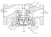
- FIG. 3 is a schematic diagram of one exemplary embodiment of a pressure regulator constructed in accordance with the teachings of the present invention.
- FIG. 4 depicts a ratio of the height to diameter of a baffle plate of the piston device of FIG. 2 .
- FIG. 5 is aschematic diagram of system pressure detection of the piston device of FIG. 2 in the pressure regulator of FIG. 3 .
- FIG. 6 is another schematic diagram of system pressure detection of the piston device of FIG. 2 in the pressure regulator of FIG. 3 .
- a piston device 215 is provided.
- the piston device 215 comprises a piston body 220 and a baffle plate 230 having a surface provided with openings 232 .
- the baffle plate 230 is arranged in the piston body 220 and divides the piston body 220 into an upper first area C and a lower second area B.
- the distance between the baffle plate 230 and an upper end part 234 of the piston body 220 is larger than or equal to 3 mm, namely, the height of the first area C is larger than or equal to 3 mm, the relationship between the input and output pressure of the fluid medium flowing through the piston device 215 tends to be stable.
- the distance between the baffle plate 230 and the upper end part 234 of the piston body 220 is between 4 and 35 mm, the relationship between the input and output pressure of the fluid medium flowing through the piston device 215 is even more stable.
- the distance between the baffle plate 230 and the upper end part 234 of the piston body is 5, 10, 15, 20 or 25 mm, the whole system is the most stable.
- the piston device 215 further includes a closing element arranged at the upper end part 234 of the piston body 220 .
- the closing element is matched with a valve port outside the piston device 215 for operational use.
- the closing element can be a cutting edge 280 or metal end surface, with the valve port provided with sealing rubber matched with the cutting edge 280 or metal end surface.
- the cutting edge 280 or metal end surface can be directly cut into the sealing rubber to further enhance the sealing effect.
- the closing element can also be a rubber part, with the valve port provided with a cutting edge or metal end surface matched with the rubber part.
- the valve port is also provided with a metal end surface corresponding to and matched with the metal end surface for operational use.
- the distance between the baffle plate 230 and the upper end part 234 of the piston body 220 refers to the distance between the baffle plate 230 and the closing element.
- a positioning sleeve 270 can be arranged outside the piston body 220 .
- the positioning sleeve 270 can tightly wrap the piston device, so that the piston device 215 does not radially displace when moving up and down.
- the piston body 220 and the baffle plate 230 can be separately formed and connected, thereby enabling a convenient detachment, or can be integrally formed, so as to ensure the stability of the system.
- Seal rings 240 and 250 are arranged between the positioning sleeve 270 and the piston body 220 , such that when the piston device 215 contacts with the outer valve port, the seal rings 240 and 250 can prevent inlet pressure from entering the outlet side.
- the seal rings 240 , 250 can be O-shaped, Y-shaped or starlike.
- a guide belt 260 is arranged between the positioning sleeve 270 and the piston body 220 .
- the piston device 215 is further wrapped in the positioning sleeve 270 , thus guiding and lubricating effects are achieved.
- a pressure regulator 375 is provided. As shown in FIG. 3 , of the pressure regulator 375 includes the piston device 215 described in connection with the Embodiment I; details regarding the piston device 215 are not repeated herein. As also shown in FIG. 3 , the pressure regulator 375 further includes an inlet 400 , an outlet 500 , a valve port 600 , and a valve rod 310 . The valve port 600 is arranged between the inlet 400 and the outlet 500 , and a third area A is formed between the valve port 600 and the outlet 500 .
- One end 312 of the valve rod 310 is connected to the piston device 215 , such that the valve rod 310 drives the piston device to move up and down to control the opening and closing of the valve port 600 , and thus control the pressure of a medium, which enters from the inlet 400 and flows out of the outlet 500 .
- the one end 312 of the valve rod 310 is in threaded connection with the baffle plate 230 , which allows the pressure regulator 375 to be conveniently detached.
- the fluid medium flows via the third area A from the inlet 400 , flows out from the outlet 500 , and simultaneously enters the first area C and the second area B of the piston device.
- pressures on the upper and lower parts of the piston device 215 tend to be consistent, thereby reducing the unbalanced pressure that would otherwise be present on the upper and lower parts of the piston device 215 .
- the pressure of the fluid medium flowing out at the outlet 500 tends to be stable.
- the pressure in the whole pressure regulator tends to be stable.
- the supplying pressure of the medium at the downstream outlet 500 tends to be stable.
- the pressure regulator 375 further comprises sealing rubber 390 arranged on the valve port 600 .
- the piston device 215 is provided with a cutting edge 380 , and when the piston device gets close to the valve port, the cutting edge 380 is cut into the sealing rubber 390 to enhance of the seal between the piston device 215 and the valve port 600 .
- the closing element of the piston device 215 can be sealing rubber, in which case the valve port 600 is provided with a cutting edge or metal end surface.
- system pressure detection data of the pressure regulator 375 are listed as follows:
- FIG. 4 is a diagram of the ratio of the height to diameter of the baffle plate 230 of the piston device 215 , wherein F is the diameter of the piston device 215 and E is the distance between the baffle plate 230 and the upper end part 234 of the piston device 215 .
- F is the diameter of the piston device 215
- E is the distance between the baffle plate 230 and the upper end part 234 of the piston device 215 .
- FIG. 5 is a schematic diagram of system pressure detection of the piston device 215 in the pressure regulator 375 .
- the pressure of the inlet 400 is 30 bar
- the pressure of the outlet 500 is controlled at 2.5 bar
- FIG. 5 shows that when the distance between the baffle plate 230 and the upper end part 234 of the piston device 215 is larger than 3 mm and smaller than 38 mm, the whole system pressure tends to be in a stable state.
- the distance is between 4 mm and 31 mm, the upper and lower fluctuation of a system pressure curve is the most stable.
- the distance is 10 mm ⁇ 2 mm, 15 mm, and 27 mm ⁇ 2 mm, the system pressure curve is consistent.
- FIG. 6 is another schematic diagram of system pressure detection of the piston device 215 in the pressure regulator 375 .
- the pressure of the inlet 400 is 3 bar
- the pressure of the outlet 500 is controlled at 2.5 bar
- FIG. 6 shows that when the distance between the baffle plate 230 and the upper end part 234 of the piston device 215 is larger than 3 mm and smaller than 38 mm, the whole system pressure tends to be in a stable state, and when the distance is 4, 5, 10, 15, 20, 25, 30, or 35 mm, the pressure curve is stable.
- the fluid medium can enter the first area C and the second area B of the piston device from the inlet 400 , and pressures of the inlet 400 , the piston device 215 , and the sleeve 270 can be relieved as well and the system burden of the whole pressure regulator 375 is reduced.
- the pressure regulator 375 also has the advantages of the piston device 215 described in connection with Embodiment I. Wherein, no matter whether the piston device 215 is close to or away from the valve port 600 , seal rings 340 and 350 can seal the medium in the first area C and the second area B, and the medium cannot flow to the downstream outlet 500 .
- the seal rings 340 , 350 can be O-shaped, Y-shaped or starlike.
- the pressure regulator 375 can regulate both liquid mediums and gas mediums.
Landscapes
- Engineering & Computer Science (AREA)
- General Engineering & Computer Science (AREA)
- Mechanical Engineering (AREA)
- Chemical & Material Sciences (AREA)
- Combustion & Propulsion (AREA)
- Control Of Fluid Pressure (AREA)
Abstract
Description
Claims (11)
Applications Claiming Priority (7)
| Application Number | Priority Date | Filing Date | Title |
|---|---|---|---|
| CN201320076547U | 2013-01-28 | ||
| CN201320076547.0 | 2013-01-28 | ||
| CN201310051398 | 2013-01-28 | ||
| CN 201320076547 CN203131058U (en) | 2013-01-28 | 2013-01-28 | Piston device and pressure regulator using same |
| CN201310051398.7 | 2013-01-28 | ||
| CN201310051398.7A CN103968091A (en) | 2013-01-28 | 2013-01-28 | Piston device and pressure regulator using same |
| PCT/CN2014/071302 WO2014114256A1 (en) | 2013-01-28 | 2014-01-24 | Piston device and pressure regulator using same |
Publications (2)
| Publication Number | Publication Date |
|---|---|
| US20150362070A1 US20150362070A1 (en) | 2015-12-17 |
| US9920835B2 true US9920835B2 (en) | 2018-03-20 |
Family
ID=51226943
Family Applications (1)
| Application Number | Title | Priority Date | Filing Date |
|---|---|---|---|
| US14/764,118 Active US9920835B2 (en) | 2013-01-28 | 2014-01-24 | Piston device and pressure regulator using same |
Country Status (3)
| Country | Link |
|---|---|
| US (1) | US9920835B2 (en) |
| RU (1) | RU2661997C2 (en) |
| WO (1) | WO2014114256A1 (en) |
Families Citing this family (2)
| Publication number | Priority date | Publication date | Assignee | Title |
|---|---|---|---|---|
| RU2661997C2 (en) * | 2013-01-28 | 2018-07-23 | Эмерсон Процесс Менеджмент Регьюлэйтор Текнолоджиз, Инк. | Piston device and pressure regulator using same |
| US10323770B2 (en) * | 2015-10-12 | 2019-06-18 | Emerson Process Management Regulator Technologies, Inc. | Control member for a fluid control device |
Citations (24)
| Publication number | Priority date | Publication date | Assignee | Title |
|---|---|---|---|---|
| US2886283A (en) * | 1958-01-30 | 1959-05-12 | Acf Ind Inc | Seat and seal |
| US3519245A (en) * | 1968-08-23 | 1970-07-07 | Westinghouse Electric Corp | Valve structure |
| US3834666A (en) * | 1972-10-02 | 1974-09-10 | Masoneilan Int Inc | Control valve with elastically loaded cage trim |
| US3892384A (en) * | 1974-04-12 | 1975-07-01 | Honeywell Inc | Double seated cage valve with flexible plug seat |
| US4235413A (en) * | 1978-06-07 | 1980-11-25 | Baker William E | Electrically actuated valve |
| JPH08109972A (en) | 1994-10-11 | 1996-04-30 | Mitsubishi Heavy Ind Ltd | Shock absorber for valve |
| US6095490A (en) | 1997-07-25 | 2000-08-01 | Denso Corporation | Flow control valve for reducing valve leakage |
| US6102366A (en) * | 1997-09-04 | 2000-08-15 | Perez C.; Sergio | Balanced valve operated by the axial driving of a stem displacing a special elastomeric sealing body |
| US20020017327A1 (en) * | 2000-07-28 | 2002-02-14 | Shigehiro Kawaai | Single seat valve apparatus |
| US6394135B2 (en) * | 1999-05-18 | 2002-05-28 | Barber-Colman | Balanced plug valve with contour wall |
| JP2004019918A (en) | 2002-06-20 | 2004-01-22 | Toshiba Corp | Valve device and method of manufacturing the same |
| US20050000577A1 (en) * | 2003-07-03 | 2005-01-06 | Alman Paul T. | Multiple material valve plug for high temperature operation |
| CN201236952Y (en) | 2008-01-25 | 2009-05-13 | 上海富地阀门有限公司 | Liquid-gas pressure break valve |
| CN201539579U (en) | 2009-11-23 | 2010-08-04 | 上海富地阀门有限公司 | Improved liquid-gas pressure self-balancing stop valve |
| CN101858440A (en) | 2010-06-18 | 2010-10-13 | 陈国顺 | Two-way electromagnetic valve |
| US7832426B2 (en) * | 2006-09-05 | 2010-11-16 | Fisher Controls International Llc | Parabolic bonnet for three-way valve |
| CN102392911A (en) | 2011-11-15 | 2012-03-28 | 浙江迎日阀门制造有限公司 | Diaphragm type pressure reducing valve |
| CN102777645A (en) | 2011-10-31 | 2012-11-14 | 费希尔久安输配设备(成都)有限公司 | Flow adjuster, valve and trim assembly |
| US8356622B2 (en) * | 2009-06-08 | 2013-01-22 | Fisher Control International, LLC | Fluid valves having dynamic valve trim joints |
| CN203131058U (en) | 2013-01-28 | 2013-08-14 | 费希尔久安输配设备(成都)有限公司 | Piston device and pressure regulator using same |
| US20130320252A1 (en) * | 2011-02-17 | 2013-12-05 | Egc Enterprises, Inc. | Control valve assembly |
| US8820708B2 (en) * | 2009-07-17 | 2014-09-02 | Fisher Controls International Llc | Seal assemblies for use with fluid valves |
| US9022070B2 (en) * | 2012-07-16 | 2015-05-05 | Fisher Controls International Llc | Bolted valve control element |
| US20150362070A1 (en) * | 2013-01-28 | 2015-12-17 | Emerson Process Management Regulator Technologies, Inc. | Piston Device and Pressure Regulator Using Same |
-
2014
- 2014-01-24 RU RU2015136062A patent/RU2661997C2/en active
- 2014-01-24 WO PCT/CN2014/071302 patent/WO2014114256A1/en not_active Ceased
- 2014-01-24 US US14/764,118 patent/US9920835B2/en active Active
Patent Citations (25)
| Publication number | Priority date | Publication date | Assignee | Title |
|---|---|---|---|---|
| US2886283A (en) * | 1958-01-30 | 1959-05-12 | Acf Ind Inc | Seat and seal |
| US3519245A (en) * | 1968-08-23 | 1970-07-07 | Westinghouse Electric Corp | Valve structure |
| US3834666A (en) * | 1972-10-02 | 1974-09-10 | Masoneilan Int Inc | Control valve with elastically loaded cage trim |
| US3892384A (en) * | 1974-04-12 | 1975-07-01 | Honeywell Inc | Double seated cage valve with flexible plug seat |
| US4235413A (en) * | 1978-06-07 | 1980-11-25 | Baker William E | Electrically actuated valve |
| JPH08109972A (en) | 1994-10-11 | 1996-04-30 | Mitsubishi Heavy Ind Ltd | Shock absorber for valve |
| US6095490A (en) | 1997-07-25 | 2000-08-01 | Denso Corporation | Flow control valve for reducing valve leakage |
| US6102366A (en) * | 1997-09-04 | 2000-08-15 | Perez C.; Sergio | Balanced valve operated by the axial driving of a stem displacing a special elastomeric sealing body |
| US6394135B2 (en) * | 1999-05-18 | 2002-05-28 | Barber-Colman | Balanced plug valve with contour wall |
| US20020017327A1 (en) * | 2000-07-28 | 2002-02-14 | Shigehiro Kawaai | Single seat valve apparatus |
| JP2004019918A (en) | 2002-06-20 | 2004-01-22 | Toshiba Corp | Valve device and method of manufacturing the same |
| US6997211B2 (en) * | 2003-07-03 | 2006-02-14 | Fisher Controls International Llc. | Multiple material valve plug for high temperature operation |
| US20050000577A1 (en) * | 2003-07-03 | 2005-01-06 | Alman Paul T. | Multiple material valve plug for high temperature operation |
| US7832426B2 (en) * | 2006-09-05 | 2010-11-16 | Fisher Controls International Llc | Parabolic bonnet for three-way valve |
| CN201236952Y (en) | 2008-01-25 | 2009-05-13 | 上海富地阀门有限公司 | Liquid-gas pressure break valve |
| US8356622B2 (en) * | 2009-06-08 | 2013-01-22 | Fisher Control International, LLC | Fluid valves having dynamic valve trim joints |
| US8820708B2 (en) * | 2009-07-17 | 2014-09-02 | Fisher Controls International Llc | Seal assemblies for use with fluid valves |
| CN201539579U (en) | 2009-11-23 | 2010-08-04 | 上海富地阀门有限公司 | Improved liquid-gas pressure self-balancing stop valve |
| CN101858440A (en) | 2010-06-18 | 2010-10-13 | 陈国顺 | Two-way electromagnetic valve |
| US20130320252A1 (en) * | 2011-02-17 | 2013-12-05 | Egc Enterprises, Inc. | Control valve assembly |
| CN102777645A (en) | 2011-10-31 | 2012-11-14 | 费希尔久安输配设备(成都)有限公司 | Flow adjuster, valve and trim assembly |
| CN102392911A (en) | 2011-11-15 | 2012-03-28 | 浙江迎日阀门制造有限公司 | Diaphragm type pressure reducing valve |
| US9022070B2 (en) * | 2012-07-16 | 2015-05-05 | Fisher Controls International Llc | Bolted valve control element |
| CN203131058U (en) | 2013-01-28 | 2013-08-14 | 费希尔久安输配设备(成都)有限公司 | Piston device and pressure regulator using same |
| US20150362070A1 (en) * | 2013-01-28 | 2015-12-17 | Emerson Process Management Regulator Technologies, Inc. | Piston Device and Pressure Regulator Using Same |
Non-Patent Citations (3)
| Title |
|---|
| Hu et al., CN201236952 machine translation. * |
| Search Report for PCT/CN2014/071302, dated Apr. 3, 2014. |
| Written Opinion for PCT/CN2014/071302, dated Apr. 3, 2014. |
Also Published As
| Publication number | Publication date |
|---|---|
| US20150362070A1 (en) | 2015-12-17 |
| RU2015136062A (en) | 2017-03-06 |
| RU2661997C2 (en) | 2018-07-23 |
| WO2014114256A1 (en) | 2014-07-31 |
Similar Documents
| Publication | Publication Date | Title |
|---|---|---|
| EP2898386B1 (en) | Balanced regulator with inlet pressure sensing tube | |
| CN202048252U (en) | Self-operated pressure regulating valve operated by pilot valve | |
| CN208268500U (en) | Balanced valve and control valve group | |
| KR20180128099A (en) | A flow control system and control valve having closure assistance | |
| US20200026313A1 (en) | Pressure reducing valve with shut off | |
| US10578065B1 (en) | Two-stage intake and two-stage discharge structure of electrically controlled proportional valve | |
| CN207421354U (en) | For enhancing the stabilizer cylinder of the stability of fluid conditioner and fluid conditioner | |
| ATE545901T1 (en) | VALVE | |
| WO2008084767A1 (en) | Pressure regulating apparatus | |
| US20140090727A1 (en) | Balanced valve port for fluid regulator | |
| RU2011138293A (en) | BUILT-IN PRESSURE REGULATOR | |
| US20160153583A1 (en) | Control valve | |
| CN105909844B (en) | Proportion expression proportional pressure-reducing valve | |
| US9920835B2 (en) | Piston device and pressure regulator using same | |
| US8141580B2 (en) | Pressure reducer | |
| US20110162730A1 (en) | Valve for a pressure regulator | |
| US3762681A (en) | Fluid flow control device with baffles | |
| RU2009140597A (en) | VALVE PORT FOR THE GAS REGULATOR WITH IMPROVED CAPACITY | |
| CN104595268B (en) | A kind of pilot-operated type integrated hydraulic speed regulating control valve | |
| US20160224035A1 (en) | Mechanism and Method to Adjust Size of Balanced Valve | |
| CN102563141B (en) | Direct-acting internally piloted one-way sequence valve | |
| CN206388075U (en) | Balance ports pressure regulator and balance plug assembly | |
| CN205991207U (en) | A kind of can non-return stop valve | |
| CN103791113A (en) | Pressure regulating valve | |
| CN205383309U (en) | Differential pressure balance valve |
Legal Events
| Date | Code | Title | Description |
|---|---|---|---|
| AS | Assignment |
Owner name: EMERSON PROCESS MANAGEMENT REGULATOR TECHNOLOGIES, Free format text: ASSIGNMENT OF ASSIGNORS INTEREST;ASSIGNORS:LEI, YANWEI;QIU, MIN;YU, XUAN;REEL/FRAME:036771/0642 Effective date: 20151009 |
|
| STCF | Information on status: patent grant |
Free format text: PATENTED CASE |
|
| AS | Assignment |
Owner name: EMERSON PROCESS MANAGEMENT REGULATOR TECHNOLOGIES, Free format text: ASSIGNMENT OF ASSIGNORS INTEREST;ASSIGNOR:FISHER JEON GAS EQUIPMENT (CHENGDU) CO., LTD.;REEL/FRAME:048633/0165 Effective date: 20151207 |
|
| CC | Certificate of correction | ||
| MAFP | Maintenance fee payment |
Free format text: PAYMENT OF MAINTENANCE FEE, 4TH YEAR, LARGE ENTITY (ORIGINAL EVENT CODE: M1551); ENTITY STATUS OF PATENT OWNER: LARGE ENTITY Year of fee payment: 4 |
|
| MAFP | Maintenance fee payment |
Free format text: PAYMENT OF MAINTENANCE FEE, 8TH YEAR, LARGE ENTITY (ORIGINAL EVENT CODE: M1552); ENTITY STATUS OF PATENT OWNER: LARGE ENTITY Year of fee payment: 8 |