US6394135B2 - Balanced plug valve with contour wall - Google Patents
Balanced plug valve with contour wall Download PDFInfo
- Publication number
- US6394135B2 US6394135B2 US09/314,257 US31425799A US6394135B2 US 6394135 B2 US6394135 B2 US 6394135B2 US 31425799 A US31425799 A US 31425799A US 6394135 B2 US6394135 B2 US 6394135B2
- Authority
- US
- United States
- Prior art keywords
- plug
- balanced plug
- balanced
- wall
- contour
- Prior art date
- Legal status (The legal status is an assumption and is not a legal conclusion. Google has not performed a legal analysis and makes no representation as to the accuracy of the status listed.)
- Expired - Lifetime
Links
Images


Classifications
-
- F—MECHANICAL ENGINEERING; LIGHTING; HEATING; WEAPONS; BLASTING
- F16—ENGINEERING ELEMENTS AND UNITS; GENERAL MEASURES FOR PRODUCING AND MAINTAINING EFFECTIVE FUNCTIONING OF MACHINES OR INSTALLATIONS; THERMAL INSULATION IN GENERAL
- F16K—VALVES; TAPS; COCKS; ACTUATING-FLOATS; DEVICES FOR VENTING OR AERATING
- F16K39/00—Devices for relieving the pressure on the sealing faces
- F16K39/04—Devices for relieving the pressure on the sealing faces for sliding valves
-
- Y—GENERAL TAGGING OF NEW TECHNOLOGICAL DEVELOPMENTS; GENERAL TAGGING OF CROSS-SECTIONAL TECHNOLOGIES SPANNING OVER SEVERAL SECTIONS OF THE IPC; TECHNICAL SUBJECTS COVERED BY FORMER USPC CROSS-REFERENCE ART COLLECTIONS [XRACs] AND DIGESTS
- Y10—TECHNICAL SUBJECTS COVERED BY FORMER USPC
- Y10T—TECHNICAL SUBJECTS COVERED BY FORMER US CLASSIFICATION
- Y10T137/00—Fluid handling
- Y10T137/8593—Systems
- Y10T137/86493—Multi-way valve unit
- Y10T137/86718—Dividing into parallel flow paths with recombining
- Y10T137/86759—Reciprocating
- Y10T137/86791—Piston
- Y10T137/86799—With internal flow passage
Definitions
- the present invention relates to balanced plug valves, and more particularly to balanced plug valves having contoured valve walls, the contour shape being alterable to result in desired flow characteristics.
- Control systems and manual applications utilize various types of valves to turn fluid flows on and off, and also to modulate the rate of fluid flow through the valve.
- Fluid flow through a valve results from pressure differentials between upstream sources and downstream destinations. Fluid flow is a function of pressure differentials and conduit resistance. Control is generally achieved by varying the resistance to flow by varying the available flow area between zero and a maximum.
- a valve is the conventional method of varying area.
- Sliding gate valves present one method of varying flow area.
- the differential pressure from the upstream side to the downstream side multiplied by the area of the obstruction separating each side results in a substantial number.
- This number represents a load on the guides supporting the gate.
- This load increases friction in a manner proportional to the area and pressure drop.
- the amount of force required to move the gate increases, thus requiring more powerful actuators.
- actuator force requirements costs escalate. Further, control system deadband becomes larger, which negatively affects system stability.
- Plug type valves are an additional method of varying flow area. These valves reduce the flow area by forcing a plug into a hole. When the plug is lowered from the upstream side, typically the result is that the plug slams shut against a valve seat due to upstream pressure and inertia forces pushing the plug toward the hole. This slamming causes hammering which creates noise and valve damage. Forcing a plug into a hole from the downstream side can also reduce the flow area. In such a scenario, the obstruction pushes against a substantial opposing force, the force being proportional to hole size and pressure drop between the upstream and downstream sides. With increased opposing forces, the amount of force required to move the plug increases, thus requiring more powerful actuators. Again, with greater actuator force requirements, costs escalate.
- One known arrangement utilizes two circular seats where the pressure forces cancel. These valves are relatively larger and more expensive than the standard gate and plug valves. Further, it is often difficult to ensure proper mechanical closure of both seats.
- a second known arrangement utilizes one circular seat with a balancing chamber connected to the upstream pressure with a movable piston tied to a valve stem. These valves are complex, and again more expensive to manufacture.
- the present invention is directed to a balanced plug valve.
- the valve has a valve body with at least an input port and an output port.
- a valve bonnet having a side facing an interior of the valve body.
- the bonnet is removably attached to the valve body at a bonnet aperture.
- a valve stem is slidably mounted through the bonnet or the valve wall.
- the valve stem is connected at a first end to an actuator at a location exterior to said valve body.
- the valve stem has a second end located within the interior of the valve body.
- a balanced plug is mounted on the interior valve stem end.
- At least one wall has a contour shape located on the interior.
- the wall is tightly sealable with the balanced plug at a closed balanced plug position.
- the wall is dimensioned to form a variable gap with the balanced plug, through which fluid flows, as the balanced plug is displaced.
- the contour shape which determines the flow area, influences the fluid flow rate relative to a plug position or displacement.
- FIG. 1 is a cross-section of a two-way balanced plug valve having contoured walls in accordance with one embodiment of the present invention.
- FIGS. 2-5 are cross-section of alternate embodiments of the valve of FIG. 1 having differing contoured wall structures with the contoured walls outside the movable plug.
- FIGS. 6 is a cross-section of a two-way balanced plug valve of a stem out closed configuration utilizing contoured walls pursuant to an embodiment of the present invention with the contoured walls inside the movable plug.
- FIG. 7 is a cross-section of a two-way balanced plug valve having a stem down closed configuration utilizing contoured walls pursuant to an embodiment of the present invention with the contoured walls outside the movable plug.
- FIG. 8 is a cross-sectional schematic of a similar valve to that of FIG. 7, but with the contoured walls internal to the moveable plug.
- FIG. 9 is a cross-sectional schematic of a three-way balanced mixing valve utilizing contoured walls pursuant to an embodiment of the present invention.
- FIG. 10 is a cross-sectional schematic of a three-way balanced diverting valve utilizing contoured walls pursuant to an embodiment of the present invention.
- FIG. 11 is a graph plotting the Flow Coefficient vs. the Percentage Stroke of a 2-inch balanced plug valve with contoured wall pursuant to an embodiment of the present invention.
- FIGS. 1-10 multiple embodiments of the present invention.
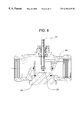
- FIG. 1 A cross-sectional schematic of a two-way balanced stem out closed external contoured plug valve 10 is shown in FIG. 1 .
- Contoured plug valve 10 has a valve body 12 .
- Removably secured in an aperture of valve body 12 is a bonnet 14 .
- Valve packing 16 exists on an exterior side of bonnet 14 , and is removably mounted in place via mounting nut 18 .
- Slidably mounted within packing 16 and through bonnet 14 is a valve stem 20 .
- Valve stem 20 slides in two directions generally along axis A, to operate the valve.
- Axis A may be angled with respect to the inlets and outlets for flow efficiency.
- An actuator (not shown) drives the valve stem 20 .
- Other embodiments may include elements such as knobs, wheels, etc. to drive valve stem 20 .
- a balanced plug 24 is attached to valve stem 20 . Note that the attachment of plug 24 to valve stem 20 may include some play to allow the plug 24 to self-align.
- Balanced plug 24 is generally cylindrical in shape, but can be of other closed perimeter shapes.
- Valve stem 20 is mounted to plug 24 at a center hub 26 .
- Supporting center hub 26 are multiple spokes 28 extending to a perimeter wall 30 of plug 24 .
- Plug 24 is prevented from moving in directions other than generally along axis A by a guide 32 extending from valve body 12 .
- the guide 32 may be integral with valve body 12 .
- the edges 34 , 36 of plug 24 are chamfered to allow plug 24 to tightly close against seals without damaging the seals. This feature is described in more detail below.
- a sliding seal o-ring 38 is positioned within a groove 40 of guide 32 , sealing plug 24 at perimeter wall 30 to block fluid passage between the exterior of the perimeter wall 30 of plug 24 and guide 32 .
- a close-off o-ring seal 42 is positioned within a groove 44 of bonnet 14 to block fluid passage between the exterior of the perimeter wall 30 of plug 24 and bonnet 14 when plug 24 is in a closed position.
- ridge 48 having an internal contoured wall 50 .
- Ridge 48 has a similar perimeter shape as that of plug 24 , but is sized slightly larger such that perimeter wall 30 of plug 24 may fit snugly within an interior of ridge 48 .
- Contour 50 of ridge 48 begins proximal to bonnet groove 44 and close-off o-ring seal 42 , and curves outward in a direction away from valve stem 20 .
- Contour 50 has a radius of curvature that may vary at different locations along contour 50 .
- contour 50 may have a constant radius of curvature.
- contour 50 may have a relatively large radius of curvature at a location proximal to bonnet groove 44 which gradually decreases until contour 50 ends at a location along a rim 54 of ridge 48 (see FIGS. 4 & 5 ).
- contour 50 may have a relatively small radius of curvature at a location proximal to bonnet groove 44 which gradually increases until contour 50 ends at a location along rim 54 of ridge 48 (see FIGS. 2 & 3 ).
- the gradual increase and/or decrease of the curvature profile of contour 50 may be determined by formula, or may be determined empirically.
- the curvature profile may be defined such that the radius of curvature fluctuates up and down along various locations of a single contoured wall 50 .
- the overall length of contour 50 and the depth of ridge 48 may vary from a relatively smaller ridge 48 and shorter contour 50 to a relatively larger ridge 48 and longer contour 50 .
- valve body and parts can be made from any of the conventional valve materials, including but not limited to cast iron, brass, stainless steel, other metallic materials, polymers, or composites.
- contoured plug valve 10 allow the valve to be constructed relatively compact in size.
- the actual contoured wall 50 itself can be manufactured using a lathe process or screw machines rather than being machined or cast like tapered V-gaps require. This ease of manufacture makes for a more economical cost efficient manufacturing process, and therefore a less expensive balanced plug valve relative to the aforementioned circular seat balanced plug valve devices.
- contoured wall 50 of the bonnet 14 characterizes the flow of a fluid through valve 10 .
- the fluid enters the valve, flows through a first port 56 , passes through plug 24 (while in an open position), and exits the valve through a second port 58 .
- the fluid passes inbetween the chamfered edge 34 of plug 24 , and contoured wall 50 .
- the positioning of chamfered edge 34 relative to contour 50 forms a gap 60 through which the fluid must flow.
- gap 60 becomes narrower and the flow is modulated to a lower rate.
- valve 10 is closed and there is a tight shutoff of the fluid flow.
- the flow rate can likewise be modulated upwards by moving plug 24 toward a fully open position. As plug 24 is lifted off of the close-off seal 42 , the flow rate increases at a rate at least partially dependent upon the shape of contour 50 . As plug 24 continues toward a fully open position, the flow rate will increase until valve 10 is fully open. The flow rate can be modulated at all points along the valve stroke between the fully opened and fully closed positions through adjustments of the position of plug 24 .
- the dimensions of the gap 60 change. These variations significantly affect the sensitivity and overall ability in controlling the modulation of the flow rate.
- contour 50 has a relatively large radius of curvature at a location on contour 50 proximal to groove 44 in bonnet 14 which gradually decreases as contour 50 extends toward rim 54 (see FIG. 5 ).
- plug 24 and valve stem 20 must travel a relatively large distance at the bonnet 14 end of contour 50 to affect the width dimension of gap 60 .
- a relatively significant portion of the valve stroke may be traveled while the flow rate of the fluid is marginally affected.
- contour 50 has a relatively small radius of curvature at a location on contour 50 proximal to groove 44 in bonnet 14 which gradually increases as contour 50 extends toward rim 54 (see FIG. 3 ).
- plug 24 and valve stem 20 need only travel a relatively small distance at the bonnet 14 end of contour 50 to affect the width dimension of gap 60 .
- valve stem 20 need only be moved a small distance to achieve a desired change in the flow rate.
- valve stroke From approximately 26% valve stroke to 100% valve stroke, the gap provided between the contoured wall and the plug was large enough that the contour had little affect on the flow rate. Between approximately 26% and 68% of valve stroke, the flow coefficient increased from approximately 2.6 to 22. This is a slope of approximately 0.46. The increase in the flow coefficient began to diminish beyond 68% of valve stroke due to other limiting factors such as friction coefficients, shape and size of the ports, and other generally known flow factors not discussed here.
- FIGS. 2-10 are various embodiments in which a contoured wall 50 is useful for the control and modulation of flow rates.
- FIGS. 2-5 are the same valve structure as that of FIG. 1, but with different variations of the shape of the contoured wall 50 . It should be noted that these figures are only representative samples of a few of the multitude of possible contoured wall 50 shapes.
- a contour shape can have any combination of an infinite number of radii of curvature along a single perimeter edge, which results in the inability to depict herein all possible contoured wall shapes.
- FIGS. 6 and 8 are external plug configurations.
- an interior portion of bonnet 62 is sized to fit within perimeter wall 64 of plug 66 .
- Plug 66 is chamfered on its internal edge 68 such that it fits snugly around contoured wall 70 .
- contoured wall 70 can be varied in its shape and size to achieve desired flow characteristics relative to valve stroke.
- valve stem 21 is configured such that plug 24 is mounted closer to the internal valve stem end 22 than in valve 10 of FIG. 1 .
- valve stem 21 does not slide through bonnets 15 and 63 .
- FIG. 9 is a 3- way balanced mixing valve 72 .
- the contoured walls 50 and 51 are similar to those of the valve 10 of FIG. 1, however, there are two contoured walls 50 and 51 due to the additional port 74 .
- the valve 76 of FIG. 10 is mechanically identical to FIG. 9, but the flow direction is reversed, making valve 76 a diverting valve.
Abstract
Description
Claims (26)
Priority Applications (1)
| Application Number | Priority Date | Filing Date | Title |
|---|---|---|---|
| US09/314,257 US6394135B2 (en) | 1999-05-18 | 1999-05-18 | Balanced plug valve with contour wall |
Applications Claiming Priority (1)
| Application Number | Priority Date | Filing Date | Title |
|---|---|---|---|
| US09/314,257 US6394135B2 (en) | 1999-05-18 | 1999-05-18 | Balanced plug valve with contour wall |
Publications (2)
| Publication Number | Publication Date |
|---|---|
| US20010001964A1 US20010001964A1 (en) | 2001-05-31 |
| US6394135B2 true US6394135B2 (en) | 2002-05-28 |
Family
ID=23219229
Family Applications (1)
| Application Number | Title | Priority Date | Filing Date |
|---|---|---|---|
| US09/314,257 Expired - Lifetime US6394135B2 (en) | 1999-05-18 | 1999-05-18 | Balanced plug valve with contour wall |
Country Status (1)
| Country | Link |
|---|---|
| US (1) | US6394135B2 (en) |
Cited By (13)
| Publication number | Priority date | Publication date | Assignee | Title |
|---|---|---|---|---|
| US20050000577A1 (en) * | 2003-07-03 | 2005-01-06 | Alman Paul T. | Multiple material valve plug for high temperature operation |
| US20050098220A1 (en) * | 2003-11-06 | 2005-05-12 | Invensys Building Systems, Inc. | Balanced globe valve |
| US20070144595A1 (en) * | 2005-12-28 | 2007-06-28 | Dan Geva | Hollow piston valve |
| US20080042095A1 (en) * | 2006-08-17 | 2008-02-21 | Jabcon Jr Leonard J | Valve assembly |
| US20080053545A1 (en) * | 2006-09-05 | 2008-03-06 | Wears William E | Parabolic bonnet for three-way valve |
| US20090057595A1 (en) * | 2005-03-17 | 2009-03-05 | Fisher Controls International Llc | Fluid Pressure Control Device Having a Throttling Element Seal |
| US20150362070A1 (en) * | 2013-01-28 | 2015-12-17 | Emerson Process Management Regulator Technologies, Inc. | Piston Device and Pressure Regulator Using Same |
| WO2016044434A1 (en) * | 2014-09-17 | 2016-03-24 | Schneider Electric Buildings, Llc | Balanced globe valve assembly |
| US9341270B2 (en) | 2014-07-28 | 2016-05-17 | Schneider Electric Buildings, Llc | Tool-less valve actuator connector for a globe valve assembly |
| US9541212B2 (en) | 2014-08-19 | 2017-01-10 | Schneider Electric Buildings, Llc | Tool-less valve stem connector assembly for a globe valve assembly |
| US20170082204A1 (en) * | 2015-09-18 | 2017-03-23 | Hamilton Sundstrand Corporation | Metering devices |
| US20170152964A1 (en) * | 2014-06-13 | 2017-06-01 | Rsg Electronic Gmbh | Valve device for controlling media flows of any type |
| US10690263B2 (en) * | 2015-05-06 | 2020-06-23 | Fisher Controls International Llc | Valve trim apparatus having multiple fluid flow control members |
Families Citing this family (3)
| Publication number | Priority date | Publication date | Assignee | Title |
|---|---|---|---|---|
| DE202007017803U1 (en) * | 2007-12-20 | 2009-04-23 | Hengst Gmbh & Co.Kg | Valve assembly with curved sealing surface |
| JP5366623B2 (en) * | 2009-04-09 | 2013-12-11 | 株式会社ミヤワキ | Double seat balance valve |
| CN104100418B (en) * | 2014-07-08 | 2016-03-23 | 无锡隆盛科技股份有限公司 | A kind of pressure relief of electric EGR valve |
Citations (12)
| Publication number | Priority date | Publication date | Assignee | Title |
|---|---|---|---|---|
| US1208590A (en) * | 1915-08-28 | 1916-12-12 | William J Lilly | Valve. |
| US1277153A (en) * | 1916-12-27 | 1918-08-27 | Alexander J Mcdonough | Valve. |
| US2141614A (en) * | 1935-07-06 | 1938-12-27 | Yarnall Waring Co | Oven valve and the like |
| US2921603A (en) * | 1957-02-12 | 1960-01-19 | Chaplin Fulton Mfg Company | Double ported poppet valve |
| US3857542A (en) * | 1972-06-06 | 1974-12-31 | Westinghouse Electric Corp | Noise suppressing throttle valve |
| GB2067722A (en) * | 1980-01-23 | 1981-07-30 | Northern Eng Ind | Steam turbine governing valve |
| US4360370A (en) * | 1979-10-24 | 1982-11-23 | General Electric Co. | Poppet valve for baghouse outlet plenum |
| US4375821A (en) * | 1980-01-25 | 1983-03-08 | Kubota, Ltd. | Control value |
| US4429716A (en) * | 1982-02-01 | 1984-02-07 | Conrad Richard A | Control valve |
| US4444222A (en) * | 1981-05-18 | 1984-04-24 | Hi-Sonic Co., Ltd. | Automatic liquid-supply stopper plug |
| US4892118A (en) * | 1980-09-30 | 1990-01-09 | General Electric Company | Silent valve |
| US5318270A (en) * | 1991-11-19 | 1994-06-07 | Gec Alsthom Sa | Valve with a crenellated seat |
-
1999
- 1999-05-18 US US09/314,257 patent/US6394135B2/en not_active Expired - Lifetime
Patent Citations (12)
| Publication number | Priority date | Publication date | Assignee | Title |
|---|---|---|---|---|
| US1208590A (en) * | 1915-08-28 | 1916-12-12 | William J Lilly | Valve. |
| US1277153A (en) * | 1916-12-27 | 1918-08-27 | Alexander J Mcdonough | Valve. |
| US2141614A (en) * | 1935-07-06 | 1938-12-27 | Yarnall Waring Co | Oven valve and the like |
| US2921603A (en) * | 1957-02-12 | 1960-01-19 | Chaplin Fulton Mfg Company | Double ported poppet valve |
| US3857542A (en) * | 1972-06-06 | 1974-12-31 | Westinghouse Electric Corp | Noise suppressing throttle valve |
| US4360370A (en) * | 1979-10-24 | 1982-11-23 | General Electric Co. | Poppet valve for baghouse outlet plenum |
| GB2067722A (en) * | 1980-01-23 | 1981-07-30 | Northern Eng Ind | Steam turbine governing valve |
| US4375821A (en) * | 1980-01-25 | 1983-03-08 | Kubota, Ltd. | Control value |
| US4892118A (en) * | 1980-09-30 | 1990-01-09 | General Electric Company | Silent valve |
| US4444222A (en) * | 1981-05-18 | 1984-04-24 | Hi-Sonic Co., Ltd. | Automatic liquid-supply stopper plug |
| US4429716A (en) * | 1982-02-01 | 1984-02-07 | Conrad Richard A | Control valve |
| US5318270A (en) * | 1991-11-19 | 1994-06-07 | Gec Alsthom Sa | Valve with a crenellated seat |
Cited By (33)
| Publication number | Priority date | Publication date | Assignee | Title |
|---|---|---|---|---|
| US6997211B2 (en) * | 2003-07-03 | 2006-02-14 | Fisher Controls International Llc. | Multiple material valve plug for high temperature operation |
| US20050000577A1 (en) * | 2003-07-03 | 2005-01-06 | Alman Paul T. | Multiple material valve plug for high temperature operation |
| AU2004288920B2 (en) * | 2003-11-06 | 2008-04-17 | Tac, Llc | Balanced globe valve |
| US20050098220A1 (en) * | 2003-11-06 | 2005-05-12 | Invensys Building Systems, Inc. | Balanced globe valve |
| WO2005047742A1 (en) | 2003-11-06 | 2005-05-26 | Invensys Building Systems, Inc. | Balanced globe valve |
| US20060048827A1 (en) * | 2003-11-06 | 2006-03-09 | Invensys Building Systems, Inc. | Balanced globe valve |
| US7017608B2 (en) | 2003-11-06 | 2006-03-28 | Invensys Building Systems, Inc. | Balanced globe valve |
| US7159617B2 (en) | 2003-11-06 | 2007-01-09 | Invensys Building Systems, Inc. | Balanced globe valve |
| CN100436897C (en) * | 2003-11-06 | 2008-11-26 | Tac有限责任公司 | Balanced globe valve |
| US20090057595A1 (en) * | 2005-03-17 | 2009-03-05 | Fisher Controls International Llc | Fluid Pressure Control Device Having a Throttling Element Seal |
| US9046184B2 (en) * | 2005-03-17 | 2015-06-02 | Fisher Controls International Llc | Fluid pressure control device having a throttling element seal |
| US20130221259A1 (en) * | 2005-03-17 | 2013-08-29 | Fisher Controls International Llc | Fluid pressure control device having a throttling element seal |
| US8403003B2 (en) * | 2005-03-17 | 2013-03-26 | Fisher Controls International Llc | Fluid pressure control device having a throttling element seal |
| US20070144595A1 (en) * | 2005-12-28 | 2007-06-28 | Dan Geva | Hollow piston valve |
| US20080042095A1 (en) * | 2006-08-17 | 2008-02-21 | Jabcon Jr Leonard J | Valve assembly |
| US7849876B2 (en) * | 2006-08-17 | 2010-12-14 | Parker-Hannifin Corporation | Valve assembly with sealing force |
| US8297316B2 (en) | 2006-09-05 | 2012-10-30 | Fisher Controls International Llc | Parabolic bonnet for three-way valve |
| US7832426B2 (en) * | 2006-09-05 | 2010-11-16 | Fisher Controls International Llc | Parabolic bonnet for three-way valve |
| AU2007292535B2 (en) * | 2006-09-05 | 2013-09-05 | Fisher Controls International Llc | Bonnet for three-way valve |
| US20080053545A1 (en) * | 2006-09-05 | 2008-03-06 | Wears William E | Parabolic bonnet for three-way valve |
| US20110042601A1 (en) * | 2006-09-05 | 2011-02-24 | Fisher Controls International Llc | Parabolic Bonnet For Three-Way Valve |
| US20150362070A1 (en) * | 2013-01-28 | 2015-12-17 | Emerson Process Management Regulator Technologies, Inc. | Piston Device and Pressure Regulator Using Same |
| US9920835B2 (en) * | 2013-01-28 | 2018-03-20 | Emerson Process Management Regulator Technologies, Inc. | Piston device and pressure regulator using same |
| US20170152964A1 (en) * | 2014-06-13 | 2017-06-01 | Rsg Electronic Gmbh | Valve device for controlling media flows of any type |
| US11168808B2 (en) * | 2014-06-13 | 2021-11-09 | Rsg Electronic Gmbh | Valve device for controlling media flows of any type |
| US9341270B2 (en) | 2014-07-28 | 2016-05-17 | Schneider Electric Buildings, Llc | Tool-less valve actuator connector for a globe valve assembly |
| US9541212B2 (en) | 2014-08-19 | 2017-01-10 | Schneider Electric Buildings, Llc | Tool-less valve stem connector assembly for a globe valve assembly |
| US9371936B2 (en) | 2014-09-17 | 2016-06-21 | Schneider Electric Buildings, Llc | Balanced globe valve assembly |
| WO2016044434A1 (en) * | 2014-09-17 | 2016-03-24 | Schneider Electric Buildings, Llc | Balanced globe valve assembly |
| US10690263B2 (en) * | 2015-05-06 | 2020-06-23 | Fisher Controls International Llc | Valve trim apparatus having multiple fluid flow control members |
| US11236845B2 (en) | 2015-05-06 | 2022-02-01 | Fisher Controls International Llc | Valve trim apparatus having multiple fluid flow control members |
| US20170082204A1 (en) * | 2015-09-18 | 2017-03-23 | Hamilton Sundstrand Corporation | Metering devices |
| US10030779B2 (en) * | 2015-09-18 | 2018-07-24 | Hamilton Sundstrand Corporation | Metering devices |
Also Published As
| Publication number | Publication date |
|---|---|
| US20010001964A1 (en) | 2001-05-31 |
Similar Documents
| Publication | Publication Date | Title |
|---|---|---|
| US6394135B2 (en) | Balanced plug valve with contour wall | |
| US7159617B2 (en) | Balanced globe valve | |
| EP0188130B1 (en) | Valve | |
| CA2031609C (en) | Valve | |
| JP4181222B2 (en) | Automatic adjustment valve device | |
| EP0043188B1 (en) | Method of attenuating fluid flow passing through a valve and a valve therefor | |
| US5273075A (en) | Diverter valve | |
| US7073532B2 (en) | Valve assembly | |
| US7104281B2 (en) | Fluid flow regulation | |
| US11236845B2 (en) | Valve trim apparatus having multiple fluid flow control members | |
| US5156188A (en) | Flow control valve | |
| US5116019A (en) | Control valve | |
| US8556226B2 (en) | Valve with the device enhancing capability of its closure member and related seat ring to resist erosion | |
| JP3728546B2 (en) | Variable constant flow valve device | |
| US5603356A (en) | Fluid flow control valves | |
| JP3851378B2 (en) | Automatic adjustment valve device | |
| JP3111274B2 (en) | Automatic constant pressure valve device | |
| US20040129908A1 (en) | Valve assembly | |
| US3396742A (en) | Flat-sided stream flow valve | |
| JPH09126349A (en) | Variable constant flow valve device | |
| GB2144817A (en) | Pipe coupling-diverter valves |
Legal Events
| Date | Code | Title | Description |
|---|---|---|---|
| AS | Assignment |
Owner name: BARBER-COLMAN, ILLINOIS Free format text: ASSIGNMENT OF ASSIGNORS INTEREST;ASSIGNORS:ERICKSON, IRVING C.;BURWELL, GARY B.;DICKINSON, BONNIE J.;AND OTHERS;REEL/FRAME:009978/0774 Effective date: 19990506 |
|
| STCF | Information on status: patent grant |
Free format text: PATENTED CASE |
|
| AS | Assignment |
Owner name: INVENSYS BUILDING SYSTEMS, INC., ILLINOIS Free format text: CHANGE OF NAME;ASSIGNOR:BARBER-COLMAN COMPANY;REEL/FRAME:015156/0913 Effective date: 19991214 |
|
| AS | Assignment |
Owner name: DEUTSCHE BANK, AG LOND, UNITED KINGDOM Free format text: SECURITY AGREEMENT;ASSIGNOR:INVENSYS BUILDING SYSTEMS, INC.;REEL/FRAME:015190/0297 Effective date: 20040401 |
|
| FPAY | Fee payment |
Year of fee payment: 4 |
|
| AS | Assignment |
Owner name: INVENSYS BUILDING SYSTEMS, INC., ILLINOIS Free format text: RELEASE AND TERMINATION OF SECURITY INTEREST;ASSIGNOR:DEUTSCHE BANK AG, LONDON BRANCH;REEL/FRAME:018087/0282 Effective date: 20060713 |
|
| FEPP | Fee payment procedure |
Free format text: PAYOR NUMBER ASSIGNED (ORIGINAL EVENT CODE: ASPN); ENTITY STATUS OF PATENT OWNER: LARGE ENTITY |
|
| AS | Assignment |
Owner name: TAC, LLC, ILLINOIS Free format text: MERGER;ASSIGNOR:INVENSYS BUILDING SYSTEMS INC.;REEL/FRAME:020645/0870 Effective date: 20061214 |
|
| FPAY | Fee payment |
Year of fee payment: 8 |
|
| FPAY | Fee payment |
Year of fee payment: 12 |