JP2014172134A - Processing device - Google Patents
Processing device Download PDFInfo
- Publication number
- JP2014172134A JP2014172134A JP2013048622A JP2013048622A JP2014172134A JP 2014172134 A JP2014172134 A JP 2014172134A JP 2013048622 A JP2013048622 A JP 2013048622A JP 2013048622 A JP2013048622 A JP 2013048622A JP 2014172134 A JP2014172134 A JP 2014172134A
- Authority
- JP
- Japan
- Prior art keywords
- gear
- face plate
- torque
- power transmission
- planetary
- Prior art date
- Legal status (The legal status is an assumption and is not a legal conclusion. Google has not performed a legal analysis and makes no representation as to the accuracy of the status listed.)
- Pending
Links
Images


Classifications
-
- B—PERFORMING OPERATIONS; TRANSPORTING
- B23—MACHINE TOOLS; METAL-WORKING NOT OTHERWISE PROVIDED FOR
- B23B—TURNING; BORING
- B23B5/00—Turning-machines or devices specially adapted for particular work; Accessories specially adapted therefor
- B23B5/16—Turning-machines or devices specially adapted for particular work; Accessories specially adapted therefor for bevelling, chamfering, or deburring the ends of bars or tubes
- B23B5/161—Devices attached to the workpiece
- B23B5/163—Devices attached to the workpiece with an external clamping device
-
- B—PERFORMING OPERATIONS; TRANSPORTING
- B23—MACHINE TOOLS; METAL-WORKING NOT OTHERWISE PROVIDED FOR
- B23B—TURNING; BORING
- B23B3/00—General-purpose turning-machines or devices, e.g. centre lathes with feed rod and lead screw; Sets of turning-machines
- B23B3/22—Turning-machines or devices with rotary tool heads
- B23B3/26—Turning-machines or devices with rotary tool heads the tools of which perform a radial movement; Rotary tool heads thereof
-
- Y—GENERAL TAGGING OF NEW TECHNOLOGICAL DEVELOPMENTS; GENERAL TAGGING OF CROSS-SECTIONAL TECHNOLOGIES SPANNING OVER SEVERAL SECTIONS OF THE IPC; TECHNICAL SUBJECTS COVERED BY FORMER USPC CROSS-REFERENCE ART COLLECTIONS [XRACs] AND DIGESTS
- Y10—TECHNICAL SUBJECTS COVERED BY FORMER USPC
- Y10T—TECHNICAL SUBJECTS COVERED BY FORMER US CLASSIFICATION
- Y10T82/00—Turning
- Y10T82/22—Portable lathe for pipe turning
Abstract
Description
本発明は、被加工物、具体的には、配管(パイプ)を加工するための装置に関する。 The present invention relates to an apparatus for processing a workpiece, specifically, piping (pipe).
配管の加工装置(以下、単に、「加工装置」ということがある。)には、例えば、特許文献1,2に示されているようなものがある。 Examples of piping processing apparatuses (hereinafter, simply referred to as “processing apparatuses”) include those disclosed in Patent Documents 1 and 2.
ここで、特許文献1,2の加工装置の構成及び動作について説明する。これらの加工装置は、環状のハウジングと面板、工具ホルダ、ギアボックス、及び1つの駆動装置(モータ)から構成されている。これらの加工装置は、ハウジングに対称的に設けられた複数のクランプが配管を挟持することによって基本的には配管の外側に固定される。面板はハウジングに対して回転可能に支持されており、面板の、ハウジングと反対側の表面上には、工具を具える工具ホルダが装着されている。なお、特許文献1,2では、工具はバイトであり、バイトとは、配管の開先加工、切断等に用いる刃物である。 Here, the configuration and operation of the processing apparatus disclosed in Patent Documents 1 and 2 will be described. These processing apparatuses are composed of an annular housing, a face plate, a tool holder, a gear box, and one drive device (motor). These processing apparatuses are basically fixed to the outside of the pipe by sandwiching the pipe with a plurality of clamps provided symmetrically on the housing. The face plate is rotatably supported with respect to the housing, and a tool holder including a tool is mounted on the surface of the face plate opposite to the housing. In Patent Documents 1 and 2, the tool is a cutting tool, and the cutting tool is a blade used for pipe groove processing, cutting, and the like.
これらの加工装置の面板は、外歯車である面板ギアを有し、面板ギアに対して相対的に回転可能であるが、通常は、面板ギアと摩擦によって同方向に等速で従動するリングギアを具える。リングギアは外歯車である外周側ギアと、内歯車である内周側ギアを有しており、内周側ギアは、動力伝達軸上に設けられる動力伝達入力ギアと噛み合っている。動力伝達軸は、面板内部に回転可能に軸支されており、面板の表面に露出している動力伝達出力ギアを具えている。動力伝達出力ギアは、工具ホルダが具える工具送りギアと噛み合い、工具送りギアが回転することによって、ねじ送り機構等を介して、工具が配管に近づく、又は離れる方向に移動する。 The face plate of these processing devices has a face plate gear which is an external gear, and is rotatable relative to the face plate gear, but is usually a ring gear driven at a constant speed in the same direction by friction with the face plate gear. With The ring gear has an outer peripheral side gear that is an external gear and an inner peripheral side gear that is an internal gear, and the inner peripheral side gear meshes with a power transmission input gear provided on a power transmission shaft. The power transmission shaft is rotatably supported inside the face plate and includes a power transmission output gear exposed on the surface of the face plate. The power transmission output gear meshes with the tool feed gear included in the tool holder, and the tool feed gear rotates, so that the tool moves toward or away from the pipe via a screw feed mechanism or the like.
次に、モータから各種ギアへどのようにトルクが伝達されるのかを説明する。ギアボックス内には、モータから面板ギアへトルクを伝達するための第一ギア機構と、リングギアの外周側ギアにトルクを伝達するための第二ギア機構が設けられている。第一ギア機構及び面板ギアの組合せと、第二ギア機構及びリングギアの組合せとでは、変速比が異なるように設定されている。モータから面板ギアへは、第一ギア機構を通じて常にトルクが伝達されるが、第二ギア機構を通じてリングギアにトルクを伝達する為には、ギアボックスに具えられたレバーによる切換え作業が必要になる。 Next, how torque is transmitted from the motor to various gears will be described. A first gear mechanism for transmitting torque from the motor to the face plate gear and a second gear mechanism for transmitting torque to the outer peripheral gear of the ring gear are provided in the gear box. The gear ratio is set to be different between the combination of the first gear mechanism and the face plate gear and the combination of the second gear mechanism and the ring gear. Torque is always transmitted from the motor to the face plate gear through the first gear mechanism, but in order to transmit torque to the ring gear through the second gear mechanism, a switching operation using a lever provided in the gear box is required. .
ここで、第一ギア機構のみが駆動されている場合は、モータからのトルクは面板ギアのみに伝達されるが、面板ギアとの摩擦によってリングギアも同方向に等速で従動しているため、動力伝達軸は回転しない。従って、面板ギアの回転に伴い、面板及びこれに装着された工具ホルダは配管の周方向を旋回する。一方、レバーを切換え、第二ギア機構を駆動した場合、モータから第二ギア機構を通じてリングギアにトルクが伝達され、上記のとおり、第一ギア機構及び面板ギアの組合せと、第二ギア機構及びリングギアの組合せとでは、変速比が異なるため、面板ギアとリングギアとの間に回転数の差が生じる。かくして、リングギアの内周側ギアが動力伝達入力ギアを通じて、動力伝達軸を回転させるため、工具を配管に対して近づけ、又は遠ざけることができる。 Here, when only the first gear mechanism is driven, the torque from the motor is transmitted only to the face plate gear, but the ring gear is also driven at the same speed in the same direction by friction with the face plate gear. The power transmission shaft does not rotate. Therefore, with the rotation of the face plate gear, the face plate and the tool holder attached thereto rotate in the circumferential direction of the pipe. On the other hand, when the lever is switched and the second gear mechanism is driven, torque is transmitted from the motor to the ring gear through the second gear mechanism, and as described above, the combination of the first gear mechanism and the face plate gear, the second gear mechanism and Since the gear ratio is different in the ring gear combination, a difference in rotational speed occurs between the face plate gear and the ring gear. Thus, since the inner peripheral gear of the ring gear rotates the power transmission shaft through the power transmission input gear, the tool can be moved closer to or away from the pipe.
しかしながら、特許文献1,2に示されているような従来の加工装置では、工具の移動・停止をコントロールするために行う作業、すなわち、リングギアにトルクを伝えるための第二ギア機構を駆動するか否かの切換え作業を人がレバーで直接行わなければならないという不便さがある。 However, in the conventional machining apparatus as shown in Patent Documents 1 and 2, the work to be performed to control the movement and stop of the tool, that is, the second gear mechanism for transmitting torque to the ring gear is driven. There is an inconvenience that a person must perform the switching operation of whether or not directly with a lever.
また、工具の移動速度に影響する動力伝達軸の回転数は、上記の構成から明らかなように、面板ギアとリングギアとの回転数の差に依存するため、面板ギアとリングギアの歯数を異なるものにする、リングギアの外周側ギアとして、径の異なる2種以上のギアを設ける、又はギアボックス内の第二ギア機構として、変速比の異なる2種以上のギア機構を設ける等して、面板ギアとリングギアとの回転数の差のバリエーションをいくつか作り出すことができるが、スペース的、コスト的な観点から、これには限界があり、また、予め設定したバリエーションに基づく回転数の差しか実現することができないという問題もある。 In addition, as apparent from the above configuration, the rotational speed of the power transmission shaft that affects the moving speed of the tool depends on the rotational speed difference between the face plate gear and the ring gear, so the number of teeth of the face plate gear and the ring gear. Different gears, providing two or more gears with different diameters as the outer peripheral gear of the ring gear, or providing two or more gear mechanisms with different gear ratios as the second gear mechanism in the gear box, etc. Although it is possible to create several variations of the difference in rotational speed between the face plate gear and the ring gear, this is limited from the viewpoint of space and cost, and the rotational speed based on a preset variation. There is also a problem that only this can be realized.
また、工具の移動距離は、人が、工具の移動速度を考慮しながらレバーを直接操作してコントロールしなければならないから、例えば、配管に開先加工を施す際、特に、工具の送り量(工具が配管に近づく方向の移動距離。)を目視で正確にコントロールしなければならず、精密な加工を施すのが難しい。 In addition, since the movement distance of the tool must be controlled by manipulating the lever directly while taking the movement speed of the tool into account, for example, when performing groove processing on a pipe, the tool feed amount ( The distance that the tool moves closer to the pipe must be accurately controlled visually, making it difficult to perform precise machining.
なお、エアーシリンダ等を利用してレバーを遠隔操作することも可能ではあるが、結局は機械的な構成によりレバー操作をしているに過ぎないため応答性が低く、工具の移動・停止、移動速度、移動距離のコントロールの正確性に欠ける。 Although it is possible to remotely control the lever using an air cylinder, etc., the responsiveness is low because it is merely a lever operation due to the mechanical configuration, and the tool is moved / stopped / moved. Inaccurate control of speed and distance traveled.
そこで、本発明は、前述した従来技術の問題点に鑑み、工具の移動・停止、移動速度、移動距離をレバー操作に依らずに、自在にコントロールできる加工装置を提供することをその目的とする。 In view of the above-described problems of the prior art, an object of the present invention is to provide a machining apparatus that can freely control the movement / stop of the tool, the movement speed, and the movement distance without depending on the lever operation. .
本発明は、ハウジングと、
前記ハウジングに対して回転可能に設けられる、面板ギアを有する面板及び外周側ギアと内周側ギアを有するリングギアと、
前記面板に回転可能に軸支され、前記リングギアからトルクが伝達される動力伝達入力ギアと該動力伝達入力ギアからのトルクを伝達するための動力伝達出力ギアを具える動力伝達軸と、
前記動力伝達出力ギアからのトルクが直線運動に変換されて進退動する工具を保持する、前記面板に取付けられる工具ホルダと、
前記ハウジングに取付けられ、第一駆動装置及び第二駆動装置と連結される、前記面板ギア及びリングギアにトルクを伝達する差動装置を有し、
前記差動装置は、
前記第一駆動装置からトルクが伝達される第一ギアと
前記第一ギアと同軸線上に設けられる第二ギアと、
前記第二駆動装置からのトルクが伝達されるプラネタリキャリアに具えられる、前記第一ギア及び第二ギアと噛合い、前記第一ギア及び第二ギアの軸を中心に公転するプラネタリギアとを具え、
前記第一ギア又は第二ギアからのトルクがそれぞれ前記面板ギア又はリングギアを回転させることを特徴とする加工装置によって前記課題を解決した。
The present invention includes a housing;
A face plate having a face plate gear and a ring gear having an outer peripheral side gear and an inner peripheral side gear provided rotatably with respect to the housing;
A power transmission shaft that is rotatably supported by the face plate and includes a power transmission input gear that transmits torque from the ring gear, and a power transmission output gear that transmits torque from the power transmission input gear;
A tool holder attached to the face plate for holding a tool that moves forward and backward by converting torque from the power transmission output gear into linear motion;
A differential device attached to the housing and connected to the first drive device and the second drive device for transmitting torque to the face plate gear and the ring gear;
The differential is
A first gear to which torque is transmitted from the first driving device; a second gear provided on the same line as the first gear;
A planetary carrier provided with a planetary carrier to which torque from the second driving device is transmitted, and a planetary gear that meshes with the first gear and the second gear and revolves around an axis of the first gear and the second gear ,
The above problems have been solved by a machining apparatus in which the torque from the first gear or the second gear rotates the face plate gear or the ring gear, respectively.
本発明によれば、差動装置と連結される第一駆動装置及び第二駆動装置を操作し、それらの回転数、回転方向をコントロールするだけで、工具の移動・停止、移動速度、移動距離を自在にコントロールすることができるから、従来のレバー操作は不要である。 According to the present invention, the tool is moved / stopped, the moving speed, the moving distance only by operating the first driving device and the second driving device connected to the differential device and controlling the number of rotations and the rotation direction thereof. Can be controlled freely, so conventional lever operation is unnecessary.
また、プラネタリキャリアが固定、第一ギアが回転の場合、面板ギアとリングギアが等速で回転するように各ギア比を構成すれば、第一ギアにトルクを伝達する第一駆動装置を駆動するだけで、面板ギアとリングギアの等速駆動を実現できるので好適である。 In addition, when the planetary carrier is fixed and the first gear is rotating, if the gear ratio is configured so that the face plate gear and the ring gear rotate at a constant speed, the first driving device that transmits torque to the first gear is driven. This is preferable because constant speed driving of the face plate gear and the ring gear can be realized.
また、プラネタリギアが第一ギア及び第二ギアとそれらの軸方向がそれぞれ直交するように噛合っている構成とすれば、差動装置の第一ギアと第二ギアの径方向のコンパクト化を図ることができ、プラネタリギアが第一ギア及び第二ギアとそれらの軸方向がそれぞれ平行になるように噛合っている構成とすれば、差動装置の第一ギア及び第二ギアの軸方向のコンパクト化を図ることができる。 Moreover, if the planetary gear is configured to mesh with the first gear and the second gear so that their axial directions are orthogonal to each other, the radial direction of the first gear and the second gear of the differential device can be made compact. If the planetary gear is configured to mesh with the first gear and the second gear so that their axial directions are parallel to each other, the axial direction of the first gear and the second gear of the differential gear Can be made compact.
本発明の実施例を図1〜7を参照して説明する。但し、本発明はこの実施形態に限定されるものではない。 An embodiment of the present invention will be described with reference to FIGS. However, the present invention is not limited to this embodiment.
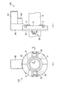
図1(a),(b)に示されるように、本発明の加工装置100は、ハウジング10、ハウジング10に回転可能に設けられる面板20、面板20に取付けられる工具ホルダ30、ハウジング10に取付けられている差動装置60、第一駆動装置であるモータM1、及び第二駆動装置であるモータM2を具える。モータM1,M2のモータ容量は特に限定されないが、後述するプラネタリキャリアを回転させるためには、比較的大きなトルクを要しないため、モータM2はモータM1に比べて小さいモータ容量のものでよい。
As shown in FIGS. 1A and 1B, a
ハウジング10は、図示されているように、環状であり、ハウジング10に設けられるクランプCが配管(パイプ)Pを挟持することによって、基本的には、配管Pの外側に固定される。この状態で、モータM1(又は、場合によっては、モータM2も含む。)のトルクによって面板20が回転し、工具ホルダ30に取付けられる工具(バイト)38が配管Pに押し付けられ、工具38が配管Pを削り、切断する。図2(a),(b)に示す加工装置100aは、加工装置100と同様の構成のもので、加工装置100の工具ホルダ30を、開先加工用の工具38aを有する工具ホルダ30aに変更したものである。加工装置100aによれば、加工装置100と同一の作動原理を用いて、配管Pの開先加工を行うことができる。このように、本発明の加工装置は、工具ホルダを変更するだけで、配管の切断・開先加工等のあらゆる加工に対応でき、場合によっては、溶接機としても対応できるものである。
As illustrated, the
次に、図3を用いて、本発明の加工装置の工具に係る動作について説明する。図3は、図1の加工装置100の3−3線横断面図である。ハウジング10には、ローラ12が設けられており、ローラ12は、面板20をハウジング10に対して回転可能に支持している。ローラ12は、通常、ハウジング10の周方向に複数個設けられている。面板20には、面板20と相対回転可能にリングギア40が嵌め込まれており、かくして、面板20とリングギア40はハウジング10に回転可能に設けられることになる。なお、図示は省略するが、面板20とリングギア40を別々に、ハウジング10に対して回転可能に設ける構成としてもよい。この構成によれば、面板20とリングギア40が相対回転したときの、面板20とリングギア40との摩擦が生じないため、その摩擦に起因する部品の摩耗を防止することができる。
Next, the operation | movement which concerns on the tool of the processing apparatus of this invention is demonstrated using FIG. 3 is a cross-sectional view taken along line 3-3 of the
面板20は、その外周側に面板ギア22を有し、リングギア40は、その外周側に外周側ギア42、内周側に内周側ギア44を有する。また、面板20は、動力伝達軸50を回転可能に軸支しており、動力伝達軸50に設けられる動力伝達入力ギア52は、内周側ギア44と噛合っている。なお、図3では、動力伝達軸50は、面板20の内周側に設けられているが、対称的に面板20の外周側に設けることもできる。面板ギア22と外周側ギア42には、後述するように、モータM1,M2からのトルクがそれぞれ別々のギアを通じて伝達される。動力伝達軸50は、面板20に軸支されているため、面板20及びリングギア40が同方向に等速で回転した場合、面板20及びリングギア40の回転軸を中心に回転する。このとき、動力伝達軸50は、自転(それ自体の軸を中心に回転)していない。一方、リングギア40の回転数が面板20の回転数よりも高い場合、動力伝達軸50は一方向へ自転し、リングギア40の回転数が面板20の回転数よりも低い場合、動力伝達軸50は他方向へ自転する。すなわち、動力伝達軸50は、面板20とリングギア40との間に回転数の差が生じたときにいずれかの方向へ自転する。
The
動力伝達軸50が自転すると、動力伝達出力ギア54を通じて、工具送りギア32にトルクが伝達され、ねじ送り機構等の直線運動変換機構34によってトルクが直線運動に変換され、工具保持具36及び工具38を矢印Aの方向に移動させる。すなわち、工具送りギア32の回転方向によって、工具38の移動方向が、工具送りギア32の回転数によって、工具38の移動速度が、そして、工具送りギア32の回転量によって、工具38の移動距離が決まる。なお、動力伝達軸50が自転していないとき、工具38は静止するのは言うまでもない。
When the
以上の説明から明らかなとおり、工具38の移動・停止、移動速度、移動距離等のコントロールは、動力伝達軸50、すなわち、面板20とリングギア40の回転をコントロールすることによって実現できる。
As is clear from the above description, the control of the movement / stop of the
ここで、図4を参照して、面板20とリングギア40の回転をコントロールするための、本発明の差動装置60について説明する。
Here, the
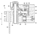
図4に示すように、本発明の第一実施形態の差動装置60は、軸71の軸線上に、第一ギア62,62a及び第二ギア64を具える。第一ギア62,62aは、軸71上に回転不能に設けられ、第二ギア64は、軸71上に回転可能に設けられている。第一ギア62と第二ギア64の間には、プラネタリギア68,68が第一ギア62及び第二ギア64と噛合うように設けられ、プラネタリギア68,68は、プラネタリキャリア66によって回転可能に軸支されている。図示しているように、プラネタリギア68の作動、及びトルク伝達をより安定させるために、プラネタリギア68を複数設けるのがよい。プラネタリキャリア66は、モータM2から第二入力中間ギア74、第二入力ギア76を通じてトルクが伝達され、第一ギア62及び第二ギア64の軸を中心に回転する。従って、プラネタリキャリア66が回転すると、プラネタリギア68,68が第一ギア62及び第二ギア64と噛合った状態で第一ギア62及び第二ギア64の軸を中心に公転する。第一出力ギア86には、モータM1から第一入力ギア72、第一ギア62aを通じてトルクが伝達され、また、第二出力ギア84には第二ギア64からのトルクが第二出力中間ギア82を通じて伝達される。第一出力ギア86、第二出力ギア84は、それぞれ、面板ギア22、外周側ギア42(図3参照。)と噛合い、かくして、面板ギア22及び外周側ギア42にトルクが伝達されることになる。なお、面板ギア22を回転させるためには比較的大きなトルクを要するため、モータM1からのトルクをダイレクトに伝達できる第二出力ギア86に面板ギア22を噛み合わせる構成とするのがよい。また、第一ギアは、図示している第一ギア62と62aのように、それらが同方向に等速で回転するようにされていれば、別個のギアとしてもよく、一方で、第二ギア64と、第二ギア64aのように隣り合っている場合は単一のギアとしてもよい。また、ある一定以上の負荷が掛かった場合に、モータからのトルクを遮断するためのトルクリミッタを適宜設けてもよい。
As shown in FIG. 4, the
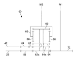
次に、図5を用いて、差動装置60の基本的な動作について説明する。図5は、差動装置60の要部を示したスケルトン図である。プラネタリキャリア66を回転しないように固定し、モータM1を駆動させた場合、モータM1からのトルクは第一入力ギア72を通じて第一ギア62aに伝達される。第一ギア62aと第一ギア62は同方向に回転するようにされているため、モータM1からのトルクは第一ギア62に伝達され、次いで、プラネタリギア68,68に伝達される。このとき、プラネタリキャリア66は回転しないように、サーボロック等のモータM2自体の機能又は機械的な手段で固定されているため、プラネタリギア68,68は公転せずに、その場で回転し、第二ギア64にトルクを伝達する。なお、プラネタリギア68,68と第一ギア62及び第二ギア64は、それらの軸方向がそれぞれ直交しているため、第一ギア62と第二ギア64は逆方向に回転する。第二ギア64に伝えられたトルクは、第二ギア64a及び第二中間出力ギア82を介して第二出力ギア84へ伝達される。一方、第一出力ギア86には、第一ギア62aからトルクが伝達される。このようにして、面板ギア22及び外周側ギア42に、第一出力ギア86及び第二出力ギア84から同方向のトルクがそれぞれ伝達されることになる。ここで、第一入力ギア72、第一ギア62a、第一出力ギア86、及び面板ギア22の変速比と、第一ギア62,62a、プラネタリギア68、第二ギア64,64a、第二中間出力ギア82、第二出力ギア84、及び外周側ギア42の変速比を等しいものにしておけば、上記のとおり、プラネタリキャリア66を固定し、モータM1を駆動するだけで、面板ギア22及び外周側ギア42を同方向に等速で回転させることができるため、面板ギア22及び外周側ギア42を同方向に等速で回転させるための駆動装置の制御が簡便に行える。なお、この場合、モータM1の回転数に応じて面板ギア22及び外周側ギア42の回転数を変えることができる。
Next, the basic operation of the
プラネタリキャリア66を固定し、モータM1を一定の速度で駆動している状態から、プラネタリキャリア66を第一ギア62の回転方向と逆方向に回転させると、第一ギア62の回転とは相対的にプラネタリギア68,68が公転するため、プラネタリギア68,68の回転数が上がる。これに伴い、第二ギア64の回転数も上がるため、かくして、面板ギア22よりも外周側ギア42の同方向の回転に係る回転数を上げることができる。一方、プラネタリキャリア66を固定し、モータM1を一定の速度で駆動している状態から、プラネタリキャリア66を第一ギア62の回転方向と同方向に回転させると、第一ギア62の回転と同方向にプラネタリギア68,68が公転するため、プラネタリギア68,68の回転数が下がる。これに伴い、第二ギア64の回転数も下がるため、かくして、面板ギア22よりも外周側ギア42の同方向の回転に係る回転数を下げることができる。なお、プラネタリキャリア66の回転数をさらに上げると、第二ギア64の回転を停止させ、又は逆転させることも出来る。便宜上、モータM1を一定の速度で駆動している状態について説明したが、モータM1の速度が一定でなくてもいいことは当然である。
If the
要は、プラネタリキャリア66が固定されている状態では、モータM1を操作することで、面板ギア22及び外周側ギア42の回転方向、及び回転数をコントロールすることができ、プラネタリキャリア66が第一ギア62及び第二ギア64の軸を中心に回転可能な状態では、モータM1を操作することで、主に面板ギア22の回転方向、及び回転数を、そして、モータM2を操作することで、主に外周側ギア42の回転方向、及び回転数をコントロールすることができる。従って、この構成によれば、モータM1を駆動させるだけで、面板20及びリングギア40(図3参照。)を確実に同方向に等速で回転させることができるだけでなく、モータM1,M2を操作すれば、レバー操作に依らずに、面板20及びリングギア40の各々の回転をコントロールすることができ、工具38の移動・停止、移動速度を自在にコントロールすることができる。また、モータM1,M2の回転数の関係と工具38の移動速度との関係を計算すれば、移動距離も正確且つ自在にコントロールできる。なお、駆動装置は、モータを使用するのが好ましく、特に、モータの操作性が高いサーボモータが適している。そして、駆動装置を遠隔操作できるようにすれば、工具の各種コントロールを遠隔操作で行うことができる。
In short, in a state where the
また、図5に示す差動装置60において、上記とは別の方法で、面板ギア22及び外周側ギア42を同方向に等速で回転させることも可能である。まず、モータM1,M2を駆動し、プラネタリギア68が自転しない速度で、第一ギア62とプラネタリキャリア66を同方向に回転させる。このとき、第一ギア62と第二ギア64は同方向に等速で回転するので、第二中間ギア82を介さずとも、面板ギア22及び外周側ギア42を同方向に等速で回転させることができる。この状態から、プラネタリキャリア66の回転数を上げると、第一ギア62の回転数に対して第二ギア64の回転数が上がり、一方、プラネタリキャリア66の回転数を下げると、第一ギア62の回転数に対して第二ギア64の回転数が下がり、プラネタリキャリア66の回転数をさらに下げると、第二ギア64は停止し、又は逆転する。しかしながら、この場合、面板ギア22及び外周側ギア42を同方向に等速で回転させるために、モータM1及びM2を駆動させなければならないので、その操作が比較的困難である。
In the
次に、図6,7を参照して本発明の差動装置の別の形態について説明する。図6の差動装置60aは、プラネタリギア68a,68aの軸方向が、第一ギア62b及び第二ギア64bの軸方向と平行なタイプのものである。第一ギア62bと第二ギア64bは同軸線上に設けられている。プラネタリギア68a,68aを具えるプラネタリキャリア66aはその外周側にギアを具え、モータM2からトルクが伝達される第二入力ギア76aによってプラネタリキャリア66aは回転し、プラネタリギア68a,68aが第一ギア62b及び第二ギア64bに噛合いながら、第一ギア62b及び第二ギア64bの軸の周りを公転する。第一ギア62bと第一ギア62c、及び第二ギア64bと第二ギア64cは同方向に回転するようにされている。差動装置60aの動作は、差動装置60の場合と比べて、第一ギアと第二ギアの回転方向が異なるが、基本的に同様の動作をするため、詳しい説明は省略する。なお、差動装置60の場合と同じ様に、工具38の移動・停止、移動速度、移動距離を自在にコントロールできることに変わりはない。
Next, another embodiment of the differential of the present invention will be described with reference to FIGS. The
図7のように、第一ギア62d,62e、及び第二ギア64d,64eがそれぞれ隣接するように、別個独立した軸上に配置する構成とすることもできる。なお、本発明の差動装置において、第一ギア及び第二ギアとプラネタリギアの軸方向が平行に噛合う歯車としては、平歯車の他、ハスバ歯車等の各種歯車を用いることができ、第一ギア及び第二ギアとプラネタリギアの軸方向が直交するように噛合う歯車としては、ベベルギア、スグバカサ歯車というような、プラネタリギアが第一ギア及び第二ギアに噛合った状態で第一ギア及び第二ギアの軸の周りを公転できるものであれば適用可能である。
As shown in FIG. 7, the
要するに、本発明に係る差動装置としては、第一の駆動装置からトルクが伝達される第一ギア、及び第一ギアと同軸線上に設けられる第二ギアとを具え、第一ギア及び第二ギアと噛合い、第一ギア及び第二ギアの軸を中心に公転するプラネタリギアを有するプラネタリキャリアを具え、そのプラネタリキャリアが第二の駆動装置からのトルクによって回転するようにされているものであれば適用可能である。 In short, the differential device according to the present invention includes a first gear to which torque is transmitted from the first drive device, and a first gear and a second gear provided on a coaxial line. A planetary carrier having a planetary gear that meshes with the gear and revolves around the shafts of the first gear and the second gear, and the planetary carrier is rotated by torque from the second drive device. Applicable if available.
以上説明したように、本発明の加工装置によれば、第一駆動装置を駆動させるだけで、面板とリングギアを同方向に確実に等速で回転させることができ、且つ、第一駆動装置及び第二駆動装置を操作することで、面板とリングギアの回転を自在にコントロールすることができる差動装置を具えるため、工具の移動・停止、移動速度、移動距離をレバー操作に依らずに、自在にコントロールできる。 As described above, according to the processing apparatus of the present invention, the face plate and the ring gear can be reliably rotated at the same speed in the same direction only by driving the first drive unit, and the first drive unit is provided. And by operating the second drive unit, it has a differential device that can freely control the rotation of the face plate and ring gear, so the movement and stop of the tool, the moving speed and moving distance do not depend on the lever operation And can be controlled freely.
10 ハウジング
20 面板
22 面板ギア
30 工具ホルダ
38 工具(バイト)
40 リングギア
42 外周側ギア
44 内周側ギア
50 動力伝達軸
52 動力伝達入力ギア
54 動力伝達出力ギア
60 差動装置
62 第一ギア
64 第二ギア
66 プラネタリキャリア
68 プラネタリギア
100 加工装置
M1 第一駆動装置
M2 第二駆動装置
10
40
Claims (4)
前記ハウジングに対して回転可能に設けられる、面板ギアを有する面板及び外周側ギアと内周側ギアを有するリングギアと、
前記面板に回転可能に軸支され、前記リングギアからトルクが伝達される動力伝達入力ギアと該動力伝達入力ギアからのトルクを伝達するための動力伝達出力ギアを具える動力伝達軸と、
前記動力伝達出力ギアからのトルクが直線運動に変換されて進退動する工具を保持する、前記面板に取付けられる工具ホルダと、
前記ハウジングに取付けられ、第一駆動装置及び第二駆動装置と連結される、前記面板ギア及びリングギアにトルクを伝達する差動装置を有し、
前記差動装置は、
前記第一駆動装置からトルクが伝達される第一ギアと
前記第一ギアと同軸線上に設けられる第二ギアと、
前記第二駆動装置からのトルクが伝達されるプラネタリキャリアに具えられる、前記第一ギア及び第二ギアと噛合い、前記第一ギア及び第二ギアの軸を中心に公転するプラネタリギアとを具え、
前記第一ギア又は第二ギアからのトルクがそれぞれ前記面板ギア又はリングギアを回転させることを特徴とする、
加工装置。 A housing;
A face plate having a face plate gear and a ring gear having an outer peripheral side gear and an inner peripheral side gear provided rotatably with respect to the housing;
A power transmission shaft that is rotatably supported by the face plate and includes a power transmission input gear that transmits torque from the ring gear, and a power transmission output gear that transmits torque from the power transmission input gear;
A tool holder attached to the face plate for holding a tool that moves forward and backward by converting torque from the power transmission output gear into linear motion;
A differential device attached to the housing and connected to the first drive device and the second drive device for transmitting torque to the face plate gear and the ring gear;
The differential is
A first gear to which torque is transmitted from the first driving device; a second gear provided on the same line as the first gear;
A planetary carrier provided with a planetary carrier to which torque from the second driving device is transmitted, and a planetary gear that meshes with the first gear and the second gear and revolves around an axis of the first gear and the second gear ,
The torque from the first gear or the second gear rotates the face plate gear or the ring gear, respectively.
Processing equipment.
Priority Applications (2)
| Application Number | Priority Date | Filing Date | Title |
|---|---|---|---|
| JP2013048622A JP2014172134A (en) | 2013-03-12 | 2013-03-12 | Processing device |
| US14/175,176 US20140260840A1 (en) | 2013-03-12 | 2014-02-07 | Machining apparatus |
Applications Claiming Priority (1)
| Application Number | Priority Date | Filing Date | Title |
|---|---|---|---|
| JP2013048622A JP2014172134A (en) | 2013-03-12 | 2013-03-12 | Processing device |
Publications (2)
| Publication Number | Publication Date |
|---|---|
| JP2014172134A true JP2014172134A (en) | 2014-09-22 |
| JP2014172134A5 JP2014172134A5 (en) | 2015-10-01 |
Family
ID=51521400
Family Applications (1)
| Application Number | Title | Priority Date | Filing Date |
|---|---|---|---|
| JP2013048622A Pending JP2014172134A (en) | 2013-03-12 | 2013-03-12 | Processing device |
Country Status (2)
| Country | Link |
|---|---|
| US (1) | US20140260840A1 (en) |
| JP (1) | JP2014172134A (en) |
Cited By (3)
| Publication number | Priority date | Publication date | Assignee | Title |
|---|---|---|---|---|
| JP2015166104A (en) * | 2014-03-04 | 2015-09-24 | 東芝プラントシステム株式会社 | welding equipment |
| JP5966209B1 (en) * | 2015-06-24 | 2016-08-10 | 株式会社 カットランドジャパン | Differential device and processing device using the same |
| JP2018513791A (en) * | 2015-04-21 | 2018-05-31 | ダニエリ アンド チ.オフィチーネ メカーニク エッセピアDanieli&C.Officine Meccaniche Spa | Machine for peeling oval products |
Families Citing this family (5)
| Publication number | Priority date | Publication date | Assignee | Title |
|---|---|---|---|---|
| KR101549822B1 (en) * | 2014-10-13 | 2015-09-04 | 최인성 | A orbital type cutting machine for can be freely controlled of plural cutting tool in rotation plate using the RPM ratio |
| US10086396B2 (en) * | 2016-03-28 | 2018-10-02 | Nazila Sedaei | Electro-anti deposit device for removing mineral deposits in drip irrigation systems |
| CN107983971A (en) * | 2017-12-07 | 2018-05-04 | 梧州奥卡光学仪器有限公司 | The processing method of microscope base |
| CN107962421A (en) * | 2017-12-07 | 2018-04-27 | 梧州奥卡光学仪器有限公司 | Microscope base vehicle clamper |
| CN110788351B (en) * | 2019-11-12 | 2020-11-03 | 陕西韩阳工程技术研发有限公司 | Outer card formula pipeline cutting groove equipment |
Citations (6)
| Publication number | Priority date | Publication date | Assignee | Title |
|---|---|---|---|---|
| JPS5380881A (en) * | 1976-12-27 | 1978-07-17 | Komatsu Ltd | Metallic conduit cutter |
| JPS57211410A (en) * | 1981-06-17 | 1982-12-25 | Hitachi Ltd | Pipe cutting device |
| JPS62287907A (en) * | 1986-06-03 | 1987-12-14 | Cosmo Koki Kk | Portable pipe beveling machine |
| JPH0871803A (en) * | 1994-08-30 | 1996-03-19 | Dai Ichi High Frequency Co Ltd | Edge preparing device |
| JPH0966414A (en) * | 1995-08-29 | 1997-03-11 | Nakata Seisakusho:Kk | Cutting device of steel pipe |
| JP2011036963A (en) * | 2009-08-13 | 2011-02-24 | Shinji Kawashima | Thin cutting-beveling device |
Family Cites Families (14)
| Publication number | Priority date | Publication date | Assignee | Title |
|---|---|---|---|---|
| US2554207A (en) * | 1942-03-02 | 1951-05-22 | Pegard Marcel | Machine tool |
| GB803657A (en) * | 1955-05-16 | 1958-10-29 | Aetna Standard Eng Co | Improvements in pipe or tube cut-off machines |
| US3152394A (en) * | 1961-07-26 | 1964-10-13 | Cons Machine Tool Division Of | Machine tool |
| BE629441A (en) * | 1963-03-11 | |||
| US3253336A (en) * | 1963-10-17 | 1966-05-31 | Brown Oil Tools | Rotary pipe cutting device having pipe clamping means and ratchet feed means for thecutter |
| GB1130953A (en) * | 1966-03-22 | 1968-10-16 | John Delvin Hotchkiss | Portable lathes |
| GB1380523A (en) * | 1973-02-07 | 1975-01-15 | Santana A Z | Apparatus for cutting and or bevelling pipes |
| US4061078A (en) * | 1976-02-19 | 1977-12-06 | Lifshits V S | Device for removing external circular fins from pipe joints |
| US4813314A (en) * | 1986-08-29 | 1989-03-21 | Westinghouse Electric Corp. | Multi-function pipe machining apparatus |
| US5549024A (en) * | 1995-01-30 | 1996-08-27 | Ricci; Donato L. | Clamshell pipe lathe having improved bearing arrangement |
| US7690283B1 (en) * | 2009-03-10 | 2010-04-06 | H&S Tool, Inc. | Motor mount assembly for a milling tool |
| US9221102B2 (en) * | 2010-11-24 | 2015-12-29 | Actuant Corporation | Portable machining apparatus tool module |
| US9610636B2 (en) * | 2013-01-09 | 2017-04-04 | Illinois Tool Works Inc. | Pipe machining apparatuses and methods of operating the same |
| JP6219510B2 (en) * | 2013-10-17 | 2017-10-25 | ティーアールアイ・トゥール・インコーポレーテッド | Tool feed system for use with rotary machining devices |
-
2013
- 2013-03-12 JP JP2013048622A patent/JP2014172134A/en active Pending
-
2014
- 2014-02-07 US US14/175,176 patent/US20140260840A1/en not_active Abandoned
Patent Citations (6)
| Publication number | Priority date | Publication date | Assignee | Title |
|---|---|---|---|---|
| JPS5380881A (en) * | 1976-12-27 | 1978-07-17 | Komatsu Ltd | Metallic conduit cutter |
| JPS57211410A (en) * | 1981-06-17 | 1982-12-25 | Hitachi Ltd | Pipe cutting device |
| JPS62287907A (en) * | 1986-06-03 | 1987-12-14 | Cosmo Koki Kk | Portable pipe beveling machine |
| JPH0871803A (en) * | 1994-08-30 | 1996-03-19 | Dai Ichi High Frequency Co Ltd | Edge preparing device |
| JPH0966414A (en) * | 1995-08-29 | 1997-03-11 | Nakata Seisakusho:Kk | Cutting device of steel pipe |
| JP2011036963A (en) * | 2009-08-13 | 2011-02-24 | Shinji Kawashima | Thin cutting-beveling device |
Cited By (4)
| Publication number | Priority date | Publication date | Assignee | Title |
|---|---|---|---|---|
| JP2015166104A (en) * | 2014-03-04 | 2015-09-24 | 東芝プラントシステム株式会社 | welding equipment |
| JP2018513791A (en) * | 2015-04-21 | 2018-05-31 | ダニエリ アンド チ.オフィチーネ メカーニク エッセピアDanieli&C.Officine Meccaniche Spa | Machine for peeling oval products |
| JP5966209B1 (en) * | 2015-06-24 | 2016-08-10 | 株式会社 カットランドジャパン | Differential device and processing device using the same |
| JP5979568B1 (en) * | 2015-06-24 | 2016-08-24 | 株式会社 カットランドジャパン | Processing equipment |
Also Published As
| Publication number | Publication date |
|---|---|
| US20140260840A1 (en) | 2014-09-18 |
Similar Documents
| Publication | Publication Date | Title |
|---|---|---|
| JP2014172134A (en) | Processing device | |
| JP5979568B1 (en) | Processing equipment | |
| EP2875906A1 (en) | Multi-speed cycloidal transmission | |
| JP2008173739A (en) | Power tool | |
| JP2017047458A (en) | Welding device | |
| JP2014172134A5 (en) | ||
| KR101216810B1 (en) | Cutting apparatus for pipe and round bar | |
| CN205937651U (en) | Coaxial just, reverse double -rotary structure gear box | |
| EP2686125B1 (en) | Cutting apparatus and drive assembly | |
| US2941420A (en) | Reversible torque transmission for power tools | |
| JP2013002488A (en) | Differential gear reducer | |
| WO2018150527A1 (en) | Welding device | |
| CN101700580B (en) | Boring rod of inner boring mill of numerical control elbow | |
| JP5280592B1 (en) | Transmission | |
| US11396052B2 (en) | Turret tool holder | |
| WO2014111881A1 (en) | Facing head having high performances and high accuracy | |
| US2775904A (en) | Portable tool | |
| JP6847632B2 (en) | Variable tool diameter spindle device | |
| JP2018513791A (en) | Machine for peeling oval products | |
| TWI429835B (en) | Backlash eliminating device for transmission mechanism | |
| JP2020006406A (en) | Welding torch moving mechanism and welder having the same | |
| JP2008008450A (en) | Device for transmitting and controlling driving power | |
| KR101274472B1 (en) | A planetary gear reduction assembly having a plurality of rotaion speed | |
| JP2012154417A (en) | Backlash adjustment system | |
| CN201603885U (en) | Boring bar for numerical control elbow bore boring lathe |
Legal Events
| Date | Code | Title | Description |
|---|---|---|---|
| A621 | Written request for application examination |
Free format text: JAPANESE INTERMEDIATE CODE: A621 Effective date: 20150520 |
|
| A711 | Notification of change in applicant |
Free format text: JAPANESE INTERMEDIATE CODE: A711 Effective date: 20150520 |
|
| A521 | Written amendment |
Free format text: JAPANESE INTERMEDIATE CODE: A821 Effective date: 20150520 |
|
| A521 | Written amendment |
Free format text: JAPANESE INTERMEDIATE CODE: A523 Effective date: 20150616 |
|
| A521 | Written amendment |
Free format text: JAPANESE INTERMEDIATE CODE: A523 Effective date: 20150730 |
|
| A871 | Explanation of circumstances concerning accelerated examination |
Free format text: JAPANESE INTERMEDIATE CODE: A871 Effective date: 20150730 |
|
| A975 | Report on accelerated examination |
Free format text: JAPANESE INTERMEDIATE CODE: A971005 Effective date: 20150812 |
|
| A977 | Report on retrieval |
Free format text: JAPANESE INTERMEDIATE CODE: A971007 Effective date: 20151214 |
|
| A131 | Notification of reasons for refusal |
Free format text: JAPANESE INTERMEDIATE CODE: A131 Effective date: 20151228 |
|
| A521 | Written amendment |
Free format text: JAPANESE INTERMEDIATE CODE: A523 Effective date: 20160225 |
|
| A02 | Decision of refusal |
Free format text: JAPANESE INTERMEDIATE CODE: A02 Effective date: 20160318 |
|
| A521 | Written amendment |
Free format text: JAPANESE INTERMEDIATE CODE: A523 Effective date: 20160620 |
|
| A911 | Transfer of reconsideration by examiner before appeal (zenchi) |
Free format text: JAPANESE INTERMEDIATE CODE: A911 Effective date: 20160705 |
|
| A912 | Removal of reconsideration by examiner before appeal (zenchi) |
Free format text: JAPANESE INTERMEDIATE CODE: A912 Effective date: 20160722 |