JP2014169105A - Clamp structure for container - Google Patents
Clamp structure for container Download PDFInfo
- Publication number
- JP2014169105A JP2014169105A JP2013041599A JP2013041599A JP2014169105A JP 2014169105 A JP2014169105 A JP 2014169105A JP 2013041599 A JP2013041599 A JP 2013041599A JP 2013041599 A JP2013041599 A JP 2013041599A JP 2014169105 A JP2014169105 A JP 2014169105A
- Authority
- JP
- Japan
- Prior art keywords
- ring
- container
- lid
- protector
- peripheral
- Prior art date
- Legal status (The legal status is an assumption and is not a legal conclusion. Google has not performed a legal analysis and makes no representation as to the accuracy of the status listed.)
- Granted
Links
Images


Abstract
Description
本発明は、容器のクランプ構造に関し、特に、プロテクターリングの周縁段部に設けたOリングと弾性介装体を介して蓋を設けることにより、蓋の容易な開閉及び洗浄作業等の容易化並びに、本来よりも少数の締付部材で締付ができるようにするための新規な改良に関する。 The present invention relates to a container clamping structure, and in particular, by providing a lid via an O-ring provided on a peripheral step portion of a protector ring and an elastic interposition, facilitating easy opening and closing of the lid, cleaning work, etc. The present invention relates to a novel improvement for enabling fastening with a smaller number of fastening members than originally intended.
従来のマンホール構造としては、例えば、特許文献1に開示されているが、一般には、図5及び図6で示される構成が一般に多用されている。
すなわち、図5及び図6において符号1で示されるものは有底形の容器であり、この容器1の開口2の輪状周縁部3の下面には、突起状をなす第2輪状係合部4が形成されている。
前記開口2の輪状周縁部3上には、グラスライニングGを施工したプロテクターリング5が載置して設けられ、このプロテクターリング5上には蓋6が設けられている。
As a conventional manhole structure, for example, it is disclosed in
That is, what is indicated by
A protector ring 5 having a glass lining G applied thereon is placed on the ring-shaped peripheral edge 3 of the opening 2, and a
前記プロテクターリング5の外周には、複数のラグ7が外方へ向けて突出して設けられている。ラグ7はボルト10と止め金具11により、第2輪状係合部と狭持することによって、前記プロテクターリング5を容器1に強圧して保持するように構成されている。
前記蓋6の周縁上には第1輪状係合部8が設けられ、このプロテクターリング5の外周位置には、フック形状の締付部材9が係合され、この締付部材9は前記第1輪状係合部8と輪状周縁部3を互いに近付ける方向に挟持することによって前記蓋6を容器1に強圧して保持するように構成されている。
A plurality of lugs 7 are provided on the outer periphery of the protector ring 5 so as to protrude outward. The lug 7 is configured to hold the protector ring 5 against the
A first ring-shaped engaging portion 8 is provided on the peripheral edge of the
従来の容器のクランプ構造は、以上のように構成されていたため、次のような課題が存在していた。
すなわち、一般に、医薬、電材、化成品、食品、石油などの産業分野のプラントでは、化学反応槽や貯槽などとして大型容器が使用される。それらの容器には、内部洗浄、点検などのメンテナンス用、原料投入用などのために蓋の付いたマンホールが設けられている。このマンホールには、蓋を固定する手段として、大別してクランプタイプとボルトナットタイプのものがあることが知られる。その固定には密閉性、安全性が高いこと、廉価であることなどが求められる。
しかし、容器内の洗浄、点検などのメンテナンスを頻繁に行なう場合には、クランプ又はボルトを緩め、これらを取り外す作業に多大な手間を要することから、蓋の開閉にかかる労力の低減が望まれる。また、一連のプラントにおける各容器に設けられているマンホールの数や、マンホールの径が大きい場合にクランプとボルトも相当数に及ぶことを考慮すれば、蓋の開閉が半年乃至一年に一度の作業である場合においても、蓋の開閉は、より簡便、迅速に行えることが好ましい。
Since the conventional container clamping structure is configured as described above, the following problems exist.
That is, generally, large plants are used as chemical reaction tanks and storage tanks in plants in industrial fields such as pharmaceuticals, electrical materials, chemical products, foods, and petroleum. These containers are provided with manholes with lids for internal cleaning, maintenance such as inspection, and raw material charging. It is known that the manhole is roughly classified into a clamp type and a bolt and nut type as means for fixing the lid. The fixing requires high sealing performance, high safety, and low cost.
However, when maintenance such as cleaning and inspection of the container is frequently performed, it takes a lot of labor to loosen the clamps or bolts and remove them, and therefore it is desired to reduce the labor required to open and close the lid. In addition, considering the number of manholes provided in each container in a series of plants and the considerable number of clamps and bolts when the diameter of the manholes is large, the lids can be opened and closed once every six months. Even in the case of work, it is preferable that the lid can be opened and closed more easily and quickly.
本発明は、蓋と容器との間に介装されるプロテクターリングの周縁段部にOリングと介装体を介して取付けるため、十分なシール効果を得ることができ、締付部材の数を少なくすることができることである。 Since the present invention is attached to the peripheral step portion of the protector ring interposed between the lid and the container via the O-ring and the interposed body, a sufficient sealing effect can be obtained, and the number of tightening members can be reduced. It can be reduced.
本発明による容器のクランプ構造は、上部に開口を有する容器と、前記開口の周縁に形成され下方に向けて突出する第2輪状係合部を有する輪状周縁部と、前記輪状周縁部上に設けられたプロテクターリングと、前記プロテクターリング上に設けられた蓋と、前記蓋の周縁上に設けられた第1輪状係合部と、前記第1輪状係合部と前記第2輪状係合部に係合し前記蓋,前記プロテクターリング及び前記輪状周縁部を挟持するための締付部材と、よりなる容器のクランプ構造において、前記プロテクターリングの第1周縁段部と前記蓋との間には、第1Oリングと第1弾性介装体が設けられている構成であり、また、前記プロテクターリングの下面には第2周縁段部が設けられ、前記第2周縁段部には第2Oリングと第2弾性介装体が設けられている構成であり、また、前記各弾性介装体は、前記各介装体に設けられた弾性抑え体により支持されている構成である。 A container clamping structure according to the present invention is provided on a container having an opening in the upper part, a ring-shaped peripheral part having a second ring-shaped engagement part formed on the periphery of the opening and projecting downward, and the ring-shaped peripheral part. A protector ring, a lid provided on the protector ring, a first annular engagement portion provided on a peripheral edge of the lid, the first annular engagement portion, and the second annular engagement portion; In the clamp structure of the container comprising the lid, the protector ring, and the ring-shaped peripheral edge to be engaged, and the container clamping structure, between the first peripheral step of the protector ring and the cover, The first O-ring and the first elastic intervention body are provided, and the lower surface of the protector ring is provided with a second peripheral step, and the second peripheral step is provided with a second O-ring and a second 2 elastic interventions are provided A configuration are also the respective elastic medium member, said a configuration that is supported by the elastic restraining member provided in each medium members.
本発明による容器のクランプ構造は、以上のように構成されているため、次のような効果を得ることができる。
すなわち、上部に開口を有する容器と、前記開口の周縁に形成され下方に向けて突出する第2輪状係合部を有する輪状周縁部と、前記輪状周縁部上に設けられたプロテクターリングと、前記プロテクターリング上に設けられた蓋と、前記蓋の周縁上に設けられた第1輪状係合部と、前記第1輪状係合部と前記第2輪状係合部に係合し前記蓋,前記プロテクターリング及び前記輪状周縁部を挟持するための締付部材と、よりなる容器のクランプ構造において、前記プロテクターリングの第1周縁段部と前記蓋との間には、第1Oリングと第1弾性介装体が設けられていることにより、Oリングと介装体によりシール効果が大で、本来必要とする締付部材の数よりも少ない数で十分なシールができる。
また、前記プロテクターリングの下面には第2周縁段部が設けられ、前記第2周縁段部には第2Oリングと第2弾性介装体が設けられていることにより、プロテクターリングと容器との間のシール効果が大で、本来必要とするラグの数よりも少ない数で十分なシールができる。
また、前記各弾性介装体は、前記各介装体に設けられた弾性抑え体により支持されていることにより、介装体の取付けが簡単かつ容易となる。
Since the container clamping structure according to the present invention is configured as described above, the following effects can be obtained.
That is, a container having an opening in the upper portion, a ring-shaped peripheral portion having a second ring-shaped engagement portion that is formed at the periphery of the opening and protrudes downward, a protector ring provided on the ring-shaped peripheral portion, A lid provided on the protector ring; a first annular engaging portion provided on a peripheral edge of the lid; the lid engaging the first annular engaging portion and the second annular engaging portion; In the clamp structure of the container, comprising a protector ring and a tightening member for sandwiching the annular peripheral portion, a first O-ring and a first elastic force are provided between the first peripheral step of the protector ring and the lid. By providing the interposing body, the sealing effect is large due to the O-ring and the interposing body, and sufficient sealing can be performed with a number smaller than the number of tightening members originally required.
In addition, the lower surface of the protector ring is provided with a second peripheral step, and the second peripheral step is provided with a second O-ring and a second elastic interposition so that the protector ring and the container The sealing effect is large, and a sufficient number of seals can be achieved with a number smaller than the number of lugs originally required.
In addition, since each of the elastic intervention bodies is supported by an elastic restraining body provided on each of the intervention bodies, the attachment of the insertion bodies becomes simple and easy.
本発明は、プロテクターリングの周縁段部に設けたOリングと介装体を介して蓋を設けることにより、蓋の容易な開閉及び洗浄作業並びに本来よりも少数の締付部材で締付ができるようにした容器のクランプ構造を提供することを目的とする。 In the present invention, by providing a lid via an O-ring and an interposer provided on the peripheral step portion of the protector ring, the lid can be easily opened and closed, and can be tightened with a smaller number of tightening members than originally intended. An object of the present invention is to provide a clamp structure for a container.
以下、図面と共に本発明による容器のクランプ構造の好適な実施の形態について説明する。
尚、従来例と同一又は同等部分については同一符号を用いて説明する。
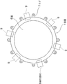
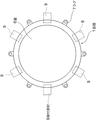
図1及び図2において、符号1で示されるものは有底形の容器であり、この容器1の開口2の輪状周縁部3の下面には、突起状をなす第2輪状係合部4が形成されている。
前記開口2の輪状周縁部3上には、グラスライニングGを施工したプロテクターリング5が載置して設けられ、このプロテクターリング5上には蓋6が設けられている。
前記プロテクターリング5の外周には、複数のラグ7が外方へ向けて突出して設けられている。前記蓋6の周縁上には第1輪状係合部8が設けられている。
DESCRIPTION OF EMBODIMENTS Hereinafter, preferred embodiments of a container clamping structure according to the present invention will be described with reference to the drawings.
Note that the same or equivalent parts as in the conventional example will be described using the same reference numerals.
1 and 2, what is indicated by
A protector ring 5 having a glass lining G applied thereon is placed on the ring-shaped peripheral edge 3 of the opening 2, and a
A plurality of lugs 7 are provided on the outer periphery of the protector ring 5 so as to protrude outward. A first ring-shaped engagement portion 8 is provided on the periphery of the
前記プロテクターリング5の周縁に形成された第1周縁段部20と前記蓋6との間には、第1Oリング21と四角形でテフロン(登録商標)、ポリプロピレン、塩化ビニール等からなる第1弾性介装体22が設けられ、この第1弾性介装体22はL字型の弾性材からなる第1弾性抑え体23によって第1周縁段部20の周縁に保持されている。
A first O-ring 21 and a quadrangular first Teflon (registered trademark), polypropylene, vinyl chloride, etc. are formed between the first peripheral step 20 formed on the periphery of the protector ring 5 and the
前述の図2の構成において、クランプ又はボルトと金具等の組合せからなる周知の締付部材9によって、第1輪状係合部8の外側及び前記第2輪状係合部4の外側を挟持するように締付けることにより、容器1の開口2に対してプロテクターリング5が第1Oリング21及び第1弾性介装体22を介して弾性的に押圧され完全なシールが行われる。
尚、前述の場合、前記、第1Oリング8の上面及び第1弾性介装体22の上面はプロテクターリング5の上面5aよりも若干高くなるように構成されている。
In the configuration of FIG. 2 described above, the outer side of the first ring-shaped engaging portion 8 and the outer side of the second ring-shaped engaging portion 4 are clamped by a known tightening
In the above-described case, the upper surface of the first O-ring 8 and the upper surface of the first elastic intervention body 22 are configured to be slightly higher than the upper surface 5 a of the protector ring 5.
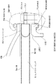
図3及び図4は図2の他の形態を示し、図2と同一部分には同一符号を付してその説明を省略し、図2と異なる部分についてのみ説明する。
すなわち、前記プロテクターリング5の下面5bにも前述と同様の第2周縁段部20aが形成され、この第2周縁段部20aにも前述と同様の第2Oリング21a及び第2弾性介装体22aが設けられ、前記各弾性介装体22,22aはL字型の第2弾性抑え体23aによって前記第1、第2周縁段部20,20aに押圧保持されている。
3 and 4 show another form of FIG. 2, the same parts as those of FIG. 2 are denoted by the same reference numerals, and the description thereof is omitted, and only the parts different from FIG. 2 will be described.
That is, a second peripheral step 20a similar to the above is also formed on the lower surface 5b of the protector ring 5, and the second O-ring 21a and the second elastic intermediate body 22a similar to the above are also formed on the second peripheral step 20a. The elastic interposing bodies 22 and 22a are pressed and held on the first and second peripheral stepped portions 20 and 20a by an L-shaped second elastic restraining body 23a.
前記各周縁段部20、20aは、断面でみてT字型をなしているため、一対の前記各Oリング21,21a及び各弾性介装体22,22aは前記各周縁段部20、20aに対して極めて良好な状態で位置決めできる。
尚、前記各弾性介装体22、22aは、平面で見てプロテクターリング5の周縁に保持されている。
Since each of the peripheral stepped portions 20 and 20a has a T shape in cross section, the pair of the O-rings 21 and 21a and the elastic intermediate bodies 22 and 22a are connected to the peripheral stepped portions 20 and 20a. On the other hand, positioning can be performed in a very good state.
Each of the elastic intermediate bodies 22 and 22a is held on the periphery of the protector ring 5 when viewed in plan.
従って、前述の図2の構成においては、前記第1周縁段部20上に第1Oリング21と第1弾性介装体22が設けられているため、前記第1輪状係合部8と前記第2輪状係合部4とを締付部材9で簡単、迅速かつ確実に締結又は締結解除でき、さらに、蓋6の開閉かつ洗浄等も容易となる。
また、図3及び図4の他の構成についても、前記プロテクターリング5の両面に一対のOリング21,21aを用いており、図2の構成よりもより確実にシールリング作用及び効果を得ることができる。
Therefore, in the configuration of FIG. 2 described above, since the first O-ring 21 and the first elastic intermediary body 22 are provided on the first peripheral step 20, the first annular engagement portion 8 and the first The two-wheel engaging portion 4 can be easily or quickly and reliably fastened or unfastened by the
3 and 4 also employs a pair of O-rings 21 and 21a on both sides of the protector ring 5, so that the seal ring action and effects can be obtained more reliably than the configuration of FIG. Can do.
本発明による容器のクランプ構造は、容器の開口に設けたプロテクターリング5の片面又は両面にOリングと介装体を設けることにより、あらゆる容器の蓋による簡単、迅速、確実にシール又はシール解除できる。 The container clamping structure according to the present invention can be easily or quickly sealed and unsealed by the lid of any container by providing an O-ring and an interposer on one or both sides of the protector ring 5 provided in the opening of the container. .
1 容器
2 開口
3 輪状周縁部
4 第2輪状係合部
5 プロテクターリング
G グラスライニング
5a 上面
5b 下面
6 蓋
7 ラグ
8 第1輪状係合部
9 締付部材
10 ボルト
11 止め金具
20 第1周縁段部
20a 第2周縁段部
21 第1Oリング
21a 第2Oリング
22 第1弾性介装体
22a 第2弾性介装体
23 第1弾性抑え体
23a 第2弾性抑え体
DESCRIPTION OF
Claims (3)
前記プロテクターリング(5)の第1周縁段部(20)と前記蓋(6)との間には、第1Oリング(21)と第1弾性介装体(22)が設けられていることを特徴とする容器のクランプ構造。 A container (1) having an opening (2) in the upper part, a ring-shaped peripheral part (3) having a second ring-shaped engaging part (4) formed on the peripheral part of the opening (2) and projecting downward; A protector ring (5) provided on the ring-shaped peripheral edge (3), a lid (6) provided on the protector ring (5), and a first ring provided on the peripheral edge of the lid (6) Engaging with the engaging portion (8), the first annular engaging portion (8) and the second annular engaging portion (4), the lid (6), the protector ring (5) and the annular peripheral portion In the clamping structure of the container comprising the clamping member (9) for sandwiching (3),
A first O-ring (21) and a first elastic intermediate body (22) are provided between the first peripheral step (20) of the protector ring (5) and the lid (6). Characteristic container clamp structure.
Priority Applications (1)
| Application Number | Priority Date | Filing Date | Title |
|---|---|---|---|
| JP2013041599A JP6153244B2 (en) | 2013-03-04 | 2013-03-04 | Container clamp structure |
Applications Claiming Priority (1)
| Application Number | Priority Date | Filing Date | Title |
|---|---|---|---|
| JP2013041599A JP6153244B2 (en) | 2013-03-04 | 2013-03-04 | Container clamp structure |
Publications (2)
| Publication Number | Publication Date |
|---|---|
| JP2014169105A true JP2014169105A (en) | 2014-09-18 |
| JP6153244B2 JP6153244B2 (en) | 2017-06-28 |
Family
ID=51691834
Family Applications (1)
| Application Number | Title | Priority Date | Filing Date |
|---|---|---|---|
| JP2013041599A Active JP6153244B2 (en) | 2013-03-04 | 2013-03-04 | Container clamp structure |
Country Status (1)
| Country | Link |
|---|---|
| JP (1) | JP6153244B2 (en) |
Cited By (2)
| Publication number | Priority date | Publication date | Assignee | Title |
|---|---|---|---|---|
| CN105672842A (en) * | 2016-03-17 | 2016-06-15 | 安徽恒意环保科技有限公司 | Manhole door for desulfurizing tower |
| JP2019522602A (en) * | 2016-07-21 | 2019-08-15 | ボド リヒターRICHTER, Bodo | Waste water container and manufacturing method thereof |
Citations (6)
| Publication number | Priority date | Publication date | Assignee | Title |
|---|---|---|---|---|
| US4361331A (en) * | 1979-10-22 | 1982-11-30 | Balzers Aktiengesellschaft fur Hochvakuumtechnic und Dunne Schichten | Seal for vacuum flange connections |
| JPH03111999U (en) * | 1990-02-28 | 1991-11-15 | ||
| US6139026A (en) * | 1999-03-25 | 2000-10-31 | Pfaudler, Inc. | Stabilized "O" ring gasket seal |
| US6402159B1 (en) * | 1997-04-08 | 2002-06-11 | Gary A. Kohn | Dielectric gasket |
| JP2003222243A (en) * | 2001-11-22 | 2003-08-08 | Shinko Pantec Co Ltd | Gasket, manhole structure, vessel, usage of vessel and operation auxiliary mechanism for hook portion |
| JP2006206107A (en) * | 2005-01-28 | 2006-08-10 | Kobelco Eco-Solutions Co Ltd | Manhole structure |
-
2013
- 2013-03-04 JP JP2013041599A patent/JP6153244B2/en active Active
Patent Citations (6)
| Publication number | Priority date | Publication date | Assignee | Title |
|---|---|---|---|---|
| US4361331A (en) * | 1979-10-22 | 1982-11-30 | Balzers Aktiengesellschaft fur Hochvakuumtechnic und Dunne Schichten | Seal for vacuum flange connections |
| JPH03111999U (en) * | 1990-02-28 | 1991-11-15 | ||
| US6402159B1 (en) * | 1997-04-08 | 2002-06-11 | Gary A. Kohn | Dielectric gasket |
| US6139026A (en) * | 1999-03-25 | 2000-10-31 | Pfaudler, Inc. | Stabilized "O" ring gasket seal |
| JP2003222243A (en) * | 2001-11-22 | 2003-08-08 | Shinko Pantec Co Ltd | Gasket, manhole structure, vessel, usage of vessel and operation auxiliary mechanism for hook portion |
| JP2006206107A (en) * | 2005-01-28 | 2006-08-10 | Kobelco Eco-Solutions Co Ltd | Manhole structure |
Cited By (3)
| Publication number | Priority date | Publication date | Assignee | Title |
|---|---|---|---|---|
| CN105672842A (en) * | 2016-03-17 | 2016-06-15 | 安徽恒意环保科技有限公司 | Manhole door for desulfurizing tower |
| JP2019522602A (en) * | 2016-07-21 | 2019-08-15 | ボド リヒターRICHTER, Bodo | Waste water container and manufacturing method thereof |
| JP7061108B2 (en) | 2016-07-21 | 2022-04-27 | ボド リヒター | Wastewater container and its manufacturing method |
Also Published As
| Publication number | Publication date |
|---|---|
| JP6153244B2 (en) | 2017-06-28 |
Similar Documents
| Publication | Publication Date | Title |
|---|---|---|
| JP6153244B2 (en) | Container clamp structure | |
| FR2427267A1 (en) | SET INCLUDING A CONTAINER AND ITS LID | |
| CN101360935A (en) | Sealing construction of pressure vessel | |
| TR201815568T4 (en) | Radiator element with a hook closing cover and associated radiator. | |
| JP2006226476A (en) | Man-hole sealing structure for pressure vessel | |
| RU2010150199A (en) | POT | |
| RU2014128024A (en) | COVER ASSEMBLY WITH TRANSITIONAL DEVICE, COVER AND SEALING FILM FOR CAPACITY | |
| US6824140B2 (en) | Manway cover gasket | |
| JP2016199323A (en) | Sealing container with medium/large capacity | |
| JP4476829B2 (en) | Manhole structure in glass-lined containers | |
| US1480544A (en) | Closure fastener | |
| CN202349231U (en) | Flange gasket for butterfly valves | |
| MX2021000003A (en) | Re-sealable can lid. | |
| CN203975651U (en) | Urea tank pilfer proof closure | |
| JP4982452B2 (en) | gasket | |
| US20080251521A1 (en) | Package for Two Components | |
| US512349A (en) | Fruit-jar | |
| US2543822A (en) | Closure for containers | |
| KR20170002178U (en) | Auxiliary stopper for sealing container | |
| JP2009137622A (en) | Sealing unit | |
| GB190212597A (en) | ||
| KR200476474Y1 (en) | Cover structure of storage tank | |
| RU2552774C2 (en) | Safety plug | |
| US696113A (en) | Jar cover and fastener. | |
| MX370401B (en) | Packaging container for automotive parts. |
Legal Events
| Date | Code | Title | Description |
|---|---|---|---|
| A621 | Written request for application examination |
Free format text: JAPANESE INTERMEDIATE CODE: A621 Effective date: 20160212 |
|
| A977 | Report on retrieval |
Free format text: JAPANESE INTERMEDIATE CODE: A971007 Effective date: 20161011 |
|
| A131 | Notification of reasons for refusal |
Free format text: JAPANESE INTERMEDIATE CODE: A131 Effective date: 20161025 |
|
| A521 | Request for written amendment filed |
Free format text: JAPANESE INTERMEDIATE CODE: A523 Effective date: 20161215 |
|
| TRDD | Decision of grant or rejection written | ||
| A01 | Written decision to grant a patent or to grant a registration (utility model) |
Free format text: JAPANESE INTERMEDIATE CODE: A01 Effective date: 20170509 |
|
| A61 | First payment of annual fees (during grant procedure) |
Free format text: JAPANESE INTERMEDIATE CODE: A61 Effective date: 20170529 |
|
| R150 | Certificate of patent or registration of utility model |
Ref document number: 6153244 Country of ref document: JP Free format text: JAPANESE INTERMEDIATE CODE: R150 |
|
| R250 | Receipt of annual fees |
Free format text: JAPANESE INTERMEDIATE CODE: R250 |
|
| S533 | Written request for registration of change of name |
Free format text: JAPANESE INTERMEDIATE CODE: R313533 |
|
| R350 | Written notification of registration of transfer |
Free format text: JAPANESE INTERMEDIATE CODE: R350 |
|
| R250 | Receipt of annual fees |
Free format text: JAPANESE INTERMEDIATE CODE: R250 |
|
| R250 | Receipt of annual fees |
Free format text: JAPANESE INTERMEDIATE CODE: R250 |
|
| R250 | Receipt of annual fees |
Free format text: JAPANESE INTERMEDIATE CODE: R250 |