JP2014148940A - Control device of internal combustion engine with supercharger - Google Patents
Control device of internal combustion engine with supercharger Download PDFInfo
- Publication number
- JP2014148940A JP2014148940A JP2013018451A JP2013018451A JP2014148940A JP 2014148940 A JP2014148940 A JP 2014148940A JP 2013018451 A JP2013018451 A JP 2013018451A JP 2013018451 A JP2013018451 A JP 2013018451A JP 2014148940 A JP2014148940 A JP 2014148940A
- Authority
- JP
- Japan
- Prior art keywords
- passage
- compressor
- flow path
- exhaust gas
- egr
- Prior art date
- Legal status (The legal status is an assumption and is not a legal conclusion. Google has not performed a legal analysis and makes no representation as to the accuracy of the status listed.)
- Pending
Links
Images


Classifications
-
- Y—GENERAL TAGGING OF NEW TECHNOLOGICAL DEVELOPMENTS; GENERAL TAGGING OF CROSS-SECTIONAL TECHNOLOGIES SPANNING OVER SEVERAL SECTIONS OF THE IPC; TECHNICAL SUBJECTS COVERED BY FORMER USPC CROSS-REFERENCE ART COLLECTIONS [XRACs] AND DIGESTS
- Y02—TECHNOLOGIES OR APPLICATIONS FOR MITIGATION OR ADAPTATION AGAINST CLIMATE CHANGE
- Y02T—CLIMATE CHANGE MITIGATION TECHNOLOGIES RELATED TO TRANSPORTATION
- Y02T10/00—Road transport of goods or passengers
- Y02T10/10—Internal combustion engine [ICE] based vehicles
- Y02T10/12—Improving ICE efficiencies
Abstract
Description
この発明は、過給機付き内燃機関の制御装置に関する。 The present invention relates to a control device for an internal combustion engine with a supercharger.
従来、例えば特許文献1には、ターボ過給機付き内燃機関の排気浄化システムが開示されている。この従来の内燃機関は、ターボ過給機のタービンよりも下流(より具体的には、タービン下流の排気浄化装置の更に下流)側の排気通路とコンプレッサよりも上流側の吸気通路とを接続する低圧EGR通路(低圧排気ガス還流通路)を備えている。また、上記内燃機関は、コンプレッサによって加圧された吸気の一部を、EGRクーラーに対してEGRガス(再循環排気ガス)導入時のEGRガス流れの下流側の低圧EGR通路に導くためのバイパス通路を備えている。そして、上記内燃機関では、EGRガスの導入を行わない場合に、バイパス通路を介して加圧された吸気の一部を低圧EGR通路の下流から上流へ逆流させることで、EGR通路およびEGRクーラー内に滞留している未燃燃料や凝縮水を吹き飛ばし、除去することとしている。 Conventionally, for example, Patent Document 1 discloses an exhaust gas purification system for an internal combustion engine with a turbocharger. This conventional internal combustion engine connects an exhaust passage downstream of the turbine of the turbocharger (more specifically, further downstream of the exhaust gas purification device downstream of the turbine) and an intake passage upstream of the compressor. A low pressure EGR passage (low pressure exhaust gas recirculation passage) is provided. Further, the internal combustion engine has a bypass for guiding a part of the intake air pressurized by the compressor to the low pressure EGR passage on the downstream side of the EGR gas flow when EGR gas (recirculation exhaust gas) is introduced into the EGR cooler. It has a passage. In the internal combustion engine, when the EGR gas is not introduced, a part of the intake air pressurized via the bypass passage is caused to flow backward from the downstream of the low pressure EGR passage to the upstream of the EGR passage and the EGR cooler. The unburned fuel and the condensed water staying in are blown off and removed.
上記特許文献1に記載の内燃機関のように、コンプレッサよりも上流側の吸気通路に対してEGRガスを導入可能な構成(低圧EGR装置)を備えている場合には、コンプレッサの上流においてEGRガスと新気とが合流することになる。EGRガスは水分を多く含んでおり、新気は、通常、EGRガスよりも温度が低い。このため、EGRガスが新気と合流した際に、EGRガスが新気によって冷却され、凝縮水が発生し易くなる。発生した凝縮水はコンプレッサに吸入される。特に、軽負荷時には、吸気通路内の吸気の流速が低いため、発生した凝縮水が吸気通路内に長く留まって粒径の大きな水滴となったうえでコンプレッサに吸入される可能性が高くなる。このようなコンプレッサへの凝縮水の流入によって、過給機の性能低下が生ずることが懸念される。 In the case where an EGR gas can be introduced into the intake passage upstream of the compressor (low pressure EGR device) as in the internal combustion engine described in Patent Document 1, the EGR gas is disposed upstream of the compressor. And new energy will join. EGR gas contains a lot of moisture, and fresh air usually has a lower temperature than EGR gas. For this reason, when EGR gas merges with fresh air, the EGR gas is cooled by fresh air, and condensed water is easily generated. The generated condensed water is sucked into the compressor. In particular, when the load is light, since the flow velocity of the intake air in the intake passage is low, the generated condensed water stays in the intake passage for a long time and becomes a droplet having a large particle size, and is more likely to be sucked into the compressor. There is a concern that the performance of the supercharger may deteriorate due to the inflow of condensed water into the compressor.
この発明は、上述のような課題を解決するためになされたもので、再循環排気ガスと新気との合流によって生ずる凝縮水による過給機の性能低下を防止しつつ、運転領域を問わずに低圧排気ガス還流通路を利用した再循環排気ガスの導入を可能とする過給機付き内燃機関の制御装置を提供することを目的とする。 The present invention has been made to solve the above-described problems, and prevents deterioration of the performance of the supercharger due to condensed water caused by confluence of recirculated exhaust gas and fresh air, regardless of the operation region. Another object of the present invention is to provide a control device for an internal combustion engine with a supercharger that enables introduction of recirculated exhaust gas using a low pressure exhaust gas recirculation passage.
第1の発明は、過給機付き内燃機関の制御装置であって、
吸気通路に配置されたコンプレッサと、排気通路に配置されたタービンとを有するターボ過給機と、
前記タービンよりも下流側の前記排気通路と前記コンプレッサよりも上流側の前記吸気通路であるコンプレッサ上流側吸気通路とを接続する低圧排気ガス還流通路と、
前記低圧排気ガス還流通路の途中から分岐し、前記コンプレッサよりも下流側の前記吸気通路であるコンプレッサ下流側吸気通路に接続されるバイパス通路と、
前記排気通路から前記低圧排気ガス還流通路を導入される再循環排気ガスの流路形態を、当該再循環排気ガスが前記低圧排気ガス還流通路を通って前記コンプレッサ上流側吸気通路に導入される第1流路形態と、当該再循環排気ガスが前記低圧排気ガス還流通路および前記バイパス通路を順に通って前記コンプレッサ下流側吸気通路に導入される第2流路形態との間で選択可能な流路切替手段と、
前記コンプレッサの下流側の吸気圧力に応じて、前記第1流路形態と前記第2流路形態との間で前記流路形態が切り替わるように前記流路切替手段を制御する流路制御手段と、
を備えることを特徴とする。
1st invention is a control apparatus of the internal combustion engine with a supercharger,
A turbocharger having a compressor disposed in the intake passage and a turbine disposed in the exhaust passage;
A low-pressure exhaust gas recirculation passage connecting the exhaust passage downstream of the turbine and the compressor upstream intake passage which is the intake passage upstream of the compressor;
A bypass passage branched from the middle of the low-pressure exhaust gas recirculation passage and connected to a compressor downstream intake passage which is the intake passage downstream of the compressor;
The recirculated exhaust gas is introduced into the low pressure exhaust gas recirculation passage from the exhaust passage, and the recirculation exhaust gas is introduced into the compressor upstream intake passage through the low pressure exhaust gas recirculation passage. A flow path that is selectable between one flow path form and a second flow path form in which the recirculated exhaust gas passes through the low-pressure exhaust gas recirculation passage and the bypass passage and is introduced into the compressor downstream intake passage. Switching means;
A flow path control means for controlling the flow path switching means so that the flow path form is switched between the first flow path form and the second flow path form in accordance with an intake pressure downstream of the compressor; ,
It is characterized by providing.
また、第2の発明は、第1の発明において、
前記流路制御手段は、前記コンプレッサの下流側の吸気圧力が所定値以下となる場合に、前記第2流路形態が選択されるように前記流路切替手段を制御し、前記コンプレッサの下流側の吸気圧力が前記所定値よりも高い場合に、前記第1流路形態が選択されるように前記流路切替手段を制御するものであることを特徴とする。
The second invention is the first invention, wherein
The flow path control means controls the flow path switching means so that the second flow path configuration is selected when the intake pressure downstream of the compressor is equal to or lower than a predetermined value, and the downstream side of the compressor The flow path switching means is controlled so that the first flow path configuration is selected when the intake pressure of the air is higher than the predetermined value.
また、第3の発明は、第1または第2の発明において、
前記吸気通路に再循環排気ガスを導入しない場合であって、前記コンプレッサの下流側の吸気圧力が前記タービンの下流側の排気圧力よりも高い場合に、前記バイパス通路を開放させるバイパス通路開放手段を更に備えることを特徴とする。
The third invention is the first or second invention, wherein
Bypass passage opening means for opening the bypass passage when recirculated exhaust gas is not introduced into the intake passage and the intake pressure downstream of the compressor is higher than the exhaust pressure downstream of the turbine; It is further provided with the feature.
また、第4の発明は、第3の発明において、
前記バイパス通路との分岐位置よりも前記排気通路に近い側において前記低圧排気ガス還流通路に配置され、当該低圧排気ガス還流通路を流れる再循環排気ガスを冷却するクーラーを更に備えることを特徴とする。
Moreover, 4th invention is set in 3rd invention,
The apparatus further comprises a cooler that is disposed in the low pressure exhaust gas recirculation passage closer to the exhaust passage than a branch position with the bypass passage and cools the recirculated exhaust gas flowing through the low pressure exhaust gas recirculation passage. .
第1および第2の発明によれば、コンプレッサの下流側の吸気圧力(以下、「コンプレッサ下流圧」と略する)に応じて、上記第1流路形態と上記第2流路形態との間で再循環排気ガスの流路形態が切り替わるように流路切替手段を制御する流路制御手段を備えていることにより、次のような効果が得られる構成を実現することができる。すなわち、軽負荷側の非過給領域のようにコンプレッサ下流圧が低い場合に第2流路形態が選択されるように流路切替手段を制御することで、コンプレッサの下流側において再循環排気ガスと新気との混合が行われるようにすることができる。このため、コンプレッサの上流側での凝縮水の発生を回避することで、凝縮水の流入を原因としてコンプレッサに損傷や腐食が生ずるのを防止することができる。また、高負荷側の過給領域のようにコンプレッサ下流圧が高い場合に第1流路形態が選択されるように流路切替手段を制御することで、過給領域であっても再循環排気ガスの導入を行えるようになる。この場合には、コンプレッサの上流側で再循環排気ガスと新気とが混合するため、凝縮水が発生してコンプレッサに流入する可能性がある。しかしながら、高負荷側の過給領域では、コンプレッサの上流における吸入空気量流量が多いため、凝縮水が発生した場合であっても凝縮水は吸気通路に留まることなく粒径の小さな液滴のままで速やかにコンプレッサに吸入されることとなる。このため、この場合には、コンプレッサは、凝縮水の流入を原因とする損傷等を受けにくいといえる。
以上のように、本発明によれば、再循環排気ガスと新気との合流によって生ずる凝縮水による過給機の性能低下を防止しつつ、運転領域を問わずに低圧排気ガス還流通路を利用した再循環排気ガスの導入を可能とすることができる。
According to the first and second inventions, between the first flow path configuration and the second flow path configuration according to the intake pressure downstream of the compressor (hereinafter abbreviated as “compressor downstream pressure”). By providing the flow path control means for controlling the flow path switching means so that the flow path configuration of the recirculated exhaust gas is switched, a configuration in which the following effects can be obtained can be realized. That is, by controlling the flow path switching means so that the second flow path configuration is selected when the compressor downstream pressure is low as in the non-supercharged area on the light load side, the recirculated exhaust gas on the downstream side of the compressor And fresh air can be mixed. For this reason, by avoiding the generation of condensed water on the upstream side of the compressor, it is possible to prevent the compressor from being damaged or corroded due to the inflow of condensed water. Further, by controlling the flow path switching means so that the first flow path configuration is selected when the compressor downstream pressure is high as in the supercharge area on the high load side, recirculation exhaust is performed even in the supercharge area. Gas can be introduced. In this case, since the recirculated exhaust gas and fresh air are mixed on the upstream side of the compressor, condensed water may be generated and flow into the compressor. However, in the supercharge region on the high load side, since the intake air flow rate is large upstream of the compressor, even if condensed water is generated, the condensed water does not stay in the intake passage and remains as a small droplet with a small particle diameter. It will be immediately sucked into the compressor. Therefore, in this case, it can be said that the compressor is not easily damaged due to the inflow of condensed water.
As described above, according to the present invention, the low-pressure exhaust gas recirculation passage is used regardless of the operation region while preventing the deterioration of the performance of the supercharger due to the condensed water caused by the combined recirculation exhaust gas and fresh air. It is possible to introduce the recirculated exhaust gas.
第3の発明によれば、吸気通路に再循環排気ガスを導入しない状況下において、コンプレッサにより過給された吸気(新気)を低圧排気ガス還流通路に導入することができる。その結果、低圧排気ガス還流通路を排気通路側に向かって逆流する高圧の吸気によって、低圧排気ガス還流通路の内壁に付着している未燃燃料および凝縮水を吹き飛ばして除去することができる。このように、本発明によれば、低圧排気ガス還流通路の掃気を行うことができるので、未燃燃料および凝縮水の滞留による低圧排気ガス還流通路の圧力損失の増加等の不具合を防止することが可能となる。 According to the third aspect of the present invention, the intake air (fresh air) supercharged by the compressor can be introduced into the low-pressure exhaust gas recirculation passage in a situation where the recirculation exhaust gas is not introduced into the intake passage. As a result, unburned fuel and condensed water adhering to the inner wall of the low-pressure exhaust gas recirculation passage can be blown off by the high-pressure intake air that flows backward through the low-pressure exhaust gas recirculation passage toward the exhaust passage. As described above, according to the present invention, since the scavenging of the low pressure exhaust gas recirculation passage can be performed, problems such as an increase in the pressure loss of the low pressure exhaust gas recirculation passage due to retention of unburned fuel and condensed water can be prevented. Is possible.
第4の発明によれば、吸気通路に再循環排気ガスを導入しない状況下において、コンプレッサにより過給された吸気(新気)を利用して、再循環排気ガスの冷却のためのクーラーをも掃気することができる。これにより、未燃燃料および凝縮水の滞留による当該クーラーの性能低下をも防止することができる。 According to the fourth aspect of the invention, in a situation where the recirculated exhaust gas is not introduced into the intake passage, the cooler for cooling the recirculated exhaust gas is provided using the intake air (fresh air) supercharged by the compressor. Can be scavenged. Thereby, the performance fall of the said cooler by the stay of unburned fuel and condensed water can also be prevented.
実施の形態1.
[実施の形態1のシステム構成]
図1は、本発明の実施の形態1の内燃機関10のシステム構成を説明するための図である。図1に示すシステムは、内燃機関10を備えている。ここでは、内燃機関10は、一例として火花点火式であり、車両に搭載され、その動力源とされるものである。本実施形態の内燃機関10は、一例として直列4気筒型のものを表しているが、本発明における内燃機関の気筒数および気筒配置はこれに限定されるものではない。内燃機関10は、空気を筒内に取り込むための吸気通路12と、筒内から排気ガスを排出するための排気通路14とを備えている。
Embodiment 1 FIG.
[System Configuration of Embodiment 1]
FIG. 1 is a diagram for explaining a system configuration of an
吸気通路12の入口近傍には、エアクリーナ16が設けられている。エアクリーナ16の下流には、吸気通路12に吸入される空気の流量に応じた信号を出力するエアフローメータ18が設けられている。エアフローメータ18の下流には、ターボ過給機20のコンプレッサ20aが配置されている。ターボ過給機20は、コンプレッサ20aと一体的に連結され排気ガスの排気エネルギによって作動するタービン20bを備えている。コンプレッサ20aは、タービン20bに入力される排気ガスの排気エネルギによって回転駆動される。
An
更に、コンプレッサ20aよりも下流側の吸気通路12(以下、「コンプレッサ下流側吸気通路12b」と称する)には、コンプレッサ20aにより圧縮された空気を冷却するためのインタークーラー22が配置されている。更に、インタークーラー22の下流には、吸気通路12を流れる空気量を調整するためのスロットルバルブ24が配置されている。スロットルバルブ24は、図示省略するスロットルモータにより駆動される電子制御式のバルブである。スロットルバルブ24の下流には、サージタンク26が配置されている。また、コンプレッサ下流側吸気通路12b(より具体的には、コンプレッサ20aとインタークーラー22との間)には、コンプレッサ20aの下流側の吸気圧力(以下、「コンプレッサ下流圧」と略する)を検出するための吸気圧力センサ28が取り付けられている。
Furthermore, an
ターボ過給機20のタービン20bは、排気通路14の途中に配置されている。タービン20bよりも上流側の排気通路14には、排気ガスを浄化するための排気浄化装置として、上流側から順に、上流触媒(S/C:Start Catalyst)30および下流触媒(UF/C:Underfloor Catalyst)32がそれぞれ配置されている。上流触媒30の下流(より具体的には、上流触媒30と下流触媒32との間)の排気通路14には、その部位での排気圧力(タービン下流圧でもあり、以下、「S/C下流圧」と称する)を検出するための排気圧力センサ34が取り付けられている。
The
また、図1に示すシステムは、低圧排気ガス還流通路(LPL(Low Pressure Loop)−EGR通路)36を備えている。LPL−EGR通路36は、タービン20bよりも下流側(本実施形態では、更に上流触媒30よりも下流側)の排気通路14とコンプレッサ20aよりも上流側の吸気通路12(以下、「コンプレッサ上流側吸気通路12a」と称する)とを連通するように構成されている。このLPL−EGR通路36の途中には、LPL−EGR通路36を通って吸気通路12に再循環排気ガス(EGRガス)を導入する際のEGRガス流れの上流側(すなわち、排気通路14に近い側)から順に、EGRクーラー38およびEGRバルブ40がそれぞれ配置されている。EGRクーラー38は、LPL−EGR通路36に導入された排気ガス(EGRガス)を冷却するために備えられている。EGRバルブ40は、LPL−EGR通路36の開閉を担うバルブであり、より具体的には、LPL−EGR通路36の流路断面積を変更することによってLPL−EGR通路36を介して吸気通路12に導入されるEGRガスの流量を調整するためのバルブである。
Further, the system shown in FIG. 1 includes a low pressure exhaust gas recirculation passage (LPL (Low Pressure Loop) -EGR passage) 36. The LPL-
更に、図1に示すシステムは、EGRバルブ40よりもEGRガス流れの下流側においてLPL−EGR通路36の途中から分岐し、コンプレッサ下流側吸気通路12bに接続されるバイパス通路42を備えている。LPL−EGR通路36におけるバイパス通路42との分岐位置には、バイパスバルブ44が配置されている。
Further, the system shown in FIG. 1 includes a
バイパスバルブ44は、EGRバルブ40を開くことによりLPL−EGR通路36を用いたEGRガスの導入を行う状況下において、EGRガスの流路形態を、EGRガスがLPL−EGR通路36をそのまま通ってコンプレッサ上流側吸気通路12aに導入される第1流路形態と、EGRガスがLPL−EGR通路36およびバイパス通路42を順に通ってコンプレッサ下流側吸気通路12bに導入される第2流路形態との間で選択可能とするためのバルブである。
The
すなわち、バイパスバルブ44によって第1流路形態が選択された場合には、上記分岐位置を通過した後のEGRガスは、図1中に「経路B」と付して示すLPL−EGR通路36内の部位を通ってコンプレッサ上流側吸気通路12aに導入されることになる。この場合に、EGRバルブ40の開度を調整することで、LPL−EGR通路36(経路B)を通ってコンプレッサ上流側吸気通路12aに還流されるEGRガスの流量を調整することができる。一方、第2流路形態が選択された場合には、上記分岐位置を通過した後のEGRガスは、図1中に「経路A」と付して示すバイパス通路42を通ってコンプレッサ下流側吸気通路12bに導入されることになる。この場合においても、EGRバルブ40の開度を調整することで、LPL−EGR通路36およびバイパス通路42(経路A)を通ってコンプレッサ下流側吸気通路12bに還流されるEGRガスの流量を調整することができる。
That is, when the first flow path form is selected by the
本実施形態のシステムは、更に、ECU(Electronic Control Unit)46を備えている。ECU46の入力部には、上述したエアフローメータ18、吸気圧力センサ28、排気圧力センサ34とともに、エンジン回転数を検出するためのクランク角センサ(図示省略)等の内燃機関10の運転状態を検出するための各種のセンサが接続されている。また、ECU46の出力部には、上述したスロットルバルブ24、EGRバルブ40およびバイパスバルブ44とともに、図示省略する燃料噴射弁および点火プラグ等の内燃機関10の運転を制御するための各種のアクチュエータが接続されている。ECU46は、上記各種のセンサ出力と所定のプログラムとに基づいて上記各種のアクチュエータを駆動することにより、内燃機関10の運転を制御するものである。
The system of this embodiment further includes an ECU (Electronic Control Unit) 46. The input portion of the
[コンプレッサの上流へのEGRガス導入に関する課題]
本実施形態の内燃機関10のように、コンプレッサ上流側吸気通路12aに対してEGRガスを導入可能な構成(LPL−EGR通路36を利用するEGR装置)を備えている場合には、コンプレッサ20aの上流においてEGRガスと新気とが合流することになる。EGRガスは水分を多く含んでいるため、新気と合流した際のガス温度が露点(含有水蒸気量が飽和水蒸気量と等しくなる時の温度)以下となると、凝縮水が発生する。新気は、通常、EGRガスよりも温度が低い。このため、EGRガスが新気と合流してEGRガスが新気によって冷やされた際に、ガス温度が露点以下となり、凝縮水が発生してしまう。
[Problems related to EGR gas introduction upstream of compressor]
As in the
発生した凝縮水はコンプレッサ20aに吸入される。コンプレッサ20aは高速で回転しているため、水滴との衝突によってコンプレッサホイールに損傷が生ずる可能性がある。コンプレッサホイールの損傷は、タービン効率の低下などのターボ過給機20の性能低下を招く可能性がある。コンプレッサホイールに衝突する水滴の粒径が大きい方が、コンプレッサホイールの損傷が生じ易くなる。特に、軽負荷時には、吸気通路12内の吸気の流速が低いため、発生した凝縮水が吸気通路12内に長く留まって粒径の大きな水滴に成長し易い。このため、粒径の大きな水滴がコンプレッサ20aに吸入される可能性が高くなり、ターボ過給機20の性能低下が生じ易くなることが懸念される。
The generated condensed water is sucked into the
[実施の形態1における特徴的な制御]
そこで、本実施形態では、LPL−EGR通路36を利用したEGRガスの導入要求が出された場合には、コンプレッサ下流圧に応じて、LPL−EGR通路36を利用してEGRガスを導入する際のEGRガスの流路形態を、上記の第1流路形態と第2流路形態との間で切り替えるようにした。より具体的には、コンプレッサ下流圧が大気圧以下である場合(すなわち、内燃機関10の運転領域が非過給領域である場合)には、コンプレッサ下流側吸気通路12bにEGRガスを導入する経路A(第2流路形態)が選択されるようにバイパスバルブ44を制御し、一方、コンプレッサ下流圧が大気圧よりも高い場合(すなわち、内燃機関10の運転領域が過給領域である場合)には、コンプレッサ上流側吸気通路12aにEGRガスを導入する経路B(第1流路形態)が選択されるようにバイパスバルブ44を制御するようにした。
[Characteristic Control in Embodiment 1]
Therefore, in the present embodiment, when an EGR gas introduction request using the LPL-
更に、本実施形態では、LPL−EGR通路36を利用したEGRガスの導入を行わない場合(例えば、EGRガスの導入中にEGR停止要求が出された場合)において、コンプレッサ下流圧がS/C下流圧よりも高い場合には、経路A(第2流路形態)が選択されるようにバイパスバルブ44を制御することでバイパス通路42を開放しつつ、かつ、所定時間Cが経過するまでEGRバルブ40を開くようにした。
Furthermore, in this embodiment, when the EGR gas is not introduced using the LPL-EGR passage 36 (for example, when an EGR stop request is issued during the introduction of the EGR gas), the compressor downstream pressure is S / C. When the pressure is higher than the downstream pressure, the
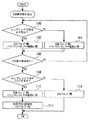
図2は、本発明の実施の形態1の特徴的な制御を実現するためにECU46が実行する制御ルーチンを示すフローチャートである。尚、本ルーチンは、LPL−EGR通路36を利用したEGRガスの導入を行う所定のEGR実行条件が成立した場合に開始されるものとする。
FIG. 2 is a flowchart showing a control routine executed by the
図2に示すルーチンでは、先ず、吸気圧力センサ28の出力を利用して、コンプレッサ下流圧が大気圧以下であるか否かが判定される(ステップ100)。 In the routine shown in FIG. 2, first, it is determined whether the downstream pressure of the compressor is equal to or lower than the atmospheric pressure using the output of the intake pressure sensor 28 (step 100).
その結果、上記ステップ100においてコンプレッサ下流圧が大気圧以下であると判定された場合、つまり、内燃機関10の運転領域が非過給領域であると判断できる場合には、経路Aが開かれる(第2流路形態が選択される)ようにバイパスバルブ44が制御されるとともに、要求EGRガス量を確保できる開度となるようにEGRバルブ40が制御される(ステップ102)。
As a result, when it is determined in
一方、上記ステップ100においてコンプレッサ下流圧が大気圧よりも高いと判定された場合、つまり、内燃機関10の運転領域が過給領域であると判断できる場合には、経路Bが開かれる(第1流路形態が選択される)ようにバイパスバルブ44が制御されるとともに、要求EGRガス量を確保できる開度となるようにEGRバルブ40が制御される(ステップ104)。
On the other hand, when it is determined in
次に、EGRガスの導入を停止するEGR停止要求が出されたか否かが判定される(ステップ106)。その結果、EGR停止要求が出されていない場合、つまり、LPL−EGR通路36を用いたEGRガスの導入を継続する場合には、上記ステップ100以降の処理が繰り返し実行される。
Next, it is determined whether or not an EGR stop request for stopping the introduction of EGR gas has been issued (step 106). As a result, when the EGR stop request is not issued, that is, when the introduction of the EGR gas using the LPL-
一方、上記ステップ106においてEGR停止要求が出されたと判定された場合には、次いで、吸気圧力センサ28および排気圧力センサ34の出力を利用して、コンプレッサ下流圧がS/C下流圧よりも高いか否かが判定される(ステップ108)。その結果、コンプレッサ下流圧がS/C下流圧以下であると判定された場合には、EGRバルブ40が全閉に制御される(ステップ110)。これにより、LPL−EGR通路36を介したガスの流通が遮断される。
On the other hand, if it is determined in
一方、上記ステップ108においてコンプレッサ下流圧がS/C下流圧よりも高いと判定された場合には、EGRバルブ40が開かれるとともに、経路Aが開放されるようにバイパスバルブ44が制御される(ステップ112)。これにより、コンプレッサ下流側吸気通路12bを流れる高圧の吸気(新気)の一部を、経路A(すなわち、バイパス通路42)を介して通常のEGRガス導入時のEGRガス流れとは逆方向でLPL−EGR通路36に導入することができる。
On the other hand, if it is determined in
次に、上記ステップ112の処理に伴うLPL−EGR通路36への新気の導入を開始してから所定時間Cが経過した場合には、EGRバルブ40が閉じられる(ステップ114)。これにより、LPL−EGR通路36への新気の導入が終了される。本ステップ114における所定時間Cは、上記ステップ112の処理によるLPL−EGR通路36への新気の導入の開始時点から、当該新気の導入に伴って吸気側のコンプレッサ下流圧よりも排気側のS/C下流圧が高くなることで当該新気の導入ができなくなる時点までの時間に相当する値として予め設定されたものである。
Next, when a predetermined time C has elapsed since the introduction of fresh air into the LPL-
以上説明した図2に示すルーチンによれば、LPL−EGR通路36を利用したEGRガスの導入要求が出された際に、コンプレッサ下流圧が大気圧以下である場合(すなわち、内燃機関10の運転領域が軽負荷領域などの非過給領域である場合)には、コンプレッサ下流側吸気通路12bにEGRガスを導入する経路A(第2流路形態)が選択されるようにバイパスバルブ44が制御される。これにより、コンプレッサ20aの下流側においてEGRガスと新気との混合が行われるようにすることができる。このため、コンプレッサ20aの上流側での凝縮水の発生を回避することで、凝縮水の流入を原因としてコンプレッサ20aに損傷や腐食が生ずるのを防止することができる。
According to the routine shown in FIG. 2 described above, when the EGR gas introduction request using the LPL-
また、上記ルーチンによれば、EGRガスの導入要求が出された際に、コンプレッサ下流圧が大気圧よりも高い場合(すなわち、内燃機関10の運転領域が過給領域である場合)には、コンプレッサ上流側吸気通路12aにEGRガスを導入する経路B(第1流路形態)が選択されるようにバイパスバルブ44が制御される。これにより、過給領域であっても、EGRガスの導入を行えるようになる。この場合には、コンプレッサ20aの上流側でEGRガスと新気とが混合するため、凝縮水が発生してコンプレッサ20aに流入する可能性がある。しかしながら、高負荷側の過給領域では、コンプレッサ20aの上流における吸入空気量流量が多いため、凝縮水が発生した場合であっても凝縮水は吸気通路12に留まることなく粒径の小さな液滴のままで速やかにコンプレッサ20aに吸入されることとなる。このため、この場合には、コンプレッサ20aは、凝縮水の流入を原因とする損傷等を受けにくいといえる。
Further, according to the above routine, when the EGR gas introduction request is issued and the compressor downstream pressure is higher than the atmospheric pressure (that is, when the operating region of the
以上のように、本実施形態のシステムによれば、LPL−EGR通路36に導入されるEGRガスの吸気通路12への流出先を、コンプレッサ下流圧に応じてコンプレッサ20aの上流と下流とに切り替えたことにより、EGRガスと新気との合流によって生ずる凝縮水によるターボ過給機20の性能低下を防止しつつ、運転領域を問わずにLPL−EGR通路36を利用したEGRガスの導入を可能とすることができる。
As described above, according to the system of this embodiment, the outflow destination of the EGR gas introduced into the LPL-
また、上記ルーチンによれば、LPL−EGR通路36を利用したEGRガスの導入を行わない場合(EGR停止要求が出された場合)において、コンプレッサ下流圧がS/C下流圧よりも高い場合には、経路A(第2流路形態)が選択されるようにバイパスバルブ44を制御することでバイパス通路42を開放しつつ、かつ、所定時間Cが経過するまでEGRバルブ40が開かれる。これにより、EGRガスを導入しない状況下において、コンプレッサ20aにより過給された吸気(新気)をLPL−EGR通路36、更にはEGRクーラー38に導入することができる。その結果、LPL−EGR通路36を排気通路14側に向かって逆流する高圧の吸気によって、LPL−EGR通路36およびEGRクーラー38の内壁に付着している未燃燃料および凝縮水を吹き飛ばして除去することができる。吹き飛ばされた未燃燃料および凝縮水は、LPL−EGR通路36から排気通路14に排出され、下流触媒32を通過する際に浄化されたうえで大気中に放出される。このように、上記制御によれば、LPL−EGR通路36、更にはLPL−EGR通路36に設けられたEGRクーラー38の掃気を行うことができるので、未燃燃料および凝縮水の滞留によるLPL−EGR通路36の圧力損失の増加およびEGRクーラー38の性能低下等の不具合を防止することが可能となる。
Further, according to the above routine, when the EGR gas is not introduced using the LPL-EGR passage 36 (when an EGR stop request is issued), the compressor downstream pressure is higher than the S / C downstream pressure. The
ところで、上述した実施の形態1においては、コンプレッサ下流圧が大気圧以下であるか否か(非過給領域であるか過給領域であるか)の判断結果に応じて、経路A(第2流路形態)と経路B(第1流路形態)との間でEGRガスの流路形態を切り替える例について説明を行った。しかしながら、本発明においてコンプレッサの下流側の吸気圧力に応じて再循環排気ガスの流路形態を切り替える際に用いる所定値は、大気圧に限らず、例えば、以下のように設定される過給圧Aであってもよい。 By the way, in the above-described first embodiment, the route A (second) is determined according to the determination result of whether the compressor downstream pressure is equal to or lower than the atmospheric pressure (whether it is a non-supercharging region or a supercharging region). An example of switching the EGR gas channel configuration between the channel configuration) and the path B (first channel configuration) has been described. However, in the present invention, the predetermined value used when switching the flow form of the recirculated exhaust gas in accordance with the intake pressure on the downstream side of the compressor is not limited to the atmospheric pressure, for example, the supercharging pressure set as follows: A may be sufficient.
すなわち、過給領域であっても、コンプレッサ下流圧があまり高くなっていない状況下であれば、コンプレッサ下流側吸気通路12bに対してEGRガスを導入可能な領域が存在する。そこで、過給領域であってもEGRガスを導入可能な限界となる領域に対してまではコンプレッサ20aの下流側に向けてのEGRガスの導入を行うようにするために、このような思想に基づいて設定する過給圧Aを上記所定値として用いるようにしてもよい。
That is, even in the supercharging region, there is a region where EGR gas can be introduced into the compressor downstream
図3は、本発明の実施の形態1の変形例においてECU46が実行する制御ルーチンを示すフローチャートである。
FIG. 3 is a flowchart showing a control routine executed by
図3に示すルーチンでは、先ず、コンプレッサ下流圧が上記過給圧A以下であるか否かが判定される(ステップ200)。この過給圧Aは、上記の思想に基づいて設定される値であり、過給領域においてコンプレッサ下流側吸気通路12bにLPL−EGR通路36を介してEGRガスを供給可能な過給圧の上限値に相当するものである。より具体的には、過給圧Aは、コンプレッサ下流圧とS/C下流圧との差圧と、要求EGRガス量とに基づいて決定される閾値であり、ECU46は、エンジン回転数とエンジン負荷との関係で過給圧Aを予めマップ化して記憶しておくことで、現在の運転状態に応じた過給圧Aを収録することができる。
In the routine shown in FIG. 3, it is first determined whether or not the compressor downstream pressure is equal to or lower than the supercharging pressure A (step 200). The supercharging pressure A is a value set based on the above-described concept, and the upper limit of the supercharging pressure at which EGR gas can be supplied to the compressor downstream
上記ステップ200においてコンプレッサ下流圧が過給圧A以下であると判定された場合には、ステップ102に進み、一方、コンプレッサ下流圧が過給圧Aよりも高いと判定された場合には、ステップ104に進む。尚、図3において、ステップ102もしくは104以降の処理については、実施の形態1における図2に示すルーチンの処理と同様であるため、ここでは、その詳細な説明を省略する。
When it is determined in
また、上述した実施の形態1においては、低圧排気ガス還流通路(LPL−EGR通路)36における排気側の接続口を、タービン20bの下流側であって、かつ上流触媒(S/C)30の下流側の排気通路14とした例について説明を行った。このような構成によれば、上流触媒30によって浄化された後の排気ガスをEGRガスとして導入できるようになる。しかしながら、本発明の低圧排気ガス還流通路における排気側の接続口は、タービンよりも下流側の排気通路であれば、上記構成に限定されるものではなく、例えば、排気通路に配置される排気浄化装置(例えば、上流触媒30)よりも上流側の排気通路であってもよい。
In the first embodiment described above, the exhaust-side connection port in the low-pressure exhaust gas recirculation passage (LPL-EGR passage) 36 is on the downstream side of the
尚、上述した実施の形態1およびその変形例においては、バイパスバルブ44が前記第1の発明における「流路切替手段」に相当している。また、ECU46が上記ステップ100もしくは200の判定結果に応じて上記ステップ102もしくは104の処理を実行することにより前記第1の発明における「流路制御手段」が実現されている。
また、上述した実施の形態1およびその変形例においては、大気圧および過給圧Aが前記第2の発明における「所定値」にそれぞれ相当している。
また、上述した実施の形態1およびその変形例においては、S/C下流圧が前記第3の発明における「タービンの下流側の排気圧力」に相当している。また、ECU46が上記ステップ106の判定が成立する場合に上記ステップ108の判定成立を条件として上記ステップ112の処理を実行することにより前記第3の発明における「バイパス通路開放手段」が実現されている。
また、上述した実施の形態1およびその変形例においては、EGRクーラー38が前記第4の発明における「クーラー」に相当している。
In the first embodiment and the modifications thereof described above, the
In the above-described first embodiment and its modification, atmospheric pressure and supercharging pressure A correspond to the “predetermined values” in the second aspect of the present invention.
Further, in the above-described first embodiment and its modification, the S / C downstream pressure corresponds to the “exhaust pressure on the downstream side of the turbine” in the third aspect of the invention. Further, when the determination of
In the above-described first embodiment and its modifications, the
10 内燃機関
12 吸気通路
12a コンプレッサ上流側吸気通路
12b コンプレッサ下流側吸気通路
14 排気通路
16 エアクリーナ
18 エアフローメータ
20 ターボ過給機
20a コンプレッサ
20b タービン
22 インタークーラー
24 スロットルバルブ
26 サージタンク
28 吸気圧力センサ
30 上流触媒
32 下流触媒
34 排気圧力センサ
36 低圧排気ガス還流通路(LPL−EGR通路)
38 EGRクーラー
40 EGRバルブ
42 バイパス通路
44 バイパスバルブ
46 ECU(Electronic Control Unit)
DESCRIPTION OF
38 EGR cooler 40
Claims (4)
前記タービンよりも下流側の前記排気通路と前記コンプレッサよりも上流側の前記吸気通路であるコンプレッサ上流側吸気通路とを接続する低圧排気ガス還流通路と、
前記低圧排気ガス還流通路の途中から分岐し、前記コンプレッサよりも下流側の前記吸気通路であるコンプレッサ下流側吸気通路に接続されるバイパス通路と、
前記排気通路から前記低圧排気ガス還流通路を導入される再循環排気ガスの流路形態を、当該再循環排気ガスが前記低圧排気ガス還流通路を通って前記コンプレッサ上流側吸気通路に導入される第1流路形態と、当該再循環排気ガスが前記低圧排気ガス還流通路および前記バイパス通路を順に通って前記コンプレッサ下流側吸気通路に導入される第2流路形態との間で選択可能な流路切替手段と、
前記コンプレッサの下流側の吸気圧力に応じて、前記第1流路形態と前記第2流路形態との間で前記流路形態が切り替わるように前記流路切替手段を制御する流路制御手段と、
を備えることを特徴とする過給機付き内燃機関の制御装置。 A turbocharger having a compressor disposed in the intake passage and a turbine disposed in the exhaust passage;
A low-pressure exhaust gas recirculation passage connecting the exhaust passage downstream of the turbine and the compressor upstream intake passage which is the intake passage upstream of the compressor;
A bypass passage branched from the middle of the low-pressure exhaust gas recirculation passage and connected to a compressor downstream intake passage which is the intake passage downstream of the compressor;
The recirculated exhaust gas is introduced into the low pressure exhaust gas recirculation passage from the exhaust passage, and the recirculation exhaust gas is introduced into the compressor upstream intake passage through the low pressure exhaust gas recirculation passage. A flow path that is selectable between one flow path form and a second flow path form in which the recirculated exhaust gas passes through the low-pressure exhaust gas recirculation passage and the bypass passage and is introduced into the compressor downstream intake passage. Switching means;
A flow path control means for controlling the flow path switching means so that the flow path form is switched between the first flow path form and the second flow path form in accordance with an intake pressure downstream of the compressor; ,
A control device for an internal combustion engine with a supercharger.
Priority Applications (1)
| Application Number | Priority Date | Filing Date | Title |
|---|---|---|---|
| JP2013018451A JP2014148940A (en) | 2013-02-01 | 2013-02-01 | Control device of internal combustion engine with supercharger |
Applications Claiming Priority (1)
| Application Number | Priority Date | Filing Date | Title |
|---|---|---|---|
| JP2013018451A JP2014148940A (en) | 2013-02-01 | 2013-02-01 | Control device of internal combustion engine with supercharger |
Publications (1)
| Publication Number | Publication Date |
|---|---|
| JP2014148940A true JP2014148940A (en) | 2014-08-21 |
Family
ID=51572107
Family Applications (1)
| Application Number | Title | Priority Date | Filing Date |
|---|---|---|---|
| JP2013018451A Pending JP2014148940A (en) | 2013-02-01 | 2013-02-01 | Control device of internal combustion engine with supercharger |
Country Status (1)
| Country | Link |
|---|---|
| JP (1) | JP2014148940A (en) |
Cited By (2)
| Publication number | Priority date | Publication date | Assignee | Title |
|---|---|---|---|---|
| JP2015121106A (en) * | 2013-12-20 | 2015-07-02 | トヨタ自動車株式会社 | Control system for internal combustion engine |
| CN114738079A (en) * | 2022-03-16 | 2022-07-12 | 潍柴动力股份有限公司 | Engine gas circulation system, control method thereof and vehicle |
-
2013
- 2013-02-01 JP JP2013018451A patent/JP2014148940A/en active Pending
Cited By (3)
| Publication number | Priority date | Publication date | Assignee | Title |
|---|---|---|---|---|
| JP2015121106A (en) * | 2013-12-20 | 2015-07-02 | トヨタ自動車株式会社 | Control system for internal combustion engine |
| CN114738079A (en) * | 2022-03-16 | 2022-07-12 | 潍柴动力股份有限公司 | Engine gas circulation system, control method thereof and vehicle |
| CN114738079B (en) * | 2022-03-16 | 2023-10-20 | 潍柴动力股份有限公司 | Engine gas circulation system, control method thereof and vehicle |
Similar Documents
| Publication | Publication Date | Title |
|---|---|---|
| KR101886090B1 (en) | Engine system | |
| JP5673896B2 (en) | Control device for internal combustion engine | |
| JP4525544B2 (en) | Internal combustion engine with a supercharger | |
| JP5136654B2 (en) | Control device for internal combustion engine | |
| JP2015057542A (en) | Exhaust gas recirculation device of engine with supercharger | |
| WO2007066833A1 (en) | Exhaust gas purification system for internal combustion engine | |
| JP2008280923A (en) | Engine supercharging device | |
| JP2014034959A (en) | Exhaust gas recirculation device of engine with supercharger | |
| JP2010255525A (en) | Internal combustion engine and method for controlling the same | |
| JPH09256915A (en) | Egr device for diesel engine with intercooler | |
| JP5679185B2 (en) | Control device for internal combustion engine | |
| JP2012067609A (en) | Internal combustion engine with turbocharger | |
| JP2008261294A (en) | Control device for internal combustion engine with supercharger | |
| JP2014148940A (en) | Control device of internal combustion engine with supercharger | |
| JP2007247612A (en) | Control unit for internal-combustion engine | |
| KR101628402B1 (en) | Apparatus for cooling the charged air of Diesel Engine with water cooling type intercooler and cooling method therefor | |
| JP2016109072A (en) | Egr system of engine | |
| JP2010223077A (en) | Internal combustion engine | |
| KR102518588B1 (en) | Engine system for exhausting water and method using the same | |
| JP2015203309A (en) | Control system for internal combustion engine | |
| JP2012122430A (en) | Control device of internal combustion engine | |
| JP2005188359A (en) | Internal combustion engine with supercharger | |
| JP2014231821A (en) | Controller for internal combustion engine equipped with supercharger | |
| KR101655192B1 (en) | Engine having low pressure exhaust gas recirculation system | |
| JP2014234808A (en) | Device and method for exhaust gas recirculation of internal combustion engine with supercharger |