JP2014133248A - Three dimensional laser beam machine - Google Patents
Three dimensional laser beam machine Download PDFInfo
- Publication number
- JP2014133248A JP2014133248A JP2013002328A JP2013002328A JP2014133248A JP 2014133248 A JP2014133248 A JP 2014133248A JP 2013002328 A JP2013002328 A JP 2013002328A JP 2013002328 A JP2013002328 A JP 2013002328A JP 2014133248 A JP2014133248 A JP 2014133248A
- Authority
- JP
- Japan
- Prior art keywords
- workpiece
- processing
- dimensional
- laser
- dimensional shape
- Prior art date
- Legal status (The legal status is an assumption and is not a legal conclusion. Google has not performed a legal analysis and makes no representation as to the accuracy of the status listed.)
- Pending
Links
- 238000012545 processing Methods 0.000 claims abstract description 176
- 238000003754 machining Methods 0.000 abstract description 24
- 238000005259 measurement Methods 0.000 description 15
- 238000005520 cutting process Methods 0.000 description 7
- 238000005553 drilling Methods 0.000 description 7
- 230000007246 mechanism Effects 0.000 description 7
- 239000000463 material Substances 0.000 description 6
- RRLHMJHRFMHVNM-BQVXCWBNSA-N [(2s,3r,6r)-6-[5-[5-hydroxy-3-(4-hydroxyphenyl)-4-oxochromen-7-yl]oxypentoxy]-2-methyl-3,6-dihydro-2h-pyran-3-yl] acetate Chemical compound C1=C[C@@H](OC(C)=O)[C@H](C)O[C@H]1OCCCCCOC1=CC(O)=C2C(=O)C(C=3C=CC(O)=CC=3)=COC2=C1 RRLHMJHRFMHVNM-BQVXCWBNSA-N 0.000 description 3
- 238000009434 installation Methods 0.000 description 3
- 238000000034 method Methods 0.000 description 3
- 230000008859 change Effects 0.000 description 2
- 238000012790 confirmation Methods 0.000 description 2
- 238000001514 detection method Methods 0.000 description 2
- 230000003028 elevating effect Effects 0.000 description 2
- 230000006872 improvement Effects 0.000 description 2
- 230000004048 modification Effects 0.000 description 2
- 238000012986 modification Methods 0.000 description 2
- 229910001209 Low-carbon steel Inorganic materials 0.000 description 1
- 229910000831 Steel Inorganic materials 0.000 description 1
- 238000007664 blowing Methods 0.000 description 1
- 238000005253 cladding Methods 0.000 description 1
- 238000006073 displacement reaction Methods 0.000 description 1
- 239000000446 fuel Substances 0.000 description 1
- 230000001678 irradiating effect Effects 0.000 description 1
- 230000003287 optical effect Effects 0.000 description 1
- 230000008569 process Effects 0.000 description 1
- 239000000523 sample Substances 0.000 description 1
- 239000010959 steel Substances 0.000 description 1
- 230000003746 surface roughness Effects 0.000 description 1
- 238000009941 weaving Methods 0.000 description 1
- 238000003466 welding Methods 0.000 description 1
Images


Classifications
-
- B—PERFORMING OPERATIONS; TRANSPORTING
- B23—MACHINE TOOLS; METAL-WORKING NOT OTHERWISE PROVIDED FOR
- B23K—SOLDERING OR UNSOLDERING; WELDING; CLADDING OR PLATING BY SOLDERING OR WELDING; CUTTING BY APPLYING HEAT LOCALLY, e.g. FLAME CUTTING; WORKING BY LASER BEAM
- B23K26/00—Working by laser beam, e.g. welding, cutting or boring
- B23K26/02—Positioning or observing the workpiece, e.g. with respect to the point of impact; Aligning, aiming or focusing the laser beam
- B23K26/03—Observing, e.g. monitoring, the workpiece
- B23K26/032—Observing, e.g. monitoring, the workpiece using optical means
-
- B—PERFORMING OPERATIONS; TRANSPORTING
- B23—MACHINE TOOLS; METAL-WORKING NOT OTHERWISE PROVIDED FOR
- B23K—SOLDERING OR UNSOLDERING; WELDING; CLADDING OR PLATING BY SOLDERING OR WELDING; CUTTING BY APPLYING HEAT LOCALLY, e.g. FLAME CUTTING; WORKING BY LASER BEAM
- B23K26/00—Working by laser beam, e.g. welding, cutting or boring
- B23K26/02—Positioning or observing the workpiece, e.g. with respect to the point of impact; Aligning, aiming or focusing the laser beam
- B23K26/04—Automatically aligning, aiming or focusing the laser beam, e.g. using the back-scattered light
- B23K26/046—Automatically focusing the laser beam
-
- B—PERFORMING OPERATIONS; TRANSPORTING
- B23—MACHINE TOOLS; METAL-WORKING NOT OTHERWISE PROVIDED FOR
- B23K—SOLDERING OR UNSOLDERING; WELDING; CLADDING OR PLATING BY SOLDERING OR WELDING; CUTTING BY APPLYING HEAT LOCALLY, e.g. FLAME CUTTING; WORKING BY LASER BEAM
- B23K26/00—Working by laser beam, e.g. welding, cutting or boring
- B23K26/02—Positioning or observing the workpiece, e.g. with respect to the point of impact; Aligning, aiming or focusing the laser beam
- B23K26/06—Shaping the laser beam, e.g. by masks or multi-focusing
- B23K26/064—Shaping the laser beam, e.g. by masks or multi-focusing by means of optical elements, e.g. lenses, mirrors or prisms
- B23K26/0648—Shaping the laser beam, e.g. by masks or multi-focusing by means of optical elements, e.g. lenses, mirrors or prisms comprising lenses
-
- B—PERFORMING OPERATIONS; TRANSPORTING
- B23—MACHINE TOOLS; METAL-WORKING NOT OTHERWISE PROVIDED FOR
- B23K—SOLDERING OR UNSOLDERING; WELDING; CLADDING OR PLATING BY SOLDERING OR WELDING; CUTTING BY APPLYING HEAT LOCALLY, e.g. FLAME CUTTING; WORKING BY LASER BEAM
- B23K26/00—Working by laser beam, e.g. welding, cutting or boring
- B23K26/08—Devices involving relative movement between laser beam and workpiece
- B23K26/0869—Devices involving movement of the laser head in at least one axial direction
- B23K26/0876—Devices involving movement of the laser head in at least one axial direction in at least two axial directions
- B23K26/0884—Devices involving movement of the laser head in at least one axial direction in at least two axial directions in at least in three axial directions, e.g. manipulators, robots
-
- B—PERFORMING OPERATIONS; TRANSPORTING
- B23—MACHINE TOOLS; METAL-WORKING NOT OTHERWISE PROVIDED FOR
- B23K—SOLDERING OR UNSOLDERING; WELDING; CLADDING OR PLATING BY SOLDERING OR WELDING; CUTTING BY APPLYING HEAT LOCALLY, e.g. FLAME CUTTING; WORKING BY LASER BEAM
- B23K26/00—Working by laser beam, e.g. welding, cutting or boring
- B23K26/20—Bonding
-
- B—PERFORMING OPERATIONS; TRANSPORTING
- B23—MACHINE TOOLS; METAL-WORKING NOT OTHERWISE PROVIDED FOR
- B23K—SOLDERING OR UNSOLDERING; WELDING; CLADDING OR PLATING BY SOLDERING OR WELDING; CUTTING BY APPLYING HEAT LOCALLY, e.g. FLAME CUTTING; WORKING BY LASER BEAM
- B23K26/00—Working by laser beam, e.g. welding, cutting or boring
- B23K26/352—Working by laser beam, e.g. welding, cutting or boring for surface treatment
- B23K26/3568—Modifying rugosity
- B23K26/3576—Diminishing rugosity, e.g. grinding; Polishing; Smoothing
-
- B—PERFORMING OPERATIONS; TRANSPORTING
- B23—MACHINE TOOLS; METAL-WORKING NOT OTHERWISE PROVIDED FOR
- B23K—SOLDERING OR UNSOLDERING; WELDING; CLADDING OR PLATING BY SOLDERING OR WELDING; CUTTING BY APPLYING HEAT LOCALLY, e.g. FLAME CUTTING; WORKING BY LASER BEAM
- B23K26/00—Working by laser beam, e.g. welding, cutting or boring
- B23K26/36—Removing material
- B23K26/38—Removing material by boring or cutting
-
- G—PHYSICS
- G01—MEASURING; TESTING
- G01B—MEASURING LENGTH, THICKNESS OR SIMILAR LINEAR DIMENSIONS; MEASURING ANGLES; MEASURING AREAS; MEASURING IRREGULARITIES OF SURFACES OR CONTOURS
- G01B11/00—Measuring arrangements characterised by the use of optical techniques
- G01B11/24—Measuring arrangements characterised by the use of optical techniques for measuring contours or curvatures
-
- G—PHYSICS
- G01—MEASURING; TESTING
- G01B—MEASURING LENGTH, THICKNESS OR SIMILAR LINEAR DIMENSIONS; MEASURING ANGLES; MEASURING AREAS; MEASURING IRREGULARITIES OF SURFACES OR CONTOURS
- G01B5/00—Measuring arrangements characterised by the use of mechanical techniques
- G01B5/0002—Arrangements for supporting, fixing or guiding the measuring instrument or the object to be measured
- G01B5/0004—Supports
Landscapes
- Physics & Mathematics (AREA)
- Optics & Photonics (AREA)
- Engineering & Computer Science (AREA)
- Plasma & Fusion (AREA)
- Mechanical Engineering (AREA)
- General Physics & Mathematics (AREA)
- Robotics (AREA)
- Laser Beam Processing (AREA)
Abstract
Description
本発明は、三次元レーザ加工機に関する。 The present invention relates to a three-dimensional laser processing machine.
近年では、高張力鋼板(ハイテン材)の採用が拡大し、様々な分野において用いられている。例えば、自動車産業においては、自動車の燃費を向上させるためにボディ部品を軽量化させると共に、軽量化されたボディ部品の安全性を保持または向上させることが要求され、ボディ部品の軽量化かつ高剛性化を両立させるための材料としてハイテン材が採用されている。 In recent years, the use of high-tensile steel plates (high-tensile materials) has been expanded and used in various fields. For example, in the automobile industry, in order to improve the fuel efficiency of automobiles, it is required to reduce the weight of body parts and to maintain or improve the safety of lightened body parts. High-tensile material is adopted as a material for achieving both.
ハイテン材を用いたボディ部品等は、軟鋼材を用いた従来の部品に比べて非常に高い剛性を有し、従来のプレス方式による切断や穴明けの加工が困難となる。よって、ハイテン材を用いた部品においては、プレス方式ではなく、レーザ光による切断や穴明けの加工を施すことがある。 Body parts and the like using high-tensile materials have extremely high rigidity compared to conventional parts using mild steel materials, making it difficult to perform cutting and drilling by a conventional press method. Therefore, a part using a high tensile material may be subjected to cutting or drilling with a laser beam instead of a press method.
レーザ光による加工は、三次元レーザ加工機によって行われる(例えば、特許文献1および特許文献2)。レーザ加工は、被加工物であるワークの被加工部にレーザ光を照射して部材を溶融させ、溶融された部材をガス等で吹き飛ばすことにより、ワークの切断や穴明けを行うものである。
Processing with laser light is performed by a three-dimensional laser processing machine (for example,
三次元レーザ加工機は、レーザ加工の加工精度等を向上させるために集光レンズを備え、集光レンズを介してレーザ光を照射する。集光レンズによってレーザ光がワークの被加工部または被加工部の近傍で集光することにより、被加工部においてレーザ光が照射される照射面積を小さくすることができる。よって、レーザ光によって溶融される部分が小さくなり、細かい形状や小さい範囲の切断や穴明けの加工を施すことができるので、高精度の加工を行うことができる。 The three-dimensional laser processing machine includes a condensing lens in order to improve processing accuracy of laser processing, and irradiates laser light through the condensing lens. By condensing the laser beam in the workpiece portion of the workpiece or in the vicinity of the workpiece portion by the condenser lens, the irradiation area irradiated with the laser beam in the workpiece portion can be reduced. Therefore, a portion melted by the laser beam is reduced, and a fine shape, a small range of cutting and drilling can be performed, and thus high-precision processing can be performed.
つまり、被加工物におけるレーザ光の照射面積は、レーザ加工の加工精度に影響する。レーザ光の照射面積を決める要素としては、レーザ光が集光する焦点位置とワークの被加工部との距離がある。よって、その距離を把握して、レーザ加工の際に所定の距離となるように設定することが重要となる。 That is, the irradiation area of the laser beam on the workpiece affects the processing accuracy of laser processing. As an element for determining the irradiation area of the laser beam, there is a distance between a focal position where the laser beam is focused and a work portion of the workpiece. Therefore, it is important to grasp the distance and set it to be a predetermined distance during laser processing.
そのため、従来の三次元レーザ加工機においては、レーザ光照射部の近傍に静電容量センサやレーザ変位計などの距離検出器(ギャップセンサ)を備えている。ギャップセンサによってワークの被加工部までの距離(ギャップ)を測定し、照射するレーザ光の焦点位置とワークの被加工部との距離をギャップ測定値から算出し、算出結果がレーザ加工における加工設定値の公差内にあるか否かを確認する。 For this reason, a conventional three-dimensional laser processing machine includes a distance detector (gap sensor) such as a capacitance sensor or a laser displacement meter in the vicinity of the laser light irradiation unit. The gap sensor measures the distance (gap) of the workpiece to the workpiece, calculates the distance between the focal position of the laser beam to be irradiated and the workpiece workpiece from the gap measurement value, and the calculation result is the machining setting in laser machining. Check if it is within the tolerance of the value.
ギャップセンサによる算出結果が加工設定値の公差内である場合には、レーザ光照射部からレーザ光を照射し、切断または穴明けの加工を施す。ギャップセンサによる算出結果が加工設定値の公差外である場合には、レーザ光照射部を有するレーザヘッドを移動し、ギャップセンサによるギャップ測定、レーザ光の焦点位置とワークの被加工部との距離の算出、算出結果の確認を再度行い、ギャップセンサによる算出結果が加工設定値の公差内となるようにしてから、ワークの被加工部にレーザ加工を施す。 When the calculation result by the gap sensor is within the tolerance of the machining set value, the laser beam is irradiated from the laser beam irradiation unit, and cutting or drilling is performed. When the calculation result by the gap sensor is outside the tolerance of the machining setting value, the laser head having the laser beam irradiation unit is moved, the gap measurement by the gap sensor, the distance between the focal position of the laser beam and the workpiece processing part And the confirmation of the calculation result is performed again so that the calculation result by the gap sensor is within the tolerance of the machining set value, and then laser machining is performed on the workpiece portion of the workpiece.
以上のようなギャップ測定からレーザ加工までの一連の動作は一つの被加工部に対して行われ、複数の被加工部を有するワークのレーザ加工においては、ワークにおける被加工部毎に上記の一連動作が行われる。 A series of operations from the gap measurement to the laser machining as described above is performed on one workpiece, and in the laser machining of a workpiece having a plurality of workpieces, the above-described series is performed for each workpiece in the workpiece. Operation is performed.
しかし、ギャップセンサによるギャップ測定、レーザ光の焦点位置とワークの被加工部との距離の算出、算出結果の確認を行っている間は、レーザ光による切断や穴明けの加工を行っていないので、三次元レーザ加工機としての加工効率向上の妨げとなっている。 However, cutting or drilling with laser light is not performed while gap measurement by the gap sensor, calculation of the distance between the focal position of the laser beam and the workpiece part to be processed, and confirmation of the calculation result. This hinders improvement in processing efficiency as a three-dimensional laser processing machine.
もちろん、三次元レーザ加工機としての加工効率を向上させるために、レーザ光の焦点位置とワークの被加工部との距離を計測せずにレーザ加工を行えば、当該距離を所定の加工設定値に合わせることができず、レーザ加工の加工精度が低下してしまう。 Of course, in order to improve the processing efficiency as a three-dimensional laser processing machine, if laser processing is performed without measuring the distance between the focal position of the laser beam and the workpiece part, the distance is set to a predetermined processing set value. Therefore, the processing accuracy of laser processing is lowered.
本発明は、上記のような問題に鑑みてなされたもので、三次元レーザ加工機におけるレーザ加工の加工効率を向上させることを目的とする。 The present invention has been made in view of the above problems, and an object thereof is to improve the processing efficiency of laser processing in a three-dimensional laser processing machine.
上記課題を解決する第一の発明に係る三次元レーザ加工機は、集光レンズによって集光するレーザ光の焦点位置を、被加工物における被加工部と所定の距離に設定することにより、前記被加工部に高精度なレーザ加工を施す三次元レーザ加工機であって、前記被加工物の三次元形状を測定する三次元形状測定器を備え、前記三次元形状測定器によって測定した前記被加工物の三次元形状データに基づいて、前記レーザ光の焦点位置を、前記被加工部と所定の距離に設定することを特徴とする。 In the three-dimensional laser processing machine according to the first invention for solving the above-described problem, the focal position of the laser beam condensed by the condenser lens is set to a predetermined distance from the workpiece in the workpiece. A three-dimensional laser processing machine for performing high-precision laser processing on a workpiece, comprising a three-dimensional shape measuring instrument for measuring a three-dimensional shape of the workpiece, and measuring the workpiece measured by the three-dimensional shape measuring instrument. Based on the three-dimensional shape data of the workpiece, the focal position of the laser beam is set to a predetermined distance from the workpiece.
上記課題を解決する第二の発明に係る三次元レーザ加工機は、第一の発明に係る三次元レーザ加工機において、前記被加工物の段取りスペースに前記三次元形状測定器を設置し、前記被加工物にレーザ加工を施す前に、前記段取りスペースに段取りした前記被加工物の三次元形状を測定することを特徴とする。 The three-dimensional laser processing machine according to the second invention for solving the above-mentioned problems is the three-dimensional laser processing machine according to the first invention, wherein the three-dimensional shape measuring instrument is installed in the setup space of the workpiece, Before performing laser processing on the workpiece, the three-dimensional shape of the workpiece set in the setup space is measured.
上記課題を解決する第三の発明に係る三次元レーザ加工機は、第一または第二の発明に係る三次元レーザ加工機において、前記三次元形状測定器によってレーザ加工後における前記被加工物の三次元形状を測定し、レーザ加工後における前記被加工物の三次元形状データによってレーザ加工の加工精度を確認することを特徴とする。 A three-dimensional laser processing machine according to a third invention for solving the above-mentioned problems is the three-dimensional laser processing machine according to the first or second invention, wherein the workpiece after the laser processing is performed by the three-dimensional shape measuring instrument. The three-dimensional shape is measured, and the processing accuracy of laser processing is confirmed by the three-dimensional shape data of the workpiece after laser processing.
第一の発明に係る三次元レーザ加工機によれば、被加工物の三次元形状を測定する三次元形状測定器を備えたことにより、被加工物の形状や被加工部の位置を正確に把握することができるので、ギャップセンサによる加工部位毎のギャップの検出等を必要としない。よって、ギャップセンサによるギャップ検出時間等を削減し、三次元レーザ加工機におけるレーザ加工の加工効率を向上させることができる。また、三次元形状測定器によって測定した被加工物の三次元形状データに基づいて、レーザ光の焦点位置と被加工部との距離を設定するので、被加工部におけるレーザ光の照射面積が設定どおりであるレーザ加工を施すことができ、レーザ加工の加工精度が低下することはない。 According to the three-dimensional laser beam machine according to the first aspect of the present invention, the three-dimensional shape measuring instrument for measuring the three-dimensional shape of the workpiece is provided, thereby accurately determining the shape of the workpiece and the position of the workpiece. Since it can be grasped, it is not necessary to detect a gap for each processing part by a gap sensor. Therefore, it is possible to reduce the gap detection time by the gap sensor and improve the processing efficiency of laser processing in the three-dimensional laser processing machine. In addition, the distance between the focal point of the laser beam and the workpiece is set based on the three-dimensional shape data of the workpiece measured by the three-dimensional shape measuring instrument, so the irradiation area of the laser beam on the workpiece is set. The same laser processing can be performed, and the processing accuracy of laser processing does not decrease.
第二の発明に係る三次元レーザ加工機によれば、被加工物の段取りスペースに三次元形状測定器を設置することにより、三次元形状測定のための新たな空間を確保する必要がない。また、被加工物にレーザ加工を施す前に、段取りスペースに段取りした被加工物の三次元形状を測定することにより、別の被加工物にレーザ加工を施している間に、被加工物の三次元形状をすることができる。 According to the three-dimensional laser beam machine according to the second invention, it is not necessary to secure a new space for measuring the three-dimensional shape by installing the three-dimensional shape measuring instrument in the setup space of the workpiece. In addition, by measuring the three-dimensional shape of the work piece set up in the set-up space before performing laser processing on the work piece, while performing laser processing on another work piece, Can have a three-dimensional shape.
第三の発明に係る三次元レーザ加工機によれば、三次元形状測定器によってレーザ加工後における被加工物の三次元形状を測定することにより、被加工物が設定どおりにレーザ加工を施されているか否か、すなわち、三次元レーザ加工機におけるレーザ加工の加工精度を確認することができる。よって、レーザ加工の際に生じる加工誤差等を検知することができ、その加工誤差等のデータを次の被加工物の加工データに織り込むことで、被加工物毎に加工誤差等を補正したレーザ加工を施すことができる。 According to the three-dimensional laser processing machine according to the third aspect of the invention, the workpiece is subjected to laser processing as set by measuring the three-dimensional shape of the workpiece after laser processing with a three-dimensional shape measuring instrument. That is, it is possible to confirm the processing accuracy of laser processing in a three-dimensional laser processing machine. Therefore, it is possible to detect machining errors and the like that occur during laser machining, and to incorporate the machining error data into the machining data of the next workpiece, thereby correcting the machining error and the like for each workpiece. Processing can be performed.
以下に、本発明に係る三次元レーザ加工機の実施例について、添付図面を参照して詳細に説明する。もちろん、本発明は以下の実施例に限定されず、本発明の趣旨を逸脱しない範囲で、各種変更が可能であることは言うまでもない。 Hereinafter, embodiments of a three-dimensional laser processing machine according to the present invention will be described in detail with reference to the accompanying drawings. Needless to say, the present invention is not limited to the following examples, and various modifications can be made without departing from the spirit of the present invention.
先ず、本発明の実施例1に係る三次元レーザ加工機の構造について、図1乃至図6を参照して説明する。
First, the structure of the three-dimensional laser beam machine according to
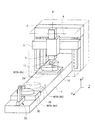
本実施例に係る三次元レーザ加工機は、図1に示すように、床面に水平に設置されるベッド1と、ベッド1を跨ぐように設置される門形のコラム2と、コラム2の前面に支持されコラム2に対してZ軸方向(垂直方向)に移動可能なクロスレール3と、クロスレール3に支持されクロスレール3に沿ってY軸方向(水平方向)に移動可能なサドル4と、サドル4に把持されサドル4に対してZ軸方向に移動可能なラム5とを有する。
As shown in FIG. 1, the three-dimensional laser processing machine according to this embodiment includes a
ラム5には、ラム5に対してZ軸方向に移動可能かつC軸方向(Z軸と平行な軸回り)に回動可能なレーザヘッド10を設け、レーザヘッド10には、レーザヘッド10に対してB軸方向(Y軸と平行な軸回り)に回動可能なレーザ光照射部11を備える。
The
レーザ光照射部11から照射されるレーザ光は、レーザヘッド10に内蔵された図示しない集光レンズによって、被加工物であるワークWにおける図示しない被加工部または被加工部の近傍で集光する。ワークWの図示しない被加工部が、集光したレーザ光を照射されることによって熱せられ、局所的に溶融すると共に、被加工部の溶融した部材がレーザヘッド10に備える図示しないガス噴射部から噴射されるガスによって吹き飛ばされることにより、ワークWの切断や穴明けの高精度な加工が行われる。
The laser beam emitted from the laser
なお、三次元レーザ加工機においては、作業員の安全性を確保する等のために安全カバー6を備え、レーザ加工を行う範囲を区分けしている。図1においては、図を明瞭にするために、安全カバー6を二点鎖線で示している。
In the three-dimensional laser processing machine, a
ベッド1には、ワークWを加工するための加工用テーブル20と、ワークWを段取りするための段取りプレート30と、ワーク入替え装置40(図3乃至図6参照)とを備える。図1においては、ワーク入替え装置40の図示を省略している。
The
加工用テーブル20は、加工位置(図1における実線部)と段取り位置(図1における二点鎖線部)との間を移動可能にベッド1上に設置され、段取りプレート30は、段取り位置における加工用テーブル20と隣り合うようにベッド1の一端側に設置され(図1参照)、ワーク入替え装置40は、段取り位置における加工用テーブル20と段取りプレート30との間に設置される(図3乃至図6参照)。
The processing table 20 is installed on the
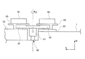
ワーク入替え装置40は、図3乃至図6に示すように、本体部41とワーク把持部42とを有し、更に、本体部41およびワーク把持部42をW軸方向(Z軸に平行な軸方向)に昇降させる図示しない昇降機構と、本体部41およびワーク把持部42をD軸方向(W軸に平行な軸回り)に回転させる図示しない回転機構とを備える。
As shown in FIGS. 3 to 6, the
ワーク入替え装置40によって、レーザ加工を終えて段取り位置へ移動してきた加工用テーブル20上における加工後のワークW1と、レーザ加工を施すために新たに三次元レーザ加工機に搬入された段取りプレート30上における加工前のワークW2との入替え作業を行うことができる。ワーク入替え装置40による加工後のワークW1と加工前のワークW2との入替え作業については後述する。
The workpiece W 1 after processing on the processing table 20 that has been moved to the setup position after the laser processing by the
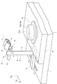
本実施例においては、図1に示すように、三次元レーザ加工機におけるベッド1に、加工前および加工後におけるワークWの三次元形状を測定するための三次元形状測定器であるスキャニング装置50を備える。スキャニング装置50は、ベッド1の一端側におけるワークWの段取りスペースに設置され、図2に示すように、ベッド1に対してV軸方向(Y軸に平行な軸方向)に摺動可能な土台部51と、土台部51に支持され土台部51に対してU軸方向(X軸に平行な軸方向)に摺動可能な胴部52と、胴部52に支持され胴部52に対してW軸方向に摺動可能な腕部53と、腕部53の一端側に支持されU軸方向に摺動可能かつE軸方向(V軸に平行な軸回り)に回動可能な首部54とを備える。
In this embodiment, as shown in FIG. 1, a
首部54には、ワークWの三次元形状を測定するための二つのカメラ55を有する。なお、段取りプレート30には、スキャニング装置50によって加工前および加工後におけるワークW全体の形状を測定することができるように、段取りプレート30上に設置されたワークWをF軸方向(Z軸およびW軸に平行な軸回り)に回転させることができる図示しない回転機構を設けている。
The
つまり、スキャニング装置50における土台部51のV軸方向への摺動、胴部52のU軸方向への摺動、腕部53のW軸方向への摺動、首部54のU軸方向への摺動かつE軸方向への回動、および段取りプレート30上におけるワークWのF軸方向への回転動作によって、種々の大きさおよび形状におけるワークWの三次元形状の測定を行うことができる。
That is, sliding of the
なお、三次元レーザ加工機におけるワークWの搬入および搬出は、段取りプレート30において行われる。また、ワークWは、ワーク設置治具60を介して段取りプレート30上へ設置され、ワーク設置治具60と共に段取りプレート30上で回転され、ワーク設置治具60と共にワーク入替え装置40による入替えがなされる(図3乃至図6参照)。
The work W is carried in and out in the three-dimensional laser processing machine on the
次に、本発明の実施例1に係る三次元レーザ加工機によるレーザ加工の流れについて、図1乃至図6を参照して説明する。
Next, the flow of laser processing by the three-dimensional laser processing machine according to
まず、加工位置の加工用テーブル20上においてワークW1にレーザ加工を施している間に、図示しないクレーンまたは作業員の手作業によって、加工前のワークW2を三次元レーザ加工機における段取りプレート30上にワーク設置治具60を介して設置し、スキャニング装置50による加工前のワークW2の三次元形状測定を行う(図1および図2参照)。
First, while the workpiece W 1 is being subjected to laser processing on the processing table 20 at the processing position, the workpiece W 2 before being processed is manually set up by a crane (not shown) or a worker by a setup plate in a three-dimensional laser processing machine. The workpiece W 2 is placed on the
段取りプレート30の近傍に設置されたスキャニング装置50の土台部51、胴部52、腕部53、および首部54を摺動または回動させることにより、カメラ55の撮影位置および撮影方向を調整し、スキャニング装置50を段取りプレート30上に設置された加工前のワークW2の三次元形状測定に適するようにする。
Adjust the shooting position and shooting direction of the
段取りプレート30上において、図示しない回転機構によってワーク設置治具60と加工前のワークW2をF軸方向に回転させると共に、スキャニング装置50によって加工前のワークW2の三次元形状測定を行う。スキャニング装置50によって測定された加工前のワークW2の三次元形状データd2は、図示しないデータ処理部に伝達され、後述する加工前のワークW2のレーザ加工に供される。
On the
なお、本実施例のように、加工前のワークW2の三次元レーザ加工機への搬入およびスキャニング装置50による三次元形状測定を、三次元レーザ加工機へ搬入済みのワークW1にレーザ加工を施している間に行うことにより、ワークW1に対するレーザ加工とワークW2に対する三次元形状測定とが並行して行われるので、三次元レーザ加工機におけるレーザ加工の加工効率を向上させることができる。
As in this embodiment, the workpiece W 2 before processing is carried into the three-dimensional laser beam machine and the three-dimensional shape measurement by the
次に、ワーク入替え装置40によって、加工後のワークW1と加工前のワークW2との入替え作業を行う(図1、図3乃至図6参照)。
Next, the
加工用テーブル20上に設置された加工後のワークW1が、加工位置においてレーザ加工された後、段取り位置へ移動する(図1参照)。 The processed workpiece W 1 placed on the processing table 20 is laser processed at the processing position and then moved to the setup position (see FIG. 1).
そして、図3に示すように、ワーク入替え装置40における一方(図3における右方側)の把持部42は、段取り位置へ移動してきた加工用テーブル20上で加工後のワークW1が固定されたワーク設置治具60を把持し、他方(図3における左方側)の把持部42は、段取りプレート30上で加工前のワークW2が固定されたワーク設置治具60を把持する。
As shown in FIG. 3, the gripping
続いて、図4に示すように、ワーク入替え装置40における図示しない昇降機構によって、本体部41がW軸方向に上昇すると共に、把持部42、把持部42に把持されたワーク設置治具60、およびワーク設置治具60上に固定された加工後のワークW1ならびに加工前のワークW2が上昇する。
Subsequently, as shown in FIG. 4, the
続いて、図5に示すように、ワーク入替え装置40における図示しない回転機構によって、本体部41がD軸方向に回転すると共に、把持部42、把持部42に把持されたワーク設置治具60、およびワーク設置治具60に固定された加工後のワークW1ならびに加工前のワークW2が回転する。よって、加工後のワークW1は段取りプレート30の上方に位置し、加工前のワークW2は加工用テーブル20の上方に位置することになる。
Subsequently, as shown in FIG. 5, the
続いて、図6に示すように、ワーク入替え装置40における図示しない昇降機構によって、本体部41がW軸方向に下降すると共に、把持部42、把持部42に把持されたワーク設置治具60、およびワーク設置治具60上に固定された加工後のワークW1ならびに加工前のワークW2が下降する。
Subsequently, as shown in FIG. 6, the
図示しない昇降機構によって本体部41がW軸方向に下降することで、ワーク設置治具60およびワーク設置治具60上に固定された加工後のワークW1は段取りプレート30上に設置され、ワーク設置治具60およびワーク設置治具60上に固定された加工前のワークW2は加工用テーブル20上に設置され、加工後のワークW1と加工前のワークW2との入替え作業が完了する。
The
次に、スキャニング装置50による加工後のワークW1の三次元形状測定を行い、加工前のワークW2にレーザ加工を施す(図1および図2参照)。
Next, the three-dimensional shape measurement of the workpiece W 1 after processing is performed by the
前述した加工前のワークW2の三次元形状測定と同様に、カメラ55の撮影位置および撮影方向を調整し、スキャニング装置50によって段取りプレート30上に設置された加工後のワークW1の三次元形状測定を行う(図2参照)。スキャニング装置50によって測定された加工後のワークW1の三次元形状データd1は、図示しないデータ処理部に伝達され、加工前のワークW2の三次元形状データd2と共に、後述する加工前のワークW2のレーザ加工に供される。
Similar to the above-described three-dimensional shape measurement of the workpiece W 2 before processing, the shooting position and shooting direction of the
なお、本実施例における三次元レーザ加工機では、ワークWに穴明けの加工のみを施しているので、加工後のワークW1と加工前のワークW2の形状に大きな変化がない。よって、カメラ55の撮影位置および撮影方向の調整を省略する。もちろん、三次元レーザ加工機においてワークWに切断等のレーザ加工を施し、加工前のワークW2の形状と加工後のワークW1の形状とに大きな形状変化がある場合等には、再度カメラ55の撮影位置および撮影方向の調整を行っても良い。
In the three-dimensional laser processing machine according to the present embodiment, since only the drilling process is performed on the workpiece W, there is no significant change in the shape of the workpiece W 1 after processing and the workpiece W 2 before processing. Therefore, adjustment of the shooting position and shooting direction of the
スキャニング装置50による三次元形状測定を終えた加工後のワークW1は、図示しないクレーンまたは作業員の手作業によって段取りプレート30上から取り除かれ、新たなワークW3(図示せず)が図示しないクレーンまたは作業員の手作業によって、段取りプレート30上にワーク設置治具60を介して設置される。
The processed workpiece W 1 after finishing the three-dimensional shape measurement by the
一方、加工用テーブル20上に設置されたワーク設置治具60および加工前のワークW2は、加工用テーブル20が段取り位置から加工位置へ移動することにより、加工位置に位置する(図1参照)。加工用テーブル20上にワーク設置治具60を介して設置された加工前のワークW2は、加工位置において、レーザ加工を施される。
On the other hand, the
このとき加工前のワークW2のレーザ加工に使用される加工用データD2は、前述した加工前のワークW2の三次元形状データd2と、加工後のワークW1の三次元形状データd1とを織り込んだものである。 At this time, the processing data D 2 used for laser processing of the workpiece W 2 before processing includes the three-dimensional shape data d 2 of the workpiece W 2 before processing and the three-dimensional shape data of the workpiece W 1 after processing. d 1 is incorporated.
具体的には、加工前のワークW2の三次元形状データd2に基づいて、ワークW毎に異なる僅かな形状の差異やワーク設置治具60に対するワークW2の位置を反映し、ワークW2の図示しない被加工部をレーザ加工するためのレーザ光照射部11の位置およびレーザ光の照射方向を修正する。これにより、照射されたレーザ光の焦点位置とワークW2の被加工部との距離を正確に把握して、所定の距離となるように設定することが可能となる。
Specifically, based on the three-dimensional shape data d 2 of the workpiece W 2 before processing, a slight difference in shape that differs for each workpiece W and the position of the workpiece W 2 relative to the
また、前述した加工後のワークW1の三次元形状データd1と、ワークW1に施されたレーザ加工の加工用データD1とを比較し、ワークW1が加工用データD1通りにレーザ加工を施されているか否か、すなわち、三次元レーザ加工機におけるレーザ加工の加工精度を確認する。これにより、レーザ加工の際に生じる加工誤差等を検知することができ、その加工誤差等のデータをワークW2の加工データD2に織り込むことで、ワークW2に加工誤差等を補正したレーザ加工を施すことができる。 Further, a three-dimensional shape data d 1 of the work W 1 after processing as described above, compares the processed data D 1 of the laser processing applied to the work W 1, the workpiece W 1 is the ways for processing data D 1 Whether or not laser processing is performed, that is, the processing accuracy of laser processing in a three-dimensional laser processing machine is confirmed. Thus, it is possible to detect the machining error or the like occurring during the laser processing, the interworking data such as the processing error in the processed data D 2 of the workpiece W 2, the laser obtained by correcting the machining error or the like on the workpiece W 2 Processing can be performed.
よって、従来の三次元レーザ加工機のように、ギャップセンサ等を用いて被加工部とレーザ光照射部との距離を被加工部毎に測定する必要がなく、ギャップセンサによるギャップ検出時間を削減することができる。よって、三次元レーザ加工機におけるレーザ加工の加工効率を向上させることができる。 Therefore, unlike the conventional 3D laser processing machine, it is not necessary to measure the distance between the processing part and the laser beam irradiation part for each processing part using a gap sensor or the like, and the gap detection time by the gap sensor is reduced. can do. Therefore, the processing efficiency of laser processing in the three-dimensional laser processing machine can be improved.
もちろん、本発明におけるワークW1の三次元形状測定とワークW2のレーザ加工のタイミング、および加工後のワークW1の三次元形状データd1を加工用データに織り込むタイミングについては、本実施例に限定されない。例えば、ワークW2にレーザ加工を施している間に、加工後のワークW1の三次元形状を測定し、その次のワークW3(図示せず)の加工用データD3に、加工後のワークW1の三次元形状データd1を織り込んでも良い。 Of course, the timing of the three-dimensional shape measurement of the workpiece W 1 and the laser processing of the workpiece W 2 and the timing of weaving the three-dimensional shape data d 1 of the workpiece W 1 after processing into the processing data in the present embodiment will be described in the present embodiment. It is not limited to. For example, while laser processing is performed on the workpiece W 2 , the three-dimensional shape of the workpiece W 1 after processing is measured, and the processing data D 3 of the next workpiece W 3 (not shown) is added to the processing data D 3 after processing. The three-dimensional shape data d 1 of the workpiece W 1 may be incorporated.
また、本実施例では、ワークWの段取りおよび三次元形状測定を加工用テーブル20とは別の段取りプレート30において行い、ワークWを加工用テーブルおよび段取りプレート30上にワーク設置治具60を介して設置したが、本発明はこれに限定されない。例えば、段取り位置における加工用テーブル20上に直接ワークWを段取りし、段取り位置における加工用テーブル20の近傍にスキャニング装置50を設け、加工用テーブル20上に直接設置された状態でワークWの加工前および加工後の三次元形状測定を行っても良い。
In the present embodiment, the work W is set up and the three-dimensional shape is measured on the set-
また、本実施例では、三次元形状測定器としてスキャニング装置50を用いたが、本発明はこれに限定されない。例えば、三次元形状測定器として、非接触式(ポイントレーザ、ラインレーザ、光学式)、接触式(プローブ)を用いても良い。
In the present embodiment, the
なお、本発明は、レーザ加工における「切断」、「穴明け」、「溶接」、「クラッディング」、「表面改質」、「面粗度向上」にも適用することができる。 The present invention can also be applied to “cutting”, “drilling”, “welding”, “cladding”, “surface modification”, and “surface roughness improvement” in laser processing.
1 ベッド
2 コラム
3 クロスレール
4 サドル
5 ラム
6 安全カバー
10 レーザヘッド
11 レーザ光照射部
20 加工用テーブル
30 段取りプレート
40 ワーク入替え装置
41 ワーク入替え装置の本体部
42 ワーク入替え装置の把持部
50 スキャニング装置
51 スキャニング装置の土台部
52 スキャニング装置の胴部
53 スキャニング装置の腕部
54 スキャニング装置の首部
55 スキャニング装置のカメラ
60 ワーク設置治具
DESCRIPTION OF
Claims (3)
前記被加工物の三次元形状を測定する三次元形状測定器を備え、
前記三次元形状測定器によって測定した前記被加工物の三次元形状データに基づいて、レーザ加工における前記レーザ光の焦点位置を、前記被加工部と所定の距離に設定する
ことを特徴とする三次元レーザ加工機。 This is a three-dimensional laser processing machine that performs high-precision laser processing on the workpiece by setting the focal position of the laser beam focused by the condenser lens to a predetermined distance from the workpiece on the workpiece. And
Comprising a three-dimensional shape measuring instrument for measuring the three-dimensional shape of the workpiece;
Based on the three-dimensional shape data of the workpiece measured by the three-dimensional shape measuring instrument, the focal position of the laser beam in laser processing is set to a predetermined distance from the workpiece. Former laser processing machine.
前記被加工物にレーザ加工を施す前に、前記三次元形状測定器によって前記段取りスペースに段取りした前記被加工物の三次元形状を測定する
ことを特徴とする請求項1に記載の三次元レーザ加工機。 Installing the three-dimensional shape measuring instrument in the setup space of the workpiece;
2. The three-dimensional laser according to claim 1, wherein the three-dimensional shape of the workpiece set in the set-up space is measured by the three-dimensional shape measuring instrument before performing laser processing on the workpiece. Processing machine.
レーザ加工後における前記被加工物の三次元形状データによってレーザ加工の加工精度を確認する
ことを特徴とする請求項1または請求項2に記載の三次元レーザ加工機。 After performing laser processing on the workpiece, measure the three-dimensional shape of the workpiece by the three-dimensional shape measuring instrument,
The three-dimensional laser processing machine according to claim 1 or 2, wherein the processing accuracy of laser processing is confirmed by three-dimensional shape data of the workpiece after laser processing.
Priority Applications (8)
| Application Number | Priority Date | Filing Date | Title |
|---|---|---|---|
| JP2013002328A JP2014133248A (en) | 2013-01-10 | 2013-01-10 | Three dimensional laser beam machine |
| US14/759,848 US20150336209A1 (en) | 2013-01-10 | 2013-11-08 | Three-dimensional laser processing machine |
| EP13870900.1A EP2944414A4 (en) | 2013-01-10 | 2013-11-08 | Three-dimensional laser processing machine |
| CA2897472A CA2897472A1 (en) | 2013-01-10 | 2013-11-08 | Three-dimensional laser processing machine |
| KR1020157018465A KR20150092320A (en) | 2013-01-10 | 2013-11-08 | Three-dimensional laser processing machine |
| CN201380070104.3A CN104918744B (en) | 2013-01-10 | 2013-11-08 | Three-dimensional beam machine |
| PCT/JP2013/080208 WO2014109120A1 (en) | 2013-01-10 | 2013-11-08 | Three-dimensional laser processing machine |
| TW102143321A TWI583480B (en) | 2013-01-10 | 2013-11-27 | Three - dimensional laser processing machine |
Applications Claiming Priority (1)
| Application Number | Priority Date | Filing Date | Title |
|---|---|---|---|
| JP2013002328A JP2014133248A (en) | 2013-01-10 | 2013-01-10 | Three dimensional laser beam machine |
Publications (2)
| Publication Number | Publication Date |
|---|---|
| JP2014133248A true JP2014133248A (en) | 2014-07-24 |
| JP2014133248A5 JP2014133248A5 (en) | 2016-02-25 |
Family
ID=51166785
Family Applications (1)
| Application Number | Title | Priority Date | Filing Date |
|---|---|---|---|
| JP2013002328A Pending JP2014133248A (en) | 2013-01-10 | 2013-01-10 | Three dimensional laser beam machine |
Country Status (8)
| Country | Link |
|---|---|
| US (1) | US20150336209A1 (en) |
| EP (1) | EP2944414A4 (en) |
| JP (1) | JP2014133248A (en) |
| KR (1) | KR20150092320A (en) |
| CN (1) | CN104918744B (en) |
| CA (1) | CA2897472A1 (en) |
| TW (1) | TWI583480B (en) |
| WO (1) | WO2014109120A1 (en) |
Cited By (4)
| Publication number | Priority date | Publication date | Assignee | Title |
|---|---|---|---|---|
| JP2020011251A (en) * | 2018-07-17 | 2020-01-23 | 株式会社デンソー | Laser processing device |
| WO2020031948A1 (en) * | 2018-08-06 | 2020-02-13 | 国立大学法人東京大学 | Machine learning method used for laser processing system, simulation device, laser processing system, and program |
| WO2020066440A1 (en) * | 2018-09-26 | 2020-04-02 | 日本電産マシナリー株式会社 | Liquid application device |
| JP2022036306A (en) * | 2017-05-01 | 2022-03-04 | 株式会社ニコン | Processing device and processing method |
Families Citing this family (10)
| Publication number | Priority date | Publication date | Assignee | Title |
|---|---|---|---|---|
| GB2536434A (en) * | 2015-03-16 | 2016-09-21 | Sony Corp | A cutting device, cutting equipment and method |
| US20160311062A1 (en) * | 2015-04-21 | 2016-10-27 | Rohr, Inc. | Machining a freely arranged or partially constrained composite part using a laser system |
| CN105215545A (en) * | 2015-11-11 | 2016-01-06 | 苏州天弘激光股份有限公司 | Wafer straight cutting machine |
| KR101811696B1 (en) * | 2016-01-25 | 2017-12-27 | 주식회사 쓰리디시스템즈코리아 | 3D scanning Apparatus and 3D scanning method |
| USD850500S1 (en) * | 2016-08-31 | 2019-06-04 | Trumpf Gmbh + Co. Kg | Machine tool |
| TWI677393B (en) * | 2017-05-10 | 2019-11-21 | 崔秉燦 | Jig assembly for laser processing apparatus,and method and apparatus comprising the same |
| KR102186303B1 (en) * | 2018-10-11 | 2020-12-04 | 주식회사 인스텍 | Real-Time Automatic Height Tracer Control System Using Image Processing and Method Thereof |
| CN110147073A (en) * | 2019-06-21 | 2019-08-20 | 东莞市力星激光科技有限公司 | A kind of control system of laser pipe cutter |
| CN112077450A (en) * | 2020-08-17 | 2020-12-15 | 黑龙江职业学院(黑龙江省经济管理干部学院) | High-efficient laser engraving module |
| IT202100030350A1 (en) * | 2021-11-30 | 2023-05-30 | Luca Zanotto | APPARATUS AND PROCEDURE FOR THE SURFACE PROCESSING OF SHEET-SHAPED ELEMENTS |
Citations (4)
| Publication number | Priority date | Publication date | Assignee | Title |
|---|---|---|---|---|
| JPH10156677A (en) * | 1996-12-04 | 1998-06-16 | Amada Washino Co Ltd | Grinding method and grinding machine |
| JP2006098065A (en) * | 2004-09-28 | 2006-04-13 | Sanyo Electric Co Ltd | Calibration device and method, and three-dimensional modelling device and system capable of using the same |
| JP2008043973A (en) * | 2006-08-14 | 2008-02-28 | Nissan Motor Co Ltd | Laser beam machining apparatus and laser beam machining method therefor |
| JP2012192503A (en) * | 2011-03-17 | 2012-10-11 | Panasonic Electric Works Co Ltd | Ultraprecision composite processing device and ultraprecision composite processing method |
Family Cites Families (14)
| Publication number | Priority date | Publication date | Assignee | Title |
|---|---|---|---|---|
| JPS6127192A (en) | 1984-07-17 | 1986-02-06 | Mitsubishi Heavy Ind Ltd | Laser working machine |
| CA2251243C (en) * | 1998-10-21 | 2006-12-19 | Robert Dworkowski | Distance tracking control system for single pass topographical mapping |
| JP3806342B2 (en) * | 2001-11-26 | 2006-08-09 | 三菱重工業株式会社 | Three-dimensional object welding method and apparatus |
| EP1585613A1 (en) * | 2002-09-13 | 2005-10-19 | Tamicare Ltd. | Laser modification of complex objects |
| JP3796207B2 (en) * | 2002-09-20 | 2006-07-12 | 新潟県 | Machining method by 3D laser processing machine and NC program creation method for 3D laser processing |
| JP2005021937A (en) * | 2003-07-01 | 2005-01-27 | Sumitomo Heavy Ind Ltd | Laser beam machining device and laser beam machining method |
| US7638731B2 (en) * | 2005-10-18 | 2009-12-29 | Electro Scientific Industries, Inc. | Real time target topography tracking during laser processing |
| CN101138926A (en) * | 2007-02-28 | 2008-03-12 | 浙江省林业科学研究院 | Profile modeling laser engraving process method and laser carving machine thereof |
| JP2009082932A (en) * | 2007-09-28 | 2009-04-23 | Pulstec Industrial Co Ltd | Laser beam machining apparatus and laser beam machining method |
| JP2010017745A (en) | 2008-07-11 | 2010-01-28 | Mitsui Seiki Kogyo Co Ltd | 5-axis laser processing system |
| CN101372070B (en) * | 2008-08-15 | 2011-06-22 | 东莞华中科技大学制造工程研究院 | Linkage rod type laser welding and measurement integrated device |
| CN101376194B (en) * | 2008-08-19 | 2011-02-16 | 东莞华中科技大学制造工程研究院 | On-line measurement compensating mechanism for laser beam welding |
| JP5318544B2 (en) * | 2008-12-01 | 2013-10-16 | 株式会社ディスコ | Laser processing equipment |
| CN101786200B (en) * | 2010-02-26 | 2012-01-25 | 华中科技大学 | Method for projection-type laser etching on free curved surface |
-
2013
- 2013-01-10 JP JP2013002328A patent/JP2014133248A/en active Pending
- 2013-11-08 US US14/759,848 patent/US20150336209A1/en not_active Abandoned
- 2013-11-08 CN CN201380070104.3A patent/CN104918744B/en not_active Expired - Fee Related
- 2013-11-08 CA CA2897472A patent/CA2897472A1/en not_active Abandoned
- 2013-11-08 EP EP13870900.1A patent/EP2944414A4/en not_active Withdrawn
- 2013-11-08 KR KR1020157018465A patent/KR20150092320A/en not_active Application Discontinuation
- 2013-11-08 WO PCT/JP2013/080208 patent/WO2014109120A1/en active Application Filing
- 2013-11-27 TW TW102143321A patent/TWI583480B/en not_active IP Right Cessation
Patent Citations (4)
| Publication number | Priority date | Publication date | Assignee | Title |
|---|---|---|---|---|
| JPH10156677A (en) * | 1996-12-04 | 1998-06-16 | Amada Washino Co Ltd | Grinding method and grinding machine |
| JP2006098065A (en) * | 2004-09-28 | 2006-04-13 | Sanyo Electric Co Ltd | Calibration device and method, and three-dimensional modelling device and system capable of using the same |
| JP2008043973A (en) * | 2006-08-14 | 2008-02-28 | Nissan Motor Co Ltd | Laser beam machining apparatus and laser beam machining method therefor |
| JP2012192503A (en) * | 2011-03-17 | 2012-10-11 | Panasonic Electric Works Co Ltd | Ultraprecision composite processing device and ultraprecision composite processing method |
Cited By (9)
| Publication number | Priority date | Publication date | Assignee | Title |
|---|---|---|---|---|
| JP2022036306A (en) * | 2017-05-01 | 2022-03-04 | 株式会社ニコン | Processing device and processing method |
| JP2022105133A (en) * | 2017-05-01 | 2022-07-12 | 株式会社ニコン | Processing device and processing method |
| US11691217B2 (en) | 2017-05-01 | 2023-07-04 | Nikon Corporation | Laser processing device with optical device for changing cross-sectional intensity distribution of a beam at a pupil plane |
| JP7347554B2 (en) | 2017-05-01 | 2023-09-20 | 株式会社ニコン | Processing equipment and processing method |
| JP2020011251A (en) * | 2018-07-17 | 2020-01-23 | 株式会社デンソー | Laser processing device |
| JP7056425B2 (en) | 2018-07-17 | 2022-04-19 | 株式会社デンソー | Laser processing equipment |
| WO2020031948A1 (en) * | 2018-08-06 | 2020-02-13 | 国立大学法人東京大学 | Machine learning method used for laser processing system, simulation device, laser processing system, and program |
| JPWO2020031948A1 (en) * | 2018-08-06 | 2021-08-10 | 国立大学法人 東京大学 | Machine learning methods, simulation equipment, laser machining systems and programs used in laser machining systems |
| WO2020066440A1 (en) * | 2018-09-26 | 2020-04-02 | 日本電産マシナリー株式会社 | Liquid application device |
Also Published As
| Publication number | Publication date |
|---|---|
| US20150336209A1 (en) | 2015-11-26 |
| WO2014109120A1 (en) | 2014-07-17 |
| CN104918744B (en) | 2016-11-23 |
| CA2897472A1 (en) | 2014-07-17 |
| TWI583480B (en) | 2017-05-21 |
| CN104918744A (en) | 2015-09-16 |
| EP2944414A4 (en) | 2016-02-17 |
| KR20150092320A (en) | 2015-08-12 |
| TW201429598A (en) | 2014-08-01 |
| EP2944414A1 (en) | 2015-11-18 |
Similar Documents
| Publication | Publication Date | Title |
|---|---|---|
| WO2014109120A1 (en) | Three-dimensional laser processing machine | |
| JP6037891B2 (en) | Tool shape measuring method and tool shape measuring device | |
| US10474123B2 (en) | Method and apparatus for detecting and correcting a spatial position of a workpiece held in a positioning device | |
| KR101527311B1 (en) | Machine tool | |
| US20180290234A1 (en) | Composite printing device featuring multi-spindle high-energy-particle-beam deposition welding and milling | |
| JP2016093872A (en) | Device and method of automatically setting tool correction value of machine tool | |
| JP5642819B2 (en) | Wire electric discharge machine having taper angle correction function using contact detector and taper angle correction method | |
| KR101492339B1 (en) | Method for controlling laser cladding and laser cladding system | |
| KR101673062B1 (en) | Method for measuring height of melt pool generated in laser cladding | |
| JP2014013547A (en) | Error correction device and method in machining system | |
| CN210387968U (en) | Laser cutting equipment | |
| CN117340634B (en) | Machine tool for precision machining of parts and control system thereof | |
| JP2017124485A (en) | Machine tool and correction method of tool tip position | |
| KR102002297B1 (en) | Method for creating work path of work piece using laser cladding system | |
| KR20150053884A (en) | Method for creating work path of work piece using laser cladding system | |
| JP6397776B2 (en) | Calibration jig, calibration method, and laser processing machine | |
| Gessner et al. | Accuracy of the new method of alignment of workpiece using structural-light 3D scanner | |
| JP4242229B2 (en) | Method and apparatus for correcting thermal displacement of machine tool | |
| CN116160120B (en) | Machining method and machining system for improving abrasion resistance of tenon tooth mortises of turbine blades | |
| JP2006021277A (en) | Tool centering method and tool measuring method | |
| CN215698850U (en) | Laser cutting head height calibration device | |
| JP2005028432A (en) | Plate dimension measuring method in plate working machine, work clamp position determining method, and work clamp device used for the method | |
| JPH10337637A (en) | Working method for reference hole and working device for reference hole | |
| JP2024059274A (en) | Processing device | |
| Jezeršek et al. | Real time surface deformations monitoring during laser processing |
Legal Events
| Date | Code | Title | Description |
|---|---|---|---|
| A521 | Request for written amendment filed |
Free format text: JAPANESE INTERMEDIATE CODE: A523 Effective date: 20160108 |
|
| A621 | Written request for application examination |
Free format text: JAPANESE INTERMEDIATE CODE: A621 Effective date: 20160108 |
|
| A711 | Notification of change in applicant |
Free format text: JAPANESE INTERMEDIATE CODE: A712 Effective date: 20160309 |
|
| A131 | Notification of reasons for refusal |
Free format text: JAPANESE INTERMEDIATE CODE: A131 Effective date: 20160906 |
|
| A521 | Request for written amendment filed |
Free format text: JAPANESE INTERMEDIATE CODE: A523 Effective date: 20161107 |
|
| A131 | Notification of reasons for refusal |
Free format text: JAPANESE INTERMEDIATE CODE: A131 Effective date: 20161206 |
|
| A02 | Decision of refusal |
Free format text: JAPANESE INTERMEDIATE CODE: A02 Effective date: 20170606 |