JP2014124902A - Blow molding plastic bottle and manufacturing method of blow molding plastic bottle - Google Patents
Blow molding plastic bottle and manufacturing method of blow molding plastic bottle Download PDFInfo
- Publication number
- JP2014124902A JP2014124902A JP2012284995A JP2012284995A JP2014124902A JP 2014124902 A JP2014124902 A JP 2014124902A JP 2012284995 A JP2012284995 A JP 2012284995A JP 2012284995 A JP2012284995 A JP 2012284995A JP 2014124902 A JP2014124902 A JP 2014124902A
- Authority
- JP
- Japan
- Prior art keywords
- plastic bottle
- surface member
- bottle
- blow
- main body
- Prior art date
- Legal status (The legal status is an assumption and is not a legal conclusion. Google has not performed a legal analysis and makes no representation as to the accuracy of the status listed.)
- Granted
Links
Images


Abstract
Description
本発明は、主として飲食品等の内容液を収容するブロー成形プラスチックボトルおよびブロー成形プラスチックボトルの製造方法に関する。 The present invention mainly relates to a blow-molded plastic bottle that contains content liquids such as food and drink, and a method for producing a blow-molded plastic bottle.
近時、飲食品等の内容液を収容するボトルとして、プラスチック製のものが一般化してきており、このようなプラスチックボトルには内容液が収容される。 Recently, plastic bottles for storing content liquids such as foods and drinks have become common, and such plastic bottles store content liquids.
このような内容液を収容するプラスチックボトルは、金型内にプリフォームを挿入し、ブロー成形することにより製造される。 A plastic bottle that contains such a content liquid is manufactured by inserting a preform into a mold and blow-molding it.
ところで、プラスチックボトル内には飲食品等の内容液が収納されるが、内容液が高温のとき、プラスチックボトルを把持することがむずかしい場合がある。他方、内容液が低温の場合、プラスチックボトルに結露が生じ見栄えが悪くなる。 By the way, although content liquids, such as food and drink, are accommodated in a plastic bottle, when a content liquid is high temperature, it may be difficult to hold | grip a plastic bottle. On the other hand, when the content liquid is at a low temperature, dew condensation occurs on the plastic bottle and the appearance is poor.
本発明はこのような点を考慮してなされたものであり、内容液が高温の場合であっても容易に把持することができ、内容液が低温の場合であっても結露して見栄えが悪くなりにくい、ブロー成形プラスチックボトルおよびブロー成形プラスチックボトルの製造方法を提供することを目的とする。 The present invention has been made in consideration of the above points, and can be easily gripped even when the content liquid is high temperature, and even if the content liquid is low temperature, condensation forms and looks good. An object of the present invention is to provide a blow-molded plastic bottle and a method for producing a blow-molded plastic bottle that are unlikely to deteriorate.
本発明は、ブロー成形プラスチックボトルにおいて、予め金型内に挿着された表面部材と、金型内の表面部材内側に挿入されたプリフォームをブロー成形して得られ、口部と、肩部と、胴部と、底部とを有するボトル本体とを備え、表面部材はボトル本体の外面に設けられ、表面部材とボトル本体との間に中間部材が介在されていることを特徴とするブロー成形プラスチックボトルである。 The present invention is a blow molded plastic bottle obtained by blow molding a surface member inserted in a mold in advance and a preform inserted inside the surface member in the mold, a mouth portion, a shoulder portion And a bottle body having a body portion and a bottom portion, a surface member is provided on an outer surface of the bottle body, and an intermediate member is interposed between the surface member and the bottle body. It is a plastic bottle.
本発明は、中間部材はシュリンクラベルからなり、ボトル本体を収縮させて、表面部材とボトル本体との間に空間を形成することを特徴とするブロー成形プラスチックボトルである。 The present invention is the blow-molded plastic bottle, wherein the intermediate member is formed of a shrink label, and the bottle body is contracted to form a space between the surface member and the bottle body.
本発明は、表面部材はボトル本体の肩部、胴部または底部の外面に設けられていることを特徴とするブロー成形プラスチックボトルである。 The present invention is the blow molded plastic bottle characterized in that the surface member is provided on the outer surface of the shoulder portion, the trunk portion or the bottom portion of the bottle body.
本発明は、ボトル本体および表面部材の胴部に、水平方向に溝が形成されていることを特徴とするブロー成形プラスチックボトルである。 The present invention is a blow-molded plastic bottle characterized in that a groove is formed in the horizontal direction in the bottle body and the body part of the surface member.
本発明は、ブロー成形プラスチックボトルの製造方法において、金型内に表面部材を挿着するとともに、金型内の表面部材内側に中間部材を挿着する工程と、金型内の中間部材の内側にプリフォームを挿入し、このプリフォームをブロー成形することにより、口部と、肩部と、胴部と、底部とを有するボトル本体を成形する工程とを備え、表面部材とボトル本体との間に中間部材が介在されることを特徴とするブロー成形プラスチックボトルの製造方法である。 The present invention relates to a method of manufacturing a blow molded plastic bottle, the step of inserting a surface member into a mold, and inserting an intermediate member inside the surface member in the mold, and the inside of the intermediate member in the mold And forming a bottle body having a mouth portion, a shoulder portion, a trunk portion, and a bottom portion by inserting the preform into the preform and blow-molding the preform. An intermediate member is interposed between the blow molded plastic bottles.
本発明は、中間部材はシュリンクラベルからなり、ボトル本体を収縮させて、表面部材とボトル本体との間に空間を形成することを特徴とするブロー成形プラスチックボトルの製造方法である。 The present invention is the blow molded plastic bottle manufacturing method, wherein the intermediate member is formed of a shrink label, and the bottle body is contracted to form a space between the surface member and the bottle body.
本発明は、表面部材はボトル本体の肩部、胴部または底部の外面に設けられていることを特徴とするブロー成形プラスチックボトルの製造方法である。 The present invention is the method for producing a blow-molded plastic bottle characterized in that the surface member is provided on the outer surface of the shoulder, body or bottom of the bottle body.
本発明は、ボトル本体および表面部材の胴部に、水平方向に溝が形成されていることを特徴とするブロー成形プラスチックボトルの製造方法である。 The present invention is a method for producing a blow-molded plastic bottle, characterized in that a groove is formed in the horizontal direction in the body of the bottle body and the surface member.
本発明によれば、ブロー成形プラスチックボトルは、表面部材と、表面部材の内側に設けられプリフォームをブロー成形してなるボトル本体とを備え、表面部材はボトル本体の外面に設けられている。さらにまた、表面部材とボトル本体との間に中間部材が介在されている。このため内容液が高温であっても表面部材に直接熱が伝わることはなく、表面部材を容易に把持することができる。また内容液が低温であっても、表面部材あるいはボトル本体表面に結露が発生しにくい。 According to the present invention, a blow-molded plastic bottle includes a surface member and a bottle main body formed by blow-molding a preform provided inside the surface member, and the surface member is provided on the outer surface of the bottle main body. Furthermore, an intermediate member is interposed between the surface member and the bottle body. For this reason, even if the content liquid is high temperature, heat is not directly transmitted to the surface member, and the surface member can be easily gripped. Even when the content liquid is at a low temperature, condensation is unlikely to occur on the surface member or the bottle body surface.
実施の形態
以下、図面を参照して本発明の一実施の形態について説明する。図1乃至図5は本発明の一実施の形態を示す図である。
Embodiment Hereinafter, with reference to the drawings illustrating an embodiment of the present invention. 1 to 5 are views showing an embodiment of the present invention.
まず、図1乃至図3により、本実施の形態によるブロー成形プラスチックボトルの概要について説明する。なお、本明細書中、「上」および「下」とは、それぞれプラスチックボトル10を正立させた状態(図1)における上方および下方のことをいう。
First, an outline of a blow molded plastic bottle according to the present embodiment will be described with reference to FIGS. In the present specification, “upper” and “lower” refer to the upper side and the lower side in a state where the
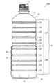
図1乃至図3に示すブロー成形プラスチックボトル10Aは、後述する金型50内に予め挿着された表面部材40と、表面部材40内側に挿入されたプリフォーム10aをブロー成形して得られたプラスチックボトル本体(ボトル本体)10と、表面部材40とボトル本体10との間に介在された中間部材41とを備えている。このうち、ボトル本体10は、上述のように射出成形により得られるプリフォーム10aを準備し、このプリフォーム10aに対して金型50内で二軸延伸ブロー成形を施すことにより作製される(図4(a)〜(e))。このようなプラスチックボトル本体10は、例えば450ml〜650mlの容積をもつボトルからなっている。
The blow-molded
プラスチックボトル本体10は、口部11と、口部11下方に設けられた肩部12と、肩部12下方に設けられた胴部20と、胴部20下方に設けられた底部30とを備えている。
The
他方、表面部材40は、プラスチックボトル本体10を準備し、このプラスチックボトル本体10の胴部20の中央部で水平方向に切断することにより得られる。また表面部材40はプラスチックボトル本体10外面に接着されることなく、接触した状態で取付けられている。また中間部材41は、表面部材40内面に予め取付られている。
On the other hand, the
次にプラスチックボトル本体10について詳述する。プラスチックボトル本体10の胴部20は、全体として円筒形状を有しており、その上下方向中央部に位置する中央水平方向溝21を介して上半部20Aと下半部20Bとに区画されている。これら上半部20Aと下半部20Bとには、それぞれ複数の水平方向溝22〜24が形成されている。
Next, the
また、複数の水平方向溝22〜24は、少なくとも2種類の深さの水平方向溝を含んでいる。具体的には、水平方向溝22〜24は、最大の深さをもつ第1水平方向溝22と、中間の深さをもつ第2水平方向溝23と、最小の深さをもつ第3水平方向溝24とを含んでいる。なお、中央水平方向溝21の深さは、第1水平方向溝22の深さと同一である。
The plurality of
これら水平方向溝21〜24は、それぞれ胴部20の円周方向全周に延びており、その上下方向の幅は、それぞれ円周方向全周にわたって均一である。
These
一方、胴部20のうち、水平方向溝21〜24が形成されていない領域は、円筒面25からなっている。すなわち、各水平方向溝21〜24同士の間には、円筒面25が形成されている。このように、胴部20は、各水平方向溝21〜24および円筒面25のみから構成されている。
On the other hand, a region of the
この水平方向溝21〜24が形成されていない領域(円筒面25)は、肩部12の直下から底部30の直上まで均一の径を有している。これにより、プラスチックボトル本体10を自動販売機内で横向きに収納した際、隣接する他のプラスチックボトル本体10に対して広い面積で接触させることができるので、自動販売機内で胴部20が変形することを防止することができる。
The region (cylindrical surface 25) where the
一方、図2に示すように、底部30は、中央に位置する円形状の凹部31と、この凹部31から放射状に延びる放射状リブ32とを有している。なお、図2において、放射状リブ32の本数は7本であるが、これに限らず、例えば5本〜11本の範囲で設定しても良い。このように放射状リブ32を配置したことにより、底部30の強度を高め、底部30に変形が生じにくいようになっている。
On the other hand, as shown in FIG. 2, the
また胴部20の円筒面25におけるプラスチックボトル本体10の厚みは、これに限定されるものではないが、例えば50μm〜250μm程度に薄くすることができる。さらに、プラスチックボトル本体10の重量についても、これに限定されるものではないが、10g〜20gとすることができる。このようにプラスチックボトル本体10の肉厚を薄くすることにより、プラスチックボトル10の軽量化を図ることができる。
Moreover, although the thickness of the plastic bottle
このようなプラスチックボトル本体10は、合成樹脂材料を射出成形して製作したプリフォーム10aを二軸延伸ブロー成形することにより作製することができる。なおプリフォーム10a、すなわちプラスチックボトル本体10の材料としては熱可塑性樹脂、特にPE(ポリエチレン)、PP(ポリプロピレン)、PET(ポリエチレンテレフタレート)、PEN(ポリエチレンナフタレート)を使用する事が好ましい。
Such a plastic bottle
また、プラスチックボトル本体10は、2層以上の多層成形ボトルとして形成することもできる。すなわち押し出し成形または射出成形により、例えば、中間層をMXD6、MXD6+脂肪酸塩、PGA(ポリグリコール酸)、EVOH(エチレンビニルアルコール共重合体)又はPEN(ポリエチレンナフタレート)等のガスバリア性及び遮光性を有する樹脂(中間層)として3層以上からなるプリフォーム10aを押出成形後、ブロー成形することによりガスバリア性及び遮光性を有する多層ボトルとして形成しても良い。なお、このような中間層は、プラスチックボトル本体10のうち少なくとも胴部20内に設けることが好ましい。また底部30において、底部30の中央部を除く領域に中間層を設けることが好ましい。ケース落下等の衝撃を受けた際この部分がデラミ(層間剥離)を起こすおそれがあるからである。ガスバリア性及び遮光性を有する為に、多層にするだけでなく熱可塑性樹脂同士をブレンドしたブレンドボトルを形成しても良い。
Moreover, the plastic bottle
次に表面部材40について説明する。表面部材40は上述のようにプリフォーム10aをブロー成形することにより得られるプラスチックボトル本体10を準備し、このプラスチックボトル本体10の胴部20の中央部を水平方向に切断することにより得られるため、表面部材40は略円筒状の胴部と底部とを有する。
Next, the
表面部材40はプラスチックボトル本体10の外面に接着されることなく取付けられ、さらに表面部材40とプラスチックボトル本体10との間に円筒状のシュリンクラベルからなる中間部材41が介在され、この中間部材41によって表面部材40とプラスチックボトル本体10との間に空間45が形成されている(図3参照)。このため内容液が高温であっても表面部材40に直接熱が伝わることはなく、表面部材を容易に把持することができる。また内容液が低温であっても、表面部材あるいはボトル本体表面に結露が発生しにくい。
The
なお、表面部材40はプラスチックボトル本体10の胴部20および底部30に対応しているが、プラスチックボトル本体10の胴部20に対応してもよく、底部30に対応してもよく、肩部12に対応して形成されていてもよい。
The
次に表面部材40とプラスチックボトル本体10との間に介在された円筒状のシュリンクラベルからなる中間部分41について説明する。図1乃至図4(a)〜(e)に示すように、円筒状のシュリンクラベルからなる中間部材41は、プラスチックボトル本体10の外面を内側に押圧させて収縮させる。このことにより中間部材41により収縮されたプラスチックボトル本体10と、中間部材41との間に、比較的大きな空間45が形成されている(図3参照)。
Next, the
次に表面部材40および中間部材41について更に説明する。表面部材40は上述のようにプリフォーム10aをブロー成形することにより得られるプラスチックボトル本体10を準備し、このプラスチックボトル本体10の胴部20の中央部を水平方向に切断することにより得られるため、表面部材40は略円筒状の胴部と底部とを有する。
Next, the
また中間部材41はシュリンクラベルからなり、加熱されて収縮して、プラスチックボトル本体10を押圧する。
Further, the
表面部材40はプラスチックボトル本体10の外面に接着されることなく取付けられ、表面部材40と中間部材41により収縮されたプラスチックボトル本体10との間に空間45が形成されている。
The
この場合、プラスチックボトル本体10は中間部材41により収縮されるため、表面部材40とプラスチックボトル本体10との間に、比較的大きな空間45を確実に形成することができる(図3参照)。
In this case, since the plastic bottle
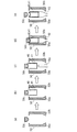
次に図4(a)〜(e)により、ブロー成形プラスチックボトル10Aの製造方法について説明する。
Next, a method for manufacturing the blow molded
ブロー成形プラスチックボトル10Aは、ブロー成形金型50を用いて成形される。この場合、ブロー成形金型50は互いに分割された一対の胴部金型50a、50bと、底部金型50cとからなる(図4(a)参照)。
The blow molded
次に図4(b)に示すように、底部金型50cに表面部材40が吸着され、底部金型50cに吸着された表面部材40が、一対の胴部金型50a、50b間に挿着される。この場合、表面部材40内面にシュリンクラベルからなる中間部材41が貼り付けられている。図4(b)において、一対の胴部金型50a、50b間は互いに開いている。
Next, as shown in FIG. 4B, the
この状態で一対の胴部金型50a、50b間に、プリフォーム10aが下方から挿入される(図4(c)参照)。
In this state, the
次に図4(d)に示すように、一対の胴部金型50a、50bが閉鎖され、一対の胴部金型50a、50bおよび底部金型50cにより密閉されたブロー成形金型50が構成される。次にプリフォーム10a内に空気が圧入され、プリフォーム10aに対してブロー成形が施される。
Next, as shown in FIG. 4 (d), the pair of
このことによりブロー成形金型50内でプリフォーム10aからプラスチックボトル本体10が得られる。この間、ブロー成形金型50は所定温度まで加熱される。
As a result, the
ブロー成形金型50内では、プラスチックボトル本体10の外面が表面部材40の内面へ押付けられる。この場合、表面部材40はプラスチックボトル本体10の外面に接着することなく、接触した状態で取付けられる。
In the
そして表面部材40の内側に位置する中間部材41が加熱されて収縮し、中間部材41によりプラスチックボトル本体10も収縮する。このことにより表面部材40とプラスチックボトル本体10との間に比較的大きな空間45が形成される(図3参照)。
And the
このようにして、プラスチックボトル本体10と、プラスチックボトル本体10の外面に設けられた表面部材40と、表面部材40とプラスチックボトル本体10との間に介在された中間部材41とを備えたブロー成形プラスチックボトル10Aが得られる。
Thus, the blow molding provided with the plastic bottle
次に図4(e)に示すように、一対の胴部金型50a、50bおよび底部金型50cが互いに離れ、ブロー成形金型50内からブロー成形プラスチックボトル10Aが取出される。
Next, as shown in FIG. 4 (e), the pair of
実施例
(試験A)
次に本発明の具体的実施例について説明する。まず本発明によるプラスチックボトル本体10と、表面部材40と、ボトル主体10と表面部材40との間に介在された中間部材41とを有するブロー成形プラスチックボトル(二重ボトル)10Aを準備するとともに(図1参照)、表面部材のない比較例としてのプラスチックボトル本体(一重ボトル)を準備した。
Example (Test A)
Next, specific examples of the present invention will be described. First, a blow molded plastic bottle (double bottle) 10A having a plastic bottle
次に本発明によるブロー成形プラスチックボトルと、比較例としてのプラスチックボトル本体の双方に、ボトル空寸法が20mlとなるよう25℃の水を充てんし、5℃の環境下で24時間冷却した。 Next, both the blow-molded plastic bottle according to the present invention and the plastic bottle body as a comparative example were filled with water at 25 ° C. so that the bottle empty dimension was 20 ml, and cooled in an environment at 5 ° C. for 24 hours.
冷却された本発明による二重ボトルと比較例としての一重ボトルを25℃40%RH環境下におき、放置した後に結露を確認した。 The cooled double bottle according to the present invention and a single bottle as a comparative example were placed in an environment of 25 ° C. and 40% RH and left to stand to confirm dew condensation.
その結果、本発明によるブロー成形プラスチックボトル(二重ボトル)では、表面部材40の表面、および表面部材40の内側に位置するプラスチックボトル本体10の部分(プラスチックボトル本体10の下方部分)の表面の双方に結露は生じにくく、表面部材40およびその内側のプラスチックボトル本体10の部分を通して、外方から内容液を確認することができた。
As a result, in the blow-molded plastic bottle (double bottle) according to the present invention, the surface of the
すなわち、本発明によるブロー成形プラスチックボトル10Aにおいて、表面部材40とプラスチックボトル本体10との間に空間45が形成されているため、プラスチックボトル本体10表面と内容液との間の温度差を小さいが、表面部材40とプラスチックボトル本体10の間隙から水分の流入が殆どないため、プラスチックボトル本体10の表面に結露が生じにくい。また空間45により表面部材40の表面とプラスチックボトル本体10の表面との間の温度差を大きくすることができ、このため表面部材40の表面に結露が生じにくい。
That is, in the blow molded
他方、比較例によるプラスチックボトル本体(一重ボトル)では、その表面全域に結露が生じ内容液を確認することはできなかった。 On the other hand, in the plastic bottle body (single bottle) according to the comparative example, dew condensation occurred on the entire surface, and the content liquid could not be confirmed.
(試験B)
本発明による二重ボトルおよび比較例としての一重ボトルの双方に、ボトル空寸量が20mlとなるように25℃の水を充てんし、−20℃の環境下で24時間冷却を行った。
(Test B)
Both the double bottle according to the present invention and the single bottle as a comparative example were filled with 25 ° C. water so that the bottle empty size was 20 ml, and cooled in an environment of −20 ° C. for 24 hours.
冷却された二重ボトルおよび一重ボトルの双方を20℃環境下に晒し、経時的に表面温度をサーモグラフィで計測した。また、中が完全に氷解する経過時間を計測した。結果を表1および図5に示す。

表1および図5に示すように本発明によるブロー成形プラスチックボトル(二重ボトル)のうち、表面部材40の表面、すなわち二重部分の表面では、その表面温度は最初から大きく低下することはなく、略一定となっている。これは表面部材40とプラスチックボトル本体10との間に空気層43が形成され、この空気層43が断熱効果を発揮するからである。
As shown in Table 1 and FIG. 5, among the blow molded plastic bottles (double bottles) according to the present invention, the surface temperature of the
また本発明によるブロー成形プラスチックボトル(二重ボトル)のうち表面部材40がない上方部分表面、すなわち一重部分の表面では、その表面温度は最初大きく低下し(−20℃近傍)、時間の経過とともに室温近くまで上昇している。
In addition, the surface temperature of the blow molded plastic bottle (double bottle) according to the present invention on the upper part surface where the
他方、比較例としてのプラスチックボトル本体(一重ボトル)では、二重ボトルの一重部分と同一の挙動、すなわちその表面温度は最初大きく低下し(−20℃近傍)、時間の経過とともに室温近くまで上昇している。 On the other hand, in the plastic bottle body (single bottle) as a comparative example, the same behavior as that of the single part of the double bottle, that is, its surface temperature is greatly reduced at first (near -20 ° C), and rises to near room temperature as time passes. doing.
本発明の変形例
次に図6および図7(a)〜(e)により本発明の変形例について説明する。
Modified Example of the Invention Next, a modified example of the present invention will be described with reference to FIGS. 6 and 7A to 7E.
図6および図7(a)〜(e)に示す変形例は、表面部材40として胴部と底部とを有するものではなく、円筒状の表面部材40を用いたものである。この表面部材40は図6に示すように、プラスチックボトル本体10の胴部20のうち中央部分から下方部分まで延びているが、底部30まで達していない。図6および図7(a)〜(e)において他の構成は、図1乃至図5に示す実施の形態と略同一である。
The modification shown in FIGS. 6 and 7A to 7E does not have a body portion and a bottom portion as the
図6および図7(a)〜(e)に示す変形例において、図1乃至図5に示す実施の形態と同一部分には同一符号を付して詳細な説明は省略する。 In the modification shown in FIGS. 6 and 7A to 7E, the same parts as those in the embodiment shown in FIGS.
次に表面部材40について説明する。表面部材40はプリフォーム10aをブロー成形することにより得られるプラスチックボトル本体10を準備し、このプラスチックボトル本体10の胴部を2箇所、水平方向に切断することにより得られるため、表面部材40は略円筒状の胴部を有する。また表面部材40とプラスチックボトル本体10との間に円筒状のシュリンクラベルからなる中間部材41が介在され、中間部材41は加熱されて収縮してプラスチックボトル本体10を押圧する。
Next, the
表面部材40はプラスチックボトル本体10の外面に接着されることなく取付けられ、表面部材40と中間部材41により収縮されたプラスチックボトル本体10との間に空間45が形成されている。
The
次に図7(a)〜(e)により、ブロー成形プラスチックボトル10Aの製造方法について説明する。
Next, a manufacturing method of the blow molded
ブロー成形プラスチックボトル10Aは、ブロー形成金型50を用いて成形される。この場合、ブロー成形金型50は互いに分割された一対の胴部金型50a、50bと、底部金型50cとからなる(図7(a)参照)。
The blow molded
次に図7(b)に示すように、一方の胴部金型50a内面に表面部材40が吸着される。この場合、表面部材40内面にシュリンクラベルからなる中間部材41が貼り付けられている。図7(b)において、一対の胴部金型50a、50b間は互いに開いている。
Next, as shown in FIG. 7B, the
この状態で一対の胴部金型50a、50b間に、プリフォーム10aが下方から挿入される(図7(c)参照)。
In this state, the
次に図7(d)に示すように、一対の胴部金型50a、50bが閉鎖され、一対の胴部金型50a、50bおよび底部金型50cにより密閉されたブロー成形金型50が構成される。次にプリフォーム10a内に空気が圧入され、プリフォーム10aに対してブロー成形が施される。
Next, as shown in FIG. 7 (d), a pair of
このことによりブロー成形金型50内でプリフォーム10aからプラスチックボトル本体10が得られる。この間、ブロー成形金型50は所定温度まで加熱される。
As a result, the
ブロー成形金型50内では、プラスチックボトル本体10の外面が表面部材40の内面へ押付けられる。この場合、表面部材40はプラスチックボトル本体10の外面に接着することなく、接触した状態で取付けられる。
In the
そして表面部材40の内側に位置する中間部材41が加熱されて収縮し、中間部材41によりプラスチックボトル本体10も収縮する。このことにより表面部材40とプラスチックボトル本体10との間に比較的大きな空間45が形成される(図3参照)。
And the
このようにして、プラスチックボトル本体10と、プラスチックボトル本体10の外面に設けられた表面部材40と、表面部材40とプラスチックボトル本体10との間に介在された中間部材41とを備えたブロー成形プラスチックボトル10Aが得られる。
Thus, the blow molding provided with the plastic bottle
なお、上記実施の形態において、表面部材40がブロー成形により得られたプラスチックボトル本体10の胴部20中央部を水平方向に切断することにより得られる例を示したが、これに限らずプラスチックボトル本体10の胴部20を斜め方向に、あるいは曲面上に切断することにより表面部材40を形成してもよい。
In the above-described embodiment, the example in which the
あるいは表面部材40をプラスチック以外の材料、例えば木材や金属から形成してもよい。また表面部材をブロー成形以外の方法、例えば射出成形、インフレーション法または押し成形により形成してもよい。
Alternatively, the
10 プラスチックボトル
10A プラスチックボトル本体
10a プリフォーム
11 口部
12 肩部
20 胴部
20A 上半部
20B 下半部
30 底部
40 表面部材
41 中間部材
43 空気層
45 空間
50 ブロー成形金型
50a、50b 胴部金型
50c 底部金型
DESCRIPTION OF
Claims (8)
予め金型内に挿着された表面部材と、
金型内の表面部材内側に挿入されたプリフォームをブロー成形して得られ、口部と、肩部と、胴部と、底部とを有するボトル本体とを備え、
表面部材はボトル本体の外面に設けられ、表面部材とボトル本体との間に中間部材が介在されていることを特徴とするブロー成形プラスチックボトル。 In blow molded plastic bottles,
A surface member inserted in the mold in advance;
It is obtained by blow molding a preform inserted inside the surface member in the mold, and includes a bottle body having a mouth portion, a shoulder portion, a trunk portion, and a bottom portion,
A blow molded plastic bottle, wherein the surface member is provided on an outer surface of the bottle body, and an intermediate member is interposed between the surface member and the bottle body.
金型内に表面部材を挿着するとともに、金型内の表面部材内側に中間部材を挿着する工程と、
金型内の中間部材の内側にプリフォームを挿入し、このプリフォームをブロー成形することにより、口部と、肩部と、胴部と、底部とを有するボトル本体を成形する工程とを備え、
表面部材とボトル本体との間に中間部材が介在されることを特徴とするブロー成形プラスチックボトルの製造方法。 In the method of manufacturing a blow molded plastic bottle,
Inserting a surface member into the mold and inserting an intermediate member inside the surface member in the mold; and
A step of forming a bottle body having a mouth portion, a shoulder portion, a body portion, and a bottom portion by inserting a preform inside the intermediate member in the mold and blow-molding the preform. ,
An intermediate member is interposed between the surface member and the bottle main body.
Priority Applications (1)
| Application Number | Priority Date | Filing Date | Title |
|---|---|---|---|
| JP2012284995A JP6070178B2 (en) | 2012-12-27 | 2012-12-27 | Blow molded plastic bottle and method for producing blow molded plastic bottle |
Applications Claiming Priority (1)
| Application Number | Priority Date | Filing Date | Title |
|---|---|---|---|
| JP2012284995A JP6070178B2 (en) | 2012-12-27 | 2012-12-27 | Blow molded plastic bottle and method for producing blow molded plastic bottle |
Related Child Applications (1)
| Application Number | Title | Priority Date | Filing Date |
|---|---|---|---|
| JP2017000521A Division JP6274329B2 (en) | 2017-01-05 | 2017-01-05 | Blow molded plastic bottle and method for producing blow molded plastic bottle |
Publications (2)
| Publication Number | Publication Date |
|---|---|
| JP2014124902A true JP2014124902A (en) | 2014-07-07 |
| JP6070178B2 JP6070178B2 (en) | 2017-02-01 |
Family
ID=51404809
Family Applications (1)
| Application Number | Title | Priority Date | Filing Date |
|---|---|---|---|
| JP2012284995A Active JP6070178B2 (en) | 2012-12-27 | 2012-12-27 | Blow molded plastic bottle and method for producing blow molded plastic bottle |
Country Status (1)
| Country | Link |
|---|---|
| JP (1) | JP6070178B2 (en) |
Cited By (3)
| Publication number | Priority date | Publication date | Assignee | Title |
|---|---|---|---|---|
| JP2016107602A (en) * | 2014-12-10 | 2016-06-20 | 大日本印刷株式会社 | Manufacturing apparatus and manufacturing method of composite container, manufacturing apparatus and manufacturing method of composite preform, composite container and composite preform |
| CN106604872A (en) * | 2014-07-31 | 2017-04-26 | 帝斯克玛股份有限公司 | Composite container |
| JP7094913B2 (en) | 2019-04-25 | 2022-07-04 | 大日本印刷株式会社 | Composite container and its manufacturing method |
Citations (4)
| Publication number | Priority date | Publication date | Assignee | Title |
|---|---|---|---|---|
| JPS60167708U (en) * | 1984-04-13 | 1985-11-07 | 高圧化工株式会社 | multilayer container |
| JPH1045164A (en) * | 1996-08-02 | 1998-02-17 | Toppan Printing Co Ltd | Easily degradable composite container |
| JP2005047538A (en) * | 2003-07-28 | 2005-02-24 | Yoshino Kogyosho Co Ltd | Manufacturing method of double container made of synthetic resin, and double container made of synthetic resin |
| JP2012096831A (en) * | 2010-11-02 | 2012-05-24 | Dainippon Printing Co Ltd | Composite container and method for manufacturing same |
-
2012
- 2012-12-27 JP JP2012284995A patent/JP6070178B2/en active Active
Patent Citations (4)
| Publication number | Priority date | Publication date | Assignee | Title |
|---|---|---|---|---|
| JPS60167708U (en) * | 1984-04-13 | 1985-11-07 | 高圧化工株式会社 | multilayer container |
| JPH1045164A (en) * | 1996-08-02 | 1998-02-17 | Toppan Printing Co Ltd | Easily degradable composite container |
| JP2005047538A (en) * | 2003-07-28 | 2005-02-24 | Yoshino Kogyosho Co Ltd | Manufacturing method of double container made of synthetic resin, and double container made of synthetic resin |
| JP2012096831A (en) * | 2010-11-02 | 2012-05-24 | Dainippon Printing Co Ltd | Composite container and method for manufacturing same |
Cited By (3)
| Publication number | Priority date | Publication date | Assignee | Title |
|---|---|---|---|---|
| CN106604872A (en) * | 2014-07-31 | 2017-04-26 | 帝斯克玛股份有限公司 | Composite container |
| JP2016107602A (en) * | 2014-12-10 | 2016-06-20 | 大日本印刷株式会社 | Manufacturing apparatus and manufacturing method of composite container, manufacturing apparatus and manufacturing method of composite preform, composite container and composite preform |
| JP7094913B2 (en) | 2019-04-25 | 2022-07-04 | 大日本印刷株式会社 | Composite container and its manufacturing method |
Also Published As
| Publication number | Publication date |
|---|---|
| JP6070178B2 (en) | 2017-02-01 |
Similar Documents
| Publication | Publication Date | Title |
|---|---|---|
| JP2015009493A (en) | Blow molding method and composite preform | |
| JP6044871B2 (en) | Blow molded plastic bottle and method for producing blow molded plastic bottle | |
| JP2013023227A (en) | Heat labile molded plastic bottle | |
| JP6070178B2 (en) | Blow molded plastic bottle and method for producing blow molded plastic bottle | |
| JP6363009B2 (en) | Plastic bottle | |
| JP2014151932A (en) | Plastic bottle | |
| JP5893401B2 (en) | Plastic bottle | |
| JP2014061936A (en) | Plastic bottle | |
| JP6185234B2 (en) | Cup-type container and molding method thereof | |
| JP6274329B2 (en) | Blow molded plastic bottle and method for producing blow molded plastic bottle | |
| JP6299848B2 (en) | Blow molded plastic bottle and method for producing blow molded plastic bottle | |
| JP7015474B2 (en) | Plastic bottle | |
| JP6160896B2 (en) | Plastic bottle | |
| JP7059563B2 (en) | Preform manufacturing method | |
| JP2012116160A (en) | Preform | |
| JP5556083B2 (en) | Plastic bottle | |
| JP2017148963A (en) | Manufacturing method of blow molding plastic bottle, blow molding plastic bottle, blow molding plastic bottle die and surface member | |
| JP2019042995A (en) | Laminated preform, container, manufacturing method of laminated preform, and manufacturing method of container | |
| JP6443712B2 (en) | Blow molded plastic bottle | |
| JP5446553B2 (en) | Plastic bottle for heating | |
| JP5446554B2 (en) | Plastic bottle for heating | |
| JP2013184723A (en) | Plastic bottle | |
| JP6363010B2 (en) | Plastic bottle | |
| JP6968740B2 (en) | Manufacturing method of composite container | |
| JP2015199521A (en) | Blow molding plastic bottle |
Legal Events
| Date | Code | Title | Description |
|---|---|---|---|
| A621 | Written request for application examination |
Free format text: JAPANESE INTERMEDIATE CODE: A621 Effective date: 20151029 |
|
| A977 | Report on retrieval |
Free format text: JAPANESE INTERMEDIATE CODE: A971007 Effective date: 20160830 |
|
| A131 | Notification of reasons for refusal |
Free format text: JAPANESE INTERMEDIATE CODE: A131 Effective date: 20160902 |
|
| A521 | Written amendment |
Free format text: JAPANESE INTERMEDIATE CODE: A523 Effective date: 20161014 |
|
| TRDD | Decision of grant or rejection written | ||
| A01 | Written decision to grant a patent or to grant a registration (utility model) |
Free format text: JAPANESE INTERMEDIATE CODE: A01 Effective date: 20161206 |
|
| A61 | First payment of annual fees (during grant procedure) |
Free format text: JAPANESE INTERMEDIATE CODE: A61 Effective date: 20161219 |
|
| R150 | Certificate of patent or registration of utility model |
Ref document number: 6070178 Country of ref document: JP Free format text: JAPANESE INTERMEDIATE CODE: R150 |
|
| RD02 | Notification of acceptance of power of attorney |
Free format text: JAPANESE INTERMEDIATE CODE: R3D02 |