JP2014121663A - Resonance device, vibratory device and bell rumbling device - Google Patents
Resonance device, vibratory device and bell rumbling device Download PDFInfo
- Publication number
- JP2014121663A JP2014121663A JP2012278066A JP2012278066A JP2014121663A JP 2014121663 A JP2014121663 A JP 2014121663A JP 2012278066 A JP2012278066 A JP 2012278066A JP 2012278066 A JP2012278066 A JP 2012278066A JP 2014121663 A JP2014121663 A JP 2014121663A
- Authority
- JP
- Japan
- Prior art keywords
- iron core
- movable iron
- solenoid
- vibration
- ring magnet
- Prior art date
- Legal status (The legal status is an assumption and is not a legal conclusion. Google has not performed a legal analysis and makes no representation as to the accuracy of the status listed.)
- Granted
Links
Images
Landscapes
- Apparatuses For Generation Of Mechanical Vibrations (AREA)
- Reciprocating, Oscillating Or Vibrating Motors (AREA)
Abstract
Description
本発明は、共振装置、これを使用した振動装置、および、この振動装置を利用したベル鳴動装置に関する。 The present invention relates to a resonance device, a vibration device using the resonance device, and a bell ringing device using the vibration device.
ある質量を持った可動子を振動させる装置は、携帯電話の呼び出し装置、ベルの打棒駆動装置、篩い装置など広い用途を持つ。 A device for vibrating a mover having a certain mass has a wide range of applications such as a mobile phone calling device, a bell hitting rod drive device, and a sieving device.
従来、この種の装置は偏心モータ、モータの回転をクランクで直線運動に変えるもの、振動部をその質量とバネの弾力とで共振装置とし電磁石の磁力で駆動して振動させるもの(特許文献1参照)等がある。 Conventionally, this type of device is an eccentric motor, a device that changes the rotation of the motor to a linear motion with a crank, and a vibrating portion that is driven by the magnetic force of an electromagnet using a mass and the elasticity of a spring to vibrate (Patent Document 1) See).
しかし、モータとクランクを使用するものは摩擦が大きく振動の振幅を変化することが困難であるなどの欠点があり、また、バネと質量による共振を使用するものは、効率はよいがバネが折れやすいという問題を有していたりする。 However, those using a motor and a crank have drawbacks such as large friction and difficult to change the amplitude of vibration, and those using a resonance with a spring and mass are efficient but the spring breaks. There is a problem that it is easy.
一例として、従来の、振動部を質量とバネの弾力とで共振装置を構成させると共に電磁石の磁力で振動を附勢する振動装置について説明すると、上記振動装置は、図7の平面図および図8の縦断面図に示すように、ケース52の中途高さ位置にコイル46を固定して設け、このコイル46を内部に収容する状態で振動部42をケース52内に横方向移動自在に配置するともに、ケース52と振動部42との間にバネ44を介装したものである。振動部42は、コイル46を挟む上下のマグネット80、82と、可動ヨーク66、68と、ウェイト90、92とを一体化したものである。
As an example, a description will be given of a conventional vibration device in which a vibration device is configured by a mass and the elasticity of a spring and energizes vibration by the magnetic force of an electromagnet. The vibration device includes a plan view of FIG. As shown in the longitudinal sectional view, the
上記振動装置において、コイル46に正負の電流を流すことで、マグネット80、82を含む振動部42の質量がバネ44の弾性力と共振して振動し、この振動の反動でケース52およびその周りの固定部材が振動する。振動部42は、その質量とバネ44とが共振して振動するが、その振動は、コイル46に共振周波数の電流を与えることで、持続させるようになっている。
In the above-described vibration device, when positive and negative currents are passed through the
しかしながら、上記の振動装置では、振動部42の質量とバネ44からなる共振装置を利用するので、電気/機械のエネルギー変換効率がよいが、バネ44を使用しているので、頻繁に動作させるものでは、バネの疲労や破損が生じやすくて寿命が短い。
However, since the above-described vibration device uses a resonance device composed of the mass of the
本発明は、バネを使用せず故障が少なくて長年月使用できる共振装置、振動装置およびベル鳴動装置を提供することを課題とする。 An object of the present invention is to provide a resonance device, a vibration device, and a bell ringing device that can be used for many months without using a spring.
本発明の発明者が、リング磁石と、その中に置かれたリング磁石の軸方向に動きうる棒状の可動鉄心とに着目してその動作作用を検討したところ、リング磁石が可動鉄心に与える磁気吸引力は可動鉄心の変位に比例し、機械的な共振機構でのバネの復元力と同じ特性を持っており、リング磁石と可動鉄心とが共振装置を構成していることが判明した。 The inventor of the present invention examined the operation of the ring magnet and the rod-shaped movable iron core that can move in the axial direction of the ring magnet placed in the ring magnet. The attractive force is proportional to the displacement of the movable iron core and has the same characteristics as the restoring force of the spring in the mechanical resonance mechanism, and it has been found that the ring magnet and the movable iron core constitute a resonance device.
本発明に係る共振装置は、上記判明した事実に基づいて為されたもので、軸方向に貫通した貫通穴を有するリング磁石と、前記貫通穴内を軸方向移動可能に配置された可動鉄心とを備え、前記リング磁石の軸方向の中心位置と前記可動鉄心の軸方向の静止位置とを一致ないしほぼ一致させ、前記リング磁石の磁気吸引力と前記可動鉄心の質量とで軸方向において共振装置とすることを特徴とする。 The resonance device according to the present invention is made on the basis of the above-described fact, and includes a ring magnet having a through hole penetrating in the axial direction, and a movable iron core arranged to be movable in the axial direction in the through hole. A center position in the axial direction of the ring magnet and an axial stationary position of the movable iron core are matched or substantially matched, and a resonance device in the axial direction is formed by the magnetic attraction force of the ring magnet and the mass of the movable core. It is characterized by doing.
また、本発明に係る振動装置は、前記共振装置と、前記共振装置のリング磁石と軸を共通にして軸方向に並置されたソレノイドとを備え、前記共振装置の可動鉄心の振動周期のうち特定の期間、前記ソレノイドを励磁して、前記可動鉄心の振動を附勢することを特徴とするものである。この場合、可動鉄心は、リング磁石の内部に軸方向に移動可能であり、ソレノイドを、リング磁石の可動鉄心移動方向一方側もしくは両側に、上記可動鉄心の振動附勢用として並置したことを特徴とする。 In addition, the vibration device according to the present invention includes the resonance device and a solenoid arranged in parallel in the axial direction with the ring magnet of the resonance device and a shaft in common, and the vibration device of the movable iron core of the resonance device is identified. During this period, the solenoid is excited to oscillate the vibration of the movable iron core. In this case, the movable iron core is movable in the axial direction inside the ring magnet, and the solenoid is juxtaposed on one side or both sides of the ring magnet in the movable iron core moving direction for urging the movable iron core. And
上記振動装置においては、共振装置内の可動鉄心に初動を与えると、この可動鉄心の質量と可動鉄心に作用するリング磁石の磁気吸引力との間で共振周波数の過渡振動が生じる。振動により可動鉄心が一方側に移動している期間、その側の振動附勢用のソレノイドが通電により励磁され磁気吸引力を生じることで、可動鉄心の振動が維持される。 In the above vibration device, when an initial motion is applied to the movable iron core in the resonance device, transient vibration of a resonance frequency is generated between the mass of the movable iron core and the magnetic attractive force of the ring magnet acting on the movable iron core. During the period in which the movable iron core is moved to one side by vibration, the vibration urging solenoid on that side is excited by energization to generate a magnetic attractive force, thereby maintaining the vibration of the movable iron core.
本発明の共振装置によれば、共振用バネの代わりにリング磁石の磁気吸引力を利用するので、バネを使わずに済み、バネの疲労、破損等による機械的な故障がなく長年月使用できる。 According to the resonance device of the present invention, since the magnetic attractive force of the ring magnet is used instead of the resonance spring, it is not necessary to use a spring, and it can be used for many years without mechanical failure due to fatigue or damage of the spring. .
つぎに、本発明の振動装置によれば、前記共振装置に振動附勢用としてソレノイドを並置しており,共振を利用するので電気/機械エネルギー変換効率が高い。また、ソレノイドに流す電流の位相と大きさによって可動鉄心の振幅を調節できる。この場合、第1のソレノイドと逆方向に振動を附勢する第2の振動附勢用ソレノイドを設置し、励磁することによってさらに強く振動を附勢することができる。 Next, according to the vibration device of the present invention, a solenoid is juxtaposed to the resonance device for energizing vibration, and since resonance is used, the electrical / mechanical energy conversion efficiency is high. Moreover, the amplitude of the movable iron core can be adjusted by the phase and magnitude of the current flowing through the solenoid. In this case, the vibration can be further strongly urged by installing and exciting a second vibration urging solenoid that urges the vibration in the opposite direction to the first solenoid.
さらに、本発明のベル鳴動装置によれば、前記振動装置の可動鉄心を打棒として半サイクルごとに附勢して、その可動鉄心を強力に振動させてベルを連打すれば、強いベル音を発生させることができる。 Further, according to the bell ringing device of the present invention, if the movable iron core of the vibration device is energized every half cycle as the hitting rod, and the bell is continuously hit by vigorously vibrating the movable iron core, a strong bell sound is generated. Can be made.
添付した図面を参照して、本発明の各実施形態を説明する。なお、各図中、同一ないし対応する部分には同一の符号を付している。 Embodiments of the present invention will be described with reference to the accompanying drawings. In addition, in each figure, the same code | symbol is attached | subjected to the same thru | or corresponding part.
〔第1の実施形態〕
図1(a)は、本発明の第1の実施形態を示すものである。
[First Embodiment]
Fig.1 (a) shows the 1st Embodiment of this invention.
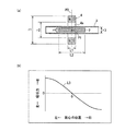
2は、可動鉄心であって、軸方向に所定長で延びた円柱形状をなしている。
3は、断面円形の中空のパイプであって、非磁性体材料からなり、かつ、軸方向直線的に延在して配置されている。パイプ3内には前記可動鉄心2が軸方向において自由に移動可能に配置されている。
4は、リング磁石であり、フェライトやネオジム等の永久磁石材料からなりかつ中央が軸方向に円形に貫通した貫通穴4aを有したリング状になって、貫通穴4aの貫通方向である軸方向においてNSに着磁されている。このリング磁石4の貫通穴4aに、パイプ3が軸方向に沿って挿通されている。
4 is a ring magnet, which is made of a permanent magnet material such as ferrite or neodymium and has a ring shape with a through
なお、リング磁石4の外径をr1、内径をr2、パイプ3内の直径をr3、可動鉄心2の直径をr4とし、また、リング磁石4の軸方向長さをL1、可動鉄心2の軸方向長さをL2とすると、r1>r2>r3>r4であり、L1<L2である。
The outer diameter of the
特に、リング磁石4の貫通穴4aの内径r2は、可動鉄心2の直径r4と比較して十分に大きい。これにより、リング磁石4は、可動鉄心2に対して前記軸方向に直交する方向である半径方向において磁気吸引力が作用しないか、または、作用することを実用上無視できる程度に低減できるようにしている。なお、リング磁石4の外形は、実施形態では円形であるが、これに限定されず、矩形であってもよい。
In particular, the inner diameter r <b> 2 of the through
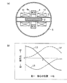
また、図中、P0をリング磁石4の軸方向の中心位置とすると、可動鉄心2の軸方向中心位置P1は、前記中心位置P0と一致して描いている。可動鉄心2の軸方向中心位置P1がリング磁石4の中心位置P0にあるときの該可動鉄心2の軸方向中心位置P1は、静止位置0(軸方向における振動中心位置:磁気抵抗最小位置)となる。この静止位置0は、前記中心位置P0と一致している。この場合の可動鉄心2の軸方向中心位置P1が静止位置0にあるときの該可動鉄心2の軸方向右側半分の長さと左側半分の長さは等長L2/2である。
Further, in the figure, if P0 is the center position in the axial direction of the
もし可動鉄心2が軸方向均質でない場合、可動鉄心2が静止位置にあっても、可動鉄心2の軸方向中心位置P1とリング磁石4の中心位置P0とが一致しない場合があるが、以下可動鉄心2の静止位置0でP1とP0とは一致するものとしておく。
If the
以上の構成により、第1の実施形態では、軸方向に貫通した貫通穴4aを有するリング磁石4と、前記貫通穴4a内を軸方向移動可能に配置された可動鉄心2とを備え、リング磁石4の軸方向中心位置P0と可動鉄心2の静止位置0とが一致した共振装置を構成しており、可動鉄心2に初動を与えて振動附勢すると、可動鉄心2が、パイプ3内を軸方向に振動することを可能としたものである。
With the above configuration, in the first embodiment, the
図1(b)を参照して、可動鉄心2のパイプ3中における軸方向位置に対し可動鉄心2に作用するリング磁石4の磁気吸引力の特性を説明する。L3は、その磁気吸引力の特性を示す特性線である。図1(b)において、横軸は、可動鉄心2のパイプ3内における軸方向位置を示し、横軸上の0は、可動鉄心2の静止位置を示す。横軸上の「→右」は、可動鉄心2の中心位置P1が静止位置0に対して右側の位置にあることを示し、横軸上の「左←」は、可動鉄心2の中心位置P1が静止位置0に対して左側の位置にあることを示す。また、縦軸は、可動鉄心2に作用するリング磁石4の磁気吸引力を示し、「0」は磁気吸引力がゼロであり、縦軸上の「→右」は、リング磁石4から可動鉄心2に作用する磁気吸引力の方向が「右」であって、かつ、その強さを示し、縦軸上の「←左」は、リング磁石4から可動鉄心2に作用する磁気吸引力の方向が「左」であって、かつその強さを示す。図1(b)に示すように、可動鉄心2の中心位置P1が静止位置0にあるときは、リング磁石4から可動鉄心2に作用する磁気吸引力は0である。
With reference to FIG.1 (b), the characteristic of the magnetic attraction force of the
このような可動鉄心2に作用するリング磁石4の磁気吸引力は、磁気抵抗が最小になるように可動鉄心2に作用し(リラクタンス力)、これにより可動鉄心2の中心位置P1が、リング磁石4の中心位置P0と一致するように作用し、つねに可動鉄心2を静止位置0に引き戻すような磁気吸引力を生じる。なお、図1(a)のリング磁石4は、軸方向に着磁されているが、半径方向に着磁されている場合でも同様のリラクタンス力を示す。
The magnetic attractive force of the
図1(b)に示すように、磁気吸引力は、所定範囲で可動鉄心2の位置に比例し、可動鉄心2を静止位置0に戻すように働く。例えば、可動鉄心2の軸方向中心位置P1が横軸上の静止位置0より右方(→右)になるほど、可動鉄心2をリング磁石4が左方向に吸引する磁気吸引力は大きくなり、可動鉄心2の中心位置P1が横軸上の静止位置0より左方(左←)になるほど、可動鉄心2をリング磁石4が右方向に吸引する磁気吸引力は大きくなる。そして、この磁気吸引力特性を示す特性線L3は、静止位置0を中心として右方(→右)および左方(左←)において所定範囲ではほぼ直線的つまり一定の傾斜勾配になっている。すなわち、第1の実施形態では、機械的なバネと同じ力―位置特性を持っており、バネと同様に、リング磁石4は、可動鉄心2の質量とともに共振装置を構成する。第1の実施形態における共振装置では、可動鉄心2に初動を与えて振動附勢すると、この可動鉄心2には共振周波数の過渡振動が生じる。
As shown in FIG. 1B, the magnetic attractive force is proportional to the position of the
〔第2の実施形態〕
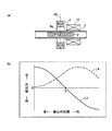
図2(a)は、本発明の第2の実施形態を示すものである。第2の実施形態では、図1(a)の可動鉄心2とリング磁石4とよりなる共振装置に、可動鉄心2の前記振動付勢用として第1のソレノイド12を加えた振動装置の構成となっている。第1のソレノイド12は、リング磁石4に対して図中、右方においてパイプ3の外周囲を包囲して配置されている。また、第1のソレノイド12の軸は、リング磁石4、可動鉄心2の軸と共通となっているが、第1のソレノイド12の軸方向の中心位置は可動鉄心2の静止位置と異なっている。
[Second Embodiment]
FIG. 2 (a) shows a second embodiment of the present invention. In the second embodiment, a configuration of a vibration device in which a
第1のソレノイド12が可動鉄心2に与える力は、可動鉄心2が第1のソレノイド12の発生する磁力に対して磁気抵抗最小の位置に移動するように働く(リラクタンス力)。これにより、第1のソレノイド12から可動鉄心2には、可動鉄心2を第1のソレノイド12の中心に移動させるように磁気吸引力が作用する。
The force applied to the
図2(b)は、図2(a)の振動装置における可動鉄心2に働く力を表したものであり、横軸および縦軸は、図1(b)の横軸および縦軸と同様である。図2(b)中、実線の特性線L3は図1(b)のそれと同様にリング磁石4によるものであり、破線の特性線L4は第1のソレノイド12により可動鉄心2に作用する磁気吸引力の特性を示す線である。特性線L4に示すように、第1のソレノイド12は、静止位置0付近にある可動鉄心2に対しては右方向に磁気吸引力を及ぼす。第1のソレノイド12は可動鉄心2が静止しているときは右方向に初動を与え、可動鉄心2が右方向に移動している間に第1のソレノイド12を励磁すると、右方向への移動速度が増大し、可動鉄心2の振動が附勢されて振幅が増大する。
FIG. 2B shows the force acting on the
リング磁石4により可動鉄心2内を通過する磁力線も、第1のソレノイド12の電流と作用して電磁力を生じるが、その電磁力はリラクタンス力ほど大きくはない。リラクタンス力は磁界の極性に無関係であるが、電磁力の方向はフレミングの左手の法則により磁界と電流の方向で決まる。第1のソレノイド12の電流の方向は、リング磁石4による可動鉄心2中の磁力線と同極性の磁力線が発生する方向とすれば、電磁力はリラクタンス力に加算される。
Magnetic field lines passing through the
図2(b)に示すように、第1のソレノイド12の磁気吸引力は、当該第1のソレノイド12の中心位置に可動鉄心2を引き込むように作用し、可動鉄心2が静止位置0付近にあるときは右方向に可動鉄心2を駆動する。
As shown in FIG. 2B, the magnetic attraction force of the
このように、共振装置に第1のソレノイド12を加えて共振装置の振動を附勢することが出来、振動を持続するには、振動附勢用のソレノイド12を毎振動周期中に所定の位相で短時間励磁する。これにより、持続振動する振動装置を構成することができる。
In this way, the
なお、第1のソレノイド12は、リング磁石4に対して図中、右方においてパイプ3の外周囲を包囲して配置されているが、リング磁石4に対して左方に配置されてもよい。
The
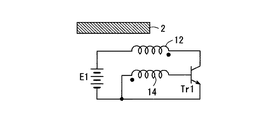
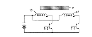
図3は、図2(a)の振動装置において、第1のソレノイド12の励磁回路の一例を示す。図3において、E1は直流電源、Tr1はnpn型のトランジスタである。第1のソレノイド12は、励振用として直流電源E1の正極とトランジスタTr1のコレクタとの間に直列に接続されている。14は、附勢用の第1のソレノイド12と電磁結合したフィードバックコイルであり、トランジスタTr1のベースとエミッタとの間に接続されている。励振用の第1のソレノイド12は、可動鉄心2に対して右方向に磁気吸引力を作用するので、可動鉄心2が右方向に移動している期間に励磁することによって振動を附勢することができる。第1のソレノイド12は、トランジスタTr1のオンオフによって、所定の期間、可動鉄心2を励磁する。
FIG. 3 shows an example of the excitation circuit of the
トランジスタTr1の駆動信号は、信号発生回路(図示せず)によって与えても良いが、第1のソレノイド12と結合したフィードバックコイル14によって与えることができる。
The drive signal for the transistor Tr1 may be given by a signal generation circuit (not shown), but can be given by a
可動鉄心2が軸方向右方に移動するときは、第1のソレノイド12中の磁束が増加し、第1のソレノイド12にE1側正,フィードバックコイル14にベース側正の電圧を誘起する。これにより、トランジスタTr1がオンに駆動され、第1のソレノイド12が直流電源E1より通電され、可動鉄心2に右方向の磁気吸引力が作用する。可動鉄心2が左方に移動するときは、フィードバックコイル14の誘起電圧が負となり、トランジスタTr1はオフである。その結果、振動が附勢される。
When the
〔第3の実施形態〕
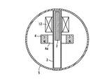
図4は、本発明の第3の実施形態を示すものである。図4では、図中の上下方向を重力が作用する向きとする。パイプ3は、軸方向を上下方向に一致させて配置すると共に、可動鉄心2を内部に挿入したパイプ3の外周囲にリング磁石4を配置し、リング磁石4より上側に第1のソレノイド12を配置する。この配置構成により、可動鉄心2は、図4中、上下方向に振動してベル5を連打してベル音を発生させる。第1のソレノイド12の磁気吸引力は強く、振動は正弦波状である必要はないので、ベル5の打棒となる可動鉄心2を駆動するのに適する。第1のソレノイド12の励磁期間と励磁周期とを制御することにより、ベル音の強さを調節することができる。パイプ3の前記した上下方向の配置は、パイプ3と可動鉄心2との摩擦を小さくする効果があり、下方向の励振には可動鉄心2に作用する重力を利用できる。
[Third Embodiment]
FIG. 4 shows a third embodiment of the present invention. In FIG. 4, the vertical direction in the figure is the direction in which gravity acts. The
〔第2の他の実施形態〕
図5(a)は、本発明の第2の他の実施形態を示すものである。図5(a)では、図2のリング磁石4と可動鉄心2とよりなる共振装置に第1のソレノイド12を加えたものに、さらに第2のソレノイド13が加えられている。第2のソレノイド13は、リング磁石4、第1のソレノイド12と可動鉄心2と軸を共通にするが、その中心位置はリング磁石4を挟んで第1のソレノイド12とは対称の位置にある。すなわち、第1のソレノイド12が可動鉄心2の静止位置の右にあれば、第2のソレノイド13は可動鉄心2の静止位置の左に配置される。
[Second Other Embodiment]
FIG. 5A shows a second other embodiment of the present invention. In FIG. 5A, a
〔第3の他の実施形態〕
図5(a)はまた、本発明の第3の他の実施形態を示すものである。パイプ3は図中、その長手方向を軸方向に一致させて配置され、これにより、可動鉄心2は左右方向に振動してベル5を連打する。第1のソレノイド12および第2のソレノイド13の磁気吸引力は強く、振動は正弦波状である必要はないので、ベルの打棒を駆動するのに適する。第1のソレノイド12と共に第2のソレノイド13の励磁期間で音の強さを調節することができる。可動鉄心2は半サイクルごとに附勢されるので強力に振動し、強いベル音を発生することができる。
[Third Other Embodiment]
FIG. 5 (a) also shows a third other embodiment of the present invention. In the drawing, the
図5(b)は、L3:リング磁石4、L4:第1のソレノイド12、L5:第2のソレノイド13の可動鉄心2に与える磁気吸引力特性を示す。第2のソレノイド13の磁気吸引力は、その中心位置に可動鉄心2を引き込むように作用し、可動鉄心2が静止位置付近にあるときは左方向に鉄心を駆動する。
FIG. 5B shows magnetic attractive force characteristics given to the
図6は、図5(a)の振動装置において第1、第2のソレノイド12、13の励磁回路の例を示す。励振用の第2のソレノイド13は、可動鉄心2に対して左方向に磁気吸引力を作用するので、可動鉄心2が左方向に移動している期間に励磁することによって振動を附勢することができる。第2のソレノイド13は、直列に接続されたトランジスタTr2のオンオフによって第1のソレノイド12とは逆の位相で所定の期間励磁する。
FIG. 6 shows an example of an excitation circuit for the first and
なお、実施形態では、リング磁石4は、1個であったが、起磁力を強くするうえでは、複数個とし、軸方向に密接して並置し等価的に図1(a)のL1を大きくしてもよい。
In the embodiment, the number of the
2 可動鉄心
3 パイプ
4 リング磁石
5 ベル
12 第1のソレノイド(励振用)
13 第2のソレノイド(励振用)
14 フィードバックコイル(発振用)
2
13 Second solenoid (for excitation)
14 Feedback coil (for oscillation)
Claims (3)
Priority Applications (1)
| Application Number | Priority Date | Filing Date | Title |
|---|---|---|---|
| JP2012278066A JP5661728B2 (en) | 2012-12-20 | 2012-12-20 | Resonance device, vibration device and bell ringing device |
Applications Claiming Priority (1)
| Application Number | Priority Date | Filing Date | Title |
|---|---|---|---|
| JP2012278066A JP5661728B2 (en) | 2012-12-20 | 2012-12-20 | Resonance device, vibration device and bell ringing device |
Publications (2)
| Publication Number | Publication Date |
|---|---|
| JP2014121663A true JP2014121663A (en) | 2014-07-03 |
| JP5661728B2 JP5661728B2 (en) | 2015-01-28 |
Family
ID=51402643
Family Applications (1)
| Application Number | Title | Priority Date | Filing Date |
|---|---|---|---|
| JP2012278066A Expired - Fee Related JP5661728B2 (en) | 2012-12-20 | 2012-12-20 | Resonance device, vibration device and bell ringing device |
Country Status (1)
| Country | Link |
|---|---|
| JP (1) | JP5661728B2 (en) |
Cited By (1)
| Publication number | Priority date | Publication date | Assignee | Title |
|---|---|---|---|---|
| JP2019055612A (en) * | 2017-09-19 | 2019-04-11 | Joyson Safety Systems Japan株式会社 | Steering wheel |
Citations (7)
| Publication number | Priority date | Publication date | Assignee | Title |
|---|---|---|---|---|
| JPS514759B1 (en) * | 1970-10-31 | 1976-02-14 | ||
| JPS5752787U (en) * | 1980-09-10 | 1982-03-26 | ||
| JPS603895U (en) * | 1983-06-18 | 1985-01-12 | 日本電気株式会社 | magnetic bell plunger |
| JPS61167367A (en) * | 1985-01-17 | 1986-07-29 | Mitsubishi Mining & Cement Co Ltd | Electromagnetic actuator |
| JP2001178103A (en) * | 1999-12-08 | 2001-06-29 | Shisei Chin | Magnet device |
| JP2002199689A (en) * | 2000-09-29 | 2002-07-12 | Matsushita Electric Works Ltd | Linear oscillator |
| JP5500659B2 (en) * | 2011-12-19 | 2014-05-21 | 大光電気株式会社 | Vibration device, bell ringing device, and resonance device |
-
2012
- 2012-12-20 JP JP2012278066A patent/JP5661728B2/en not_active Expired - Fee Related
Patent Citations (7)
| Publication number | Priority date | Publication date | Assignee | Title |
|---|---|---|---|---|
| JPS514759B1 (en) * | 1970-10-31 | 1976-02-14 | ||
| JPS5752787U (en) * | 1980-09-10 | 1982-03-26 | ||
| JPS603895U (en) * | 1983-06-18 | 1985-01-12 | 日本電気株式会社 | magnetic bell plunger |
| JPS61167367A (en) * | 1985-01-17 | 1986-07-29 | Mitsubishi Mining & Cement Co Ltd | Electromagnetic actuator |
| JP2001178103A (en) * | 1999-12-08 | 2001-06-29 | Shisei Chin | Magnet device |
| JP2002199689A (en) * | 2000-09-29 | 2002-07-12 | Matsushita Electric Works Ltd | Linear oscillator |
| JP5500659B2 (en) * | 2011-12-19 | 2014-05-21 | 大光電気株式会社 | Vibration device, bell ringing device, and resonance device |
Cited By (1)
| Publication number | Priority date | Publication date | Assignee | Title |
|---|---|---|---|---|
| JP2019055612A (en) * | 2017-09-19 | 2019-04-11 | Joyson Safety Systems Japan株式会社 | Steering wheel |
Also Published As
| Publication number | Publication date |
|---|---|
| JP5661728B2 (en) | 2015-01-28 |
Similar Documents
| Publication | Publication Date | Title |
|---|---|---|
| KR101157985B1 (en) | Linear type vibration motor | |
| US20200412228A1 (en) | Vibration motor | |
| JP2019201486A (en) | Linear vibration motor and electronic equipment | |
| CN104702078B (en) | Permanent magnet linear vibration motor and electrical equipment | |
| JP5500659B2 (en) | Vibration device, bell ringing device, and resonance device | |
| KR101557717B1 (en) | Linear Type Vibrator | |
| US20190006926A1 (en) | Linear vibration motor | |
| WO2021121055A1 (en) | Vibration apparatus | |
| WO2018058807A1 (en) | Linear vibration motor | |
| JPWO2016114383A1 (en) | Linear vibration motor | |
| JP2022077291A (en) | Linear vibration motor | |
| JP4422354B2 (en) | Electro-mechanical-acoustic transducer | |
| JP2009213952A (en) | Vibration generator | |
| JPWO2015122151A1 (en) | Electromagnetic relay | |
| KR101779290B1 (en) | Linear Vibration | |
| KR101197095B1 (en) | The vibration motor and electrostatic precipitator using that vibration motor as exciter | |
| JP5661728B2 (en) | Resonance device, vibration device and bell ringing device | |
| TW200621385A (en) | Flat oscillating actuator | |
| JP2017212793A (en) | Linear vibration motor | |
| JP2018001108A (en) | Linear vibration motor | |
| JP2016025818A (en) | Electric generator | |
| JPH10146035A (en) | Vibration generator mounting structure | |
| JP2021029064A (en) | Stepping motor | |
| JP2010029744A (en) | Vibration device and portable device | |
| JP2021029076A (en) | Stepping motor |
Legal Events
| Date | Code | Title | Description |
|---|---|---|---|
| A621 | Written request for application examination |
Free format text: JAPANESE INTERMEDIATE CODE: A621 Effective date: 20140728 |
|
| A871 | Explanation of circumstances concerning accelerated examination |
Free format text: JAPANESE INTERMEDIATE CODE: A871 Effective date: 20140803 |
|
| A975 | Report on accelerated examination |
Free format text: JAPANESE INTERMEDIATE CODE: A971005 Effective date: 20140827 |
|
| A131 | Notification of reasons for refusal |
Free format text: JAPANESE INTERMEDIATE CODE: A131 Effective date: 20140902 |
|
| A521 | Request for written amendment filed |
Free format text: JAPANESE INTERMEDIATE CODE: A523 Effective date: 20141029 |
|
| TRDD | Decision of grant or rejection written | ||
| A01 | Written decision to grant a patent or to grant a registration (utility model) |
Free format text: JAPANESE INTERMEDIATE CODE: A01 Effective date: 20141118 |
|
| A61 | First payment of annual fees (during grant procedure) |
Free format text: JAPANESE INTERMEDIATE CODE: A61 Effective date: 20141203 |
|
| R150 | Certificate of patent or registration of utility model |
Ref document number: 5661728 Country of ref document: JP Free format text: JAPANESE INTERMEDIATE CODE: R150 |
|
| R250 | Receipt of annual fees |
Free format text: JAPANESE INTERMEDIATE CODE: R250 |
|
| R250 | Receipt of annual fees |
Free format text: JAPANESE INTERMEDIATE CODE: R250 |
|
| R250 | Receipt of annual fees |
Free format text: JAPANESE INTERMEDIATE CODE: R250 |
|
| R250 | Receipt of annual fees |
Free format text: JAPANESE INTERMEDIATE CODE: R250 |
|
| R250 | Receipt of annual fees |
Free format text: JAPANESE INTERMEDIATE CODE: R250 |
|
| R250 | Receipt of annual fees |
Free format text: JAPANESE INTERMEDIATE CODE: R250 |
|
| LAPS | Cancellation because of no payment of annual fees |