JP2014113596A - Metal plate bending processing apparatus and bending processing method - Google Patents
Metal plate bending processing apparatus and bending processing method Download PDFInfo
- Publication number
- JP2014113596A JP2014113596A JP2012267060A JP2012267060A JP2014113596A JP 2014113596 A JP2014113596 A JP 2014113596A JP 2012267060 A JP2012267060 A JP 2012267060A JP 2012267060 A JP2012267060 A JP 2012267060A JP 2014113596 A JP2014113596 A JP 2014113596A
- Authority
- JP
- Japan
- Prior art keywords
- metal plate
- mold
- roll
- bending
- lower rolls
- Prior art date
- Legal status (The legal status is an assumption and is not a legal conclusion. Google has not performed a legal analysis and makes no representation as to the accuracy of the status listed.)
- Granted
Links
Images


Abstract
Description
本発明は、金属板を曲げ加工する装置および曲げ加工方法に関するものである。 The present invention relates to an apparatus for bending a metal plate and a bending method.
金属板を円筒状に曲げ加工するロールベンダー(曲げ加工装置)は、1本の上ロールと、該上ロールの斜め下方の左右に夫々配置した2本の下ロールとを備え、上ロールと下ロールとの間に挟持した金属板を、下ロールの回転によって送りつつ曲げ加工するよう構成されている(例えば、特許文献1参照)。 A roll bender (bending device) that bends a metal plate into a cylindrical shape includes one upper roll and two lower rolls arranged on the left and right sides of the upper roll obliquely below. The metal plate sandwiched between the rolls is bent while being fed by the rotation of the lower roll (see, for example, Patent Document 1).
前記3本ロール方式のロールベンダーでは、金属板が曲げ加工されて円筒状となった製品は上ロールの外側を囲むため、該上ロールの直径より小さな内径の製品を成形することはできない。従って、小さな内径の円筒状の製品を成形する場合は、それに合わせて上ロールの直径を小さくする必要があるが、小径の上ロールでは強度不足によってロール自体が橈んでしまって加工不良を生ずる問題があり、加工可能な寸法(内径)の自由度が低いものであった。なお、小径とした上ロールの強度不足を補うために、特許文献1のようにバックアップロールを用いる構成を採用することも考えられるが、この場合においても上ロールやバックアップロール等の複数のロールの外側を囲むように製品が成形されるため、加工可能な寸法(内径)の自由度を大きく向上することは困難であった。
In the three-roll type roll bender, a product obtained by bending a metal plate into a cylindrical shape surrounds the outer side of the upper roll, so that a product having an inner diameter smaller than the diameter of the upper roll cannot be formed. Therefore, when forming a cylindrical product with a small inner diameter, it is necessary to reduce the diameter of the upper roll accordingly. However, in the case of an upper roll with a small diameter, the roll itself is stagnated due to insufficient strength, resulting in processing defects. There was a low degree of freedom of dimensions (inner diameter) that can be processed. In order to compensate for the insufficient strength of the upper roll having a small diameter, it is possible to adopt a configuration using a backup roll as in
また、3本ロール方式のロールベンダーでは、金属板の端部に付与する曲げが不充分であったり、あるいは端部に曲げ加工が施されない未加工部分が発生する問題があった。このように金属板の端部に生ずる加工不良は、小径の製品を成形する場合に顕著であった。そこで、従来は、金属板を円筒状に曲げ加工する際には、プレス機を用いて金属板の端部を予め曲げ加工し、その後にロールベンダーで金属板の中間部分を曲げ加工していた。このように従来は、工場にロールベンダーとプレス機とを併設しなければならず、大きな設置スペースが必要になると共に設備費が嵩む問題が指摘される。 In addition, the three-roll type roll bender has a problem that the bending applied to the end of the metal plate is insufficient, or an unprocessed portion where the end is not bent is generated. Thus, the processing defect which arises in the edge part of a metal plate was remarkable when shape | molding a small diameter product. Therefore, conventionally, when bending a metal plate into a cylindrical shape, the end of the metal plate was previously bent using a press machine, and then the intermediate portion of the metal plate was bent using a roll bender. . As described above, conventionally, a roll bender and a press machine must be provided in the factory, which requires a large installation space and increases the equipment cost.
すなわち本発明は、前記従来の技術に内在する前記課題に鑑み、これを好適に解決するべく提案されたものであって、加工可能な寸法の自由度の高い金属板の曲げ加工装置および曲げ加工方法を提供することを目的とする。 That is, the present invention has been proposed in order to suitably solve the above-mentioned problems inherent in the conventional technology, and is a metal plate bending apparatus and bending process capable of being processed with a high degree of freedom. It aims to provide a method.
前記課題を克服し、所期の目的を達成するため、請求項1の発明に係る金属板の曲げ加工装置は、
金属板の移動方向の前後に離間する複数の下ロールと、
下ロール間の上方に位置し、下ロールの軸方向に延在する金型と、
前記金型を回転自在に支持する支持部材と、
前記金型を揺動する駆動手段と、
前記金型と下ロールとを相対的に近接離間移動する昇降手段とを備え、
前記金型は、揺動中心となる回転軸を中心とする円弧面が形成された弧状部と、回転軸を挟んで弧状部とは反対側に向けて径方向に延在する補強部とを備え、
前記下ロール間に位置する金属板に対して金型の弧状部を押付けて該金属板を加圧して曲げを付与するよう構成したことを要旨とする。
In order to overcome the above-mentioned problems and achieve the intended purpose, a metal plate bending apparatus according to the invention of
A plurality of lower rolls separated in the front-rear direction of the movement direction of the metal plate;
A mold located above the lower roll and extending in the axial direction of the lower roll;
A support member for rotatably supporting the mold;
Drive means for swinging the mold;
Elevating means for moving the mold and the lower roll relatively close to and away from each other, and
The mold includes an arc-shaped portion formed with an arc surface centering on a rotation axis serving as a swing center, and a reinforcing portion extending in a radial direction toward the opposite side of the arc-shaped portion across the rotation shaft. Prepared,
The gist is that the metal plate positioned between the lower rolls is pressed against the arc-shaped portion of the mold to press the metal plate to bend.
請求項1に係る発明によれば、弧状部および補強部を有する金型を用いて金属板を曲げ加工するよう構成したので、剛性を保ちつつ小さな曲率で金属板を曲げ加工することができ、加工可能な寸法の自由度を向上し得る。また、金型を揺動することで、金属板を移動させつつ曲げを付与することができ、精度良く金属板を曲げ加工し得る。
According to the invention of
請求項2に係る発明では、前記金型は支持部材に着脱自在に支持され、該支持部材は、下ロールとの間で金属板を加圧して曲げ加工可能な上ロールを回転自在に支持可能に構成されていることを要旨とする。
請求項2に係る発明によれば、金型を上ロールと交換することで、ロールベンダーとして用いることができる。すなわち、金型と上ロールとを交換することで、1台の装置によって金属板の端部を曲げ加工すると共に中間部分を曲げ加工して筒状に成形することができ、工場の設置スペースを削減できると共に設備コストを低減し得る。
In the invention according to claim 2, the mold is detachably supported by a support member, and the support member can rotatably support an upper roll that can be bent by pressing a metal plate with the lower roll. It is summarized as follows.
According to the invention which concerns on Claim 2, it can use as a roll bender by replacing | exchanging a metal mold | die with an upper roll. In other words, by exchanging the mold and the upper roll, it is possible to bend the end of the metal plate with a single device and bend the middle part into a cylindrical shape. It can be reduced and the equipment cost can be reduced.
前記課題を克服し、所期の目的を達成するため、請求項3の発明に係る金属板の曲げ加工方法は、
金属板の移動方向の前後に離間する2本の下ロールの内の一方の下ロールに金属板の移動方向の一端部を支持した状態で、2本の下ロールの軸心を結んだ線分の中央を通り該線分に垂直な基準垂線に対して一方の下ロール側へ偏倚させた金型を、該金型の円弧面が金属板に当接するように押付けて一端部を曲げ加工し、
前記金型を金属板から離間した状態で該金属板を移動して他端部を他方の下ロールで支持した状態で、前記基準垂線に対して他方の下ロール側へ偏倚させた金型を、前記円弧面が金属板に当接するように押付けて他端部を曲げ加工し、
前記金型と交換した上ロールを、2本の下ロールに支持された金属板の中間部分に押付けて曲げを付与した状態で、該上ロールおよび両下ロールを同時に正転駆動および逆転駆動して金属板を移動させつつ中間部分を曲げ加工することを要旨とする。
In order to overcome the above-mentioned problems and achieve the intended purpose, a metal plate bending method according to the invention of claim 3 comprises:
A line segment connecting the axis of the two lower rolls while one end of the two lower rolls separated from each other in the moving direction of the metal plate is supported on one end of the moving direction of the metal plate. One end of the die is bent by pressing a die that is biased toward one lower roll with respect to a reference perpendicular line that passes through the center of the die and is perpendicular to the line segment so that the arc surface of the die contacts the metal plate. ,
In a state where the metal plate is moved away from the metal plate and the other end portion is supported by the other lower roll, a die that is biased toward the other lower roll side with respect to the reference vertical line is provided. The other end is bent by pressing so that the arc surface comes into contact with the metal plate,
With the upper roll replaced with the mold pressed against the middle part of the metal plate supported by the two lower rolls, the upper roll and both lower rolls are simultaneously driven to rotate forward and reverse at the same time. The gist is to bend the intermediate portion while moving the metal plate.
請求項3に係る発明によれば、金型によって金属板の端部を曲げ加工した後、該金型と交換した上ロールを用いて金属板の中間部分を曲げ加工するようにしたので、剛性を有する金型によって金属板の端部を確実に曲げ加工することができ、加工可能な寸法の自由度を向上し得る。また、ロールベンダーとプレス機とを併用することなく1台の装置によって金属板を円筒状に成形し得るので、工場の設置スペースを削減できると共に設備コストを低減し得る。 According to the invention of claim 3, after bending the end portion of the metal plate with the mold, the intermediate portion of the metal plate is bent using the upper roll exchanged with the mold. The end portion of the metal plate can be reliably bent by the mold having, and the degree of freedom of dimensions that can be processed can be improved. Further, since the metal plate can be formed into a cylindrical shape by a single device without using both the roll bender and the press machine, the installation space of the factory can be reduced and the equipment cost can be reduced.
請求項4に係る発明では、前記金型により金属板の端部を曲げ加工するに際し、前記下ロールを正転駆動および逆転駆動すると共に金属板に押付けた金型を下ロールの駆動方向に合わせて揺動するようにしたことを要旨とする。
請求項4に係る発明によれば、金型を揺動することで、金属板を移動させつつ曲げを付与することができ、金属板の端部を精度良く曲げ加工し得る。
In the invention according to claim 4, when bending the end portion of the metal plate by the mold, the lower roll is driven forward and backward and the mold pressed against the metal plate is matched with the driving direction of the lower roll. The gist of this is to swing.
According to the fourth aspect of the present invention, the metal plate can be moved and bent by moving the mold, and the end portion of the metal plate can be bent with high accuracy.
本発明に係る金属板の曲げ加工装置および曲げ加工方法によれば、加工可能な曲げ寸法の自由度を向上し得る。 According to the metal plate bending apparatus and the bending method according to the present invention, the degree of freedom of the bendable dimensions can be improved.
次に、本発明に係る金属板の曲げ加工装置および曲げ加工方法につき、好適な実施例を挙げて、添付図面を参照しながら以下説明する。 Next, preferred embodiments of the metal plate bending apparatus and bending method according to the present invention will be described below with reference to the accompanying drawings.
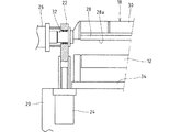
図1,図2は、実施例に係る金属板の曲げ加工装置10を示すものであって、該曲げ加工装置10は、一対の下ロール12,14と、該下ロール12,14の上方に昇降自在に配設され、両下ロール12,14間に支持されている金属板16に上方から当接して押下することで曲げを与える金型18とを基本的に備える。すなわち、曲げ加工装置10は、基礎フレーム20に、所要間隔離間して一対の昇降フレーム(支持部材)22,22が昇降自在に配設されると共に、該一対の昇降フレーム22,22間に金型18が回転自在に架設されている。各昇降フレーム22は、図3に示す如く、油圧シリンダ等の昇降手段24により昇降移動するよう構成され、一対(図3では一方のみ図示)の昇降手段24,24を同期して作動することで、金型18は平行に昇降動するよう構成される。一方の昇降フレーム22に駆動モータ(駆動手段)26が配設され、該駆動モータ26が金型18に連結されており、駆動モータ26を正転方向および逆転方向に回転駆動することで、金型18を揺動し得るよう構成してある(図4参照)。なお、金型18は、駆動モータ26によって回転(揺動)される際の回転軸(揺動中心)Oを通過する垂線Sに沿って昇降手段24,24で昇降動されて、金属板16に付与する曲率に応じた加工位置に位置決めされるよう構成してある。
1 and 2 show a
前記駆動モータ26が配設されていない他方の昇降フレーム22は、基礎フレーム20に対して昇降動自在で、かつ傾動自在に支持されている。そして、他方の昇降フレーム22と金型18との支持状態を解除したもとで、傾動機構27によって他方の昇降フレーム22を一方の昇降フレーム22から離間する方向に傾倒することで、一方の昇降フレーム22から金型18を引き抜いて交換し得るように構成されている。
The
前記金型18は、図2,図4に示す如く、該金型18の回転軸Oを中心とする円弧面28aが形成された弧状部28と、回転軸Oを挟んで弧状部28とは反対側に向けて径方向に延在する補強部30とを備え、弧状部28が下向きとなる姿勢で金型18が前記昇降フレーム22,22間に架設されている。実施例の円弧面28aは、周方向に180度の範囲で形成されている。また補強部30は、弧状部28の軸方向の全長に亘って設けられて、弧状部28が径方向に橈むのを抑制するべく機能する部分であって、該補強部30における径方向の長さは、弧状部28の半径より大きく設定されている。補強部30のより具体的な構成は、弧状部28における円弧面28aと同じ半径で弧状部28と同じ長さのロールを想定した場合に、該ロールより高い剛性が得られる厚みおよび径方向長さに補強部30が設定される。また、金型18の長手方向の両端部に軸部32が突設され、各軸部32が対応する昇降フレーム22に対して軸受を介して回動自在に支持されている(図3に一方のみ図示)。
As shown in FIGS. 2 and 4, the
前記金型18の下方には、図2に示す如く、基礎フレーム20に対して該金型18の回転軸Oと交差する方向(材料移動方向)に移動自在な移動台34が、材料移動方向に離間して一対配設されている。各移動台34には、図1に示す如く、金型18の回転軸Oと平行な下ロール12,14が夫々回転自在に配設されている。そして、各移動台34を流体圧シリンダ等の移動手段(図示せず)により移動させることにより、両下ロール12,14の軸心を結んだ線分の中央を通り該線分に垂直な基準垂線S0が、前記垂線Sに対して材料移動方向の前側または後側へ変位する位置に各下ロール12,14を移動可能に構成されている(図4(b),(c)参照)。すなわち、後述するように金属板16の端部を曲げ加工する際に、基準垂線S0に対して垂線Sが各下ロール12,14側へ偏倚した位置に金型18を臨ませ得るようになっている。また、2本の下ロール12,14は、図示しない回転駆動機構により同期して正転方向または逆転方向に回転するよう構成されている。更に、各移動台34には、対応する下ロール12,14を下側から支持するバックアップロール36が回転自在に支持されている。なお、実施例では、2本の下ロール12,14を区別する場合は、図2において左側の下ロール12を第1下ロールと指称すると共に、右側の下ロール14を第2下ロールと指称するものとする。また実施例では、図2において第2下ロール側から第1下ロール側への金属板16の移動方向を基準として、該金属板16の移動方向の前後を指称する。また、実施例において回転駆動機構により回転される下ロール12,14の正転方向および駆動モータ26により揺動される金型18の正転方向とは、下ロール12,14および金型18に当接する金属板16を第2下ロール側から第1下ロール側へ移動させる方向であり、逆転方向とは金属板16を第1下ロール側から第2下ロール側へ移動させる方向である。
Below the
実施例の曲げ加工装置10は、基本的な構成は、3本のロールによって金属板を円筒状に曲げ加工するロールベンダーと同じであって、上ロール40(図5参照)に代えて金型18を配設したことが異なっている。すなわち、金型18を回転する回転駆動機構、金型18を昇降動する昇降手段24、下ロール12,14を材料移動方向に移動する移動手段、下ロール12,14を回転する回転駆動機構は、公知のロールベンダーに用いられているものと同じである。そして、前記金型18を昇降フレーム22,22から取り外し、該昇降フレーム22,22に、下ロール12,14との間で金属板16を加圧して曲げ加工可能な上ロール40を回転自在に支持することで、ロールベンダーとして使用し得るよう構成されている。なお、上ロール40の軸端部には、金型18の軸端部に設けた軸部32と同一構成の軸部(図示せず)が設けられている。
The bending
前記基礎フレーム20に、前記金型18の高さ位置(下端位置)を検出する高さ検出手段38が配設され、該高さ検出手段38は図示しない制御手段に電気的に接続されている。そして、制御手段は、高さ検出手段38から入力される検出信号に基づいて、金型18が設定された高さ位置(加工位置)に維持されるように前記昇降手段24,24をフィードバック制御するよう構成される。これにより、2本の下ロール12,14と金型18とでの加圧下に曲げ加工される金属板16の加工精度を向上し得るようになっている。なお、高さ検出手段38は、昇降フレーム22,22に上ロール40を取り付けた際には、該上ロール40の高さ位置(下端位置)を検出するべく機能する。
A height detecting means 38 for detecting the height position (lower end position) of the
〔実施例の作用〕
次に、前述のように構成された本実施例の曲げ加工装置10の作用につき、曲げ加工方法との関係で説明する。
(Effects of Example)
Next, the operation of the bending
前記曲げ加工装置10では、金属板16を円筒状に曲げ加工する際には、先ず該金属板16の長手方向の端部を曲げ加工し、その後に両端部間の中間部分を曲げ加工する。なお、金属板16における端部の曲げ加工については、端曲げと指称するものとする。
In the
前記端曲げを行う場合は、前記金型18の回転軸Oを通る垂線Sが、両下ロール12,14の中央を通る前記基準垂線S0に対して第1下ロール12側へ偏倚した位置となるように両下ロール12,14を水平移動して位置決めする。また、金属板16に与える曲率に応じた離間間隔となるように2本の下ロール12,14の位置を調節する。そして、金属板16の材料移動方向の前端部が第1下ロール12上に位置するように該金属板16を両下ロール12,14に載置した状態で、金型18を、金属板16に与える曲率に応じた加工位置まで下降させる。そして、第1下ロール12と金型18とで金属板16の前端部を挟んだ状態で(図4(b)参照)、金型18と2本の下ロール12,14とを正転方向に駆動する。金型18および下ロール12,14の回転によって金属板16を所定量だけ前進させた後、金型18と2本の下ロール12,14とを逆転方向に駆動し、金属板16を前端部が金型18および第1下ロール12で挟持されなくなる直前まで後退移動して停止する。そして、2本の下ロール12,14の正転・逆転の動作を交互に反復すると共に、金型18を下ロール12,14と回転方向(駆動方向)に合わせて揺動することを所定回数繰り返すことで、金属板16を移動させつつ前端部に所定円弧のR曲げを与える。なお、前記駆動モータ26の正転・逆転による金型18の揺動角度は、前記弧状部28における円弧面28aが金属板16に当接している範囲で設定される。
When the end bending is performed, the perpendicular S passing through the rotation axis O of the
次に、前記金属板16の後端部の端曲げを行う。この後端部の端曲げは、金型18を金属板16から上方に離間する待機位置まで上昇したもとで、金型18の回転軸Oを通る垂線Sが、両下ロール12,14の中間を通る基準垂線S0に対して第2下ロール14側へ偏倚した位置となるように下ロール12,14を水平移動して位置決めする。そして、2本の下ロール12,14を正転駆動して金属板16を、該金属板16の材料移動方向の後端部が第2下ロール14上に位置するまで移動して停止する。この状態で、前記前端部の端曲げの場合と同様に、金型18を加工位置まで下降して第2下ロール14との間で金属板16の後端部を挟んだ状態で(図4(c)参照)、2本の下ロール12,14の正転・逆転の動作を交互に反復すると共に、金型18を下ロール12,14と回転方向(駆動方向)に合わせて揺動することを所定回数繰り返すことで、金属板16を移動させつつ後端部に所定円弧のR曲げを与える。
Next, end bending of the rear end portion of the
ここで、前記金属板16を移動しつつ端曲げを行う際に、金型18が加工位置から高さ方向にずれた場合は、前記高さ検出手段38からの検出信号に基づいて、前記制御手段が昇降手段24,24をフィードバック制御することで、金型18は加工位置に戻される。すなわち、金型18の高さ位置(加工位置)の変化をフィードバックすることで、金属板16の端部を精度よく曲げ加工することができる。
Here, when end bending is performed while moving the
前端部および後端部の端曲げが完了した金属板16における中間部分の曲げ加工に際しては、前記昇降フレーム22,22から金型18を取り外し、該昇降フレーム22,22に上ロール40を取り付ける。この状態で、該上ロール40の回転軸は、昇降フレーム22,22に金型18を取り付けた状態での該金型18の回転軸Oと同じ位置となる。そして、上ロール40の回転軸を通る垂線Sが、両下ロール12,14の中間を通る基準垂線S0と一致するように下ロール12,14を位置決めした状態で、金属板16における中間部分の曲げ加工を行なう(図5(a)参照)。すなわち、金属板16における中間部分の曲げ加工は、従来の3本方式のロールベンダーと同じであって、両下ロール12,14の間に臨む金属板16に対して上ロール40を待機位置から加工位置まで下降して金属板16を押し曲げた状態で、上ロール40と2本の下ロール12,14とを同時に正転駆動および逆転駆動することで、金属板16を移動させつつ所定円弧の曲げを与える(図5(b)参照)。すなわち、金属板16の中間部分に、3本のロール12,14,40で円筒となるような曲げを与えることで金属板16を円筒状に成形する。金属板16における中間部分の曲げ加工に際しても、前記高さ検出手段38からの検出信号に基づいて前記制御手段が昇降手段24,24をフィードバック制御することで、上ロール40を加工位置に維持することができ、金属板16を精度よく曲げ加工することができる。
When bending the intermediate portion of the
実施例の曲げ加工装置10は、金型18と上ロール40とを交換可能に構成したので、剛性の高い金型18によって金属板16の端部に確実に所定の曲率で曲げを与えることができると共に、該金属板16の中間部分は金型18と交換した上ロール40を用いて円筒状に成形することができる。すなわち、金属板16の端部を曲げるプレス機とロールベンダーとを別々に工場内に設置する必要はなく、工場内における設置スペースを削減し得ると共に設備コストを低減することができる。また、金型18による金属板16の端曲げに際して該金型18を揺動することで、金属板16の端部を精度良く曲げ加工することができる。
Since the bending
実施例の金型18は、金属板16に曲げを与える弧状部28の軸方向の全長に亘って補強部30が設けられているので、弧状部28における円弧面28aの半径を小さくしても剛性を維持することができる。すなわち、従来の3本ロール方式のロールべンダーに比べて、金属板16に曲率の小さな曲げを与えることができ、加工寸法の自由度が向上する。また、前記昇降フレーム22,22に対して金型18は着脱交換可能に支持されているので、金属板16に付与する曲率を変更する場合は、円弧面28aの半径が異なる別の金型18と交換することで簡単に対応することができる。なお、金型18について、補強部30および軸部32からなる本体に対して弧状部28を着脱自在に構成し、該弧状部28のみを交換することで金属板16に付与する曲率を変更するようにしてもよい。
In the
(別の曲げ加工方法について)
前記金型18によって前端部および後端部の端曲げが完了した金属板16における中間部分の曲げ加工については、前述したように金型18を上ロール40と交換して行うことに代えて、該金型18を用いて実施することができる。この金型18を用いた中間部分の曲げ加工に際しては、前記金型18の回転軸Oを通る垂線Sが、両下ロール12,14の中間を通る基準垂線S0と一致するように下ロール12,14を位置決めした状態で行なう(図6(a)参照)。この場合に、曲げ加工装置10では、端曲げされた金属板16における未加工の中間部分については、複数の領域に分割して金型18で曲げ加工を行なうため、該金型18で1回に加工可能な領域(材料移動方向の幅)に所定の曲率を与え得るように、2本の下ロール12,14の離間間隔を調節する。そして、端曲げされた金属板16について、図示しない支持手段によって前端部(加工部)に続く未加工部分が両下ロール12,14の間に臨むように金属板16を両下ロール12,14上に載置した状態に支持したもとで、金型18を待機位置から加工位置まで下降して所定幅で金属板16を押し曲げる。そして、端曲げの場合と同様に金型18と2本の下ロール12,14との正転・逆転の動作を交互に反復することを所定回数繰り返すことで、金属板16を移動させつつ所定円弧のR曲げを与える(図6(b)参照)。
(About another bending method)
For bending of the intermediate portion of the
次に、前記金型18を待機位置まで上昇し、両下ロール12,14を回転駆動して金属板16を、次の未加工部分が両下ロール12,14の間に臨む位置まで移動して停止した状態で、前述したと同様に金型18を待機位置から加工位置まで下降して所定幅で金属板16を押し曲げると共に、金型18と2本の下ロール12,14との正転・逆転の動作を交互に反復することを所定回数繰り返して金属板16の未加工に所定円弧のR曲げを与える。このようにして、金属板16の移動と金型18による曲げ加工とを繰り返すことで、金属板16の中間部分に円筒となるような曲げを与えることで金属板16を円筒状に成形する。金属板16における中間部分の曲げ加工に際しても、前記高さ検出手段38からの検出信号に基づいて前記制御手段が昇降手段24,24をフィードバック制御することで、金型18は加工位置に維持されて、金属板16を精度よく曲げ加工することができる。
Next, the
すなわち、金型18のみを用いて金属板16を円筒状に成形する場合は、円弧面28aの半径と同一の半径のロールと比較して、補強部30を備える金型18の剛性は高く、従来の3本ロール方式のロールべンダーに比べて、金属板16を小径の円筒状に成形することが可能となり、加工寸法の自由度が向上する。なお、別の曲げ加工方法において、金型18で1回に加工可能な領域(材料移動方向の幅)に所定の曲率を与える際に、2本の下ロール12,14の離間間隔を調節することに代えて、下ロール12,14の離間間隔を変えることなく材料移動方向の位置(垂線Sと基準垂線S0との材料移動方向の変位量)と金型18の加工位置とを調整することで対応可能である。
That is, when the
ここで、実施例の曲げ加工装置10では、円筒状の製品を成形する以外に、図7に示す如く、角筒状の製品を成形することができる。すなわち、金属板16を角筒状に成形する場合は、金型18の回転軸Oを通る垂線Sが、両下ロール12,14の中間を通る基準垂線S0と一致するように下ロール12,14を位置決めした状態で、金型18を下降して両下ロール12,14の間の金属板16を押下することで折曲して1つの角部を成形する。そして、金型18を待機位置まで上昇し、金属板16における別の角部となる予定部位を両下ロール12,14の間に位置させた状態で、金型18を下降して金属板16を押下することで折曲して角部を成形する。この工程を複数回(図示例では4回)繰り返すことで、平板状の金属板16から断面4角形の角筒状の製品を成形することができる。なお、金型18の下降位置を変更して金属板16の曲げ角度を変えることで、4角形に限らず5角形やその他多角形の角筒状の製品を成形し得る。また、角筒状の製品を成形する場合における加工中の金属板16については、ロボットその他の支持手段によって支持すると共に位置決めするようにすればよい。
Here, in the
〔変更例〕
本願は前述した実施例の構成に限定されるものでなく、その他の構成を適宜に採用することができる。
1.実施例では、両下ロールを夫々独立して水平方向に移動するよう構成したが、両下ロールを一定の軸心間距離に保持したもとで一体的に水平方向に移動する構成を採用し得る。
2.実施例では、両下ロールを水平移動することで、金型を、回転軸(垂線)が基準垂線より第1下ロール側または第2下ロール側に偏倚する位置に臨ませるよう構成したが、金型自体を水平方向に移動し得るよう構成して、該金型自体を水平方向に移動して回転軸(垂線)が基準垂線より第1下ロール側または第2下ロール側に偏倚する位置に臨ませる構成を採用することができる。
3.実施例では、金型を昇降手段によっ昇降動するよう構成したが、定位置に保持した金型に対して両下ロールを昇降手段によって昇降動することで、両下ロールに載置した金属板を金型との間で曲げ加工する構成を採用し得る。
4.実施例では、金型における弧状部の円弧面に関し、周方向に180度の範囲で形成した場合で説明したが、円弧面の周方向の形成範囲は180度より小さくても大きくてもよい。例えば、図8に示す如く、弧状部28における円弧面28aの周方向の形成範囲を180度より小さく設定し、円弧面28aの周方向の両端に接続する辺が相互に離間するように延在するよう形成することで、弧状部28を略扇形状としたものであってもよい。
[Example of change]
The present application is not limited to the configuration of the above-described embodiment, and other configurations can be appropriately employed.
1. In the embodiment, the lower rolls are configured to move independently in the horizontal direction, but a configuration is adopted in which the lower rolls are integrally moved in the horizontal direction while maintaining a constant distance between the center axes. obtain.
2. In the embodiment, the lower and upper rolls are moved horizontally, and the mold is configured to face the position where the rotation axis (perpendicular line) is biased to the first lower roll side or the second lower roll side from the reference vertical line. The mold itself can be moved in the horizontal direction, and the mold itself is moved in the horizontal direction so that the rotation axis (perpendicular line) deviates from the reference normal to the first lower roll side or the second lower roll side. It is possible to adopt a configuration that can be exposed to.
3. In the embodiment, the mold is moved up and down by the lifting means, but the metal placed on both the lower rolls by moving the lower rolls up and down by the lifting means with respect to the mold held in place. A configuration in which a plate is bent with a mold may be employed.
4). In the embodiment, the arc surface of the arc-shaped portion in the mold has been described as being formed in a range of 180 degrees in the circumferential direction, but the formation range in the circumferential direction of the arc surface may be smaller or larger than 180 degrees. For example, as shown in FIG. 8, the circumferential formation range of the
12 第1下ロール(下ロール)
14 第2下ロール(下ロール)
16 金属板
18 金型
22 昇降フレーム(支持部材)
24 昇降手段
26 駆動モータ(駆動手段)
28 弧状部
28a 円弧面
30 補強部
O 回転軸
S0 基準垂線
12 First lower roll (lower roll)
14 Second lower roll (lower roll)
24 Lifting means 26 Drive motor (drive means)
28 Arc-shaped
Claims (4)
下ロール(12,14)間の上方に位置し、下ロール(12,14)の軸方向に延在する金型(18)と、
前記金型(18)を回転自在に支持する支持部材(22,22)と、
前記金型(18)を揺動する駆動手段(26)と、
前記金型(18)と下ロール(12,14)とを相対的に近接離間移動する昇降手段(24)とを備え、
前記金型(18)は、揺動中心となる回転軸(O)を中心とする円弧面(28a)が形成された弧状部(28)と、回転軸(O)を挟んで弧状部(28)とは反対側に向けて径方向に延在する補強部(30)とを備え、
前記下ロール(12,14)間に位置する金属板(16)に対して金型(18)の弧状部(28)を押付けて該金属板(16)を加圧して曲げを付与するよう構成した
ことを特徴とする金属板の曲げ加工装置。 A plurality of lower rolls (12, 14) spaced apart from each other in the moving direction of the metal plate (16);
A mold (18) located above the lower roll (12, 14) and extending in the axial direction of the lower roll (12, 14);
A support member (22, 22) for rotatably supporting the mold (18);
Drive means (26) for swinging the mold (18);
Elevating means (24) for moving the mold (18) and the lower roll (12, 14) relatively close to and away from each other,
The mold (18) includes an arcuate part (28) formed with an arc surface (28a) centering on a rotation axis (O) serving as a center of oscillation, and an arcuate part (28) across the rotation axis (O). ) And a reinforcing portion (30) extending in the radial direction toward the opposite side,
The metal plate (16) located between the lower rolls (12, 14) is pressed against the arc-shaped portion (28) of the mold (18) to press the metal plate (16) and bend it. A metal plate bending apparatus characterized by that.
前記金型(18)を金属板(16)から離間した状態で該金属板(16)を移動して他端部を他方の下ロール(14)で支持した状態で、前記基準垂線(S0)に対して他方の下ロール(14)側へ偏倚させた金型(18)を、前記円弧面(28a)が金属板(16)に当接するように押付けて他端部を曲げ加工し、
前記金型(18)と交換した上ロール(40)を、2本の下ロール(12,14)に支持された金属板(16)の中間部分に押付けて曲げを付与した状態で、該上ロール(40)および両下ロール(12,14)を同時に正転駆動および逆転駆動して金属板(16)を移動させつつ中間部分を曲げ加工する
ことを特徴とする金属板の曲げ加工方法。 One end of the metal plate (16) in the moving direction is supported on one lower roll (12) of the two lower rolls (12, 14) separated from each other in the moving direction of the metal plate (16). Two lower rolls (12, 14) are biased toward one lower roll (12) with respect to a reference vertical line (S 0 ) passing through the center of the line connecting the axes of the lower rolls (12, 14). Pressing the mold (18) so that the arc surface (28a) of the mold (18) is in contact with the metal plate (16), bending one end,
In a state where the metal plate (16) is moved while the mold (18) is separated from the metal plate (16) and the other end is supported by the other lower roll (14), the reference perpendicular line (S 0 ) Is pressed to the other lower roll (14) side of the mold (18), the arc surface (28a) is pressed against the metal plate (16), the other end is bent,
The upper roll (40) exchanged with the mold (18) is pressed against the middle part of the metal plate (16) supported by the two lower rolls (12, 14) to bend the upper roll (40). A method of bending a metal plate, characterized in that the intermediate portion is bent while moving the metal plate (16) by simultaneously driving the roll (40) and both lower rolls (12, 14) to rotate forward and reverse.
Priority Applications (1)
| Application Number | Priority Date | Filing Date | Title |
|---|---|---|---|
| JP2012267060A JP5937958B2 (en) | 2012-12-06 | 2012-12-06 | Metal plate bending apparatus and bending method |
Applications Claiming Priority (1)
| Application Number | Priority Date | Filing Date | Title |
|---|---|---|---|
| JP2012267060A JP5937958B2 (en) | 2012-12-06 | 2012-12-06 | Metal plate bending apparatus and bending method |
Publications (2)
| Publication Number | Publication Date |
|---|---|
| JP2014113596A true JP2014113596A (en) | 2014-06-26 |
| JP5937958B2 JP5937958B2 (en) | 2016-06-22 |
Family
ID=51170174
Family Applications (1)
| Application Number | Title | Priority Date | Filing Date |
|---|---|---|---|
| JP2012267060A Expired - Fee Related JP5937958B2 (en) | 2012-12-06 | 2012-12-06 | Metal plate bending apparatus and bending method |
Country Status (1)
| Country | Link |
|---|---|
| JP (1) | JP5937958B2 (en) |
Cited By (3)
| Publication number | Priority date | Publication date | Assignee | Title |
|---|---|---|---|---|
| CN107649552A (en) * | 2017-09-21 | 2018-02-02 | 安徽墙煌彩铝科技有限公司 | A kind of aluminium plate arc flanging device and aluminium plate fold method |
| FR3062801A1 (en) * | 2017-02-15 | 2018-08-17 | Conception Machines Faveyrial | SHEET ROLLING MACHINE, AND METHOD FOR ROLLING A SHEET USING SUCH ROLLING MACHINE |
| KR20190045336A (en) * | 2016-10-11 | 2019-05-02 | 에스엠에스 그룹 게엠베하 | Molding press with bending blade |
Citations (5)
| Publication number | Priority date | Publication date | Assignee | Title |
|---|---|---|---|---|
| JPS57122729U (en) * | 1981-01-17 | 1982-07-30 | ||
| US4491004A (en) * | 1980-08-18 | 1985-01-01 | Ivanoff Osmo O | Apparatus for manufacturing a metal pipe |
| JPS60176819U (en) * | 1984-04-26 | 1985-11-22 | 日本鋼管株式会社 | bending roller |
| JPS62179820A (en) * | 1986-01-31 | 1987-08-07 | Hitachi Ltd | Method and device for iron plate bending |
| JPH0737422U (en) * | 1993-12-27 | 1995-07-11 | 第一興業株式会社 | Sheet metal bending machine |
-
2012
- 2012-12-06 JP JP2012267060A patent/JP5937958B2/en not_active Expired - Fee Related
Patent Citations (5)
| Publication number | Priority date | Publication date | Assignee | Title |
|---|---|---|---|---|
| US4491004A (en) * | 1980-08-18 | 1985-01-01 | Ivanoff Osmo O | Apparatus for manufacturing a metal pipe |
| JPS57122729U (en) * | 1981-01-17 | 1982-07-30 | ||
| JPS60176819U (en) * | 1984-04-26 | 1985-11-22 | 日本鋼管株式会社 | bending roller |
| JPS62179820A (en) * | 1986-01-31 | 1987-08-07 | Hitachi Ltd | Method and device for iron plate bending |
| JPH0737422U (en) * | 1993-12-27 | 1995-07-11 | 第一興業株式会社 | Sheet metal bending machine |
Cited By (6)
| Publication number | Priority date | Publication date | Assignee | Title |
|---|---|---|---|---|
| KR20190045336A (en) * | 2016-10-11 | 2019-05-02 | 에스엠에스 그룹 게엠베하 | Molding press with bending blade |
| KR102213572B1 (en) * | 2016-10-11 | 2021-02-08 | 에스엠에스 그룹 게엠베하 | Forming press with bending blades |
| FR3062801A1 (en) * | 2017-02-15 | 2018-08-17 | Conception Machines Faveyrial | SHEET ROLLING MACHINE, AND METHOD FOR ROLLING A SHEET USING SUCH ROLLING MACHINE |
| EP3363553A1 (en) * | 2017-02-15 | 2018-08-22 | Conception Machines Faveyrial | A rolling machine for metal sheets, as well as a method for rolling a metal sheet using such a rolling machine |
| CN107649552A (en) * | 2017-09-21 | 2018-02-02 | 安徽墙煌彩铝科技有限公司 | A kind of aluminium plate arc flanging device and aluminium plate fold method |
| CN107649552B (en) * | 2017-09-21 | 2024-02-09 | 安徽墙煌科技股份有限公司 | Arc-shaped aluminum plate flanging device and aluminum plate flanging method |
Also Published As
| Publication number | Publication date |
|---|---|
| JP5937958B2 (en) | 2016-06-22 |
Similar Documents
| Publication | Publication Date | Title |
|---|---|---|
| JP6077895B2 (en) | Turning roller device | |
| JP4615540B2 (en) | Long plate reversing device and long plate reversing method | |
| JPH04228226A (en) | Forming machine for bending plate into cylindrical shape | |
| JP5937958B2 (en) | Metal plate bending apparatus and bending method | |
| KR101742576B1 (en) | Grooving apparatus for metal plate | |
| JP6495726B2 (en) | Tube forming apparatus and tube forming method | |
| KR100805068B1 (en) | Apparatus for truning a rolling plate | |
| JP2016153137A (en) | Bending device and method of bending steel plate | |
| KR20130040998A (en) | Bending device for plate | |
| KR101184224B1 (en) | Correction apparatus for steel plate | |
| KR100949734B1 (en) | Leveling roll setting apparatus for leveler | |
| KR101818551B1 (en) | In-line forming apparatus and stacker for in-line forming apparatus | |
| JP2007290001A (en) | Flat die form rolling machine for worm | |
| KR100649280B1 (en) | Roll forming machine | |
| KR101869861B1 (en) | Roller apparatus for laminating flexible display in curved glass | |
| KR20120099355A (en) | Bending device for swing ring plate | |
| JP7462487B2 (en) | Metal bending method and device | |
| JP4948375B2 (en) | Guide roll segment for continuous casting | |
| JP5398014B2 (en) | Electric pipe squeeze mill | |
| JP3561540B2 (en) | Upper roll support device for roll bending device | |
| KR20120033035A (en) | Bending device for swing ring plate | |
| JP4189947B2 (en) | Molding press | |
| JP2020127963A (en) | Method of manufacturing noncircular pipe body and pipe body molding device | |
| JP3722936B2 (en) | Multi-sequential continuous distortion correction device | |
| JP3399312B2 (en) | Method and apparatus for bending edge of steel plate at the time of forming welded pipe |
Legal Events
| Date | Code | Title | Description |
|---|---|---|---|
| RD04 | Notification of resignation of power of attorney |
Free format text: JAPANESE INTERMEDIATE CODE: A7424 Effective date: 20141210 |
|
| A621 | Written request for application examination |
Free format text: JAPANESE INTERMEDIATE CODE: A621 Effective date: 20150724 |
|
| A977 | Report on retrieval |
Free format text: JAPANESE INTERMEDIATE CODE: A971007 Effective date: 20160414 |
|
| TRDD | Decision of grant or rejection written | ||
| A01 | Written decision to grant a patent or to grant a registration (utility model) |
Free format text: JAPANESE INTERMEDIATE CODE: A01 Effective date: 20160510 |
|
| A61 | First payment of annual fees (during grant procedure) |
Free format text: JAPANESE INTERMEDIATE CODE: A61 Effective date: 20160513 |
|
| R150 | Certificate of patent or registration of utility model |
Ref document number: 5937958 Country of ref document: JP Free format text: JAPANESE INTERMEDIATE CODE: R150 |
|
| R250 | Receipt of annual fees |
Free format text: JAPANESE INTERMEDIATE CODE: R250 |
|
| LAPS | Cancellation because of no payment of annual fees |