JP2014103458A - Camera module and display device - Google Patents
Camera module and display device Download PDFInfo
- Publication number
- JP2014103458A JP2014103458A JP2012252541A JP2012252541A JP2014103458A JP 2014103458 A JP2014103458 A JP 2014103458A JP 2012252541 A JP2012252541 A JP 2012252541A JP 2012252541 A JP2012252541 A JP 2012252541A JP 2014103458 A JP2014103458 A JP 2014103458A
- Authority
- JP
- Japan
- Prior art keywords
- camera module
- glass substrate
- liquid crystal
- crystal panel
- lens
- Prior art date
- Legal status (The legal status is an assumption and is not a legal conclusion. Google has not performed a legal analysis and makes no representation as to the accuracy of the status listed.)
- Pending
Links
Images


Abstract
Description
本発明は、表示装置とともに利用されるカメラモジュールに関する。 The present invention relates to a camera module used with a display device.
携帯電話、デジタルカメラ、またはスマートホンなど、液晶パネルを備えた携帯型の装置分野では、当該装置に撮影機能を付与するカメラモジュールを組み込むことが広く行われている。 In the field of portable devices including a liquid crystal panel such as a mobile phone, a digital camera, or a smart phone, it is widely performed to incorporate a camera module that gives a photographing function to the device.
例えば、特許文献1には、透過光量を変更させる液晶パネルと、当該液晶パネルと一体に設けられたレンズとから構成される光学ユニットを備え、レンズによって集光された被写体の光を結像させて撮影を行うとする撮影装置が開示されている。 For example, Patent Document 1 includes an optical unit that includes a liquid crystal panel that changes the amount of transmitted light and a lens that is provided integrally with the liquid crystal panel, and forms an image of the light of the subject that is collected by the lens. An imaging apparatus that performs imaging is disclosed.
また、特許文献2には、液晶表示部に表示データを映し出しながら、液晶表示部に内蔵したカメラにより撮影可能としているカメラ内蔵液晶ディスプレイ装置が開示されている。 Further, Patent Document 2 discloses a camera built-in liquid crystal display device capable of photographing with a camera built in the liquid crystal display unit while displaying display data on the liquid crystal display unit.
しかしながら、上述のような従来技術には、以下のような問題が存在する。 However, the following problems exist in the conventional technology as described above.
特許文献1に開示されている光学ユニットを備えた撮影装置では、液晶パネルの全面をレンズにしている。このため、当該撮影装置を、液晶パネルの一部分のみを活用するような利用形態に適用することが困難である。例えば、携帯電話のような装置では、映像表示および撮影を同時に行うニーズが強く、このようなニーズを満たす構成に、特許文献1に開示されている従来技術を適用することは困難と言わざるを得ない。 In the photographing apparatus provided with the optical unit disclosed in Patent Document 1, the entire surface of the liquid crystal panel is a lens. For this reason, it is difficult to apply the photographing apparatus to a usage form in which only a part of the liquid crystal panel is utilized. For example, in a device such as a mobile phone, there is a strong need for simultaneous video display and shooting, and it is difficult to apply the conventional technique disclosed in Patent Document 1 to a configuration that satisfies such a need. I don't get it.
特許文献2に開示されている従来技術では、液晶パネルの一部分を利用するとしているカメラ内蔵液晶ディスプレイが開示されているものの、レンズなどカメラの構成要素を、液晶パネル構成要素に、貫通していない孔を設けて単に埋め込み組みあわせただけの構成であるため、構成要素の数が多くなり、小型化および低コスト化が困難である。 The prior art disclosed in Patent Document 2 discloses a camera built-in liquid crystal display that uses a part of the liquid crystal panel, but does not penetrate the components of the camera such as a lens through the liquid crystal panel components. Since the structure is simply a combination of embedding and providing holes, the number of components increases, making it difficult to reduce the size and cost.
本発明は、上述の問題に鑑みて成されたもので、小型かつ低コストである液晶パネル一体型のカメラモジュールを提供することを目的とする。 The present invention has been made in view of the above-described problems, and an object of the present invention is to provide a liquid crystal panel integrated camera module that is small in size and low in cost.
上記の課題を解決するために、本発明の一態様に係るカメラモジュールは、イメージセンサと、上記イメージセンサ上に光を集光するレンズを固定しており、液晶パネルの不定領域におけるガラス基板を加工して形成された穴部に埋め込まれているレンズホルダとを備えている。 In order to solve the above problems, a camera module according to one embodiment of the present invention includes an image sensor and a lens that collects light on the image sensor, and a glass substrate in an indefinite region of the liquid crystal panel. And a lens holder embedded in a hole formed by processing.
本発明の一態様によれば、液晶パネルのガラス基板の一部の領域を、イメージセンサ上に光を集光するレンズを固定するレンズホルダを埋め込む領域として利用し、液晶パネルおよびカメラモジュールを一体化することができる。また、レンズホルダがガラス基板に埋め込まれることにより、少なくともレンズホルダを固定する筐体が必要なくなる。ゆえに、単純に液晶パネルおよびカメラモジュールを組み合わせた構成と比較して、構成要素数を削減することができる。さらに、上記レンズホルダLHは、上記液晶パネル10の不定領域における上記ガラス基板(上部ガラス基板10a、下部ガラス基板10b)を加工して形成された穴部に埋め込まれている。ここで、不定領域とは、液晶パネルにおいて映像の表示の用に不適な領域のことである。当該不定領域は、例えば、液晶パネルの端部領域に存在している。上記構成により、液晶パネルの不定領域を活用し、撮影機能を提供することができる。すなわち、小型かつ低コストである液晶パネル一体型のカメラモジュールを提供することができる効果を奏する。
According to one embodiment of the present invention, a liquid crystal panel and a camera module are integrated by using a partial region of a glass substrate of a liquid crystal panel as a region for embedding a lens holder that fixes a lens that collects light on an image sensor. Can be Further, since the lens holder is embedded in the glass substrate, at least a housing for fixing the lens holder is not necessary. Therefore, the number of components can be reduced as compared with a configuration in which a liquid crystal panel and a camera module are simply combined. Further, the lens holder LH is embedded in a hole formed by processing the glass substrate (
以下、本発明に係る実施の形態について、詳細に説明する。 Hereinafter, embodiments according to the present invention will be described in detail.
〔実施形態1〕
本発明に係る一実施形態において、図1〜図5に基づいて説明すれば、以下のとおりである。
Embodiment 1
In one embodiment according to the present invention, it will be described as follows based on FIGS.
<カメラモジュール1の構成>
図1は、本発明の一実施形態に係るカメラモジュール1の構成を示す斜視図である。図1に示すように、カメラモジュール1は、上部ガラス基板10aと、下部ガラス基板10bと、レンズ11を固定したレンズホルダLHと、イメージセンサ14と、後述する電子回路部15とを備えている。ここで、カメラモジュール1は、後述する液晶パネル10と一体的に形成されている。また、レンズ11は、光を透過して、イメージセンサ14上に当該光を集光する。換言すれば、レンズ11は、Z軸の正方向側から入射する光を透過して、Z軸に平行な一点鎖線で示す光軸に沿って光を導光し、イメージセンサ14上に当該光を集光している。なお、このような構成に限定されるわけではなく、レンズ11の光軸は、最終的に光をイメージセンサ14に集光することができるのであれば、Z軸に平行でなくてもよい。つまり、カメラモジュール1は、イメージセンサ14と、上記イメージセンサ14上に光を集光するレンズ11を固定しており、液晶パネル10の上部ガラス基板10aを加工して形成された穴部に埋め込まれているレンズホルダLHとを備えている。
<Configuration of camera module 1>
FIG. 1 is a perspective view showing a configuration of a camera module 1 according to an embodiment of the present invention. As shown in FIG. 1, the camera module 1 includes an
また、図1に示す座標軸について、X軸およびY軸は、各ガラス基板が平面的に広がっている方向に伸びる軸であり、Z軸は、各ガラス基板の厚さ方向に伸びる軸である。以下の説明および図における座標軸は、図1に示す座標軸と対応している。以下では、カメラモジュール1が備えている構成要素について詳細に説明する。 In addition, with respect to the coordinate axes shown in FIG. 1, the X axis and the Y axis are axes that extend in the direction in which each glass substrate spreads in a plane, and the Z axis is an axis that extends in the thickness direction of each glass substrate. The coordinate axes in the following description and drawings correspond to the coordinate axes shown in FIG. Below, the component with which the camera module 1 is provided is demonstrated in detail.
(上部ガラス基板10aおよび下部ガラス基板10b)
上部ガラス基板10aおよび下部ガラス基板10bは、後述の液晶パネル10を構成するガラス基板である。
(
The
図2(a)は、一般的な液晶パネルの積層構成を示す概略図である。本実施形態に係る液晶パネル10も、図2(a)に示す積層構成を有しており、液晶部21と、透明電極22aおよび透明電極22bと、カラーフィルタ23と、上部ガラス基板10aおよび下部ガラス基板10bと、偏光フィルタ24aおよび偏光フィルタ24bとを備えている。ここで、液晶部21は、透明電極22aおよび透明電極22bにより、所望の透過率分布に変化するように制御されている。そして、このような各構成要素を備えた液晶パネルでは、図示しないバックライトから出射される光を、偏光フィルタ24b、下部ガラス基板10b、透明電極22b、液晶部21、透明電極22a、カラーフィルタ23、上部ガラス基板10a、偏光フィルタ24aの順に透過させて、映像光として外部へ出射させることにより、映像を表示する。
FIG. 2A is a schematic diagram showing a laminated structure of a general liquid crystal panel. The
図2(b)は、カメラモジュール1を一体化するよりも以前の液晶パネル10の端部の概略構成を示す断面図である。図2(b)に示すように、上部ガラス基板10aと下部ガラス基板10bとが対向するように配されている。ここで、上部ガラス基板10aの厚さTaは、液晶パネル10の端部以外での上部ガラス基板10aの厚さtaと異なる大きさであってもよい。これにより、後述するレンズ11の加工において、所望の形状のレンズ11を得ることができる。また、下部ガラス基板10bの厚さTbは、液晶パネル10の端部以外での下部ガラス基板10bの厚さtbと異なる大きさであってもよい。また、上部ガラス基板10aの厚さTaと下部ガラス基板10bの厚さTbとは、異なる大きさであってもよい。なお、図2(b)のA−A´断面では、図2(a)に示す積層構成のように、液晶パネル10の各構成要素が積層されている。
FIG. 2B is a cross-sectional view showing a schematic configuration of the end portion of the
(レンズホルダLH)
上記レンズホルダLHは、上記液晶パネル10の不定領域における上記上部ガラス基板10aを加工して形成された穴部に埋め込まれている。ここで、不定領域とは、液晶パネル10において映像の表示の用に不適な領域のことである。当該不定領域は、例えば、液晶パネル10の端部領域に存在している。上記構成によれば、液晶パネル10の不定領域を活用し、撮影機能を提供することができる。また、レンズホルダLHの材質は、例えば、プラスチック、金属、またはガラスなどであってもよく、これらを組み合わせた材質であってもよい。また、レンズホルダLHは、透明であっても不透明であってもよく、例えば、黒色であってもよい。つまり、レンズホルダLHは、レンズ11を固定できるのであれば、どのような材質であってもよく、どのような透明状態(色)であってもよい。
(Lens holder LH)
The lens holder LH is embedded in a hole formed by processing the
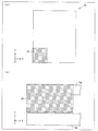
図3(a)は、液晶パネル10においてレンズホルダLHを埋め込む穴部を加工して形成する領域30の範囲を示す平面図である。図3(a)に示すように、レンズホルダLHを埋め込む穴部を形成する領域30は、破線で示す液晶パネル10の端部に位置している。図3(b)は、液晶パネル10のレンズホルダLHを埋め込む穴部を加工して形成する領域30の範囲を示す断面図である。図3(b)では、領域30を加工してレンズ11を形成するために、領域30における上部ガラス基板10aの厚さを、下部ガラス基板10bよりも大きくしている。一般的に、液晶パネルでは、端部領域において不定領域が存在しており、当該領域を有効に活用できることが好ましい。カメラモジュール1では、液晶パネル10の不定領域に含まれる領域30において、上部ガラス基板10aを加工してレンズホルダLHを埋め込む穴部を形成し、当該領域を有効に活用している。
FIG. 3A is a plan view showing a range of a
(レンズ11)
レンズ11は、レンズホルダLHに固定されており、イメージセンサ14上に光を集光する。ここで、レンズ11の形状は、例えば、両面凸形状、片面凸形状、または非球面形状などであってもよく、これらの形状を組み合わせた形状であってもよい。また、このような構成に限定されるわけではなく、イメージセンサ14上にレンズ11を透過した光を集光できるのであれば、どのような形状であってもよい。また、レンズ11の材質は、例えば、プラスチックまたはガラスなどであってもよく、これらを組み合わせた材質であってもよい。また、レンズ11の表面には、反射光量を低減する低反射コーディングがなされていてもよい。
(Lens 11)
The
(イメージセンサ14)
イメージセンサ14は、レンズ11を透過した光が集光されて、当該光を電気信号に変換する。ここで、イメージセンサ14は、1.2M−CMOS(Complementary Metal Oxide Semiconductor)を備えている。しかしながら、このような構成に限定されるわけではなく、イメージセンサ14は、例えば、CCD(Charge Coupled Device)を備えていてもよい。つまり、受光した光を適切に電気信号に光電変換するフォトダイオードとしての機能を実現可能な範囲において、イメージセンサ14に利用する素子の種類を選択することができる。また、イメージセンサ14は、COG(Chip On Glass)方式により、下部ガラス基板10b上に形成されている。以下では、上述のような構成要素を備えたカメラモジュール1を形成する方法について説明する。
(Image sensor 14)
The
<カメラモジュール1および液晶パネル10を一体化する構成>
図4(a)は、一般的なカメラモジュール1000の構成を示す概略図である。図4(a)に示すように、一般的なカメラモジュール1000は、レンズ1001と、LIDガラス1002と、レンズホルダ1003と、イメージセンサ1004と、フレキシブルプリント配線基板(FPC;Flexible Printed Circuit)1005と、FPC補強用部材1006とを備えている。ここで、FPC1005には、チップコンデンサ10051などのカメラモジュール1000に利用される電子部品が配されている。また、FPC補強用部材1006は、材質がSUSなどからなる。
<Configuration in which camera module 1 and
FIG. 4A is a schematic diagram illustrating a configuration of a
図4(b)は、図1に示すカメラモジュール1のようにレンズホルダLHを埋め込むよりも以前の液晶パネル10の端部の概略構成を示す断面図である。図4(b)に示すように、カメラモジュール1では、穴部加工領域33において、上部ガラス基板10aを加工し、穴部を形成する。また、下部ガラス基板10b上には、イメージセンサ14が、COG方式により形成されている。なお、下部ガラス基板10b上には、透明電極やチップコンデンサといったカメラモジュール1に利用される電子部品を含む電子回路部15が、さらに形成されていてもよい。このように、穴部加工領域33を加工して穴部を形成してレンズホルダLHを埋め込むことにより、液晶パネル10と一体化したカメラモジュール1を形成することができる。
FIG. 4B is a cross-sectional view showing a schematic configuration of the end portion of the
ここで、図4(a)に示す一般的なカメラモジュール1000の構成要素と、カメラモジュール1の構成要素とを比較すると、一般的なカメラモジュール1000が備える、FPC1005およびFPC補強用部材1006などの構成要素は、カメラモジュール1には形成されておらず、また、カメラモジュール1が機能するために必要とするわけでもない。また、カメラモジュール1では、一般的なカメラモジュール1000が備えるレンズホルダ1003が、上述の穴部加工領域33を加工して形成した穴部に埋め込んだレンズホルダLHにより実現されている。これにより、一般的なカメラモジュール1000と比較して、カメラモジュール1の構成部品数を削減し、低コスト化することができる。以下では、上述の加工を施した後のカメラモジュール1の構成について説明する。
Here, when the components of the
図5(a)は、図1に示すカメラモジュール1の断面構成を示すZX平面の断面図である。図5(a)に示すように、上部ガラス基板10aが加工され穴部が形成されレンズホルダLHが埋め込まれている。また、下部ガラス基板10bに、イメージセンサ14および電子回路部15が配されている。上記穴部は、当該穴部が形成されている上記上部ガラス基板10aを貫通している。上記構成によれば、レンズホルダLHを埋め込む穴部を形成するための上部ガラス基板10aの加工において、穴部の深さ方向の加工精度を考慮する必要がなくなる。これにより、カメラモジュール1を低コストに製造することができる。なお、当該穴部は、穴の形状が円形であり、例えば、当該円の直径が3mmであり、当該穴部の深さが1.5mm〜2.0mmであってもよい。
FIG. 5A is a sectional view of the ZX plane showing a sectional configuration of the camera module 1 shown in FIG. As shown in FIG. 5A, the
また、上記イメージセンサ14は、上記液晶パネル10の下部ガラス基板10bに配されており、当該下部ガラス基板10bと、上記穴部が形成された上部ガラス基板10aとは、異なるガラス基板である。上記構成によれば、液晶パネル10の下部ガラス基板10bの一部の領域を、イメージセンサ14を配する領域として利用し、液晶パネル10およびカメラモジュール1をさらに一体化することができる。また、イメージセンサ14が下部ガラス基板10bに配されることにより、少なくともイメージセンサ14を固定するためだけの基板が必要なくなる。ゆえに、単純に液晶パネルおよびカメラモジュールを組み合わせた構成と比較して、構成要素数を削減することができる。
The
ここで、レンズホルダLHの一部分は、長さl、厚さthの円筒形状を有している。なお、長さlおよび厚さthは、レンズホルダLHが、上部ガラス基板10aを加工して形成した穴部に安定して埋め込まれ、安定して固定され、レンズ11を安定して固定できる範囲において、任意に設定することができる。また、レンズホルダLHは、Z軸の正方向側に、厚さtcの固定部を備えている。当該固定部は、レンズホルダLHの端部をXY平面方向に広げた形状を有しており、上部ガラス基板10aに嵌合している。つまり、上記レンズホルダLHは、上記上部ガラス基板10aの一部分に嵌合している固定部を有している。上記構成によれば、固定部により、簡単にかつ安定してレンズホルダLHを上部ガラス基板10aに固定することができる。
Here, a part of the lens holder LH has a cylindrical shape having a length l and a thickness th. The length l and the thickness th are ranges in which the lens holder LH can be stably embedded and stably fixed in a hole formed by processing the
また、レンズ11の表面は、レンズ11を透過させた光を、距離f離れたイメージセンサ14上に集光させるような曲率を有するように加工されている。ここで、距離fは、例えば、35mm判フィルムカメラでの焦点距離に換算した値が2.05mm程度であってもよい。また、距離fは、カメラモジュール1に求められる画角およびイメージセンサ14のサイズに基づいて選択されてもよい。また、ある方向の画角をW、当該方向のイメージセンサのサイズをyとした場合には、それぞれの値と距離fとの関係は、次の式(1)により表現することができる。
Further, the surface of the
W=2tan−1{y/(2*f)} …(1)
つまり、距離fはイメージセンサ14のサイズにより変化してもよく、画角を一定に維持しつつイメージセンサ14を小さく(イメージセンサ14のピクセル数を少なく)した場合に、距離fは短くなってもよい。例えば、距離fは、0.8mmや1.0mmといった値であってもよい。
W = 2 tan −1 {y / (2 * f)} (1)
That is, the distance f may vary depending on the size of the
また、距離fを適切に選択することにより、レンズ11がレンズホルダLHの外部(上部ガラス基板10aの面であって下部ガラス基板10bと対向する面とは逆側の面よりもZ軸の正方向側の部分)へ突出しないように、レンズホルダLHはレンズ11を固定することができる。特に、距離fが短ければ、薄型の液晶パネルにおいて、レンズホルダLHを埋め込むガラス基板の厚さが薄い場合であっても、レンズ11がレンズホルダLHの外部へ突出していない、デザイン性に優れた液晶パネル一体型のカメラモジュールを提供することができる。
Further, by appropriately selecting the distance f, the
また、レンズ11が所望の曲率を有するように加工し、上述の距離fを確保するためには、レンズの厚さtを、一定の大きさ以上に確保できることが好ましい。このような距離fおよび厚さtを確保するために、上部ガラス基板10aの厚さTaを、一定以上の大きさにしてもよい。また、一定以上の厚さを確保するために、厚さTaは、液晶パネル10の端部以外での上部ガラス基板10aの厚さtaと異なる大きさにしてもよい。また、下部ガラス基板10bの厚さTbは、液晶パネル10の端部以外での下部ガラス基板10bの厚さtbと同じ大きさであるが、このような構成に限定されるわけではない。例えば、厚さTaを小さくし、厚さTbを大きくしてもよい。また、厚さTaおよび厚さTbの合計が、液晶パネル10として許容できる範囲に収まり、カメラモジュール1が撮影機能を提供できる範囲で、厚さTaおよび厚さTbを設定してもよい。
Further, in order to process the
また、液晶パネル10の端部のX軸方向の長さdexについても、カメラモジュール1が撮影機能を提供できるのであれば、どのように設定されてもよい。また、上部ガラス基板10aは、接触層35を介して下部ガラス基板10b上に固定されている。ここで、当該固定は、接着剤などにより行われてもよく、冶具などにより行われてもよく、上部ガラス基板10aおよび下部ガラス基板10bの接触層35側の領域が嵌め合わさる形状に各ガラス基板を加工して、各ガラス基板を嵌め合わせて行われてもよい。
Further, the length dex in the X-axis direction of the end portion of the
図5(b)は、図5(a)に対応する平面図である。なお、図5(b)にAx−Ax´で示す断面の構成が、図5(a)に示す断面構成に対応している。図5(b)に示すように、レンズホルダLHの固定部は、内径Di、外径Doのリング形状を有している。なお、内径Diおよび外径Doは、レンズホルダLHが上部ガラス基板10aを加工して形成した穴部に安定して埋め込まれ、安定して固定され、レンズ11を安定して固定可能なように、設定することができる。また、上部ガラス基板10aのX軸方向の端面からレンズホルダLHが埋め込まれている位置までのオフセット長さdxも、カメラモジュール1が撮影機能を提供できる範囲において設定し得る。例えば、長さdxを0としてもよい。上部ガラス基板10aのY軸方向の端面からレンズホルダLHが埋め込まれている位置までのオフセット長さdyについても、長さdxと同様である。
FIG. 5B is a plan view corresponding to FIG. Note that the cross-sectional configuration indicated by Ax-Ax ′ in FIG. 5B corresponds to the cross-sectional configuration illustrated in FIG. As shown in FIG. 5B, the fixed portion of the lens holder LH has a ring shape with an inner diameter Di and an outer diameter Do. The inner diameter Di and the outer diameter Do are stably embedded in the hole formed by processing the
図5(c)は、図1に示すカメラモジュール1の断面構成を示すYZ平面の断面図である。なお、図5(b)にAy−Ay´で示す断面の構成が、図5(c)に示す断面構成に対応している。図5(a)〜(c)に示すように、カメラモジュール1は、イメージセンサ14と、イメージセンサ14上に光を集光させるレンズ11を固定しており、液晶パネル10の上部ガラス基板10aを加工して形成された穴部に埋め込まれたレンズホルダLHとを備えている。
FIG. 5C is a cross-sectional view of the YZ plane showing a cross-sectional configuration of the camera module 1 shown in FIG. Note that the cross-sectional configuration indicated by Ay-Ay ′ in FIG. 5B corresponds to the cross-sectional configuration illustrated in FIG. As shown in FIGS. 5A to 5C, the camera module 1 fixes an
<カメラモジュール1の効果>
上記構成によれば、液晶パネル10の上部ガラス基板10aの一部の領域を、イメージセンサ14上に光を集光するレンズ11を固定するレンズホルダLHを埋め込む領域として利用し、液晶パネル10およびカメラモジュール1を一体化することができる。また、レンズホルダLHが上部ガラス基板10aに埋め込まれることにより、少なくともレンズホルダLHを固定する筐体が必要なくなる。ゆえに、単純に液晶パネルおよびカメラモジュールを組み合わせた構成と比較して、構成要素数を削減することができる。以下では、この構成要素数の削減について詳細に説明する。
<Effect of camera module 1>
According to the above configuration, a part of the
まず、図4(a)に示すように、一般的なカメラモジュール1000は、LIDガラス1002を除いても、レンズ1001と、レンズホルダ1003と、イメージセンサ1004と、FPC1005と、チップコンデンサ10051と、FPC補強用部材1006との、少なくとも6個の構成要素を備えている。ここで、液晶パネルの構成要素を、仮に、上部ガラス基板10aおよび下部ガラス基板10bの2個とするならば、当該液晶パネルの構成要素とカメラモジュール1000の構成要素とをあわせた構成要素の数は8個となる。
First, as shown in FIG. 4A, a
一方、図5(a)に示すように、本実施形態に係るカメラモジュール1は、レンズ11と、レンズホルダLHと、上部ガラス基板10aと、イメージセンサ14と、電子回路部15と、下部ガラス基板10bとの6個の構成要素を備えている。ここで、上部ガラス基板10aおよび下部ガラス基板10bは、カメラモジュール1と一体化している液晶パネル10の各ガラス基板と共用されているため、液晶パネル10の構成要素とカメラモジュール1の構成要素とをあわせた構成要素の数は6個となり、一般的なカメラモジュール1000と比較して、当該構成要素の数を2個削減可能であることが確認できる。
On the other hand, as shown in FIG. 5A, the camera module 1 according to this embodiment includes a
すなわち、小型かつ低コストである液晶パネル一体型のカメラモジュールを提供することができる。 That is, it is possible to provide a camera module integrated with a liquid crystal panel that is small and low-cost.
〔実施形態2〕
本発明の他の実施形態について、図6に基づいて説明すれば、以下のとおりである。なお、説明の便宜上、上記実施形態にて説明した図面と同じ機能を有する部材については、同じ符号を付記し、その説明を省略する。
[Embodiment 2]
The following will describe another embodiment of the present invention with reference to FIG. For convenience of explanation, members having the same functions as those in the drawings described in the above embodiment are given the same reference numerals, and descriptions thereof are omitted.
<カメラモジュール1aの構成および効果>
図6は、本発明の他の実施形態に係るカメラモジュール1aの断面構成を示す断面図である。図6に示すように、カメラモジュール1aは、カメラモジュール1が備える各構成要素に加えて、光学素子11aを備えている。ここで、光学素子11aは、カメラモジュール1のレンズホルダLHに追加する形で固定されている。また、光学素子11aは、光を透過させて、当該光の光学的性質を変化させる。
<Configuration and Effect of Camera Module 1a>
FIG. 6 is a cross-sectional view showing a cross-sectional configuration of a camera module 1a according to another embodiment of the present invention. As shown in FIG. 6, the camera module 1 a includes an
上記構成によれば、イメージセンサ14上に集光する光の光学的性質を変化させることができる。例えば、一般的なイメージセンサでは、特別なフィルタなどを利用しない場合には、ノイズとなる赤外光も検出してしまうことがある。しかしながら、光学素子11aが、例えばLIDガラスであって、透過させる光から赤外光を除去する機能を有していれば、当該イメージセンサ14に集光される光から、赤外光を除去することが可能となるので、イメージセンサ14の検出結果からノイズを除去することができる。つまり、構成要素の光学特性に起因する問題を解決し得るカメラモジュールを提供することができる。
According to the above configuration, the optical property of the light condensed on the
〔実施形態3〕
本発明の他の実施形態について、図7に基づいて説明すれば、以下のとおりである。なお、説明の便宜上、上記実施形態にて説明した図面と同じ機能を有する部材については、同じ符号を付記し、その説明を省略する。
[Embodiment 3]
The following will describe another embodiment of the present invention with reference to FIG. For convenience of explanation, members having the same functions as those in the drawings described in the above embodiment are given the same reference numerals, and descriptions thereof are omitted.
<カメラモジュール1bの構成および効果>
図7は、本発明の他の実施形態に係るカメラモジュール1bの断面構成を示す断面図である。図7に示すように、カメラモジュール1bでは、レンズホルダLHが2個(複数)のレンズ(レンズ11およびレンズ11b)を固定している点が、カメラモジュール1とは異なる。しかしながら、このような構成に限定されるわけではなく、レンズホルダLHが固定するレンズの個数は、3個以上であってもよい。また、レンズ11bは両面凹レンズであり、両面凸レンズであるレンズ11とは異なる形状を有している。しかしながら、このような構成に限定されるわけではなく、レンズ11の形状およびレンズ11bの形状は、各レンズが光軸を共有しており、光を透過して、イメージセンサ14上に当該光を集光することができれば、どのような形状であってもよい。例えば、レンズ11の形状およびレンズ11bの形状は、それぞれが異なる形状であっても、同様の形状であってもよく、両面凸形状、片面凸形状、両面凹形状、片面凹形状、または非球面形状などであってもよく、これらの形状を組み合わせた形状であってもよい。
<Configuration and effect of
FIG. 7 is a cross-sectional view showing a cross-sectional configuration of a
また、レンズ11とレンズ11bとの間の間隔daや、レンズ11bからイメージセンサ14までの距離fbなどは、イメージセンサ14上に上記光を集光することができるように、適宜定めてよい。つまり、上記レンズホルダLHは、光軸を共有する複数の上記レンズ11およびレンズ11bを固定しており、上記複数のレンズは、光を透過し、上記イメージセンサ14上に当該光を集光する。ここで、レンズが単数の場合には、光の色収差に起因して、光を所望の領域に集光できないことがある。上記構成によれば、レンズを複数利用して、光の色収差を補正することにより、光をイメージセンサ上の所望の位置に集光することができる。
Further, the distance da between the
〔カメラモジュール一体型の表示装置〕
本発明に係るカメラモジュールを一体化した表示装置について、図8に基づいて説明すれば、以下のとおりである。なお、説明の便宜上、上記実施形態にて説明した図面と同じ機能を有する部材については、同じ符号を付記し、その説明を省略する。
[Camera module integrated display device]
A display device in which the camera module according to the present invention is integrated will be described below with reference to FIG. For convenience of explanation, members having the same functions as those in the drawings described in the above embodiment are given the same reference numerals, and descriptions thereof are omitted.
<カメラモジュール一体型の表示装置50の構成および効果>
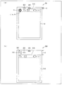
図8(a)は、本発明に係るカメラモジュールを一体化した表示装置50の概略構成を示す平面図である。図8(a)に示すように、表示装置50は、液晶パネル10と、センサ部502と、レシーバ部503と、上述のカメラモジュール(カメラモジュール1、1a、または1b)とを備えている。ここで、当該カメラモジュールのレンズ11は、ピクトエリア515の領域内に露出している。
<Configuration and Effect of Camera Module-
FIG. 8A is a plan view showing a schematic configuration of a
図8(b)は、図8(a)に示す表示装置50の比較例に係るカメラモジュール一体型の表示装置500の概略構成を示す平面図である。図8(b)に示すように、表示装置500は、液晶パネル510と、センサ部502と、レシーバ部503と、カメラモジュール501とを備えている。ここで、カメラモジュール501のレンズ511は、ピクトエリア515の領域外に露出している。つまり、液晶パネル510の端部に位置する不定領域を、カメラモジュール501を配するための領域として活用することができないため、表示装置500の額縁部の長さdが長くなっているが、図8(a)に示す本実施形態に係る表示装置50では、液晶パネル10の端部に位置する不定領域であるピクトエリア515の領域内にレンズ11が露出するようにカメラモジュールを埋め込めるため、表示装置500と比較して、額縁部の長さdを短くし、狭額縁化することができる。上記構成によれば、小型かつ低コストである液晶パネル一体型のカメラモジュールを備えた表示装置を提供することができる。
FIG. 8B is a plan view showing a schematic configuration of a camera module-integrated
また、表示装置50は、複数のカメラモジュールを備えていてもよい。さらに、上記複数のカメラモジュールが有している複数のレンズは、液晶パネル10のガラス基板の同一の面の側に配されていてもよい。上記構成によれば、例えば、複数のカメラモジュールにより視差を有した異なる複数の映像を撮影し、当該複数の映像に基づいた立体視用の撮影機能やステレオグラフィーを利用した距離測定機能を、携帯電話やスマートホンなどの表示装置に付与することができる。
The
〔まとめ〕
本発明の一態様に係るカメラモジュール(1、1a、1b)は、イメージセンサ14と、上記イメージセンサ14上に光を集光するレンズ11を固定しており、液晶パネル10の不定領域におけるガラス基板(上部ガラス基板10a、下部ガラス基板10b)を加工して形成された穴部に埋め込まれているレンズホルダLHとを備えている。
[Summary]
The camera module (1, 1 a, 1 b) according to one embodiment of the present invention fixes the
上記構成によれば、液晶パネルのガラス基板の一部の領域を、イメージセンサ上に光を集光するレンズを固定するレンズホルダを埋め込む領域として利用し、液晶パネルおよびカメラモジュールを一体化することができる。また、レンズホルダがガラス基板に埋め込まれることにより、少なくともレンズホルダを固定する筐体が必要なくなる。ゆえに、単純に液晶パネルおよびカメラモジュールを組み合わせた構成と比較して、構成要素数を削減することができる。さらに、上記レンズホルダLHは、上記液晶パネル10の不定領域における上記ガラス基板(上部ガラス基板10a、下部ガラス基板10b)を加工して形成された穴部に埋め込まれている。ここで、不定領域とは、液晶パネルにおいて映像の表示の用に不適な領域のことである。当該不定領域は、例えば、液晶パネルの端部領域に存在している。上記構成により、液晶パネルの不定領域を活用し、撮影機能を提供することができる。すなわち、小型かつ低コストである液晶パネル一体型のカメラモジュールを提供することができる。
According to the above configuration, the liquid crystal panel and the camera module are integrated by using a partial area of the glass substrate of the liquid crystal panel as an area for embedding the lens holder that fixes the lens that collects light on the image sensor. Can do. Further, since the lens holder is embedded in the glass substrate, at least a housing for fixing the lens holder is not necessary. Therefore, the number of components can be reduced as compared with a configuration in which a liquid crystal panel and a camera module are simply combined. Further, the lens holder LH is embedded in a hole formed by processing the glass substrate (
さらに、本発明の一態様に係るカメラモジュール(1、1a、1b)では、上記穴部は、当該穴部が形成されている上記ガラス基板(上部ガラス基板10a、下部ガラス基板10b)を貫通していてもよい。
Furthermore, in the camera module (1, 1a, 1b) according to one aspect of the present invention, the hole penetrates the glass substrate (
上記構成によれば、レンズホルダを埋め込む穴部を形成するためのガラス基板の加工において、穴部の深さ方向の加工精度を考慮する必要がなくなる。これにより、カメラモジュールを低コストに製造することができる。 According to the said structure, in the process of the glass substrate for forming the hole part which embeds a lens holder, it becomes unnecessary to consider the processing precision of the depth direction of a hole part. Thereby, a camera module can be manufactured at low cost.
さらに、本発明の一態様に係るカメラモジュール(1、1a、1b)では、上記イメージセンサ14は、上記液晶パネル10のガラス基板(下部ガラス基板10b)に配されており、当該ガラス基板と、上記穴部が形成されたガラス基板(上部ガラス基板10a)とは、異なるガラス基板であってもよい。
Furthermore, in the camera module (1, 1a, 1b) according to an aspect of the present invention, the
上記構成によれば、液晶パネルのガラス基板の一部の領域を、イメージセンサを配する領域として利用し、液晶パネルおよびカメラモジュールをさらに一体化することができる。また、イメージセンサがガラス基板に配されることにより、少なくともイメージセンサを固定するためだけの基板が必要なくなる。ゆえに、単純に液晶パネルおよびカメラモジュールを組み合わせた構成と比較して、構成要素数を削減することができる。 According to the above configuration, the liquid crystal panel and the camera module can be further integrated by using a partial area of the glass substrate of the liquid crystal panel as an area for arranging the image sensor. Further, since the image sensor is arranged on the glass substrate, at least a substrate only for fixing the image sensor is not necessary. Therefore, the number of components can be reduced as compared with a configuration in which a liquid crystal panel and a camera module are simply combined.
また、穴部を形成するガラス基板と、イメージセンサを配する(形成する)ガラス基板とを分けることにより、カメラモジュールの製造において、穴部およびイメージセンサの形成工程を分けることができる。これにより、カメラモジュールの製造工程の自由度が向上し、簡単かつ低コストにカメラモジュールを製造する余地を産むことができる。 Further, by separating the glass substrate on which the hole is formed and the glass substrate on which the image sensor is disposed (formed), the process of forming the hole and the image sensor can be separated in manufacturing the camera module. Thereby, the freedom degree of the manufacturing process of a camera module improves, and the room which manufactures a camera module easily and at low cost can be produced.
さらに、本発明の一態様に係るカメラモジュール(1、1a、1b)では、上記レンズホルダLHは、上記ガラス基板(上部ガラス基板10a、下部ガラス基板10b)の一部分に嵌合している固定部を有していてもよい。
Furthermore, in the camera module (1, 1a, 1b) according to one aspect of the present invention, the lens holder LH is fixed to a part of the glass substrate (
上記構成によれば、固定部により、簡単にかつ安定してレンズホルダをガラス基板に固定することができる。 According to the above configuration, the lens holder can be fixed to the glass substrate easily and stably by the fixing portion.
さらに、本発明の一態様に係るカメラモジュール1bでは、上記レンズホルダLHは、光軸を共有する複数の上記レンズ(11、11b)を固定しており、上記複数のレンズ11は、光を透過し、上記イメージセンサ14上に当該光を集光してもよい。
Furthermore, in the
ここで、レンズが単数の場合には、光の色収差に起因して、光を所望の領域に集光できないことがある。上記構成によれば、レンズを複数利用して、光の色収差を補正することにより、光をイメージセンサ上の所望の位置に集光することができる。 Here, when a single lens is used, light may not be collected in a desired region due to chromatic aberration of light. According to the above configuration, the light can be condensed at a desired position on the image sensor by using a plurality of lenses and correcting the chromatic aberration of the light.
さらに、本発明の一態様に係る表示装置50は、上記カメラモジュール(1、1a、1b)を備えていてもよい。
Furthermore, the
上記構成によれば、小型かつ低コストである液晶パネル一体型のカメラモジュールを備えた表示装置を提供することができる。 According to the above configuration, it is possible to provide a display device including a camera module integrated with a liquid crystal panel that is small and low in cost.
〔付記事項〕
本発明は上述した各実施形態に限定されるものではなく、請求項に示した範囲で種々の変更が可能であり、異なる実施形態にそれぞれ開示された技術的手段を適宜組み合わせて得られる実施形態についても本発明の技術的範囲に含まれる。さらに、各実施形態にそれぞれ開示された技術的手段を組み合わせることにより、新しい技術的特徴を形成することができる。
[Additional Notes]
The present invention is not limited to the above-described embodiments, and various modifications are possible within the scope shown in the claims, and embodiments obtained by appropriately combining technical means disclosed in different embodiments. Is also included in the technical scope of the present invention. Furthermore, a new technical feature can be formed by combining the technical means disclosed in each embodiment.
本発明は、液晶パネルを備えた応用製品に利用することができる。具体的には、テレビ、デジタルカメラ、ノート型パーソナルコンピュータ、タブレット型パーソナルコンピュータ、携帯電話、およびスマートホンなどにも利用することができる。 The present invention can be used for an application product including a liquid crystal panel. Specifically, the present invention can also be used for televisions, digital cameras, notebook personal computers, tablet personal computers, mobile phones, smart phones, and the like.
1 カメラモジュール
1a カメラモジュール
1b カメラモジュール
10 液晶パネル
10a 上部ガラス基板(ガラス基板)
10b 下部ガラス基板(ガラス基板)
11 レンズ
11a 光学素子
11b レンズ
14 イメージセンサ
50 表示装置
LH レンズホルダ
DESCRIPTION OF SYMBOLS 1 Camera module
10b Lower glass substrate (glass substrate)
11
Claims (5)
上記イメージセンサ上に光を集光するレンズを固定しており、液晶パネルの不定領域におけるガラス基板を加工して形成された穴部に埋め込まれているレンズホルダとを備えていることを特徴とするカメラモジュール。 An image sensor;
A lens for condensing light is fixed on the image sensor, and a lens holder embedded in a hole formed by processing a glass substrate in an indefinite region of the liquid crystal panel is provided. Camera module.
当該ガラス基板と、上記穴部が形成されたガラス基板とは、異なるガラス基板であることを特徴とする請求項1または2に記載のカメラモジュール。 The image sensor is disposed on the glass substrate of the liquid crystal panel,
The camera module according to claim 1, wherein the glass substrate and the glass substrate on which the hole is formed are different glass substrates.
Priority Applications (1)
| Application Number | Priority Date | Filing Date | Title |
|---|---|---|---|
| JP2012252541A JP2014103458A (en) | 2012-11-16 | 2012-11-16 | Camera module and display device |
Applications Claiming Priority (1)
| Application Number | Priority Date | Filing Date | Title |
|---|---|---|---|
| JP2012252541A JP2014103458A (en) | 2012-11-16 | 2012-11-16 | Camera module and display device |
Publications (1)
| Publication Number | Publication Date |
|---|---|
| JP2014103458A true JP2014103458A (en) | 2014-06-05 |
Family
ID=51025631
Family Applications (1)
| Application Number | Title | Priority Date | Filing Date |
|---|---|---|---|
| JP2012252541A Pending JP2014103458A (en) | 2012-11-16 | 2012-11-16 | Camera module and display device |
Country Status (1)
| Country | Link |
|---|---|
| JP (1) | JP2014103458A (en) |
Cited By (11)
| Publication number | Priority date | Publication date | Assignee | Title |
|---|---|---|---|---|
| CN108885376A (en) * | 2017-04-25 | 2018-11-23 | 华为技术有限公司 | The production method of LCD display, electronic equipment and LCD display |
| CN110622318A (en) * | 2019-08-12 | 2019-12-27 | 京东方科技集团股份有限公司 | Display device and method of manufacturing the same |
| CN110853497A (en) * | 2019-10-25 | 2020-02-28 | 武汉华星光电半导体显示技术有限公司 | Display panel and terminal device thereof |
| CN110865478A (en) * | 2018-08-27 | 2020-03-06 | 乐金显示有限公司 | Display device |
| WO2020173261A1 (en) * | 2019-02-26 | 2020-09-03 | 京东方科技集团股份有限公司 | Display panel and fabrication method therefor, and display device |
| JP2020528583A (en) * | 2017-08-05 | 2020-09-24 | ▲寧▼波舜宇光▲電▼信息有限公司 | An imaging module, an electronic device equipped with an imaging module, and a method for manufacturing the imaging module. |
| WO2020228395A1 (en) * | 2019-05-10 | 2020-11-19 | 武汉华星光电技术有限公司 | Display device |
| CN112019717A (en) * | 2020-08-19 | 2020-12-01 | 福建华佳彩有限公司 | High-definition display panel compatible with camera module under screen |
| WO2020249075A1 (en) * | 2019-06-14 | 2020-12-17 | 华为技术有限公司 | Display screen and electronic device |
| WO2021082268A1 (en) * | 2019-10-29 | 2021-05-06 | 北京小米移动软件有限公司 | Screen module and electronic device |
| US11366348B2 (en) | 2018-08-27 | 2022-06-21 | Lg Display Co., Ltd. | Display device |
-
2012
- 2012-11-16 JP JP2012252541A patent/JP2014103458A/en active Pending
Cited By (25)
| Publication number | Priority date | Publication date | Assignee | Title |
|---|---|---|---|---|
| CN110941112B (en) * | 2017-04-25 | 2024-01-05 | 华为技术有限公司 | LCD display screen, electronic equipment and manufacturing method of LCD display screen |
| CN108885376A (en) * | 2017-04-25 | 2018-11-23 | 华为技术有限公司 | The production method of LCD display, electronic equipment and LCD display |
| US11281252B2 (en) | 2017-04-25 | 2022-03-22 | Huawei Technologies Co., Ltd. | Liquid crystal display comprising an optical component having a component body that is competely or partially disposed in a pin through-hole in a backlight and electronic device having the same |
| CN110941112A (en) * | 2017-04-25 | 2020-03-31 | 华为技术有限公司 | LCD display screen, electronic equipment and manufacturing method of LCD display screen |
| US11048294B2 (en) | 2017-04-25 | 2021-06-29 | Huawei Technologies Co., Ltd. | Liquid crystal display comprising a front camera disposed inside a through hole that forms a light channel and extends through the liquid crystal display, electronic device comprising the same |
| JP2020528583A (en) * | 2017-08-05 | 2020-09-24 | ▲寧▼波舜宇光▲電▼信息有限公司 | An imaging module, an electronic device equipped with an imaging module, and a method for manufacturing the imaging module. |
| US11366348B2 (en) | 2018-08-27 | 2022-06-21 | Lg Display Co., Ltd. | Display device |
| US11966114B2 (en) | 2018-08-27 | 2024-04-23 | Lg Display Co., Ltd. | Display device |
| US11526047B2 (en) | 2018-08-27 | 2022-12-13 | Lg Display Co., Ltd. | Display device |
| CN110865478A (en) * | 2018-08-27 | 2020-03-06 | 乐金显示有限公司 | Display device |
| WO2020173261A1 (en) * | 2019-02-26 | 2020-09-03 | 京东方科技集团股份有限公司 | Display panel and fabrication method therefor, and display device |
| US11327353B2 (en) | 2019-02-26 | 2022-05-10 | Boe Technology Group Co., Ltd. | Display panel, manufacturing method thereof and display device |
| WO2020228395A1 (en) * | 2019-05-10 | 2020-11-19 | 武汉华星光电技术有限公司 | Display device |
| WO2020249075A1 (en) * | 2019-06-14 | 2020-12-17 | 华为技术有限公司 | Display screen and electronic device |
| US11476441B2 (en) | 2019-08-12 | 2022-10-18 | Beijing Boe Technology Development Co., Ltd. | Display apparatus and method of fabricating display apparatus |
| WO2021026721A1 (en) * | 2019-08-12 | 2021-02-18 | Boe Technology Group Co., Ltd. | Display apparatus and method of fabricating display apparatus |
| CN110622318A (en) * | 2019-08-12 | 2019-12-27 | 京东方科技集团股份有限公司 | Display device and method of manufacturing the same |
| CN110622318B (en) * | 2019-08-12 | 2023-01-10 | 京东方科技集团股份有限公司 | Display device and method of manufacturing the same |
| WO2021077606A1 (en) * | 2019-10-25 | 2021-04-29 | 武汉华星光电半导体显示技术有限公司 | Display panel and terminal apparatus used therefor |
| CN110853497A (en) * | 2019-10-25 | 2020-02-28 | 武汉华星光电半导体显示技术有限公司 | Display panel and terminal device thereof |
| JP2022511145A (en) * | 2019-10-29 | 2022-01-31 | ペキン シャオミ モバイル ソフトウェア カンパニー, リミテッド | Screen modules and electronic devices |
| US11184515B2 (en) | 2019-10-29 | 2021-11-23 | Beijing Xiaomi Mobile Software Co., Ltd. | Screen module and electronic device |
| JP7245234B2 (en) | 2019-10-29 | 2023-03-23 | ペキン シャオミ モバイル ソフトウェア カンパニー, リミテッド | screen module and electronics |
| WO2021082268A1 (en) * | 2019-10-29 | 2021-05-06 | 北京小米移动软件有限公司 | Screen module and electronic device |
| CN112019717A (en) * | 2020-08-19 | 2020-12-01 | 福建华佳彩有限公司 | High-definition display panel compatible with camera module under screen |
Similar Documents
| Publication | Publication Date | Title |
|---|---|---|
| JP2014103458A (en) | Camera module and display device | |
| TWI508547B (en) | Camera module | |
| US9883166B2 (en) | Three dimensional image pick-up device and manufacturing method thereof | |
| US9880391B2 (en) | Lens array modules and wafer-level techniques for fabricating the same | |
| KR102283111B1 (en) | Integrated microoptic imager, processor and display | |
| CN106803870B (en) | Camera module | |
| CN109743430A (en) | Display component and electronic device | |
| US20140118516A1 (en) | Solid state imaging module, solid state imaging device, and information processing device | |
| US20100033608A1 (en) | Camera module and method of manufacturing the same | |
| TWI471626B (en) | Camera module | |
| KR101442390B1 (en) | Camera module | |
| TW201008259A (en) | Assembly for image sensing chip and assembling method thereof | |
| CN110691153B (en) | Display module and terminal | |
| CN107895135B (en) | Iris scanning camera module and portable electronic device comprising same | |
| US9117719B2 (en) | Solid-state imaging apparatus, manufacturing method for the same, and electronic apparatus | |
| US8243185B2 (en) | Lens, lens module and camera module | |
| JP2014057271A (en) | Camera module and display device | |
| JP2008160348A (en) | Image-sensing lens module, camera module and method for mounting image-sensing lens module | |
| US7782388B2 (en) | Solid image pickup unit and camera module | |
| KR20130071078A (en) | Camera module | |
| JP2010278515A (en) | Camera module, and electronic apparatus with the same | |
| KR20070008276A (en) | Image sensor module for digital camera | |
| CN210109841U (en) | Optical fingerprint identification module and electronic equipment | |
| KR20100049405A (en) | Camera module | |
| KR101231433B1 (en) | Carmera module |