JP2014092554A - Image forming apparatus - Google Patents
Image forming apparatus Download PDFInfo
- Publication number
- JP2014092554A JP2014092554A JP2012240827A JP2012240827A JP2014092554A JP 2014092554 A JP2014092554 A JP 2014092554A JP 2012240827 A JP2012240827 A JP 2012240827A JP 2012240827 A JP2012240827 A JP 2012240827A JP 2014092554 A JP2014092554 A JP 2014092554A
- Authority
- JP
- Japan
- Prior art keywords
- recording medium
- sheet
- image forming
- image
- conveyance
- Prior art date
- Legal status (The legal status is an assumption and is not a legal conclusion. Google has not performed a legal analysis and makes no representation as to the accuracy of the status listed.)
- Pending
Links
Images


Classifications
-
- H—ELECTRICITY
- H04—ELECTRIC COMMUNICATION TECHNIQUE
- H04N—PICTORIAL COMMUNICATION, e.g. TELEVISION
- H04N1/00—Scanning, transmission or reproduction of documents or the like, e.g. facsimile transmission; Details thereof
- H04N1/00681—Detecting the presence, position or size of a sheet or correcting its position before scanning
- H04N1/00742—Detection methods
- H04N1/00748—Detecting edges, e.g. of a stationary sheet
-
- G—PHYSICS
- G03—PHOTOGRAPHY; CINEMATOGRAPHY; ANALOGOUS TECHNIQUES USING WAVES OTHER THAN OPTICAL WAVES; ELECTROGRAPHY; HOLOGRAPHY
- G03G—ELECTROGRAPHY; ELECTROPHOTOGRAPHY; MAGNETOGRAPHY
- G03G15/00—Apparatus for electrographic processes using a charge pattern
- G03G15/50—Machine control of apparatus for electrographic processes using a charge pattern, e.g. regulating differents parts of the machine, multimode copiers, microprocessor control
- G03G15/5029—Machine control of apparatus for electrographic processes using a charge pattern, e.g. regulating differents parts of the machine, multimode copiers, microprocessor control by measuring the copy material characteristics, e.g. weight, thickness
-
- G—PHYSICS
- G06—COMPUTING; CALCULATING OR COUNTING
- G06K—GRAPHICAL DATA READING; PRESENTATION OF DATA; RECORD CARRIERS; HANDLING RECORD CARRIERS
- G06K15/00—Arrangements for producing a permanent visual presentation of the output data, e.g. computer output printers
- G06K15/02—Arrangements for producing a permanent visual presentation of the output data, e.g. computer output printers using printers
- G06K15/18—Conditioning data for presenting it to the physical printing elements
- G06K15/1867—Post-processing of the composed and rasterized print image
- G06K15/1868—Post-processing of the composed and rasterized print image for fitting to an output condition, e.g. paper colour or format
-
- H—ELECTRICITY
- H04—ELECTRIC COMMUNICATION TECHNIQUE
- H04N—PICTORIAL COMMUNICATION, e.g. TELEVISION
- H04N1/00—Scanning, transmission or reproduction of documents or the like, e.g. facsimile transmission; Details thereof
- H04N1/00567—Handling of original or reproduction media, e.g. cutting, separating, stacking
- H04N1/0057—Conveying sheets before or after scanning
- H04N1/00572—Conveying sheets before or after scanning with refeeding for double-sided scanning, e.g. using one scanning head for both sides of a sheet
- H04N1/00575—Inverting the sheet prior to refeeding
- H04N1/00578—Inverting the sheet prior to refeeding using at least part of a loop, e.g. using a return loop
-
- H—ELECTRICITY
- H04—ELECTRIC COMMUNICATION TECHNIQUE
- H04N—PICTORIAL COMMUNICATION, e.g. TELEVISION
- H04N1/00—Scanning, transmission or reproduction of documents or the like, e.g. facsimile transmission; Details thereof
- H04N1/00567—Handling of original or reproduction media, e.g. cutting, separating, stacking
- H04N1/0057—Conveying sheets before or after scanning
- H04N1/00591—Conveying sheets before or after scanning from the scanning position
- H04N1/00594—Conveying sheets before or after scanning from the scanning position along at least a part of the same path as transport to the scanning position
-
- H—ELECTRICITY
- H04—ELECTRIC COMMUNICATION TECHNIQUE
- H04N—PICTORIAL COMMUNICATION, e.g. TELEVISION
- H04N1/00—Scanning, transmission or reproduction of documents or the like, e.g. facsimile transmission; Details thereof
- H04N1/00681—Detecting the presence, position or size of a sheet or correcting its position before scanning
- H04N1/00684—Object of the detection
- H04N1/00708—Size or dimensions
- H04N1/0071—Width
-
- H—ELECTRICITY
- H04—ELECTRIC COMMUNICATION TECHNIQUE
- H04N—PICTORIAL COMMUNICATION, e.g. TELEVISION
- H04N1/00—Scanning, transmission or reproduction of documents or the like, e.g. facsimile transmission; Details thereof
- H04N1/00681—Detecting the presence, position or size of a sheet or correcting its position before scanning
- H04N1/00729—Detection means
- H04N1/00734—Optical detectors
-
- H—ELECTRICITY
- H04—ELECTRIC COMMUNICATION TECHNIQUE
- H04N—PICTORIAL COMMUNICATION, e.g. TELEVISION
- H04N1/00—Scanning, transmission or reproduction of documents or the like, e.g. facsimile transmission; Details thereof
- H04N1/00681—Detecting the presence, position or size of a sheet or correcting its position before scanning
- H04N1/00763—Action taken as a result of detection
- H04N1/00774—Adjusting or controlling
- H04N1/00779—Adjusting settings, e.g. mode, feeding rate or type of paper
-
- G—PHYSICS
- G03—PHOTOGRAPHY; CINEMATOGRAPHY; ANALOGOUS TECHNIQUES USING WAVES OTHER THAN OPTICAL WAVES; ELECTROGRAPHY; HOLOGRAPHY
- G03G—ELECTROGRAPHY; ELECTROPHOTOGRAPHY; MAGNETOGRAPHY
- G03G2215/00—Apparatus for electrophotographic processes
- G03G2215/00362—Apparatus for electrophotographic processes relating to the copy medium handling
- G03G2215/00535—Stable handling of copy medium
- G03G2215/00717—Detection of physical properties
- G03G2215/00734—Detection of physical properties of sheet size
-
- G—PHYSICS
- G03—PHOTOGRAPHY; CINEMATOGRAPHY; ANALOGOUS TECHNIQUES USING WAVES OTHER THAN OPTICAL WAVES; ELECTROGRAPHY; HOLOGRAPHY
- G03G—ELECTROGRAPHY; ELECTROPHOTOGRAPHY; MAGNETOGRAPHY
- G03G2215/00—Apparatus for electrophotographic processes
- G03G2215/01—Apparatus for electrophotographic processes for producing multicoloured copies
- G03G2215/0103—Plural electrographic recording members
- G03G2215/0119—Linear arrangement adjacent plural transfer points
- G03G2215/0122—Linear arrangement adjacent plural transfer points primary transfer to an intermediate transfer belt
- G03G2215/0125—Linear arrangement adjacent plural transfer points primary transfer to an intermediate transfer belt the linear arrangement being horizontal or slanted
- G03G2215/0129—Linear arrangement adjacent plural transfer points primary transfer to an intermediate transfer belt the linear arrangement being horizontal or slanted horizontal medium transport path at the secondary transfer
Landscapes
- Engineering & Computer Science (AREA)
- Multimedia (AREA)
- Signal Processing (AREA)
- Physics & Mathematics (AREA)
- General Physics & Mathematics (AREA)
- General Engineering & Computer Science (AREA)
- Theoretical Computer Science (AREA)
- Microelectronics & Electronic Packaging (AREA)
- Control Or Security For Electrophotography (AREA)
- Controlling Sheets Or Webs (AREA)
Abstract
Description
本発明は、画像形成装置に関する。 The present invention relates to an image forming apparatus.
商業印刷業界では、小ロット・多品種・バリアブルデータ印刷等は従来のオフセット印刷機から、電子写真方式を用いた画像形成装置等によるPOD(Print On Demand)への移行が進んでいる。電子写真方式の画像形成装置では、この様なニーズに対応するため、オフセット印刷機に匹敵する表裏見当精度や画像の均一性等が要求される様になってきている。 In the commercial printing industry, small-lot, multi-variety, variable data printing, etc. is moving from a conventional offset printing machine to POD (Print On Demand) using an image forming apparatus using an electrophotographic method. In order to meet such needs, an electrophotographic image forming apparatus is required to have front and back registration accuracy comparable to an offset printing machine, image uniformity, and the like.
画像形成装置において生じる表裏見当ずれの要因は、縦方向・横方向のレジストレーション誤差、記録媒体と印刷画像とのスキュー誤差、トナー画像転写時の画像長伸縮に大別できる。さらに、定着装置を有する画像形成装置では、定着装置に加熱されることによって生じる記録媒体の伸縮による画像倍率誤差に起因して表裏見当ずれが発生する。 The causes of misregistration in the image forming apparatus can be broadly classified into vertical and horizontal registration errors, skew errors between the recording medium and the printed image, and image length expansion and contraction during toner image transfer. Further, in an image forming apparatus having a fixing device, a front / back misregistration occurs due to an image magnification error due to expansion / contraction of a recording medium caused by heating by the fixing device.
そこで、記録媒体としての用紙への画像印刷前後に、用紙の搬送方向及び搬送方向に直交する幅方向の寸法を検出し、検出結果から求められる寸法の変化に基づいて画像補正を行うことで、両面画像ズレを防止する技術が知られている(例えば、特許文献1参照)。 Therefore, before and after printing an image on a sheet as a recording medium, by detecting the dimension in the width direction perpendicular to the conveyance direction and the conveyance direction of the sheet, and performing image correction based on a change in the dimension obtained from the detection result, A technique for preventing double-sided image misalignment is known (see, for example, Patent Document 1).
しかしながら、上記した特許文献1の様に用紙の一方の面への印刷前後における用紙サイズの計測結果に基づいて画像倍率補正を行う方法では、搬送される用紙の先端検知後のカウンタ値等に基づく所定タイミングで用紙幅方向の寸法を計測するのが一般的である。
However, in the method of performing image magnification correction based on the measurement result of the paper size before and after printing on one side of the paper as in the above-mentioned
この様な方法では、例えば一方の面への印刷後に用紙をスイッチバック(用紙の裏表及び先端と後端を反転)して搬送する画像形成装置では、用紙の一方の面への印刷前の幅方向の寸法計測位置と、印刷後の幅方向の寸法計測位置とが異なる場合がある。この様な場合には、用紙への印刷前後において搬送方向の異なる位置で計測した幅寸法に基づいて印刷画像の倍率補正を行っても、用紙搬送方向の位置によって伸縮率が異なるため精度良く表裏見当ずれを補正できない場合がある。 In such a method, for example, in an image forming apparatus that transports paper by switching back (reversing the front and back and leading and trailing edges of the paper) after printing on one side, the width before printing on one side of the paper The dimension measurement position in the direction may be different from the dimension measurement position in the width direction after printing. In such a case, even if the magnification of the print image is corrected based on the width dimension measured at different positions in the transport direction before and after printing on the paper, the expansion / contraction rate differs depending on the position in the paper transport direction, so that the front and back surfaces are accurate. Misregistration may not be corrected.
本発明は上記に鑑みてなされたものであって、画像形成前後において記録媒体の搬送方向の同一位置で記録媒体の大きさを計測し、印刷画像の表裏見当精度を向上させることが可能な画像形成装置を提供することを目的とする。 The present invention has been made in view of the above, and can measure the size of the recording medium at the same position in the conveyance direction of the recording medium before and after the image formation, and can improve the front and back registration accuracy of the printed image. An object is to provide a forming apparatus.
本発明の一態様の画像形成装置によれば、記録媒体に画像を形成する画像形成手段と、前記画像形成手段により画像が形成された前記記録媒体を、表裏及び搬送方向の先端と後端とを反転させて再び前記画像形成手段に搬送する反転搬送手段と、前記画像形成手段による画像形成前後に、前記記録媒体の搬送方向に直交する幅方向の端部位置を計測する記録媒体幅計測手段と、前記記録媒体幅計測手段の計測結果から求められる前記記録媒体の形状変化に基づき、前記画像形成手段が後続の記録媒体に形成する画像を補正する補正手段と、を有し、前記記録媒体幅計測手段は、前記画像形成手段による画像形成前後に、前記記録媒体の搬送方向における一端からの距離が略同一となる計測位置で、前記記録媒体の前記幅方向の端部位置を計測する。 According to the image forming apparatus of one aspect of the present invention, the image forming unit that forms an image on the recording medium, and the recording medium on which the image is formed by the image forming unit are connected to the front and back and the leading and trailing ends in the transport direction. Reversing and conveying means for reversing and conveying the image to the image forming means again, and recording medium width measuring means for measuring end positions in the width direction perpendicular to the conveying direction of the recording medium before and after image formation by the image forming means And a correcting unit that corrects an image formed on the subsequent recording medium by the image forming unit based on a change in shape of the recording medium obtained from a measurement result of the recording medium width measuring unit, and the recording medium The width measuring unit measures the end position in the width direction of the recording medium at a measurement position where the distance from one end in the conveyance direction of the recording medium is substantially the same before and after the image formation by the image forming unit. That.
本発明の実施形態によれば、画像形成前後において記録媒体の搬送方向の同一位置で記録媒体の大きさを計測し、印刷画像の表裏見当精度を向上させることが可能な画像形成装置を提供できる。 According to the embodiment of the present invention, it is possible to provide an image forming apparatus capable of measuring the size of a recording medium at the same position in the conveyance direction of the recording medium before and after the image formation and improving the front and back registration accuracy of the printed image. .
以下、図面を参照して発明を実施するための形態について説明する。各図面において、同一構成部分には同一符号を付し、重複した説明を省略する場合がある。 Hereinafter, embodiments for carrying out the invention will be described with reference to the drawings. In the drawings, the same components are denoted by the same reference numerals, and redundant description may be omitted.
<画像形成装置の構成>
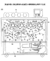
図1は、第1の実施形態に係る画像形成装置101の概略構成を例示する図である。
<Configuration of image forming apparatus>
FIG. 1 is a diagram illustrating a schematic configuration of an
画像形成装置101は、タンデム画像形成装置54、中間転写ベルト15、二次転写装置77を有する画像形成手段により、例えば用紙、OHP等の記録媒体としてのシートSに画像を形成する。
The
中間転写ベルト15は、画像形成装置101の中央付近に設けられ、複数のローラに掛け回されて図中時計周りに回転可能に構成されている。中間転写ベルト15は、回転駆動するローラ61に従動して回転する。
The
タンデム画像形成装置54は、中間転写ベルト15に沿って配置されている複数の現像装置53を有する。タンデム画像形成装置54の上部には、露光装置55が設けられている。タンデム画像形成装置54の各現像装置53は、各色のトナー像を担持する像担持体としての感光ドラム71を有する。
The tandem
また、感光ドラム71から中間転写ベルト15にトナー像を転写する一次転写位置には、中間転写ベルト15を間に挟んで各感光ドラム71に対向する位置に一次転写ローラ81が設けられている。
A primary transfer roller 81 is provided at a primary transfer position for transferring the toner image from the photosensitive drum 71 to the
二次転写装置77は、中間転写ベルト15を挟んでタンデム画像形成装置54と反対側(中間転写ベルト15の搬送方向下流側)に設けられている。二次転写装置77は、二次転写対向ローラとしてのローラ62に二次転写ローラ14を押し当てて転写電界を印加することで中間転写ベルト15上の画像をシートSに転写する。二次転写装置77は、転写条件のパラメータである二次転写ローラ14の転写電流を、シートSの種類等に応じて変化させる。
The
また、画像形成装置101は、シートSの形状を算出可能なシート搬送装置100を有し、後述する構成及び方法により搬送されるシートSの搬送方向の長さ、搬送方向に直交する幅方向の長さを計測し、シートSの形状を求めることができる。
Further, the
定着装置50は、熱源としてハロゲンランプ57を有し、無端ベルトである定着ベルト56に加圧ローラ52が押し当てられている。定着装置50は、定着条件のパラメータである定着ベルト56及び加圧ローラ52の温度、定着ベルト56と加圧ローラ52間のニップ幅、加圧ローラ52の速度をシートSに応じて変化させる。二次転写装置77から定着装置50へは、搬送ベルト41が画像転写後のシートSを搬送する。
The
画像形成装置101は、画像データが送られて作像開始の信号を受けると、不図示の駆動モータがローラ61を回転駆動して他の複数のローラを従動回転させ、中間転写ベルト15を回転させる。同時に、個々の現像装置53が、各感光ドラム71上にそれぞれの単色画像を形成する。そして、現像装置53で形成された単色画像は、回転駆動する中間転写ベルト15上に順次重ねて転写されて合成カラー画像を形成する。
In the
また、シートSは、給紙テーブル76の給紙ローラ72の1つが選択回転されることで、給紙カセット73の1つから繰り出されて搬送ローラ74により搬送されて、レジスト手段の一例としてのレジストローラ75に突き当てられて停止する。レジストローラ75は、シートSの搬送姿勢を補正し、中間転写ベルト15上の合成カラー画像が二次転写装置77に到達する画像形成タイミングに合わせて回転してシートSを搬送する。二次転写装置77に搬送されたシートSの表面には、中間転写ベルト15に形成されている合成カラー画像が転写される。
Further, the sheet S is fed out from one of the
画像転写後のシートSは、搬送ベルト41により搬送されて定着装置50へと送り込まれ、熱と圧力とを加えられて転写画像が溶融して定着する。シートSは、表面側に画像が定着された後、両面印刷の場合には分岐爪91およびフリップローラ92により、シート反転路93および両面搬送路94に搬送され、裏面側に合成カラー画像が形成される。
The sheet S after the image transfer is transported by the
また、シートSを反転させる場合は、分岐爪91がシート反転路93にシートSを導き、シートSを表面から裏面に反転させる。片面印刷及びシート反転無しの場合は、分岐爪91により、排紙ローラ95にシートSを搬送する。シート反転路93及び両面搬送路94は、シートSの反転搬送手段として、複数の搬送ローラにより一方の面の画像形成後のシートSの表裏及び搬送方向の先端と後端とを反転させ、再び二次転写装置77に向けてシートSを搬送する。
When the sheet S is reversed, the branching claw 91 guides the sheet S to the
その後、シートSは、排紙ローラ95によりデカーラユニット96に搬送される。デカーラユニット96では、デカーラローラ97の圧力を変えることでデカーラ量をシートSに応じて変化させ、カールを低減した後にシートSを機外に排出する。
Thereafter, the sheet S is conveyed to the decurler unit 96 by the
なお、シートSの搬送方向の位置及び搬送方向に直交する幅方向位置を補正するレジスト機構として、例えばレジストローラ75に代えてレジストゲート及びスキュー補正機構を設けても良い。この場合には、シート搬送装置100が、中間転写ベルト15上のトナー像が2次転写部に到達するタイミングで、シートSが2次転写部に到達する様にシートSを搬送する。本実施形態では、シート搬送装置100はシートSを一定の速度で搬送するが、搬送速度を可変に制御する様に構成しても良い。
As a registration mechanism for correcting the position in the conveyance direction of the sheet S and the position in the width direction orthogonal to the conveyance direction, for example, a registration gate and a skew correction mechanism may be provided instead of the
また、本実施形態に係る画像形成装置101は中間転写ベルト15上に形成されるカラートナー像をシートSに転写する構成であるが、複数の感光ドラム71に形成された単色トナー像をシートSに直接重ねて転写する構成であっても良い。また、本発明はモノクロ画像形成装置にも適用可能である。
The
図2は、実施形態に係る画像形成装置101の要部の概略構成を例示する図である。
FIG. 2 is a diagram illustrating a schematic configuration of a main part of the
図2に示す様に、画像形成装置101には、シートSの搬送経路にシート搬送装置100が設けられている。
As shown in FIG. 2, the
シート搬送装置100は、シートSを二次転写装置77に搬送すると共に、シートSの搬送方向の長さ、搬送方向に直交する幅方向の長さを計測し、シートSの形状を算出する。
The
シート搬送装置100は、両面印刷時に一方の面(表面)への画像形成前のシートSの形状、画像転写及び定着して一方の面(表面)への画像形成後に反転して搬送されるシートSの形状を計測し、画像形成前後におけるシートSの形状変化を求める。画像形成装置101は、シート搬送装置100において求められる両面印刷時のシートSの形状変化に基づいて、シートSの他方の面(裏面)に印刷する画像サイズをシート形状に合わせて倍率補正することで、表裏見当精度を向上させることができる。
The
ここで、シートSの両面印刷時において、シートSは表面印刷で定着装置50を通過する時に加熱及び加圧されることで伸縮して変形し、定着装置50を通過した後も温度の低下と共に変形し続ける。したがって、シートSの形状を求めて裏面側に印刷する画像の倍率補正を高精度に行うためには、画像をシートSに転写する直前でシートSの形状を求めることが望ましく、シート搬送装置100は、二次転写装置77の直上流に設けることが好ましい。
Here, at the time of double-sided printing of the sheet S, the sheet S is stretched and deformed by being heated and pressurized when passing through the fixing
<シート搬送装置の構成>
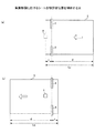
本実施形態に係る画像形成装置101のシート搬送装置100の構成を説明する。図3はシート搬送装置100の断面概略図であり、図4はシート搬送装置100の上面概略図である。
<Configuration of sheet conveying device>
A configuration of the
シート搬送装置100は、搬送手段の一例として、図示しない駆動手段(例えばモータ等)の駆動力を受けて回転駆動する駆動ローラ12、駆動ローラ12との間でシートSを挟持して従動回転する従動ローラ11を有する。
As an example of a conveying unit, the
また、従動ローラ11及び駆動ローラ12のシート搬送方向上流側には、レジストローラ75が設けられている。従動ローラ11及び駆動ローラ12のシート搬送方向下流側には、二次転写装置77が設けられている。
A
なお、図4に示す様に、従動ローラ11のシートSの搬送方向に直交する幅方向の長さWrは、シート搬送装置100が対応するシートSの最小幅Wsよりも小さく構成されている。したがって、従動ローラ11は、シートSの搬送時には駆動ローラ12に接触することが無いため、シートSとの間に生じる摩擦のみで従動回転することとなる。そのため、シートSの搬送時において従動ローラ11は、駆動ローラ12の影響を受けることなく、後述する方法によりシートSの搬送距離又は搬送方向の長さをより正確に求めることが可能になる。
As shown in FIG. 4, the length Wr of the driven
シート搬送装置100の従動ローラ11の回転軸上には、図3及び図4に示す様に、ロータリーエンコーダ18が設けられている。不図示のパルス計数手段が、回転するエンコーダディスク18aに形成されているスリットを検知してエンコーダセンサ18bが発生するパルス信号を計数することで、シートSの搬送量として従動ローラ11の回転量を計測する。
As shown in FIGS. 3 and 4, a
なお、本実施形態では、ロータリーエンコーダ18を従動ローラ11の回転軸上に設けているが、駆動ローラ12の回転軸上に設けても良い。なお、ロータリーエンコーダ18を取り付けるローラの径は小径である程、シート搬送に伴う回転数が増加してカウントするパルス量が多くなり、シートSの搬送距離又は搬送方向長さを高精度に求めることが可能になるため好ましい。
In this embodiment, the
また、ロータリーエンコーダ18を取り付ける従動ローラ11又は駆動ローラ12は、軸フレ精度を確保するために金属製のローラで構成することが好ましい。回転軸のフレを抑えることで、後述するシートSの搬送距離の計測を高精度に行うことが可能となる。
In addition, the driven
従動ローラ11及び駆動ローラ12のシートSの搬送方向の上流側及び下流側近傍には、センサ3,4が設けられている。センサ3,4は、搬送されるシートS端部の通過を検知する。センサ3,4には、例えばシート端部の検知精度が高い透過型又は反射型の光センサを用いることができ、本実施形態では反射型光センサを用いている。
従動ローラ11及び駆動ローラ12のシートSの搬送方向下流側のセンサ3は、シートSの先端部通過を検知する下流側検知手段としてのスタートトリガセンサ3である。また、従動ローラ11及び駆動ローラ12のシートSの搬送方向上流側のセンサ4は、シートSの後端部通過を検知する上流側検知手段としてのストップトリガセンサ4である。
A
スタートトリガセンサ3及びストップトリガセンサ4は、図4に示す様に、シートSの搬送方向に直交する幅方向位置が略同一に設けられている。この様に設けることで、シートSの搬送姿勢(搬送方向に対するスキュー)の影響を最小にし、より正確にシートSの搬送距離の計測を行うことが可能になる。
As shown in FIG. 4, the
なお、本実施形態では2つのセンサ3,4を、シートSの搬送方向に直交する幅方向の中央位置に配置しているが、シートSが通過する領域内であれば、中央位置から幅方向のいずれかの方向にずらして配置することもできる。
In the present embodiment, the two
また、シート搬送装置100は、シートSの搬送方向においてレジストローラ75と従動ローラ11との間に、ラインセンサ5を有する。ラインセンサ5は、記録媒体幅計測手段の一例であり、搬送されるシートSの幅方向両端部の位置を検出する。本実施形態では、ラインセンサ5として、シートSの幅方向両端部にそれぞれ1つずつラインセンサを設けているが、シートSの幅以上の長さを有する1つのラインセンサで、シートSの幅方向両端部の位置を検出しても良い。また、シートSの幅方向両端部の位置を計測可能であれば、例えばシートSの幅方向両端部に接触する突き当て部材を設け、突き当て部材の変位量に基づいて、シートSの幅を計測する構成であっても良い。
Further, the
図3及び図4に示す距離Aは、シートSの搬送経路におけるスタートトリガセンサ3と従動ローラ11及び駆動ローラ12との間の距離であり、距離Bはストップトリガセンサ4と従動ローラ11及び駆動ローラ12との間の距離である。距離A,Bは、後述するパルスカウント範囲が大きくなるため、可能な範囲で小さくすることが好ましい。
The distance A shown in FIGS. 3 and 4 is the distance between the
駆動ローラ12は、図3に示す矢印方向に回転しており、従動ローラ11は、シートSを搬送していない場合(空転時)には駆動ローラ12に従動回転し、シートSを搬送する場合には、シートSにより従動回転する。従動ローラ11が回転すると、回転軸上に設けられたロータリーエンコーダ18からパルスが発生する。
The driving
ロータリーエンコーダ18に接続する不図示のパルス計数手段が、搬送量計測手段の一例として、ロータリーエンコーダ18から出力されるパルスを計数することで、従動ローラ11及び駆動ローラ12によるシートSの搬送量を計測する。
A pulse counting unit (not shown) connected to the
シート搬送装置100は、以上で説明した構成を有し、シートSの搬送時にシートSの搬送距離又は搬送方向の長さ、搬送方向に直交する幅方向の長さを求めることができる。
The
<画像形成装置の機能構成>
図5は、実施形態に係る画像形成装置101の機能構成を例示するブロック図である。
<Functional configuration of image forming apparatus>
FIG. 5 is a block diagram illustrating a functional configuration of the
図5に示す様に、画像形成装置101は、スタートトリガセンサ3、ストップトリガセンサ4、ラインセンサ5、ロータリーエンコーダ18、シート形状算出手段20、パルス計数手段21、搬送距離算出手段22、画像データ補正手段23を有する。
As shown in FIG. 5, the
シート形状算出手段20は、搬送距離算出手段22によるシートSの搬送方向長さの算出結果及びラインセンサ5による幅方向の長さの計測結果に基づいて、シートSの形状を算出する。
The sheet
パルス計数手段21は、従動ローラ11に設けられているロータリーエンコーダ18のエンコーダディスク18aが回転することによってエンコーダセンサ18bから発生されるパルス信号を計数し、シートSの搬送量として従動ローラ11の回転量を計測する。
The pulse counting means 21 counts the pulse signal generated from the
搬送距離算出手段22は、スタートトリガセンサ3及びストップトリガセンサ4によるシートSの検知結果と、パルス計数手段21によって計測される従動ローラ11の回転量とに基づいて、シートSの搬送距離又は搬送方向の長さを算出する。
The conveyance
画像データ補正手段23は、補正手段の一例であり、シート形状算出手段20によって算出されたシートSの形状に基づいて、画像形成装置101がシートSに形成する画像サイズを補正する。
The image
画像形成装置101は、シート形状算出手段20によって算出されるシートSの形状に基づいて、画像データ補正手段23が画像データを補正することで、シートSの両面印刷において裏表見当精度の高い画像を印刷することが可能である。
In the
<シート形状の算出>
(シート搬送方向長さ)
次に、画像形成装置101におけるシートSの搬送距離及び搬送方向の長さを算出する方法について説明する。
<Calculation of sheet shape>
(Length in sheet conveyance direction)
Next, a method for calculating the transport distance and the length in the transport direction of the sheet S in the
図6に、本実施形態におけるスタートトリガセンサ3、ストップトリガセンサ4及びロータリーエンコーダ18の出力例を示す。
FIG. 6 shows an output example of the
上述した様に、従動ローラ11が回転すると、従動ローラ11の回転軸上に設けられたロータリーエンコーダ18からパルス信号が発生する。
As described above, when the driven
図6に示す例では、シートSの搬送開始後、時間t1にてストップトリガセンサ4がシートSの先端部通過を検知し、時間t2にてスタートトリガセンサ3がシートSの先端部通過を検知している。
In the example shown in FIG. 6, after the conveyance of the sheet S is started, the stop trigger sensor 4 detects passage of the leading edge of the sheet S at time t1, and the
続いて、時間t3にてストップトリガセンサ4がシートSの後端部通過を検知し、時間t4にてスタートトリガセンサ3がシートSの後端部通過を検知している。
Subsequently, the stop trigger sensor 4 detects passage of the rear end portion of the sheet S at time t3, and the
この時、時間t2にてシートSの先端部が通過したことをスタートトリガセンサ3が検知してから、時間t3にてシートSの後端部が通過したことをストップトリガセンサ4が検知するまでのパルスカウント時間に、パルス計数手段21がロータリーエンコーダ18のパルス計数を行う。
At this time, after the
ロータリーエンコーダ18が設けられた従動ローラ11の半径をrとし、従動ローラ11の1周分のエンコーダパルス数をN、パルスカウント時間に計数されたパルス数をnとする。このとき、時間t2から時間t3の間のシートSの搬送距離Ldは、下式(1)により求めることができる。
It is assumed that the radius of the driven
Ld = (n/N)×2πr ・・・(1)
n:計数されたパルス数
N:従動ローラ11の1周分のエンコーダパルス数[/r]
r:従動ローラ11の半径[mm]
一般的にシート搬送速度は、シートSを搬送するローラ(特に駆動ローラ12)の外形精度、芯フレ精度等の機械精度や、モータ等の回転精度、ギヤ、ベルト等の動力伝達機構の精度によって変動する。また、駆動ローラ12とシートSとの間のスリップ現象、上流側及び下流側の搬送手段のシート搬送力あるいはシート搬送速度の違いによる弛み現象等によっても変動するため、ロータリーエンコーダ18のパルス周期やパルス幅は常に変動するが、パルス数は変化することが無い。
Ld = (n / N) × 2πr (1)
n: Number of counted pulses N: Number of encoder pulses for one rotation of the driven roller 11 [/ r]
r: radius of the driven roller 11 [mm]
In general, the sheet conveyance speed depends on the mechanical accuracy such as the external accuracy of the roller (particularly the driving roller 12) that conveys the sheet S, the core flutter accuracy, the rotation accuracy of the motor, and the accuracy of the power transmission mechanism such as the gear and belt. fluctuate. Further, since it varies due to a slip phenomenon between the driving
したがって、シート搬送装置100に設けられる搬送距離算出手段22は、式(1)により、シート搬送速度に依存することなく、シート搬送手段としての従動ローラ11及び駆動ローラ12によるシートSの搬送距離Ldを高精度に求めることができる。
Therefore, the conveyance
また、搬送距離算出手段22は、例えばシートSのページ間の比や、表裏の比等の相対比を求めることもできる。
Further, the transport
搬送距離算出手段22は、例えば、画像形成装置101における画像形成前後のシート搬送距離の相対比から、伸縮率Rを下式(2)により求めることができる。
For example, the conveyance
R = [(n2/N)×2πr]/[(n1/N)×2πr] ・・・(2)
n1:熱定着前のシートSの搬送時に計数されたパルス数
n2:熱定着後のシートSの搬送時に計数されたパルス数
ここで、本実施形態において試算した例を以下で説明する。
R = [(n2 / N) × 2πr] / [(n1 / N) × 2πr] (2)
n1: Number of pulses counted during conveyance of the sheet S before thermal fixing n2: Number of pulses counted during conveyance of the sheet S after thermal fixing Here, an example calculated in the present embodiment will be described below.
本実施形態では、N=2800[/r]、r=9[mm]であり、A3サイズのシートが縦搬送された際に計数されたパルス数がn1=18816だった場合のシートSの搬送距離L1は、
L1 = (18816/2800)×2π×9 = 380.00[mm]
となる。
In this embodiment, N = 2800 [/ r], r = 9 [mm], and conveyance of the sheet S when the number of pulses counted when the A3 size sheet is conveyed vertically is n1 = 18816. The distance L1 is
L1 = (18816/2800) × 2π × 9 = 380.00 [mm]
It becomes.
また、このシートSの熱定着後に再度計数されたパルス数が、n2=18759だった場合のシートSの搬送距離L2は、
L2 = (18759/2800)×2π×9 = 378.86[mm]
となり、シートSの搬送距離の表裏差は、
ΔL = 380.00 − 378.86 = 1.14[mm]
であり、シートSの表裏の搬送距離の算出結果から、シートSの伸縮率R(シートSの表裏長さの相対比)を、
R = 378.86/380.00 = 99.70[%]
として求めることができる。
Further, when the number of pulses counted again after the thermal fixing of the sheet S is n2 = 18759, the conveyance distance L2 of the sheet S is
L2 = (18759/2800) × 2π × 9 = 378.86 [mm]
The difference between the front and back of the transport distance of the sheet S is
ΔL = 380.00−378.86 = 1.14 [mm]
From the calculation result of the conveyance distance of the front and back of the sheet S, the expansion ratio R of the sheet S (the relative ratio of the length of the front and back of the sheet S),
R = 378.86 / 380.00 = 99.70 [%]
Can be obtained as
したがって、この場合にはシートSの搬送方向の長さが熱定着によって約1mm収縮したために、シートS表裏の画像長を同一にすると約1mmの表裏見当ずれが発生することになる。そこで、画像データ補正手段23が、伸縮率Rに基づいて、シートSの裏面に印刷する画像長を補正することで、表裏見当精度を向上させることが可能になる。
Therefore, in this case, since the length of the sheet S in the conveyance direction contracts by about 1 mm due to thermal fixing, if the image lengths of the front and back sides of the sheet S are the same, a front / back misregistration of about 1 mm occurs. Accordingly, the image
なお、上記した例では、熱定着前後の搬送手段によるシートSの搬送距離L1,L2を算出して伸縮率Rを求めているが、例えば熱定着前後のシートSの搬送時に計数されたパルス数n1,n2の比を伸縮率Rとして求める伸縮率算出手段を設けても良い。 In the above-described example, the conveyance distances L1 and L2 of the sheet S by the conveyance unit before and after thermal fixing are calculated to obtain the expansion / contraction ratio R. For example, the number of pulses counted during conveyance of the sheet S before and after thermal fixing An expansion / contraction rate calculating means for obtaining the ratio of n1 and n2 as the expansion / contraction rate R may be provided.
例えば、上記した例において、熱定着前のシートSの搬送時に計数されたパルス数n1=18816、熱定着後のシートSの搬送時に計数されたパルス数n2=18759の時に、伸縮率Rは以下の様に求めることができる。 For example, in the above-described example, when the number of pulses n1 = 18816 counted during conveyance of the sheet S before heat fixing and the number of pulses n2 = 18759 counted during conveyance of the sheet S after heat fixing, the expansion / contraction ratio R is as follows: You can ask for it.
R = n2/n1 = 18759/18816 = 99.70[%]
なお、式(1)で求められる搬送距離Ldに、図3に示すスタートトリガセンサ3とストップトリガセンサ4との間の距離aを加えると、シートSの搬送方向の長さLpとなる。
R = n2 / n1 = 18759/18816 = 99.70 [%]
If the distance a between the
Lp = (n/N)×2πr+a ・・・(3)
a:スタートトリガセンサ3とストップトリガセンサ4との間の距離
この様に、シート搬送装置100の搬送距離算出手段22は、上式(1)によって求められるシート搬送手段によるシートSの搬送距離Ldに、センサ間の距離aを加えた式(3)により、シートSの搬送方向の長さLpを求めることができる。
Lp = (n / N) × 2πr + a (3)
a: Distance between the
また、搬送距離算出手段22は、電子写真方式による熱定着前後のシートSの搬送方向の長さLpの相対比から、伸縮率Rを下式(4)により求めることができる。
Further, the conveyance
R=[(n2/N)×2πr+a]/[(n1/N)×2πr+a] ・・・(4)
以上で説明した様に、画像形成装置101の搬送距離算出手段22は、高精度にシートSの搬送距離又は搬送方向の長さを求めることが可能であり、必要に応じて画像形成前後における伸縮率Rを求めることも可能である。
R = [(n2 / N) × 2πr + a] / [(n1 / N) × 2πr + a] (4)
As described above, the conveyance
なお、シートSの搬送方向の長さは、例えば搬送距離算出手段22が、スタートトリガセンサ3又はストップトリガセンサ4がシートSの搬送方向先端を検知してから後端を検知するまでの時間間隔と、搬送手段によるシートSの搬送速度とに基づいて求めても良い。
The length of the sheet S in the transport direction is, for example, the time interval from when the transport
(シート幅方向の長さ)
次に、画像形成装置101におけるシートSの搬送方向に直交する幅方向の長さを計測する方法について説明する。
(Length in the sheet width direction)
Next, a method for measuring the length in the width direction orthogonal to the conveyance direction of the sheet S in the
本実施形態では、シートSの一方の面への画像形成前に、シートSの搬送方向の先端付近及び後端付近の2箇所で幅方向の長さ(以下、「幅」という)を計測し、次に画像形成後に反転して搬送されるシートSに対して同様に2箇所で幅の計測を行う。 In this embodiment, before forming an image on one surface of the sheet S, the length in the width direction (hereinafter referred to as “width”) is measured at two locations near the leading edge and the trailing edge in the conveyance direction of the sheet S. Next, the width of the sheet S which is reversed and conveyed after the image formation is measured in the same manner at two locations.
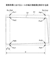
図7は、実施形態におけるシートSの幅計測位置を例示する図である。図7は、シート搬送装置100のうち、スタートトリガセンサ3、従動ローラ11及び駆動ローラ12、レジストローラ75等を省略して示している。
FIG. 7 is a diagram illustrating the width measurement position of the sheet S in the embodiment. FIG. 7 does not show the
ラインセンサ5は、ストップトリガセンサ4がシートSの搬送方向先端を検知してから時間T1経過後(図7(a))、及び時間T2経過後(図7(b))に、シートSの幅を計測する。
The
ここで、ストップトリガセンサ4がシートSの搬送方向先端を検知してから時間T1経過時におけるシートSの搬送方向先端から幅計測位置までの距離をcとし、時間T2経過時におけるシートSの搬送方向先端から幅計測位置までの距離をdとする。この時、距離cと距離dの合計値がシートSの搬送方向の長さLpとほぼ等しくなる様に、時間T1及びT2を設定する。 Here, the distance from the leading edge of the sheet S in the transport direction to the width measurement position after the time T1 has elapsed after the stop trigger sensor 4 detects the leading edge of the sheet S in the transport direction is c, and the transport of the sheet S when the time T2 has elapsed. Let d be the distance from the direction tip to the width measurement position. At this time, the times T1 and T2 are set so that the total value of the distance c and the distance d is substantially equal to the length Lp in the conveyance direction of the sheet S.
上記の条件でシートSの幅を計測した時のシートSの搬送状態を図8に示す。 FIG. 8 shows the conveyance state of the sheet S when the width of the sheet S is measured under the above conditions.
図8(a)は、シートSの一方の面への画像形成前にシートの幅を計測した後の状態であり、シートSの搬送方向先端から距離cの位置Pc1及び距離dの位置Pd1で、それぞれシートSの幅の計測が行われている。 FIG. 8A shows a state after the width of the sheet is measured before image formation on one surface of the sheet S. At a position Pc1 at a distance c and a position Pd1 at a distance d from the leading edge of the sheet S in the conveyance direction. The width of each sheet S is measured.
図8(b)は、シートSに両面印刷を行うために、シートSがシート反転路93でスイッチバックされ、両面搬送路94で再びシート搬送装置100に搬送される状態を示している。図8(b)に示す様に、シートSはシート反転路93でスイッチバックされることにより、搬送方向の先端と後端が入れ替わると共に、シート搬送装置100には裏表が反転された状態で搬送されることになる。したがって、スイッチバックされたシートSは、幅計測位置Pd1側が搬送方向先端、幅計測位置Pc1側が搬送方向後端になって搬送される。
FIG. 8B shows a state in which the sheet S is switched back by the
図8(c)は、シートSの一方の面への画像形成後であって、他方の面への画像形成前にシートSの幅を計測した後のシートSの搬送状態である。シートSは、シート搬送装置100を再び通過する際に、シートSの搬送方向先端からの距離c及び距離dで、ラインセンサ5による幅の計測が行われる。ここで、シートSの搬送方向先端から距離cの幅計測位置をPc2、距離dの幅計測位置をPd2とする。この時、幅計測位置Pc2は画像形成前の幅計測位置Pd1に、幅計測位置Pd2は画像形成前の幅計測位置Pc1に対応し、それぞれシートSの搬送方向の一端から略同一となる計測位置で、画像形成前後にシートSの幅を計測することとなる。
FIG. 8C shows the transport state of the sheet S after the image is formed on one side of the sheet S and after the width of the sheet S is measured before the image is formed on the other side. When the sheet S passes through the
上記した例では、合計がシートSの搬送方向の長さLpとなる搬送方向先端からの距離cと距離dでシートSの幅を計測することで、画像形成前後においてシートSの先端検知後に幅計測を行う時間T1、T2の設定を変えずに、反転搬送されるシートSの搬送方向の一端から略同一となる計測位置でのシートSの幅計測が可能になっている。 In the above-described example, the width of the sheet S is measured by the distance c and the distance d from the front end in the transport direction, which is the total length Lp in the transport direction of the sheet S, so that the width after the front end of the sheet S is detected before and after image formation. The width of the sheet S can be measured at substantially the same measurement position from one end in the conveyance direction of the sheet S to be conveyed in reverse without changing the settings of the measurement times T1 and T2.
なお、シートSは搬送方向にも伸縮する場合があるため、画像形成前後において正確に同一位置でシートSの幅を計測できなくなる可能性があるが、画像形成前後においてシートSの一端からの距離が略同一となる位置で幅の計測が可能であれば問題は無い。 Since the sheet S may expand and contract in the conveyance direction, there is a possibility that the width of the sheet S cannot be accurately measured at the same position before and after the image formation, but the distance from one end of the sheet S before and after the image formation. There is no problem as long as the width can be measured at a position where they are substantially the same.
例えば、A3サイズ(幅297mm、長さ420mm)のシートSを搬送する場合において、一方の面への画像形成後の収縮率が搬送方向先端側で幅0.3%、搬送方向後端側で幅0.5%、長さ0.5%で台形状に収縮した例を考える。この場合には、シートSの収縮によって、画像形成前後における幅の計測位置がずれて幅の計測値に誤差が生じることになる。しかし、幅の計測位置が搬送方向に5mmずれたとしても、この場合において幅の計測値の変化量は0.007mmであり、実質的に影響はないことから、画像形成前後における幅の計測位置は、シートSの一端からの距離が略同一となる位置であれば問題はない。 For example, when a sheet S of A3 size (width 297 mm, length 420 mm) is conveyed, the shrinkage rate after image formation on one surface is 0.3% width on the leading end side in the conveying direction and on the trailing end side in the conveying direction. Consider an example in which a trapezoid is contracted with a width of 0.5% and a length of 0.5%. In this case, due to the contraction of the sheet S, the width measurement position before and after the image formation is shifted, and an error occurs in the width measurement value. However, even if the width measurement position is deviated by 5 mm in the conveyance direction, the change amount of the width measurement value is 0.007 mm in this case, and there is substantially no influence. There is no problem as long as the distance from one end of the sheet S is approximately the same.
また、シート搬送経路においてシート搬送装置100の上流側でシートSの搬送方向長さLpを計測する手段を設け、計測されたシートSの搬送方向長さに基づいて、シートSの先端検知後に幅計測を行うまでの時間間隔を調整しても良い。画像形成前後におけるシートSの幅計測を正確に同一位置で行うことが可能になる。
Further, a means for measuring the length Lp in the conveyance direction of the sheet S is provided on the upstream side of the
図9は、実施形態におけるシートの幅計測結果を例示する図である。画像形成前のシートS1の形状を破線で、画像形成後のシートS2の形状を実線で示している。 FIG. 9 is a diagram illustrating a sheet width measurement result in the embodiment. The shape of the sheet S1 before image formation is indicated by a broken line, and the shape of the sheet S2 after image formation is indicated by a solid line.
図9に示す様に、画像形成前におけるシートS1の幅計測位置Pc1の両端部をそれぞれPcf1,Pcr1とし、幅計測位置Pd1の両端部をそれぞれPdf1,Pdr1とする。また、画像形成後におけるシートS2の幅計測位置Pc2の両端部をそれぞれPcf2,Pcr2とし、幅計測位置Pd2の両端部をそれぞれPdf2,Pdr2とする。 As shown in FIG. 9, both ends of the width measurement position Pc1 of the sheet S1 before image formation are Pcf1 and Pcr1, respectively, and both ends of the width measurement position Pd1 are Pdf1 and Pdr1, respectively. Further, both ends of the width measurement position Pc2 of the sheet S2 after image formation are Pcf2 and Pcr2, respectively, and both ends of the width measurement position Pd2 are Pdf2 and Pdr2, respectively.
この時、画像形成前のシートSの搬送方向先端から距離cの幅計測位置での、シート幅変化量ΔWcは、Pcf1を基準位置(用紙幅方向片側基準)とする場合には、以下の式で求めることができる。 At this time, the sheet width change amount ΔWc at the width measurement position at a distance c from the leading edge of the sheet S before image formation is expressed by the following equation when Pcf1 is a reference position (one-side reference in the sheet width direction). Can be obtained.
ΔWc=(Pdf2−Pcf1)/DPI+(Pcr1−Pdr2)/DPI
また、画像形成前のシートSの搬送方向先端から距離dの幅計測位置での、シート幅変化量ΔWdは、同様にPcf1を基準位置(用紙幅方向片側基準)とする場合には、以下の式で求めることができる。
ΔWc = (Pdf2−Pcf1) / DPI + (Pcr1−Pdr2) / DPI
Similarly, the sheet width change amount ΔWd at the width measurement position at a distance d from the leading edge of the sheet S before image formation is the following when Pcf1 is the reference position (one-side reference in the paper width direction). It can be obtained by an expression.
ΔWd=(Pcf2−Pdf1)/DPI+(Pdr1−Pcr2)/DPI
ここで、Pcf1、Pcr1,Pdr1,Pdr2,Pcf1,Pcr2,Pdf2,Pdr2はそれぞれラインセンサ5の画素[dot]で表されるシートSの幅方向端部位置、DPIはラインセンサ5の画素分解能[dot/inch](1inch=25.4mm)である。
ΔWd = (Pcf2−Pdf1) / DPI + (Pdr1−Pcr2) / DPI
Here,
例えば、
Pdf2−Pcf1=3[dot]
Pcr1−Pdr2=5[dot]
Pcf2−Pdf1=4[dot]
Pdr1−Pcr2=6[dot]
DPI=300[dot/inch]
であった場合には、
ΔWc=(Pdf2−Pcf1)/DPI+(Pcr1−Pdr2)/DPI
=3/300+5/300
≒0.027[inch]
≒0.68[mm]
ΔWd=(Pcf2−Pdf1)/DPI+(Pdr1−Pcr2)/DPI
=4/300+6/300
≒0.033[inch]
≒0.85[mm]
となり、一方の面に画像が形成されたシートSの幅は、定着装置50の加熱や加圧の影響により、搬送方向の一端側で約0.68mm、他端側で約0.85mm収縮していることが分かる。
For example,
Pdf2−Pcf1 = 3 [dot]
Pcr1−Pdr2 = 5 [dot]
Pcf2−Pdf1 = 4 [dot]
Pdr1-Pcr2 = 6 [dot]
DPI = 300 [dot / inch]
If
ΔWc = (Pdf2−Pcf1) / DPI + (Pcr1−Pdr2) / DPI
= 3/300 + 5/300
≒ 0.027 [inch]
≒ 0.68 [mm]
ΔWd = (Pcf2−Pdf1) / DPI + (Pdr1−Pcr2) / DPI
= 4/300 + 6/300
≒ 0.033 [inch]
≒ 0.85 [mm]
Thus, the width of the sheet S on which the image is formed on one side is contracted by about 0.68 mm on one end side in the conveying direction and about 0.85 mm on the other end side due to the influence of heating and pressurization of the fixing
以上で説明した様に、シート搬送装置100は、シートSの一方の面への画像形成前後における形状変化を求めることができる。また、画像形成前後において、シートSの一端からの距離が同一となる位置で幅計測を行うことで、各位置におけるシートSの変形量を精度良く求めることができる。
As described above, the
なお、上記した例では、合計がシートSの搬送方向の長さLpとなる搬送方向先端からの距離cと距離dでシートSの幅を計測する場合について説明したが、搬送方向先端から幅計測位置までの距離の合計がシートSの搬送方向の長さLpと異なっていても良い。この場合には、画像形成前後における幅計測位置がシートSの一端からの距離が同一になる様に、ストップトリガセンサ4がシートSの搬送方向先端を検知してから幅計測位置までの時間間隔を、画像形成前後において異なる値に設定する。 In the example described above, the case where the width of the sheet S is measured by the distance c and the distance d from the front end in the transport direction, which is the total length Lp in the transport direction of the sheet S has been described. The total distance to the position may be different from the length Lp in the transport direction of the sheet S. In this case, the time interval from when the stop trigger sensor 4 detects the leading edge of the sheet S in the conveyance direction to the width measurement position so that the width measurement position before and after image formation is the same distance from one end of the sheet S. Are set to different values before and after image formation.
例えば、図10(a)に示す様に、画像形成前においてシートSの搬送方向先端から距離e及び距離f(e+f≠Lp)の計測位置Pe1、Pf1でシートSの幅を計測する場合を考える。この場合には、図10(b)に示す様に、一方の面への画像形成後にはシートSの搬送方向先端からの距離(Lp−f)及び距離(Lp−e)となる位置で幅計測を行う様に、ストップトリガセンサ4がシートSを検知してから幅計測を行うまでの時間間隔を適宜設定する。この様に、搬送方向先端を検知してから幅計測を行うまでの時間間隔を適宜設定することで、画像形成前後における幅計測位置をシートSの一端からの距離が同一になる様に設定できる。 For example, as shown in FIG. 10A, a case where the width of the sheet S is measured at the measurement positions Pe1 and Pf1 at the distance e and the distance f (e + f ≠ Lp) from the front end in the conveyance direction of the sheet S before image formation is considered. . In this case, as shown in FIG. 10B, after the image formation on one surface, the width at a position where the distance (Lp−f) and the distance (Lp−e) from the front end of the sheet S in the conveyance direction are obtained. In order to perform measurement, a time interval from when the stop trigger sensor 4 detects the sheet S to when the width measurement is performed is appropriately set. As described above, by appropriately setting the time interval from the detection of the leading edge in the conveyance direction to the width measurement, the width measurement position before and after the image formation can be set so that the distance from one end of the sheet S is the same. .
なお、シートSの幅計測位置は、画像形成前後においてそれぞれ1箇所ずつであっても良く、3箇所以上ずつ計測しても良い。何れの場合も、画像形成前後において、シートSの一端からの距離が同一になる計測位置でシートSの幅を計測することで、シートSの形状をより精度良く求めることが可能になる。また、幅計測を複数箇所で行うことで、シートSの形状をさらに精度良く求めることが可能になる。 The width measurement position of the sheet S may be one each before and after image formation, or may be measured at three or more locations. In any case, by measuring the width of the sheet S at the measurement position where the distance from one end of the sheet S is the same before and after the image formation, the shape of the sheet S can be obtained with higher accuracy. Further, by performing width measurement at a plurality of locations, the shape of the sheet S can be obtained with higher accuracy.
また、例えばラインセンサ5が各計測位置においてそれぞれ数mmの範囲内でシートSの幅を複数点計測し、平均値をシートSの幅方向端部位置として求めても良い。シートSの幅方向両端部には、微小な凹凸があるため、複数点の平均値を求めることで、より精度良くシートSの幅を計測することが可能になる。
Further, for example, the
以上で説明した方法により、シート搬送装置100はシートSの搬送方向長さ及び搬送方向に直交する幅方向の長さを求めることができる。画像形成装置101のシート形状算出手段20は、シートSの搬送方向の長さ及び幅方向の長さに基づいてシートSの形状を算出し、画像データ補正手段23がシートSの形状に応じてシートSの他方の面(裏面)に印刷する画像の倍率補正を行う。
With the method described above, the
<画像データ補正方法>
次に、シート形状算出手段20にて求められたシートSの形状に基づく画像倍率補正の処理手順を説明する。本実施形態では、シート形状算出手段20によるシートSの形状の算出は、二次転写ローラ14の直前(シートS搬送方向における直上流)で行われる。したがって、算出したシートSの形状に基づく露光データサイズや露光タイミングへの反映は、形状を算出したシートS自身ではなく、後続のシートSの画像データ等に対して行う。
<Image data correction method>
Next, a processing procedure for image magnification correction based on the shape of the sheet S obtained by the sheet
画像形成装置101の露光装置55は、メモリ等で構成される入力画像データをバッファするデータバッファ部と、画像形成するための画像データを生成する画像データ生成部と、シートサイズ情報からシート搬送方向の画像倍率補正を行う画像倍率補正部と、書込みクロックを生成するクロック生成部と、感光ドラム71に光を照射して画像を形成する発光デバイスとを有する。
The
前記データバッファ部は、例えばコントローラ等のホスト装置から送られてくる入力画像データを転送クロックでバッファする。 The data buffer unit buffers input image data sent from a host device such as a controller, for example, with a transfer clock.
前記画像データ生成部は、クロック生成部からの書込みクロックと画像倍率補正部からの画素挿抜情報を基にして画像データを生成する。そして画像データ生成部から出力されたドライブデータは書込みクロックの1周期分の長さを、画像形成する1画素として、発光デバイスをON/OFF制御する。 The image data generation unit generates image data based on the writing clock from the clock generation unit and the pixel insertion / extraction information from the image magnification correction unit. The drive data output from the image data generation unit controls the light emitting device on / off with the length of one cycle of the write clock as one pixel for image formation.
前記画像倍率補正部は、シート搬送装置100のシート形状算出手段20にて算出されるシート形状から、画像倍率切替をするための画像倍率切替信号を生成する。
The image magnification correction unit generates an image magnification switching signal for switching the image magnification from the sheet shape calculated by the sheet
前記クロック生成手段は、クロック周期を変えられるように、さらには公知技術であるパルス幅変調といった画像補正を実施するために、書込みクロックの数倍の高周波で動作しており、基本的に装置速度に応じた周波数で書込みクロックを生成する。 The clock generation means operates at a high frequency several times the write clock so as to change the clock cycle and to perform image correction such as pulse width modulation, which is a known technique, and basically has a device speed. A write clock is generated at a frequency in accordance with.
前記発光デバイスは、半導体レーザ、半導体レーザアレイ、面発光レーザ等の何れか又は複数で構成されており、ドライブデータに従い感光ドラム71に光を照射して静電潜像を形成する。 The light emitting device includes any one or more of a semiconductor laser, a semiconductor laser array, a surface emitting laser, and the like, and forms an electrostatic latent image by irradiating light to the photosensitive drum 71 according to drive data.
以上で説明した様に、画像形成装置101では、画像データ補正手段23が、シート形状算出手段20によって算出されたシートSの形状に合わせてシートSに印刷する画像データを補正することで、シートSの形状に合わせて画像を印刷することができる。したがって、表面印刷後に定着装置50を通過したことで変形したシートSの裏面印刷において、印刷画像の倍率補正を高精度に行うことが可能であり、表裏見当精度を向上させることが可能である。
As described above, in the
以上で説明した様に、本実施形態に係る画像形成装置101によれば、シートSの一方の面への画像形成前後においてシートSの搬送方向の一端からの距離が略同一となる計測位置で幅を計測することで、シート形状を高精度に求めることが可能である。したがって、画像形成装置101は、高精度に求められたシート形状に基づいて画像倍率補正を行うことで、印刷画像の表裏見当精度を向上させることが可能になる。
As described above, according to the
以上、実施形態に係る画像形成装置について説明したが、本発明は上記実施例に限定されるものではなく、本発明の範囲内で種々の変形及び改良が可能である。 The image forming apparatus according to the embodiment has been described above, but the present invention is not limited to the above-described embodiment, and various modifications and improvements can be made within the scope of the present invention.
3 スタートトリガセンサ(下流側検知手段)
4 ストップトリガセンサ(上流側検知手段)
5 ラインセンサ(記録媒体幅計測手段)
11 従動ローラ(記録媒体搬送手段)
12 駆動ローラ(記録媒体搬送手段)
21 パルス計数手段(搬送量計測手段)
22 搬送距離算出手段
23 画像データ補正手段(補正手段)
75 レジストローラ(レジスト手段)
77 二次転写装置(転写手段)
93 シート反転路(反転搬送手段)
94 両面搬送路(反転搬送手段)
101 画像形成装置
3 Start trigger sensor (downstream detection means)
4 Stop trigger sensor (upstream detection means)
5 Line sensor (Recording medium width measuring means)
11 driven roller (recording medium transport means)
12 Drive roller (recording medium conveying means)
21 Pulse counting means (conveyance amount measuring means)
22 Transport distance calculation means 23 Image data correction means (correction means)
75 Registration roller (registration means)
77 Secondary transfer device (transfer means)
93 Sheet reversing path (reversing conveying means)
94 Double-sided conveyance path (reverse conveyance means)
101 Image forming apparatus
Claims (11)
前記画像形成手段により画像が形成された前記記録媒体を、表裏及び搬送方向の先端と後端とを反転させて再び前記画像形成手段に搬送する反転搬送手段と、
前記画像形成手段による画像形成前後に、前記記録媒体の搬送方向に直交する幅方向の端部位置を計測する記録媒体幅計測手段と、
前記記録媒体幅計測手段の計測結果から求められる前記記録媒体の形状変化に基づき、前記画像形成手段が後続の記録媒体に形成する画像を補正する補正手段と、を有し、
前記記録媒体幅計測手段は、前記画像形成手段による画像形成前後に、前記記録媒体の搬送方向における一端からの距離が略同一となる計測位置で、前記記録媒体の前記幅方向の端部位置を計測する
ことを特徴とする画像形成装置。 Image forming means for forming an image on a recording medium;
A reversing conveying unit that conveys the recording medium on which the image is formed by the image forming unit to the image forming unit again by reversing the front and back and the leading and trailing ends in the conveying direction;
A recording medium width measuring unit that measures an end position in a width direction orthogonal to the conveyance direction of the recording medium before and after image formation by the image forming unit;
Correction means for correcting an image formed on the subsequent recording medium by the image forming means based on a change in shape of the recording medium obtained from the measurement result of the recording medium width measuring means;
The recording medium width measuring unit is configured to determine an end position in the width direction of the recording medium at a measurement position where a distance from one end in the conveyance direction of the recording medium is substantially the same before and after image formation by the image forming unit. An image forming apparatus characterized by measuring.
ことを特徴とする請求項1に記載の画像形成装置。 2. The image formation according to claim 1, wherein the recording medium width measuring unit measures an end position in the width direction of the recording medium at a plurality of measurement positions different in a conveyance direction of the recording medium. apparatus.
ことを特徴とする請求項1又は2に記載の画像形成装置。 The image forming apparatus according to claim 1, wherein the recording medium width measuring unit includes at least one line sensor that detects an end position in a width direction orthogonal to a conveyance direction of the recording medium.
ことを特徴とする請求項1から3の何れか一項に記載の画像形成装置。 The recording medium width measuring unit measures an end position in the width direction orthogonal to the conveyance direction of the recording medium at the measurement position a plurality of times, and calculates an average value of the measurement results in the width direction of the recording medium at the measurement position. 4. The image forming apparatus according to claim 1, wherein the position is determined as an end position of the image forming apparatus.
前記補正手段は、前記記録媒体幅計測手段及び前記記録媒体長計測手段の計測結果から求められる前記記録媒体の形状変化に基づき、前記画像形成手段が後続の記録媒体に形成する画像サイズを補正する
ことを特徴とする請求項1から4の何れか一項に記載の画像形成装置。 Recording medium length measuring means for measuring the length of the recording medium in the transport direction;
The correction unit corrects an image size formed on the subsequent recording medium by the image forming unit based on a change in shape of the recording medium obtained from the measurement results of the recording medium width measuring unit and the recording medium length measuring unit. The image forming apparatus according to claim 1, wherein the image forming apparatus is an image forming apparatus.
前記記録媒体幅計測手段及び前記記録媒体長計測手段は、前記記録媒体の搬送経路において前記転写手段の上流側に設けられている
ことを特徴とする請求項5に記載の画像形成装置。 The image forming means has a transfer means for transferring an image formed on an image carrier to the recording medium,
6. The image forming apparatus according to claim 5, wherein the recording medium width measuring unit and the recording medium length measuring unit are provided on the upstream side of the transfer unit in a conveyance path of the recording medium.
ことを特徴とする請求項5又は6に記載の画像形成装置。 Provided upstream of the recording medium width measuring unit and the recording medium length measuring unit in the recording medium conveyance path, corrects the conveying posture of the recording medium, and adjusts the recording medium to the image forming timing of the image forming unit. The image forming apparatus according to claim 5, further comprising a resist unit that conveys the image.
前記記録媒体を搬送する記録媒体搬送手段と、
前記記録媒体搬送手段による前記記録媒体の搬送量を計測する搬送量計測手段と、
前記記録媒体搬送手段の前記記録媒体の搬送方向下流側で、前記記録媒体を検知する下流側検知手段と、
前記記録媒体搬送手段の前記記録媒体の搬送方向上流側で、前記記録媒体を検知する上流側検知手段と、
前記搬送量計測手段と、前記下流側検知手段及び前記上流側検知手段の検知結果とに基づき、前記記録媒体の搬送距離を算出する搬送距離算出手段とを有する
ことを特徴とする請求項5から7の何れか一項に記載の画像形成装置。 The recording medium length measuring means includes
Recording medium conveying means for conveying the recording medium;
A conveyance amount measuring means for measuring a conveyance amount of the recording medium by the recording medium conveyance means;
Downstream detection means for detecting the recording medium on the downstream side of the recording medium conveying means in the recording medium conveyance direction;
Upstream detection means for detecting the recording medium upstream of the recording medium conveying means in the recording medium conveying direction;
6. The apparatus according to claim 5, further comprising: a conveyance distance calculating unit that calculates a conveyance distance of the recording medium based on detection results of the downstream detection unit and the upstream detection unit. The image forming apparatus according to claim 7.
前記下流側検知手段が前記記録媒体を検知してから、前記上流側検知手段が前記記録媒体を検知するまでの間に、前記搬送量計測手段によって計測される前記搬送量に基づいて、前記記録媒体の搬送距離を算出する
ことを特徴とする請求項8に記載の画像形成装置。 The recording medium length measuring means includes
The recording is performed based on the transport amount measured by the transport amount measuring unit between the time when the downstream detection unit detects the recording medium and the time when the upstream detection unit detects the recording medium. The image forming apparatus according to claim 8, wherein a conveyance distance of the medium is calculated.
回転駆動する駆動ローラと、前記駆動ローラとの間で前記記録媒体を挟持搬送して従動回転する従動ローラとを有する
ことを特徴とする請求項8又は9に記載の画像形成装置。 The recording medium conveying means includes
10. The image forming apparatus according to claim 8, further comprising: a driving roller that rotates and a driven roller that is driven and rotated by sandwiching and transporting the recording medium between the driving rollers. 11.
前記記録媒体を搬送する搬送手段と、
前記記録媒体の搬送方向の端部通過を検知する検知手段と、を有し、
前記検知手段が前記記録媒体の搬送方向の先端部を検知してから、前記記録媒体の後端部を検知するまでの時間と、前記搬送手段による前記記録媒体の搬送速度に基づいて前記記録媒体の搬送方向の長さを計測する
ことを特徴とする請求項5から7の何れか一項に記載の画像形成装置。 The recording medium length measuring means includes
Conveying means for conveying the recording medium;
Detecting means for detecting end passage of the recording medium in the conveyance direction,
The recording medium based on the time from when the detection means detects the leading end of the recording medium in the conveyance direction to the detection of the trailing edge of the recording medium and the conveyance speed of the recording medium by the conveyance means The image forming apparatus according to claim 5, wherein the length in the conveyance direction is measured.
Priority Applications (3)
| Application Number | Priority Date | Filing Date | Title |
|---|---|---|---|
| JP2012240827A JP2014092554A (en) | 2012-10-31 | 2012-10-31 | Image forming apparatus |
| US14/059,823 US9179027B2 (en) | 2012-10-31 | 2013-10-22 | Image forming apparatus for improving accuracy in alignment of an image to be printed on two surfaces of a recording medium by measuring a size of the recording medium |
| CN201310515997.XA CN103792809B (en) | 2012-10-31 | 2013-10-28 | Image forming apparatus |
Applications Claiming Priority (1)
| Application Number | Priority Date | Filing Date | Title |
|---|---|---|---|
| JP2012240827A JP2014092554A (en) | 2012-10-31 | 2012-10-31 | Image forming apparatus |
Publications (2)
| Publication Number | Publication Date |
|---|---|
| JP2014092554A true JP2014092554A (en) | 2014-05-19 |
| JP2014092554A5 JP2014092554A5 (en) | 2015-09-17 |
Family
ID=50546852
Family Applications (1)
| Application Number | Title | Priority Date | Filing Date |
|---|---|---|---|
| JP2012240827A Pending JP2014092554A (en) | 2012-10-31 | 2012-10-31 | Image forming apparatus |
Country Status (3)
| Country | Link |
|---|---|
| US (1) | US9179027B2 (en) |
| JP (1) | JP2014092554A (en) |
| CN (1) | CN103792809B (en) |
Cited By (2)
| Publication number | Priority date | Publication date | Assignee | Title |
|---|---|---|---|---|
| JP2017173559A (en) * | 2016-03-24 | 2017-09-28 | 株式会社沖データ | Image forming apparatus |
| JP2023031845A (en) * | 2021-08-25 | 2023-03-09 | 富士フイルムビジネスイノベーション株式会社 | Image forming apparatus |
Families Citing this family (7)
| Publication number | Priority date | Publication date | Assignee | Title |
|---|---|---|---|---|
| WO2016113190A1 (en) * | 2015-01-12 | 2016-07-21 | Agfa Graphics Nv | Inkjet printing method for decorative images |
| JP6706009B2 (en) * | 2016-12-14 | 2020-06-03 | コニカミノルタ株式会社 | Image forming apparatus, image forming method and program |
| JP6933173B2 (en) * | 2018-03-26 | 2021-09-08 | 京セラドキュメントソリューションズ株式会社 | Relay transfer device |
| EP3699692B1 (en) * | 2019-02-20 | 2023-11-29 | Ricoh Company, Ltd. | Image forming apparatus |
| JP7363243B2 (en) * | 2019-09-13 | 2023-10-18 | セイコーエプソン株式会社 | Printing device, printing control device, printing device control method, and program |
| JP7363242B2 (en) * | 2019-09-13 | 2023-10-18 | セイコーエプソン株式会社 | Printing device, printing device control method, and program |
| JP2021041676A (en) * | 2019-09-13 | 2021-03-18 | セイコーエプソン株式会社 | Printing device, method for controlling printing device and program |
Citations (7)
| Publication number | Priority date | Publication date | Assignee | Title |
|---|---|---|---|---|
| JPH05208534A (en) * | 1991-06-24 | 1993-08-20 | Ricoh Co Ltd | Recorder |
| US6731887B1 (en) * | 2002-10-30 | 2004-05-04 | Hewlett-Packard Development Company, L.P. | Duplex image registration |
| JP2004333935A (en) * | 2003-05-08 | 2004-11-25 | Sharp Corp | Image forming apparatus |
| JP2004347842A (en) * | 2003-05-22 | 2004-12-09 | Canon Inc | Image forming apparatus |
| JP2007316140A (en) * | 2006-05-23 | 2007-12-06 | Canon Inc | Image forming apparatus and method of controlling image forming apparatus |
| JP2011043533A (en) * | 2009-08-19 | 2011-03-03 | Fuji Xerox Co Ltd | Image forming apparatus, controller, and program |
| JP2011144020A (en) * | 2010-01-15 | 2011-07-28 | Fuji Xerox Co Ltd | Rotor abnormality detecting device and image forming apparatus |
Family Cites Families (34)
| Publication number | Priority date | Publication date | Assignee | Title |
|---|---|---|---|---|
| JP4227367B2 (en) * | 2002-07-09 | 2009-02-18 | キヤノン株式会社 | Image forming apparatus |
| JP2004129069A (en) | 2002-10-04 | 2004-04-22 | Canon Inc | Image forming apparatus |
| JP4343558B2 (en) * | 2003-03-06 | 2009-10-14 | キヤノン株式会社 | Image forming apparatus |
| JP2006078927A (en) * | 2004-09-13 | 2006-03-23 | Ricoh Co Ltd | Image forming apparatus |
| JP2007072094A (en) | 2005-09-06 | 2007-03-22 | Canon Inc | Image forming apparatus |
| JP2007079262A (en) | 2005-09-15 | 2007-03-29 | Canon Inc | Front/back magnification compensation method in both side printing used in electrophotographic method image forming apparatus |
| JP4717676B2 (en) * | 2006-03-27 | 2011-07-06 | キヤノン株式会社 | Sheet conveying apparatus and image forming apparatus |
| JP2008058735A (en) * | 2006-08-31 | 2008-03-13 | Seiko Epson Corp | Recording apparatus and medium conveying method |
| JP4835938B2 (en) * | 2007-02-15 | 2011-12-14 | 富士ゼロックス株式会社 | Recording medium supply apparatus and image forming apparatus |
| EP1975737B1 (en) | 2007-03-29 | 2015-01-07 | Ricoh Company, Ltd. | Belt device, belt deviation detecting device, and image forming apparatus |
| JP4988423B2 (en) | 2007-04-27 | 2012-08-01 | 株式会社リコー | Belt device and image forming apparatus |
| JP5090825B2 (en) | 2007-08-29 | 2012-12-05 | 株式会社リコー | Belt device and image forming apparatus |
| JP5106007B2 (en) | 2007-08-31 | 2012-12-26 | 株式会社リコー | Belt device and image forming apparatus |
| JP5407128B2 (en) | 2007-09-07 | 2014-02-05 | 株式会社リコー | PRESSURE DEVICE, TRANSFER DEVICE, AND IMAGE FORMING DEVICE |
| JP5224094B2 (en) | 2007-12-17 | 2013-07-03 | 株式会社リコー | Belt device and image forming apparatus |
| JP5278788B2 (en) | 2007-12-17 | 2013-09-04 | 株式会社リコー | Separation mechanism and image forming apparatus |
| JP5353041B2 (en) | 2008-03-26 | 2013-11-27 | 株式会社リコー | Pressure mechanism, transfer device, and image forming apparatus |
| JP5263676B2 (en) | 2009-02-27 | 2013-08-14 | 株式会社リコー | Photosensitive drum and image forming apparatus using the same |
| US20100247115A1 (en) * | 2009-03-25 | 2010-09-30 | Fuji Xerox Co., Ltd. | Apparatus for measuring length of recording material, image forming apparatus, and program |
| TW201036905A (en) * | 2009-04-10 | 2010-10-16 | Foxlink Image Tech Co Ltd | Auto document processing mechanism |
| JP2011079662A (en) * | 2009-09-10 | 2011-04-21 | Fuji Xerox Co Ltd | Length measuring device and image forming device |
| JP5366007B2 (en) * | 2009-09-25 | 2013-12-11 | 富士ゼロックス株式会社 | Recording material length measuring apparatus, image forming apparatus, and program |
| JP5482611B2 (en) * | 2010-09-30 | 2014-05-07 | ブラザー工業株式会社 | Inkjet recording device |
| JP2012082846A (en) | 2010-10-06 | 2012-04-26 | Ricoh Co Ltd | Gear drive mechanism, driving device with the same, and image forming apparatus with the same |
| JP5725399B2 (en) | 2010-10-08 | 2015-05-27 | 株式会社リコー | Image forming apparatus |
| JP2012121667A (en) * | 2010-12-07 | 2012-06-28 | Fuji Xerox Co Ltd | Image forming apparatus, and length measuring device |
| JP2012198327A (en) * | 2011-03-18 | 2012-10-18 | Ricoh Co Ltd | Width measuring device for sheet member and image forming apparatus equipped with the same |
| US8844927B2 (en) * | 2011-06-30 | 2014-09-30 | Kabushiki Kaisha Toshiba | Sheet loading apparatus, erasing apparatus, and sheet loading method |
| JP6124515B2 (en) * | 2011-08-05 | 2017-05-10 | 株式会社リコー | Sheet conveying apparatus, image forming apparatus, sheet conveying distance calculating apparatus, and sheet length calculating apparatus |
| JP5761125B2 (en) * | 2011-08-22 | 2015-08-12 | 株式会社リコー | Sheet conveying apparatus and image forming apparatus |
| JP2013060300A (en) * | 2011-08-25 | 2013-04-04 | Ricoh Co Ltd | Sheet conveying apparatus and image forming apparatus |
| JP6007635B2 (en) * | 2012-03-05 | 2016-10-12 | 株式会社リコー | Sheet conveying apparatus and image forming apparatus |
| JP2014024675A (en) * | 2012-07-30 | 2014-02-06 | Ricoh Co Ltd | Image forming apparatus |
| JP6171493B2 (en) * | 2012-07-31 | 2017-08-02 | 株式会社リコー | Image forming apparatus, image forming method, and program |
-
2012
- 2012-10-31 JP JP2012240827A patent/JP2014092554A/en active Pending
-
2013
- 2013-10-22 US US14/059,823 patent/US9179027B2/en active Active
- 2013-10-28 CN CN201310515997.XA patent/CN103792809B/en active Active
Patent Citations (7)
| Publication number | Priority date | Publication date | Assignee | Title |
|---|---|---|---|---|
| JPH05208534A (en) * | 1991-06-24 | 1993-08-20 | Ricoh Co Ltd | Recorder |
| US6731887B1 (en) * | 2002-10-30 | 2004-05-04 | Hewlett-Packard Development Company, L.P. | Duplex image registration |
| JP2004333935A (en) * | 2003-05-08 | 2004-11-25 | Sharp Corp | Image forming apparatus |
| JP2004347842A (en) * | 2003-05-22 | 2004-12-09 | Canon Inc | Image forming apparatus |
| JP2007316140A (en) * | 2006-05-23 | 2007-12-06 | Canon Inc | Image forming apparatus and method of controlling image forming apparatus |
| JP2011043533A (en) * | 2009-08-19 | 2011-03-03 | Fuji Xerox Co Ltd | Image forming apparatus, controller, and program |
| JP2011144020A (en) * | 2010-01-15 | 2011-07-28 | Fuji Xerox Co Ltd | Rotor abnormality detecting device and image forming apparatus |
Cited By (2)
| Publication number | Priority date | Publication date | Assignee | Title |
|---|---|---|---|---|
| JP2017173559A (en) * | 2016-03-24 | 2017-09-28 | 株式会社沖データ | Image forming apparatus |
| JP2023031845A (en) * | 2021-08-25 | 2023-03-09 | 富士フイルムビジネスイノベーション株式会社 | Image forming apparatus |
Also Published As
| Publication number | Publication date |
|---|---|
| CN103792809A (en) | 2014-05-14 |
| CN103792809B (en) | 2017-04-12 |
| US9179027B2 (en) | 2015-11-03 |
| US20140118762A1 (en) | 2014-05-01 |
Similar Documents
| Publication | Publication Date | Title |
|---|---|---|
| JP6183522B2 (en) | Image forming apparatus | |
| JP6007635B2 (en) | Sheet conveying apparatus and image forming apparatus | |
| JP2014092554A (en) | Image forming apparatus | |
| JP6582565B2 (en) | Image forming apparatus | |
| JP6171493B2 (en) | Image forming apparatus, image forming method, and program | |
| US9354537B2 (en) | Image forming apparatus for calculating shape of recording medium based on angles between conveying direction and straight lines using upstream and downstream detectors | |
| US9132977B2 (en) | Sheet conveying apparatus and image forming apparatus | |
| JP5761125B2 (en) | Sheet conveying apparatus and image forming apparatus | |
| JP2014210637A (en) | Sheet conveyance device and image forming device | |
| JP2017151376A (en) | Image forming apparatus, image forming method, and program | |
| JP2013189308A (en) | Sheet length measuring device and image forming apparatus | |
| JP6003353B2 (en) | Image forming apparatus | |
| JP5838719B2 (en) | Sheet length measuring apparatus and image forming apparatus | |
| JP6003572B2 (en) | Sheet conveying apparatus and image forming apparatus | |
| JP5834618B2 (en) | Sheet length measuring apparatus and image forming apparatus | |
| JP6222317B2 (en) | Image forming apparatus | |
| JP6079229B2 (en) | Sheet conveying apparatus and image forming apparatus | |
| JP6186910B2 (en) | Image forming apparatus | |
| JP2015079111A (en) | Sheet length measuring device and image forming apparatus |
Legal Events
| Date | Code | Title | Description |
|---|---|---|---|
| A521 | Written amendment |
Free format text: JAPANESE INTERMEDIATE CODE: A523 Effective date: 20150723 |
|
| A621 | Written request for application examination |
Free format text: JAPANESE INTERMEDIATE CODE: A621 Effective date: 20150723 |
|
| A977 | Report on retrieval |
Free format text: JAPANESE INTERMEDIATE CODE: A971007 Effective date: 20160512 |
|
| A131 | Notification of reasons for refusal |
Free format text: JAPANESE INTERMEDIATE CODE: A131 Effective date: 20160517 |
|
| A02 | Decision of refusal |
Free format text: JAPANESE INTERMEDIATE CODE: A02 Effective date: 20161206 |