JP2014076596A - Ink supply control method for ink jet printer and ink jet printer - Google Patents
Ink supply control method for ink jet printer and ink jet printer Download PDFInfo
- Publication number
- JP2014076596A JP2014076596A JP2012225748A JP2012225748A JP2014076596A JP 2014076596 A JP2014076596 A JP 2014076596A JP 2012225748 A JP2012225748 A JP 2012225748A JP 2012225748 A JP2012225748 A JP 2012225748A JP 2014076596 A JP2014076596 A JP 2014076596A
- Authority
- JP
- Japan
- Prior art keywords
- pressurization
- amount
- ink
- pump
- pressurizing
- Prior art date
- Legal status (The legal status is an assumption and is not a legal conclusion. Google has not performed a legal analysis and makes no representation as to the accuracy of the status listed.)
- Pending
Links
Images


Abstract
Description
本発明は、可撓性のインクパックを加圧ポンプで加圧してインクパック内のインクをインクジェットヘッドに連通するインク流路に供給するインクジェットプリンターのインク供給制御方法およびインクジェットプリンターに関する。 The present invention relates to an ink supply control method and an ink jet printer for an ink jet printer that pressurizes a flexible ink pack with a pressure pump and supplies ink in the ink pack to an ink flow path communicating with an ink jet head.
かかるインクジェットプリンターは特許文献1に記載されている。同文献では、インクジェットプリンターにセットされるインクカートリッジが、インクを内包する可撓性のインクパックと、インクパックを収容する剛性のケースと、ケースとインクパックの間に形成された加圧室を備えている。インクジェットプリンターは、加圧ポンプによって加圧室内に空気を送り込むことによってインクパックを加圧して、インクパック内のインクをインク流路に圧送している。
Such an ink jet printer is described in
インクをインク流路に送り出すためにインクパックへ付与される圧力(加圧ポンプの加圧量)は、インクジェットヘッドのインクノズル開口に形成されるインクのメニスカス耐圧と加圧ポンプの加圧量とを合計した第1の圧力の方が、インクパックの位置水頭、インクパックの背圧、および、インク流路の流路動圧とを合計した第2の圧力よりも大きくなるように設定されている。 The pressure applied to the ink pack in order to send the ink to the ink flow path (the pressurization amount of the pressurization pump) is the meniscus pressure resistance of the ink formed in the ink nozzle opening of the inkjet head and the pressurization amount of the pressurization pump. Is set so as to be larger than the second pressure obtained by adding the ink pack position head, the back pressure of the ink pack, and the flow dynamic pressure of the ink flow path. Yes.
ここで、インクパックの背圧は、インクパックのインク残量が少なくなると急激に上昇する。従って、加圧ポンプの加圧量を低い値に設定した場合には、インクパック内のインクを十分にインク流路の側に送り出すことができず、インク流路に送り出されることなくインクパック内に残留する残留インクを増加させてしまうという問題がある。この一方で、加圧ポンプの加圧量を高い値に設定すれば、残留インクを減少させることが可能となるが、加圧ポンプの駆動時間が長くなるので、加圧ポンプの寿命を短縮させてしまうという問題がある。 Here, the back pressure of the ink pack increases rapidly when the remaining amount of ink in the ink pack decreases. Therefore, when the pressurization amount of the pressure pump is set to a low value, the ink in the ink pack cannot be sufficiently sent to the ink flow path side, and the ink pack is not sent to the ink flow path. There is a problem that the residual ink remaining in the ink increases. On the other hand, if the pressurization amount of the pressurization pump is set to a high value, the residual ink can be reduced. However, since the drive time of the pressurization pump becomes longer, the life of the pressurization pump is shortened. There is a problem that it ends up.
本発明の課題は、かかる問題点に鑑みて、加圧ポンプの寿命の短縮を抑制しながら、インクパック内に残留する残留インクを少なくすることが可能なインクジェットプリンターのインク供給制御方法およびインクジェットプリンターを提案することにある。 In view of such problems, an object of the present invention is to provide an ink supply control method for an ink jet printer and an ink jet printer capable of reducing the residual ink remaining in the ink pack while suppressing the shortening of the life of the pressure pump. Is to propose.
上記の課題を解決するために、本発明は、インクが内包された可撓性のインクパックを加圧ポンプで加圧して当該インクをインクジェットヘッドに連通するインク流路に供給するインクジェットプリンターのインク供給制御方法において、
前記インクパックのインク残量が予め設定した残量以下となる閾値に達したか否かを監視し、
前記閾値に達したことが検出されていない場合には、前記加圧ポンプをその加圧量が予め設定した第1設定加圧量となるまで駆動し、
前記閾値に達したことが検出されている場合には、前記加圧ポンプをその加圧量が前記第1設定加圧量よりも高い第2設定加圧量となるまで駆動することを特徴とする。
In order to solve the above problems, the present invention provides an ink for an ink jet printer that pressurizes a flexible ink pack containing ink with a pressure pump and supplies the ink to an ink flow path communicating with an ink jet head. In the supply control method,
Monitoring whether the ink remaining amount of the ink pack has reached a threshold value that is equal to or less than a preset remaining amount;
If it is not detected that the threshold value has been reached, the pressurizing pump is driven until the pressurizing amount reaches a preset first set pressurizing amount,
When it is detected that the threshold value has been reached, the pressurizing pump is driven until the pressurizing amount becomes a second set pressurizing amount higher than the first set pressurizing amount. To do.
本発明によれば、インクパックのインク残量が閾値に達して当該インクパックの背圧が上昇する際に、加圧ポンプの加圧量を第1設定加圧量から第2設定加圧量に上昇させる。従って、インクパックの背圧の上昇に拘わらず、インクパック内のインクをインク流路の側に送り出すことができる。よって、インク流路に送り出されることなくインクパック内に残留する残留インクを少なくすることができる。また、加圧ポンプを高圧で駆動するのは、インクパックのインク残量が閾値に達した後の期間だけなので、加圧ポンプの駆動時間が長くなることを抑制することができ、加圧ポンプの寿命の短縮を抑制できる。 According to the present invention, when the ink remaining amount of the ink pack reaches the threshold value and the back pressure of the ink pack increases, the pressurization amount of the pressurization pump is changed from the first set pressurization amount to the second set pressurization amount. To rise. Therefore, the ink in the ink pack can be sent to the ink flow path side regardless of the increase in the back pressure of the ink pack. Therefore, it is possible to reduce the residual ink remaining in the ink pack without being sent out to the ink flow path. In addition, since the pressure pump is driven at a high pressure only during a period after the ink remaining amount in the ink pack reaches the threshold value, it is possible to suppress an increase in the driving time of the pressure pump. The shortening of the service life can be suppressed.
本発明において、前記加圧ポンプはレギュレーターを備えており、前記加圧ポンプの前記第2設定加圧量をP2、前記加圧ポンプに搭載されているレギュレーターが動作する動作設定圧力をSP、前記レギュレーターの動作が前記動作設定圧力に対してバラつく圧力範囲を±αとしたときに、以下の条件式(1)を満たすことが望ましい。
P2>SP−α (1)
レギュレーターを搭載する加圧ポンプは、一般的に、レギュレーターを動作させない範囲でその加圧量の上限値が設定される。すなわち、加圧ポンプの加圧量を設定する際には、レギュレーターの動作の誤差の範囲(動作設定圧力に対してバラつく圧力範囲)を考慮して、所望とする加圧量からこの誤差の範囲分を差し引いた値を設定加圧量とすることが行われる。これに対して、本発明では、レギュレーターが動作してもインクの供給動作に影響がないので、レギュレーターの動作の誤差の範囲を考慮せず、条件式(1)を満たすように加圧ポンプの第2設定加圧量を設定することができる。これにより、レギュレーターの動作の誤差の範囲を考慮した場合と比較して、第2設定加圧量が高い値となるので、残留インクをより少なくすることができる。
In the present invention, the pressurization pump includes a regulator, the second set pressurization amount of the pressurization pump is P2, the operation set pressure at which the regulator mounted on the pressurization pump operates is SP, When the pressure range in which the operation of the regulator varies with respect to the operation set pressure is ± α, it is desirable that the following conditional expression (1) is satisfied.
P2> SP-α (1)
In general, the upper limit value of the pressurization amount is set in a pressure pump equipped with a regulator within a range in which the regulator is not operated. In other words, when setting the pressurizing amount of the pressurizing pump, the error range of the regulator (the pressure range that varies with respect to the operating set pressure) is taken into account, and this error is determined from the desired pressurizing amount. A value obtained by subtracting the range is set as the set pressure amount. On the other hand, in the present invention, even if the regulator is operated, the ink supply operation is not affected. A second set pressurization amount can be set. Thereby, compared with the case where the range of the error of the regulator operation is taken into consideration, the second set pressurization amount becomes a high value, so that the residual ink can be reduced.
この場合において、前記加圧ポンプの動作が目標とする目標加圧量に対してバラつく圧力範囲を±βとしたときに、以下の条件式(2)を満たすことが望ましい。
P2−β>SP−α (2)
レギュレーターを搭載する加圧ポンプは、一般的に、レギュレーターを動作させないように、加圧ポンプの動作の誤差の範囲(加圧ポンプの加圧量が設定した加圧量に対してバラつく範囲)を考慮して、その加圧量の上限値が設定される。すなわち、加圧ポンプの加圧量を設定する際には、所望とする加圧量からこの誤差の範囲を差し引いた値を設定加圧量とすることが行われる。これに対して、本発明では、レギュレーターが動作しても、インク供給動作に影響がないので、加圧ポンプの動作の誤差の範囲を考慮せずに、条件式(2)を満たすように加圧ポンプの第2設定加圧量を設定できる。これにより、加圧ポンプの動作の誤差の範囲を考慮した場合と比較して、第2設定加圧量が高い値となるので、残留インクをより少なくすることができる。
In this case, it is desirable that the following conditional expression (2) is satisfied when a pressure range in which the operation of the pressurizing pump varies with respect to the target pressurization amount is ± β.
P2-β> SP-α (2)
In general, a pressure pump equipped with a regulator has a range of error in the operation of the pressure pump so that the regulator is not operated (the range in which the pressure amount of the pressure pump varies with the set pressure amount). In consideration of the above, the upper limit value of the pressurization amount is set. That is, when setting the pressurizing amount of the pressurizing pump, a value obtained by subtracting this error range from the desired pressurizing amount is set as the set pressurizing amount. In contrast, in the present invention, even if the regulator operates, the ink supply operation is not affected. Therefore, the conditional expression (2) is added without considering the error range of the operation of the pressure pump. A second set pressure increase amount of the pressure pump can be set. Thereby, compared with the case where the error range of the operation of the pressurizing pump is taken into consideration, the second set pressurizing amount becomes a high value, so that the residual ink can be reduced.
本発明において、予め、前記第2設定加圧量となるまで前記加圧ポンプを駆動した後に当該加圧ポンプを停止し、前記加圧ポンプが停止した時点からの時間経過に伴って減少する前記加圧ポンプの加圧量を実測し、実測結果を前記時間経過と前記加圧ポンプの加圧量の変化とを関係付けた加圧量変化情報として記憶保持しておき、前記閾値に達したことが検出されると、前記加圧ポンプを駆動して当該加圧ポンプの加圧量を前記第2設定加圧量に到達させる加圧動作を行って前記加圧ポンプを停止し、前記加圧ポンプを停止した加圧停止時点からの経過時間を計測するとともに、前記加圧停止時点からの前記インクジェットヘッドによるインク使用量を取得し、前記加圧停止時点からの前記加圧ポンプの加圧量を、前記加圧量変化情報、前記加圧動作、前記時間経過およびインク使用量に基づいて所定の間隔で算出して予測加圧量として取得することが望ましい。このようにすれば、加圧停止時点の後の加圧ポンプの加圧量を、圧力センサーを設けることなく、把握できる。 In the present invention, the pressure pump is stopped after the pressure pump is driven in advance until the second set pressure amount is reached, and the pressure decreases as time elapses from the time when the pressure pump stops. The pressurization amount of the pressurization pump was measured, and the actual measurement result was stored and held as pressurization amount change information in which the elapsed time and the pressurization amount change of the pressurization pump were related, and the threshold value was reached. Is detected, a pressurizing operation is performed to drive the pressurizing pump to reach the pressurizing amount of the pressurizing pump to the second set pressurizing amount, to stop the pressurizing pump, and to The elapsed time from the pressurization stop time when the pressure pump is stopped is measured, the ink usage amount by the ink jet head from the pressurization stop time is acquired, and the pressurization of the pressurization pump from the pressurization stop time is acquired. The amount of pressure change information, the amount Pressure operation, it is desirable to obtain as predicted pressurization volume is calculated at a predetermined interval based on the time and amount of ink used. In this way, the pressurization amount of the pressurization pump after the pressurization stop time can be grasped without providing a pressure sensor.
この場合において、前記予測加圧量が前記第1設定加圧量よりも高く前記第2設定加圧量よりも低い下限加圧量以下となると、前記加圧ポンプを駆動して前記予測加圧量を前記第2設定加圧量に到達させる第2の加圧動作を行うことが望ましい。このようにすれば、加圧ポンプによる加圧量を高い値で維持することができる。 In this case, when the predicted pressurization amount is equal to or lower than a lower limit pressurization amount that is higher than the first set pressurization amount and lower than the second set pressurization amount, the pressurization pump is driven to perform the predicted pressurization. It is desirable to perform a second pressurizing operation for causing the amount to reach the second set pressurizing amount. If it does in this way, the pressurization amount by a pressurization pump can be maintained at a high value.
次に、本発明は、インクが内包された可撓性のインクパックと、前記インクパックを加圧して前記インクをインクジェットヘッドに連通するインク流路に供給する加圧ポンプとを備えるインクジェットプリンターにおいて、
前記インクパックのインク残量が予め設定した残量以下となる閾値に達したか否かを監視するインク残量監視部と、
前記閾値に達したことが検出されていない場合には、前記加圧ポンプをその加圧量が予め設定した第1設定加圧量となるまで駆動する第1加圧制御部と、
前記閾値に達したことが検出されている場合には、前記加圧ポンプをその加圧量が前記第1設定加圧量よりも高い第2設定加圧量となるまで駆動する第2加圧制御部と、を有することを特徴とする。
Next, the present invention provides an ink jet printer comprising: a flexible ink pack containing ink; and a pressure pump that pressurizes the ink pack and supplies the ink to an ink flow path communicating with an ink jet head. ,
An ink remaining amount monitoring unit that monitors whether or not the ink remaining amount of the ink pack has reached a threshold value that is equal to or less than a preset remaining amount;
A first pressurization control unit that drives the pressurization pump until the pressurization amount reaches a preset first set pressurization amount when it is not detected that the threshold value has been reached;
When it is detected that the threshold value has been reached, the second pressurization is performed so that the pressurization pump is driven until the pressurization amount becomes a second set pressurization amount higher than the first set pressurization amount. And a control unit.
本発明によれば、インクパックのインク残量が閾値に達して当該インクパックの背圧が上昇する際に、加圧ポンプの制御が第1加圧制御部から第2加圧制御部に移行して、加圧ポンプの加圧量を第1設定加圧量から第2設定加圧量に上昇させる。従って、インクパックの背圧の上昇に拘わらず、インクパック内のインクをインク流路の側に送り出すことができる。この結果、インク流路に送り出されることなくインクパック内に残留する残留インクを少なくすることができる。また、第2加圧制御部が加圧ポンプを高圧で駆動するのは、インクパックのインク残量が閾値に達した後の期間だけなので、加圧ポンプの駆動時間が長くなることを抑制することができ、加圧ポンプの寿命の短縮を抑制できる。 According to the present invention, when the ink remaining amount of the ink pack reaches the threshold value and the back pressure of the ink pack increases, the control of the pressure pump shifts from the first pressure control unit to the second pressure control unit. Then, the pressurization amount of the pressurization pump is increased from the first set pressurization amount to the second set pressurization amount. Therefore, the ink in the ink pack can be sent to the ink flow path side regardless of the increase in the back pressure of the ink pack. As a result, the residual ink remaining in the ink pack without being sent out to the ink flow path can be reduced. In addition, the second pressurization control unit drives the pressurization pump at a high pressure only during a period after the remaining amount of ink in the ink pack reaches the threshold value, so that it is possible to suppress an increase in the drive time of the pressurization pump. Therefore, shortening of the life of the pressurizing pump can be suppressed.
本発明において、前記加圧ポンプはレギュレーターを備えており、前記加圧ポンプの前記第2設定加圧量をP2、前記加圧ポンプに搭載されているレギュレーターが動作する動作設定圧力をSP、前記レギュレーターの動作が前記動作設定圧力に対してバラつく圧力範囲を±αとしたときに、以下の条件式(1)を満たすことが望ましい。
P2>SP−α (1)
このようにすれば、レギュレーターの動作の誤差の範囲を考慮した場合と比較して、第2設定加圧量が高い値となるので、残留インクをより少なくすることができる。
In the present invention, the pressurization pump includes a regulator, the second set pressurization amount of the pressurization pump is P2, the operation set pressure at which the regulator mounted on the pressurization pump is operated is SP, When the pressure range in which the operation of the regulator varies with respect to the operation set pressure is ± α, it is desirable that the following conditional expression (1) is satisfied.
P2> SP-α (1)
In this way, since the second set pressurization amount becomes a higher value compared with the case where the range of the error in the operation of the regulator is taken into consideration, the residual ink can be reduced.
この場合において、前記加圧ポンプの動作が目標とする目標加圧量に対してバラつく圧力範囲を±βとしたときに、以下の条件式(2)を満たすことが望ましい。
P2−β>SP−α (2)
このようにすれば、加圧ポンプの動作の誤差の範囲を考慮した場合と比較して、第2設定加圧量が高い値となるので、残留インクをより少なくすることができる。
In this case, it is desirable that the following conditional expression (2) is satisfied when a pressure range in which the operation of the pressurizing pump varies with respect to the target pressurization amount is ± β.
P2-β> SP-α (2)
In this way, since the second set pressurization amount becomes a higher value compared with the case where the error range of the operation of the pressurization pump is taken into consideration, the residual ink can be further reduced.
本発明において、前記加圧ポンプをその加圧量が前記第2設定加圧量となるまで駆動した後に当該加圧ポンプを停止し、前記加圧ポンプが停止した時点から減少する前記加圧ポンプの加圧量を実測し、当該実測の結果を前記加圧ポンプが停止した時点からの経過時間と前記加圧ポンプの加圧量の変化とを関係付けた加圧量変化情報として記憶保持している記憶部とを有し、前記第2加圧制御部は、前記閾値に達したことが検出されると、前記加圧ポンプを駆動して当該加圧ポンプの加圧量を前記第2設定加圧量に到達させる加圧動作を行って前記加圧ポンプを停止する初期加圧部と、前記加圧ポンプを停止した加圧停止時点からの経過時間を計測する計測部と、前記加圧停止時点からの前記インクジェットヘッドによるインク使用量を取得するインク使用量取得部と、前記加圧停止時点からの前記加圧ポンプの加圧量を、前記加圧量変化情報、前記加圧動作、前記時間経過およびインク使用量に基づいて所定の間隔で算出して予測加圧量として取得する加圧量予測部とを備えていることが望ましい。このようにすれば、加圧停止時点の後の加圧ポンプの加圧量を、圧力センサーを設けることなく、把握できる。 In the present invention, the pressurizing pump is stopped after the pressurizing pump is stopped until the pressurizing amount reaches the second set pressurizing amount, and then the pressurizing pump is decreased. The amount of pressurization is actually measured, and the result of the actual measurement is stored and retained as pressurization amount change information in which the elapsed time from the time when the pressurization pump stops and the change in the pressurization amount of the pressurization pump are related to each other. And when the second pressurization control unit detects that the threshold value has been reached, the second pressurization control unit drives the pressurization pump to control the pressurization amount of the pressurization pump. An initial pressurizing unit that performs a pressurizing operation to reach a set pressurizing amount and stops the pressurizing pump, a measuring unit that measures an elapsed time from the pressurization stop time when the pressurizing pump is stopped, Acquire the amount of ink used by the inkjet head from the point of pressure stop An ink usage amount acquisition unit and a pressurization amount of the pressurization pump from the pressurization stop time are determined at predetermined intervals based on the pressurization amount change information, the pressurization operation, the elapsed time, and the ink usage amount. It is desirable to include a pressurization amount prediction unit that calculates and obtains a predicted pressurization amount. In this way, the pressurization amount of the pressurization pump after the pressurization stop time can be grasped without providing a pressure sensor.
この場合において、前記第2加圧制御部は、前記予測加圧量が前記第1設定加圧量よりも高く前記第2設定加圧量よりも低い下限加圧量以下となると、前記加圧ポンプを駆動して前記予測加圧量を前記第2設定加圧量に到達させる追い加圧動作を行う追い加圧部を備えていることが望ましい。このようにすれば、加圧ポンプによる加圧量を高い値で維持することができる。 In this case, when the predicted pressurization amount is equal to or lower than a lower limit pressurization amount that is higher than the first set pressurization amount and lower than the second set pressurization amount, the second pressurization control unit It is desirable to provide a repressurizing unit that performs a repressurizing operation for driving the pump so that the predicted pressurization amount reaches the second set pressurization amount. If it does in this way, the pressurization amount by a pressurization pump can be maintained at a high value.
本発明によれば、加圧ポンプの駆動時間が長時間となることを抑制しながら、印刷に使用されることなくインクパック内に残留する残留インクを少なくすることができる。 According to the present invention, it is possible to reduce the residual ink remaining in the ink pack without being used for printing while suppressing the drive time of the pressure pump from being long.
以下に、図面を参照して、本発明を適用したインクジェットプリンターを説明する。 Hereinafter, an inkjet printer to which the present invention is applied will be described with reference to the drawings.
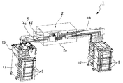
図1は本実施の形態に係るインクジェットプリンターのインク供給系の説明図である。図2はインク供給系の要部の斜視図である。図3は加圧ポンプの斜視図である。インクジェットプリンター1は、外部の機器から印刷データの供給を受けると、印刷位置を経由する紙搬送路に沿って記録紙を搬送し、印刷位置を通過する記録紙に対してインクジェットヘッド2により印刷を施すものである。
FIG. 1 is an explanatory diagram of an ink supply system of the ink jet printer according to the present embodiment. FIG. 2 is a perspective view of the main part of the ink supply system. FIG. 3 is a perspective view of the pressure pump. When the
図1に示すように、インクジェットプリンター1のインク供給系は、インクジェットプリンター1に着脱可能に装着されたインクカートリッジ3と、インクカートリッジ3に収納されているインクを、インク流路4を介してインクジェットヘッド2に供給するインク供給機構5を備えている。
As shown in FIG. 1, the ink supply system of the
インクカートリッジ3はインクを内包する可撓性のインクパック10と、このインクパック10を収容する剛性のケース11と、ケース11とインクパック10の間に形成された加圧室12を備えている。インク供給機構5は加圧ポンプ15と、加圧ポンプ15とインクパック10の加圧室12とを接続する空気圧送路16を備えている。インク供給機構5は、加圧ポンプ15によって空気圧送路16を介して加圧室12内に空気を送り込み、加圧室12内の空気圧によってインクパック10を押圧することにより、インクパック10内のインクをインク流路4の側に送り出す。
The
インクカートリッジ3がインクジェットプリンター1のカートリッジ装着部17(図2参照)に装着されると、インク流路4の上流端4a(インクジェットヘッド2とは反対側の端)がインクパック10に着脱可能に接続される。より詳細には、インク流路4の上流端4aには針4bが設けられており、インクカートリッジ3がカートリッジ装着部17に装着されると、ケース11およびインクパック10に設けられた針挿口を介して針4bがインクパック10に差し込まれ、インクパック10内のインクがインク流路4の側に流出可能となる。また、インクカートリッジ3がカートリッジ装着部17に装着されると、空気圧送路16の下流端16a(空気圧送路16の加圧ポンプ15とは反対側の端)が加圧室12に着脱可能に接続される。より詳細には、インクカートリッジ3がインクジェットプリンター1に装着されると、ケース11に設けられた加圧室12の空気導入口11aと空気圧送路16の下流端16aの開口と連通した状態が形成される。
When the
図2に示すように、本例のインクジェットプリンター1では、カートリッジ装着部17に6つのインクカートリッジ3が装着される。加圧ポンプ15と6つのインクカートリッジ3のそれぞれとを接続する空気圧送路16は平面基板18上に構成されている。インクジェットヘッド2と各インクカートリッジ3とを接続するインク流路4は平面基板18上に構成された第1インク流路部分4cと、インク流路4部分の下流端16aとインクジェットヘッド2の間を接続する可撓性の第2インク流路部分4dを備えている。各インクカートリッジ3は重力方向でインクジェットヘッド2よりも下方に位置している。インクジェットヘッド2はインクノズルのノズル面2aを下方に向けた状態で配置されている。
As shown in FIG. 2, in the
図3に示すように、加圧ポンプ15は、駆動源となるDCモーター20と、空気を加圧するためのジャバラポンプ部21と、ジャバラポンプ部21によって加圧された空気を空気圧送路16の側に噴出す空気供給口22(図1参照)を備えている。空気供給口22は空気圧送路16の上流端16bに接続されており、空気供給口22は空気圧送路16を介してインクカートリッジ3の加圧室12と連通している。
As shown in FIG. 3, the pressurizing
また、加圧ポンプ15は、ジャバラポンプ部21と空気供給口22とを連通させているポンプ内空気流路23の途中に、自己の加圧量を検出するための圧力センサー24とレギュレーター25を備えている。圧力センサー24とレギュレーター25とは、ポンプ内空気流路23の空気圧送方向の上流側から下流側に向かってこの順番で配置されている。さらに、加圧ポンプ15は、ジャバラポンプ部21の加圧動作の回数、すなわち、ジャバラポンプ部21が圧縮された回数を検出するためのポンプセンサー26を備えている。ポンプセンサー26は、例えば、ジャバラポンプ部21が圧縮される毎に操作されるスイッチである。
Further, the pressurizing
圧力センサー24は、図1に示すように、ジャバラポンプ部21から加圧室12に向かって圧送される空気を導入する空気導入室30と、空気導入室30の一つの壁面を構成するとともに空気導入室30内の圧力によって変位するダイヤフラム32と、ダイヤフラム32の変位を検出する光学センサーユニット33を備えている。
As shown in FIG. 1, the
ここで、ダイヤフラム32は、ダイヤフラム32に対向している空気導入室30の底面30aから離れる方向に膨らんで空気導入室30の容積を拡大させている外側位置32Aと、空気導入室30の底面30aに接近する方向に窪んで空気導入室30の容積を縮小させている内側位置32Bとの間を変位する。光学センサーユニット33は、ダイヤフラム32が外側位置32Aに配置された状態と内側位置32Bに配置された状態を検出する。光学センサーユニット33がダイヤフラム32の外側位置32Aへの配置を検出すると、圧力センサー24は、ジャバラポンプ部21による加圧量(加圧ポンプ15の加圧量)が第1設定加圧量P1となったことを示す第1信号を出力する。光学センサーユニット33がダイヤフラム32の内側位置32Bへの配置を検出すると、圧力センサー24は、ジャバラポンプ部21による加圧量(加圧ポンプ15の加圧量)が予め定めた第1基準加圧量Q1以下となったことを示す第2信号を出力する。第1基準加圧量Q1は第1設定加圧量P1よりも低い加圧量である。
Here, the
ここで、光学センサーユニット33としては、ダイヤフラム32の外面に取り付けた反射部材33aと、反射部材33aに対向する位置に配置された反射型フォトセンサー33bを備える構成のものを採用することができる。この場合、反射型フォトセンサー33bは反射部材33aに向かって検査光を照射するとともに、反射部材33aからの検査光の反射光を受光する。圧力センサー24は反射型フォトセンサー33bからの出力に基づいて反射型フォトセンサー33bと反射部材33aとの間の距離を取得することにより、ダイヤフラム32の位置(変位)を検出する。
Here, as the
レギュレーター25は、ポンプ内空気流路23の側壁部分に設けられた開口35と、開口35を空気流路の外側から封鎖する封鎖部材36と、封鎖部材36を開口35を封鎖する方向に所定の付勢力で付勢するコイルバネなどの付勢部材37を備えている。
The
レギュレーター25は、ジャバラポンプ部21による加圧量(加圧ポンプ15の加圧量)が、当該レギュレーター25の動作設定圧力以上となると動作して、その加圧量を低下させる。より詳細には、ジャバラポンプ部21による加圧量が動作設定圧力以上となると、付勢部材37の付勢力に抗して封鎖部材36が開口35を開く方向に移動して開口35から空気を流出させて、加圧ポンプ15の加圧量を低下させる。しかる後に、ジャバラポンプ部21による加圧量が動作設定圧力よりも低下すると、付勢部材37の付勢力によって封鎖部材36が開口35を閉じる方向に戻り、開口35を封鎖した状態となる。
The
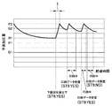
(制御系)
図4は、インクジェットプリンター1の制御系を示す概略ブロック図である。図5は加圧量変化情報を示すグラフである。図4に示すように、インクジェットプリンター1はCPUを備える制御部40を中心に構成されている。制御部40の入力側には、通信インターフェースを備える通信部41、加圧ポンプ15の圧力センサー24およびポンプセンサー26が接続されている。制御部40の出力側には記録紙を搬送するための紙送りモーター43、インクジェットヘッド2、加圧ポンプ15のDCモーター20が不図示のドライバーを介して接続されている。また、制御部40にはメモリー(記憶部)44が接続されている。通信部41は、外部の機器から印刷データを受信する。
(Control system)
FIG. 4 is a schematic block diagram illustrating a control system of the
制御部40は、受信した印刷データを印刷する印刷動作を司る印刷制御部50、インクジェットヘッド2によるインク使用量を取得するインク使用量取得部51、インクパック10内のインク残量を取得するインク残量取得部(インク残量監視部)52、加圧ポンプ15を駆動制御する加圧制御部53、タイマーを備える計測部54、加圧ポンプ15の加圧量を予測する加圧量予測部55を備えている。
The
印刷制御部50は、通信部41が印刷データを受信すると、紙送りモーター43を駆動して記録紙を印刷位置にセットする頭出しを行う。しかる後に、加圧ポンプ15の加圧量を監視して、加圧ポンプ15が基準加圧量に達している場合に、紙送りモーター43およびインクジェットヘッド2を駆動制御して印刷データの印刷を開始する。加圧ポンプ15の基準加圧量は、当該基準加圧量とインクジェットヘッド2のインクノズル開口に形成されるインクのメニスカス耐圧を合計した第1の圧力の方が、インクパック10の位置水頭、インクパック10の背圧、および、インク流路4の流路動圧とを合計した第2の圧力よりも大きくなるように設定されている。
When the
インク使用量取得部51は、インクジェットヘッド2から吐出されるインク滴のショット数を計数しており、このショット数に基づいてインクジェットヘッド2によるインク使用量を算出して取得する。
The ink usage
インク残量取得部(インク残量監視部)52は、インクパック10に内包されたインクの規定インク量からインクジェットヘッド2によるインク使用量を減算してインクパック内のインク残量を取得する。また、インク残量取得部52は、このインク残量が、予め設定した残量以下となる閾値に達したか否かを監視している。閾値は、インクパック内のインク残量がゼロに近くなると検出される。
The ink remaining amount acquisition unit (ink remaining amount monitoring unit) 52 subtracts the amount of ink used by the
加圧制御部53は、インク残量取得部52によってインクパック10内のインク残量が閾値に達したことが検出されていない場合に加圧ポンプ15を駆動制御する第1加圧制御部56と、インク残量取得部52により閾値に達したことが検出されている場合に、加圧ポンプ15を駆動制御する第2加圧制御部57を備えている。
The
第1加圧制御部56は、通信部41が印刷データを受信したときに圧力センサー24が第2信号を出力する状態となっていると、圧力センサー24から第1信号が出力されるまで加圧ポンプ15を駆動して当該加圧ポンプ15を停止する。すなわち、第1加圧制御部56は、印刷データの受信時点で加圧ポンプ15の加圧量が第1基準加圧量Q1以下となっている場合に、加圧ポンプ15を駆動して、その加圧量を第1設定加圧量P1とする。
If the
ここで、印刷制御部50はインクパック10内のインク残量が閾値に達したことが検出されていない場合(第1加圧制御部56によって加圧ポンプ15が駆動制御されている場合)には、印刷を開始する基準の基準加圧量を第1基準加圧量Q1としている。従って、通信部41が印刷データを受信した後に加圧ポンプ15が駆動されてその加圧力が第1設定加圧量P1に達すると、印刷制御部50は印刷データの印刷を開始する。
Here, when it is not detected that the ink remaining amount in the
第2加圧制御部57は、初期加圧部58、第1追い加圧部59および第2追い加圧部60を備えている。
The second
初期加圧部58は、インク残量取得部52によって閾値に達したことが検出されると、加圧ポンプ15を駆動してその加圧量を第2設定加圧量P2に到達させる初期加圧動作を行い、加圧ポンプ15を停止する。第2設定加圧量P2は、第1設定加圧量P1よりも高い値である。
When the
より具体的には、初期加圧部58は、インク残量取得部52によって閾値に達したことが検出されたときに圧力センサー24から第1信号が出力されている場合には、予め定めた所定回数だけジャバラポンプ部21を駆動して、加圧ポンプ15の加圧量を第2設定加圧量P2に到達させる。一方、インク残量取得部52によって閾値に達したことが検出されたときに、圧力センサー24から第1信号が出力されていない場合には、初期加圧部58は、圧力センサー24から第1信号が出力されるまでジャバラポンプ部21を駆動し、しかる後に、予め定めた所定回数だけジャバラポンプ部21を駆動して、加圧ポンプ15の加圧量を第2設定加圧量P2に到達させる。なお、本例のインクジェットプリンターは、加圧ポンプ15の加圧量が第2設定加圧量P2に到達したことを検出するセンサーを搭載していない。従って、初期加圧部58では、圧力センサー24から第1信号が出力された後にジャバラポンプ部21を所定回数駆動することによって、加圧ポンプ15の加圧量が第2設定加圧量P2に到達したものとみなしている。
More specifically, the
第1追い加圧部59は、加圧量予測部55が取得した予測加圧量が第1設定加圧量P1よりも低い下限加圧量R1以下となると、加圧ポンプ15を駆動して予測加圧量を第2設定加圧量P2に到達させる第1追い加圧動作を行う。ここで、下限加圧量R1は第1設定加圧量P1よりも高い値である。また、下限加圧量R1は、予測加圧量が下限加圧量R1となった加圧ポンプ15を駆動して第2設定加圧量P2に到達させるまでの駆動時間t(図8参照)が、印刷データを受信してからインクジェットヘッド2により印刷データの印刷が開始されるまでの印刷準備時間よりも短くなるように、設定されている。印刷準備時間は、例えば、通信部41が外部の機器から印刷データを受信した時点から、記録紙を印刷位置にセットする頭出しが完了するまでの時間である。
The first
第2追い加圧部60は、印刷データの受信時点で加圧量予測部55が取得した予測加圧量が第2設定加圧量P2よりも低く、下限加圧量R1よりも高い第2基準加圧量Q2以下となっている場合に、加圧ポンプ15を駆動して予測加圧量を第2設定加圧量P2に到達させる第2追い加圧動作を行う。
The second
ここで、印刷制御部50は、インクパック10内のインク残量が閾値に達したことが検出されている場合(第2加圧制御部57によって加圧ポンプ15が駆動制御されている場合)には、印刷を開始する基準の基準加圧量を第2基準加圧量Q2としている。従って、通信部41が印刷データを受信した後に加圧ポンプ15が駆動されてその予測加圧力が第2基準加圧量Q2を上回る第2設定加圧量P2に達すると、印刷制御部50は印刷データの印刷を開始する。
Here, the
加圧量予測部55は、加圧ポンプ15の加圧量を、メモリー44に記憶保持されている加圧量変化情報61、加圧ポンプ15の加圧停止時点の後のインク使用量、および、加圧ポンプ15の加圧動作(初期加圧動作、第1追い加圧動作、第2追い加圧動作)に基づいて一定間隔で算出して、取得している。
The pressurization
加圧量変化情報61は、加圧ポンプ15をその加圧量が第2設定加圧量P2となるまで駆動した後に加圧ポンプ15を停止し、加圧ポンプ15が停止した時点から減少する加圧ポンプ15の加圧量を実測し、実測の結果を加圧ポンプ15が停止した時点からの経過時間と加圧ポンプ15の加圧量の変化とを関係付けたものである。加圧量変化情報61をグラフで示した場合には、例えば、図5のように示される。本例では、経過時間と加圧ポンプ15の加圧量の変化(グラフの傾き)とをテーブルの形態でメモリー44に記憶保持している。
The pressurization
加圧ポンプ15の加圧停止時点の後のインク使用量とは、予測加圧量を第2設定加圧量P2に到達させて加圧ポンプ15を停止した後にインクジェットヘッド2により使用されたインク使用量である。インク使用量取得部51は、予測加圧量を第2設定加圧量P2に到達させた後に加圧ポンプ15が停止する毎に、それ以降のインク使用量を新たに取得しており、加圧量予測部55はインク使用量取得部51が取得している値を参照して取得することができる。
The amount of ink used after the pressurization stop of the
加圧ポンプ15の加圧動作とは、初期加圧動作、第1追い加圧動作および第2追い加圧動作のそれぞれの動作の間にジャバラポンプ部21が駆動(圧縮)された回数であり、加圧量予測部55は、ポンプセンサー26からの出力に基づいてこの値を取得することができる。
The pressurizing operation of the pressurizing
ここで、加圧ポンプ15の第2設定加圧量P2は、加圧ポンプ15に搭載されているレギュレーター25が動作する動作設定圧力をSP、前記レギュレーター25の動作が前記動作設定圧力に対してバラつく圧力範囲を±αとしたときに、以下の条件式(1)、(2)を満たしている。
P2>SP−α (1)
P2−β>SP−α (2)
Here, the second set pressurization amount P2 of the
P2> SP-α (1)
P2-β> SP-α (2)
一般的に、レギュレーター25を搭載する加圧ポンプ15はレギュレーター25を動作させない範囲で、その加圧量の上限値が設定される。すなわち、加圧ポンプ15の加圧量を設定する場合には、レギュレーター25の動作の誤差の範囲(動作設定圧力に対してバラつく圧力範囲)を考慮して、所望とする加圧量からこの誤差の範囲分を差し引いた値を設定加圧量とすることが行われる。これに対して、本例では、レギュレーター25が動作してもインクの供給動作に影響がないので、レギュレーター25の動作の誤差の範囲を考慮せず、条件式(1)を満たすように加圧ポンプ15の第2設定加圧量P2を設定している。これにより、レギュレーター25の動作の誤差の範囲を考慮した場合と比較して、第2設定加圧量P2が高い値となる。従って、レギュレーター25の動作の誤差の範囲を考慮した場合と比較して、インクパック10を高い圧力で付勢できる。
In general, an upper limit value of the pressurizing amount of the pressurizing
また、一般的に、レギュレーター25を搭載する加圧ポンプ15は、レギュレーター25を動作させないように、加圧ポンプ15の動作の誤差の範囲(加圧ポンプ15の加圧量が設定した加圧量に対してバラつく範囲)を考慮して、その加圧量の上限値が設定される。すなわち、加圧ポンプ15の加圧量を設定する場合には、所望とする加圧量からこの誤差の範囲を差し引いた値を設定加圧量とすることが行われる。これに対して、本例では、レギュレーター25が動作しても、インク供給動作に影響がないので、加圧ポンプ15の動作の誤差の範囲を考慮せずに、条件式(2)を満たすように、加圧ポンプ15の第2設定加圧量P2を設定している。これにより、加圧ポンプ15の動作の誤差の範囲を考慮した場合と比較して、第2設定加圧量P2が高い値となる。従って、レギュレーター25の動作の誤差の範囲を考慮した場合と比較して、インクパック10を高い圧力で付勢できる。ここで、インクパック10を高い圧力で付勢すれば、インク流路4に送り出されることなくインクパック10内に残留する残留インクを少なくすることができる。
In general, the pressurizing
(インク供給制御動作)
次に、図6乃至図8を参照してインク供給制御動作を説明する。図6はインク供給制御動作のフローチャートである。図7は閾値が検出されていない場合のインク供給動作時における加圧ポンプの加圧量の変化を示すグラフである。図8は閾値が検出されている場合のインク供給動作時における加圧ポンプの加圧量の変化を示すグラフである。
(Ink supply control operation)
Next, the ink supply control operation will be described with reference to FIGS. FIG. 6 is a flowchart of the ink supply control operation. FIG. 7 is a graph showing a change in the amount of pressurization of the pressurization pump during the ink supply operation when the threshold is not detected. FIG. 8 is a graph showing a change in the amount of pressurization of the pressurization pump during the ink supply operation when the threshold is detected.
図6に示すように、インクジェットプリンター1が動作すると、インク残量取得部52は、閾値に達しているインクパック10があるか否かを判定する(ステップST1)。ここで、いずれのインクパック10も閾値に達していない場合には、第1加圧制御部56が加圧ポンプ15の駆動制御を司る通常状態に移行するとともに、印刷データの供給を待つアイドル状態に移行する。
As shown in FIG. 6, when the
ここで、通信部41が外部の機器から印刷データの供給を受けると(ステップST2)、第1加圧制御部56は、加圧ポンプ15の加圧量が第1基準加圧量Q1以下となっているか否かを確認する(ステップST3)。すなわち、圧力センサー24から第2信号が出力されているか否かを確認する。
Here, when the
圧力センサー24から第2信号が出力されている場合、すなわち、加圧ポンプ15の加圧量が第1基準加圧量Q1以下となっている場合(図7の(ST3:YES)の場合)には、第1加圧制御部56は加圧ポンプ15を第1設定加圧量P1となるまで駆動し、しかる後に、加圧ポンプ15を停止する(ステップST4)。すなわち、第1加圧制御部56は圧力センサー24から第1信号が出力されるまで加圧ポンプ15を駆動して、加圧ポンプ15を停止する。これにより圧力センサー24からは第2信号が出力されなくなる。印刷制御部50は、第2信号が出力されなくなると加圧ポンプ15の加圧量が基準加圧量(第1基準加圧量Q1)を上回ったと判断して、印刷データの印刷を開始する(ステップST5)。
When the second signal is output from the
ステップST3において、加圧ポンプ15の加圧量が第1基準加圧量Q1を超えている場合(図7の(ST3:NO)の場合)には、圧力センサー24から第2信号が出力されていない。従って、印刷制御部50は、加圧ポンプ15の加圧量が基準加圧量(第1基準加圧量Q1)を上回っていると判断して、印刷データの印刷を開始する(ステップST5)。すなわち、第1加圧制御部56により加圧ポンプ15が駆動されることなく、印刷データの印刷が行われる(ステップST5)。
In step ST3, if the pressurization amount of the
次に、ステップST1において、インク残量取得部52によりインクパック10のインク残量が閾値に達したインクパック10があることが検出された場合には、加圧ポンプ15の駆動制御を第2加圧制御部57が司るニアエンド近傍検出状態に移行するとともに、印刷データの供給を待つアイドル状態に移行する。
Next, in step ST1, when the ink remaining
ここで、インクパック10のインク残量が閾値に達したインクパック10があることが検出されると、初期加圧部58が加圧ポンプ15を駆動して初期加圧動作を行ない加圧ポンプ15の加圧量を第2設定加圧量P2に到達させる。すなわち、閾値に達したインクパック10があることが検出された時点では、加圧ポンプ15の加圧量が第1設定加圧量P1よりも圧力の高い下限加圧量R1に達していることはないので(ステップST6)、初期加圧部58は加圧ポンプ15を駆動して、その加圧量を第2設定加圧量P2として当該加圧ポンプ15を停止させる(ステップST7)。
Here, when it is detected that there is an
その後に、通信部41が外部の機器から印刷データの供給を受けると(ステップST8)、第2加圧制御部57は、加圧ポンプ15の予測加圧量が第2基準加圧量Q2以下となっているか否かを確認する(ステップST9)。
Thereafter, when the
ステップST9において、予測加圧量が第2基準加圧量Q2以下となっている場合(図8の(ST9:YES)の場合)には、第2追い加圧部60は加圧ポンプ15を駆動して予測加圧量を第2設定加圧量P2に到達させる第2追い加圧動作を行う(ステップST10)。ステップST10において、加圧ポンプ15が停止すると、予測加圧量として第2設定加圧量P2が取得される。すなわち、予測加圧量は、印刷制御部50が印刷開始の基準としている基準加圧量(第2基準加圧量Q2)を上回る。従って、印刷制御部50は印刷データの印刷を開始する(ステップST5)。一方、ステップST9において、予測加圧量が第2基準加圧量Q2を超えている場合(図8の(ST9:NO)の場合)には、印刷制御部50は印刷データの印刷を開始する(ステップST5)。すなわち、第2加圧制御部57により加圧ポンプ15が駆動されることなく、印刷が行われる。
In step ST9, when the predicted pressurization amount is equal to or less than the second reference pressurization amount Q2 (in the case of (ST9: YES) in FIG. 8), the second
ここで、ステップST7において、加圧ポンプ15が停止すると、加圧量予測部55は一定間隔で加圧ポンプ15の加圧量を予測加圧量として取得する。そして、ステップST7以降に、印刷データの供給を受けていない場合には、加圧量予測部55が予測加圧量を取得する毎に、この予測加圧量と下限加圧量R1とが比較される(ステップST11、ステップST6)。
Here, when the
その後、ステップST6において、予測加圧量が下限加圧量R1以下となったことが検出された場合(図8の(ST6:YES)の場合)には、第1追い加圧部59は、加圧ポンプ15をその予想加圧量が第2基準加圧量Q2となるまで駆動する第1追い加圧動作を行う。これにより、加圧ポンプ15の加圧量が下限加圧量R1となることが回避される。
Thereafter, when it is detected in step ST6 that the predicted pressurization amount has become the lower limit pressurization amount R1 or less (in the case of (ST6: YES) in FIG. 8), the first additional pressurization unit 59 A first additional pressurizing operation is performed in which the
(作用効果)
本例によれば、インクパック10のインク残量が閾値に達して当該インクパック10の背圧が上昇する際に、加圧ポンプ15の加圧量を第1設定加圧量P1から第2設定加圧量P2に上昇させる。従って、インクパック10の背圧の上昇に拘わらず、インクパック10内のインクをインク流路4の側に送り出すことができる。よって、インク流路4に送り出されることなくインクパック10内に残留する残留インクを少なくすることができる。また、加圧ポンプ15を高圧で駆動するのは、インクパック10のインク残量が閾値に達した後の期間だけなので、加圧ポンプ15の駆動時間が長くなることを抑制することができ、加圧ポンプ15の寿命の短縮を抑制できる。
(Function and effect)
According to this example, when the ink remaining amount of the
また、本例では、レギュレーター25の動作の誤差の範囲および加圧ポンプ15の動作の誤差の範囲を考慮せずに、第2設定加圧量P2を設定している。この結果、第2設定加圧量P2を高い値とすることができるので、インクパック10を付勢する圧力が強くなり、残留インクをより少なくすることができる。
Further, in this example, the second set pressurization amount P2 is set without considering the error range of the
さらに、本例では、加圧ポンプ15の加圧量を予測加圧量として把握しているので、インクパック10のインク残量が閾値に達した後の加圧ポンプ15の駆動制御を新たな圧力センサー24を設けることなく行うことができる。従って、インクパック10のインク残量が閾値に達した後において、加圧ポンプ15の加圧量を高い値で維持することができる。また、本例では、予測加圧量を算出する際に実測結果から求めた加圧量変化情報61を利用しているので、予測加圧量を精度よく算出できる。
Further, in this example, since the pressurization amount of the
1・・インクジェットプリンター、2・・インクジェットヘッド、2a・・ノズル面、3・・インクカートリッジ、4・・インク流路、4a・・上流端、4b・・針、4c・・インク流路部分、4d・・インク流路部分、5・・インク供給機構、10・・インクパック、11・・ケース、11a・・空気導入口、12・・加圧室、15・・加圧ポンプ、16・・空気圧送路、16a・・下流端、16b・・上流端、17・・カートリッジ装着部、18・・平面基板、20・・DCモーター、21・・ジャバラポンプ部、22・・空気供給口、23・・ポンプ内空気流路、24・・圧力センサー、25・・レギュレーター、26・・ポンプセンサー、30・・空気導入室、30a・・底面、32・・ダイヤフラム、32A・・外側位置、32B・・内側位置、33・・光学センサーユニット、35・・開口、36・・封鎖部材、37・・付勢部材、40・・制御部、41・・通信部、43・・紙送りモーター、44・・メモリー(記憶部)、50・・印刷制御部、51・・インク使用量取得部、52・・インク残量取得部(インク残量監視部)、53・・加圧制御部、54・・計測部、55・・加圧量予測部、56・・第1加圧制御部、57・・第2加圧制御部、58・・初期加圧部、59・・第1追い加圧部、60・・第2追い加圧部、61・・加圧量変化情報、P1・・第1設定加圧量、P2・・第2設定加圧量、Q1・・第1基準加圧量、Q2・・第2基準加圧量、R1・・下限加圧量
1 .... Inkjet printer, 2 .... Inkjet head, 2a ..., Nozzle surface, 3 .... Ink cartridge, 4 .... Ink flow path, 4a ..., Upstream end, 4b ..., Needle, 4c ..., Ink flow path part, 4d. Ink flow path portion, 5 ... Ink supply mechanism, 10 ... Ink pack, 11 ... Case, 11a ... Air inlet, 12 .... Pressurizing chamber, 15 .... Pressure pump, 16 ... Pneumatic feed path, 16a ... downstream end, 16b ... upstream end, 17 ... cartridge mounting part, 18 ... flat substrate, 20 ... DC motor, 21 ... bellows pump part, 22 ... air supply port, 23 ..Air flow path in pump, 24..Pressure sensor, 25..Regulator, 26..Pump sensor, 30..Air introduction chamber, 30a..Bottom surface, 32..Diaphragm, 32A..Outside position, 32B -Inside position, 33-Optical sensor unit, 35-Opening, 36-Blocking member, 37-Biasing member, 40-Control unit, 41-Communication unit, 43-Paper feed motor, 44- · Memory (storage unit), 50 · · Print control unit, 51 · · Ink usage acquisition unit, 52 · · Ink remaining amount acquisition unit (ink remaining amount monitoring unit), 53 · · Pressure control unit, 54 · ·
Claims (10)
前記インクパックのインク残量が予め設定した残量以下となる閾値に達したか否かを監視し、
前記閾値に達したことが検出されていない場合には、前記加圧ポンプをその加圧量が予め設定した第1設定加圧量となるまで駆動し、
前記閾値に達したことが検出されている場合には、前記加圧ポンプをその加圧量が前記第1設定加圧量よりも高い第2設定加圧量となるまで駆動することを特徴とするインクジェットプリンターのインク供給制御方法。 In an ink supply control method for an ink jet printer, a flexible ink pack containing ink is pressurized with a pressure pump and the ink is supplied to an ink flow path communicating with an ink jet head.
Monitoring whether the ink remaining amount of the ink pack has reached a threshold value that is equal to or less than a preset remaining amount;
If it is not detected that the threshold value has been reached, the pressurizing pump is driven until the pressurizing amount reaches a preset first set pressurizing amount,
When it is detected that the threshold value has been reached, the pressurizing pump is driven until the pressurizing amount becomes a second set pressurizing amount higher than the first set pressurizing amount. Ink supply control method for inkjet printer.
前記加圧ポンプはレギュレーターを備えており、
前記加圧ポンプの前記第2設定加圧量をP2、前記加圧ポンプに搭載されているレギュレーターが動作する動作設定圧力をSP、前記レギュレーターの動作が前記動作設定圧力に対してバラつく圧力範囲を±αとしたときに、以下の条件式(1)を満たすことを特徴とするインクジェットプリンターのインク供給制御方法。
P2>SP−α (1) In claim 1,
The pressurizing pump includes a regulator;
The second set pressurization amount of the pressurization pump is P2, the operation set pressure at which the regulator mounted on the pressurization pump operates is SP, and the pressure range in which the operation of the regulator varies with respect to the operation set pressure An ink supply control method for an ink jet printer, wherein the following conditional expression (1) is satisfied:
P2> SP-α (1)
前記加圧ポンプの動作が目標とする目標加圧量に対してバラつく圧力範囲を±βとしたときに、以下の条件式(2)を満たすことを特徴とするインクジェットプリンターのインク供給制御方法。
P2−β>SP−α (2) In claim 2,
An ink supply control method for an ink jet printer, which satisfies the following conditional expression (2) when a pressure range in which the operation of the pressurizing pump varies with respect to a target pressurization amount is ± β: .
P2-β> SP-α (2)
予め、前記第2設定加圧量となるまで前記加圧ポンプを駆動した後に当該加圧ポンプを停止し、前記加圧ポンプが停止した時点からの時間経過に伴って減少する前記加圧ポンプの加圧量を実測し、実測結果を前記時間経過と前記加圧ポンプの加圧量の変化とを関係付けた加圧量変化情報として記憶保持しておき、
前記閾値に達したことが検出されると、前記加圧ポンプを駆動して当該加圧ポンプの加圧量を前記第2設定加圧量に到達させる加圧動作を行って前記加圧ポンプを停止し、
前記加圧ポンプを停止した加圧停止時点からの経過時間を計測するとともに、前記加圧停止時点からの前記インクジェットヘッドによるインク使用量を取得し、
前記加圧停止時点からの前記加圧ポンプの加圧量を、前記加圧量変化情報、前記加圧動作、前記時間経過およびインク使用量に基づいて所定の間隔で算出して予測加圧量として取得することを特徴とするインクジェットプリンターのインク供給制御方法。 In claim 2 or 3,
The pressure pump is stopped after the pressure pump is driven in advance until the second set pressure amount is reached, and the pressure pump decreases with the passage of time from the time when the pressure pump stops. Measure the amount of pressurization, and store the measured result as pressurization amount change information relating the time lapse and the change in the pressurization amount of the pressurization pump,
When it is detected that the threshold value has been reached, the pressurizing pump is driven to perform the pressurizing operation for causing the pressurizing amount of the pressurizing pump to reach the second set pressurizing amount. Stop,
While measuring the elapsed time from the pressurization stop time when the pressurization pump was stopped, obtaining the ink usage by the inkjet head from the pressurization stop time,
The pressurization amount of the pressurization pump from the pressurization stop time is calculated at a predetermined interval based on the pressurization amount change information, the pressurization operation, the elapsed time, and the ink use amount, and the predicted pressurization amount An ink supply control method for an ink jet printer, characterized in that:
前記予測加圧量が前記第1設定加圧量よりも高く前記第2設定加圧量よりも低い下限加圧量以下となると、前記加圧ポンプを駆動して前記予測加圧量を前記第2設定加圧量に到達させる第2の加圧動作を行うことを特徴とするインクジェットプリンターのインク供給制御方法。 In claim 4,
When the predicted pressurization amount falls below a lower limit pressurization amount that is higher than the first set pressurization amount and lower than the second set pressurization amount, the pressurization pump is driven to set the predicted pressurization amount to the first pressurization amount. 2. An ink supply control method for an ink jet printer, wherein a second pressurizing operation for reaching a set pressurizing amount is performed.
前記インクパックのインク残量が予め設定した残量以下となる閾値に達したか否かを監視するインク残量監視部と、
前記閾値に達したことが検出されていない場合には、前記加圧ポンプをその加圧量が予め設定した第1設定加圧量となるまで駆動する第1加圧制御部と、
前記閾値に達したことが検出されている場合には、前記加圧ポンプをその加圧量が前記第1設定加圧量よりも高い第2設定加圧量となるまで駆動する第2加圧制御部と、
を有することを特徴とするインクジェットプリンター。 In an ink jet printer comprising: a flexible ink pack containing ink; and a pressure pump that pressurizes the ink pack and supplies the ink to an ink flow path communicating with an ink jet head.
An ink remaining amount monitoring unit that monitors whether or not the ink remaining amount of the ink pack has reached a threshold value that is equal to or less than a preset remaining amount;
A first pressurization control unit that drives the pressurization pump until the pressurization amount reaches a preset first set pressurization amount when it is not detected that the threshold value has been reached;
When it is detected that the threshold value has been reached, the second pressurization is performed so that the pressurization pump is driven until the pressurization amount becomes a second set pressurization amount higher than the first set pressurization amount. A control unit;
An ink jet printer comprising:
前記加圧ポンプはレギュレーターを備えており、
前記加圧ポンプの前記第2設定加圧量をP2、前記加圧ポンプに搭載されているレギュレーターが動作する動作設定圧力をSP、前記レギュレーターの動作が前記動作設定圧力に対してバラつく圧力範囲を±αとしたときに、以下の条件式(1)を満たすことを特徴とするインクジェットプリンター。
P2>SP−α (1) In claim 6,
The pressurizing pump includes a regulator;
The second set pressurization amount of the pressurization pump is P2, the operation set pressure at which the regulator mounted on the pressurization pump operates is SP, and the pressure range in which the operation of the regulator varies with respect to the operation set pressure An inkjet printer characterized by satisfying the following conditional expression (1) where
P2> SP-α (1)
前記加圧ポンプの動作が目標とする目標加圧量に対してバラつく圧力範囲を±βとしたときに、以下の条件式(2)を満たすことを特徴とするインクジェットプリンター。
P2−β>SP−α (2) In claim 7,
An inkjet printer that satisfies the following conditional expression (2) when a pressure range in which the operation of the pressurizing pump varies with respect to a target pressurization amount is ± β.
P2-β> SP-α (2)
前記加圧ポンプをその加圧量が前記第2設定加圧量となるまで駆動した後に当該加圧ポンプを停止し、前記加圧ポンプが停止した時点から減少する前記加圧ポンプの加圧量を実測し、当該実測の結果を前記加圧ポンプが停止した時点からの経過時間と前記加圧ポンプの加圧量の変化とを関係付けた加圧量変化情報として記憶保持している記憶部とを有し、
前記第2加圧制御部は、
前記閾値に達したことが検出されると、前記加圧ポンプを駆動して当該加圧ポンプの加圧量を前記第2設定加圧量に到達させる加圧動作を行って前記加圧ポンプを停止する初期加圧部と、
前記加圧ポンプを停止した加圧停止時点からの経過時間を計測する計測部と、
前記加圧停止時点からの前記インクジェットヘッドによるインク使用量を取得するインク使用量取得部と、
前記加圧停止時点からの前記加圧ポンプの加圧量を、前記加圧量変化情報、前記加圧動作、前記時間経過およびインク使用量に基づいて所定の間隔で算出して予測加圧量として取得する加圧量予測部とを備えていることを特徴とするインクジェットプリンター。 In claim 7 or 8,
The pressurization amount of the pressurization pump is decreased after the pressurization pump is stopped after the pressurization pump is driven until the pressurization amount reaches the second set pressurization amount, and the pressurization pump is stopped. Is stored, and the measurement result is stored and held as pressurization amount change information in which the elapsed time from the time when the pressurization pump stops and the change in the pressurization amount of the pressurization pump are related to each other And
The second pressure controller is
When it is detected that the threshold value has been reached, the pressurizing pump is driven to perform the pressurizing operation for causing the pressurizing amount of the pressurizing pump to reach the second set pressurizing amount. An initial pressurizing section to stop;
A measuring unit for measuring an elapsed time from a pressurization stop time when the pressurization pump is stopped;
An ink usage amount acquisition unit for acquiring an ink usage amount by the inkjet head from the pressurization stop time;
The pressurization amount of the pressurization pump from the pressurization stop time is calculated at a predetermined interval based on the pressurization amount change information, the pressurization operation, the elapsed time, and the ink use amount, and the predicted pressurization amount An ink jet printer comprising: a pressurization amount prediction unit acquired as:
前記第2加圧制御部は、前記予測加圧量が前記第1設定加圧量よりも高く前記第2設定加圧量よりも低い下限加圧量以下となると、前記加圧ポンプを駆動して前記予測加圧量を前記第2設定加圧量に到達させる追い加圧動作を行う追い加圧部を備えていることを特徴とするインクジェットプリンター。 In claim 9,
The second pressurization control unit drives the pressurization pump when the predicted pressurization amount becomes equal to or lower than a lower limit pressurization amount that is higher than the first set pressurization amount and lower than the second set pressurization amount. An ink jet printer comprising: a repressurizing unit that performs a repressurizing operation for causing the predicted pressurization amount to reach the second set pressurization amount.
Priority Applications (5)
| Application Number | Priority Date | Filing Date | Title |
|---|---|---|---|
| JP2012225748A JP2014076596A (en) | 2012-10-11 | 2012-10-11 | Ink supply control method for ink jet printer and ink jet printer |
| CN201310466908.7A CN103722890B (en) | 2012-10-11 | 2013-10-09 | The providing ink control method of ink-jet printer and ink-jet printer |
| US14/051,961 US9033475B2 (en) | 2012-10-11 | 2013-10-11 | Ink supply control method for an inkjet printer, and an inkjet printer |
| US14/622,406 US9156274B2 (en) | 2012-10-11 | 2015-02-13 | Ink supply control method for an inkjet printer, and an inkjet printer |
| US14/850,463 US9452613B2 (en) | 2012-10-11 | 2015-09-10 | Ink supply control method for an inkjet printer, and an inkjet printer |
Applications Claiming Priority (1)
| Application Number | Priority Date | Filing Date | Title |
|---|---|---|---|
| JP2012225748A JP2014076596A (en) | 2012-10-11 | 2012-10-11 | Ink supply control method for ink jet printer and ink jet printer |
Publications (2)
| Publication Number | Publication Date |
|---|---|
| JP2014076596A true JP2014076596A (en) | 2014-05-01 |
| JP2014076596A5 JP2014076596A5 (en) | 2015-10-01 |
Family
ID=50782329
Family Applications (1)
| Application Number | Title | Priority Date | Filing Date |
|---|---|---|---|
| JP2012225748A Pending JP2014076596A (en) | 2012-10-11 | 2012-10-11 | Ink supply control method for ink jet printer and ink jet printer |
Country Status (1)
| Country | Link |
|---|---|
| JP (1) | JP2014076596A (en) |
Cited By (2)
| Publication number | Priority date | Publication date | Assignee | Title |
|---|---|---|---|---|
| JP2014076630A (en) * | 2012-10-12 | 2014-05-01 | Seiko Epson Corp | Ink supply control method for ink jet printer and ink jet printer |
| US20170008293A1 (en) * | 2015-07-06 | 2017-01-12 | Seiko Epson Corporation | Liquid ejecting apparatus and liquid supply method |
Citations (7)
| Publication number | Priority date | Publication date | Assignee | Title |
|---|---|---|---|---|
| JPH10128993A (en) * | 1996-10-24 | 1998-05-19 | Hewlett Packard Co <Hp> | Ink distributing system |
| JP2003300331A (en) * | 2002-04-10 | 2003-10-21 | Matsushita Electric Ind Co Ltd | Ink jet recording apparatus |
| JP2006069066A (en) * | 2004-09-02 | 2006-03-16 | Seiko Epson Corp | Pressure regulating method, pressure regulating unit and liquid ejector |
| JP2006192785A (en) * | 2005-01-14 | 2006-07-27 | Sharp Corp | Fluid ejector, inkjet printer, and control method of fluid ejector |
| JP2008195012A (en) * | 2007-02-15 | 2008-08-28 | Seiko Epson Corp | Fluid injection apparatus and fluid supply method in fluid injection apparatus |
| JP2008229953A (en) * | 2007-03-19 | 2008-10-02 | Seiko Epson Corp | Fluid ejector and ejection method |
| JP2009257339A (en) * | 2004-04-09 | 2009-11-05 | Seiko Epson Corp | Pressurizing pump device, liquid injection device and pressurization release method for pressurized fluid |
-
2012
- 2012-10-11 JP JP2012225748A patent/JP2014076596A/en active Pending
Patent Citations (7)
| Publication number | Priority date | Publication date | Assignee | Title |
|---|---|---|---|---|
| JPH10128993A (en) * | 1996-10-24 | 1998-05-19 | Hewlett Packard Co <Hp> | Ink distributing system |
| JP2003300331A (en) * | 2002-04-10 | 2003-10-21 | Matsushita Electric Ind Co Ltd | Ink jet recording apparatus |
| JP2009257339A (en) * | 2004-04-09 | 2009-11-05 | Seiko Epson Corp | Pressurizing pump device, liquid injection device and pressurization release method for pressurized fluid |
| JP2006069066A (en) * | 2004-09-02 | 2006-03-16 | Seiko Epson Corp | Pressure regulating method, pressure regulating unit and liquid ejector |
| JP2006192785A (en) * | 2005-01-14 | 2006-07-27 | Sharp Corp | Fluid ejector, inkjet printer, and control method of fluid ejector |
| JP2008195012A (en) * | 2007-02-15 | 2008-08-28 | Seiko Epson Corp | Fluid injection apparatus and fluid supply method in fluid injection apparatus |
| JP2008229953A (en) * | 2007-03-19 | 2008-10-02 | Seiko Epson Corp | Fluid ejector and ejection method |
Cited By (4)
| Publication number | Priority date | Publication date | Assignee | Title |
|---|---|---|---|---|
| JP2014076630A (en) * | 2012-10-12 | 2014-05-01 | Seiko Epson Corp | Ink supply control method for ink jet printer and ink jet printer |
| US20170008293A1 (en) * | 2015-07-06 | 2017-01-12 | Seiko Epson Corporation | Liquid ejecting apparatus and liquid supply method |
| JP2017013453A (en) * | 2015-07-06 | 2017-01-19 | セイコーエプソン株式会社 | Liquid jetting device and liquid supply method |
| US9956784B2 (en) * | 2015-07-06 | 2018-05-01 | Seiko Epson Corporation | Liquid ejecting apparatus and liquid supply method |
Similar Documents
| Publication | Publication Date | Title |
|---|---|---|
| US9033475B2 (en) | Ink supply control method for an inkjet printer, and an inkjet printer | |
| JP4729978B2 (en) | Control method for liquid ejection device and liquid ejection device | |
| JP4910351B2 (en) | Inkjet recording device | |
| JP5504700B2 (en) | Liquid ejection device | |
| US9757952B2 (en) | Control method of a printing device, and a printing device | |
| JP2014076596A (en) | Ink supply control method for ink jet printer and ink jet printer | |
| JP2007076363A (en) | Liquid container and liquid ejection device | |
| JP5857773B2 (en) | Liquid ejector | |
| JP6044252B2 (en) | Ink supply control method for inkjet printer and inkjet printer | |
| JP2013193246A (en) | Inkjet recording device | |
| US20080303848A1 (en) | Liquid-droplet ejecting apparatus | |
| JP4107257B2 (en) | Liquid ejecting apparatus and liquid remaining amount calculating method | |
| JP2006021380A (en) | Inkjet printer | |
| JP2007245701A (en) | Liquid cartridge and liquid injection control method | |
| JP2011088374A (en) | Stop control method of carriage during liquid supply | |
| JP2018103592A (en) | Image recording device | |
| JP2012201064A (en) | Method for detecting liquid remaining amount shortage, liquid supply device, and liquid ejection apparatus | |
| JP2010069845A (en) | Liquid feeding apparatus, printer, and controlling method for liquid feeding apparatus | |
| JP2007118208A (en) | Liquid ejector | |
| JP7463932B2 (en) | Liquid ejection device | |
| JP2010111117A (en) | Liquid supply device and printing apparatus including the same | |
| JP5791250B2 (en) | Recording device | |
| JP5190783B2 (en) | Ink jet recording apparatus, air leak detection method and program | |
| JP2006231528A (en) | Liquid storage body and liquid jet apparatus | |
| JP5448041B2 (en) | Ink end detection apparatus and ink jet recording apparatus |
Legal Events
| Date | Code | Title | Description |
|---|---|---|---|
| RD04 | Notification of resignation of power of attorney |
Free format text: JAPANESE INTERMEDIATE CODE: A7424 Effective date: 20150108 |
|
| A521 | Written amendment |
Free format text: JAPANESE INTERMEDIATE CODE: A523 Effective date: 20150817 |
|
| A621 | Written request for application examination |
Free format text: JAPANESE INTERMEDIATE CODE: A621 Effective date: 20150817 |
|
| A977 | Report on retrieval |
Free format text: JAPANESE INTERMEDIATE CODE: A971007 Effective date: 20160516 |
|
| A131 | Notification of reasons for refusal |
Free format text: JAPANESE INTERMEDIATE CODE: A131 Effective date: 20160524 |
|
| RD04 | Notification of resignation of power of attorney |
Free format text: JAPANESE INTERMEDIATE CODE: A7424 Effective date: 20160610 |
|
| A521 | Written amendment |
Free format text: JAPANESE INTERMEDIATE CODE: A523 Effective date: 20160624 |
|
| RD03 | Notification of appointment of power of attorney |
Free format text: JAPANESE INTERMEDIATE CODE: A7423 Effective date: 20160624 |
|
| A02 | Decision of refusal |
Free format text: JAPANESE INTERMEDIATE CODE: A02 Effective date: 20161004 |