JP2014046867A - Input device - Google Patents
Input device Download PDFInfo
- Publication number
- JP2014046867A JP2014046867A JP2012192570A JP2012192570A JP2014046867A JP 2014046867 A JP2014046867 A JP 2014046867A JP 2012192570 A JP2012192570 A JP 2012192570A JP 2012192570 A JP2012192570 A JP 2012192570A JP 2014046867 A JP2014046867 A JP 2014046867A
- Authority
- JP
- Japan
- Prior art keywords
- input unit
- unit
- display
- input
- change
- Prior art date
- Legal status (The legal status is an assumption and is not a legal conclusion. Google has not performed a legal analysis and makes no representation as to the accuracy of the status listed.)
- Pending
Links
Images

Classifications
-
- G—PHYSICS
- G06—COMPUTING OR CALCULATING; COUNTING
- G06F—ELECTRIC DIGITAL DATA PROCESSING
- G06F3/00—Input arrangements for transferring data to be processed into a form capable of being handled by the computer; Output arrangements for transferring data from processing unit to output unit, e.g. interface arrangements
- G06F3/01—Input arrangements or combined input and output arrangements for interaction between user and computer
- G06F3/03—Arrangements for converting the position or the displacement of a member into a coded form
- G06F3/033—Pointing devices displaced or positioned by the user, e.g. mice, trackballs, pens or joysticks; Accessories therefor
- G06F3/0354—Pointing devices displaced or positioned by the user, e.g. mice, trackballs, pens or joysticks; Accessories therefor with detection of two-dimensional [2D] relative movements between the device, or an operating part thereof, and a plane or surface, e.g. 2D mice, trackballs, pens or pucks
- G06F3/03547—Touch pads, in which fingers can move on a surface
-
- G—PHYSICS
- G06—COMPUTING OR CALCULATING; COUNTING
- G06F—ELECTRIC DIGITAL DATA PROCESSING
- G06F3/00—Input arrangements for transferring data to be processed into a form capable of being handled by the computer; Output arrangements for transferring data from processing unit to output unit, e.g. interface arrangements
- G06F3/01—Input arrangements or combined input and output arrangements for interaction between user and computer
- G06F3/016—Input arrangements with force or tactile feedback as computer generated output to the user
-
- G—PHYSICS
- G06—COMPUTING OR CALCULATING; COUNTING
- G06F—ELECTRIC DIGITAL DATA PROCESSING
- G06F2203/00—Indexing scheme relating to G06F3/00 - G06F3/048
- G06F2203/01—Indexing scheme relating to G06F3/01
- G06F2203/014—Force feedback applied to GUI
Landscapes
- Engineering & Computer Science (AREA)
- General Engineering & Computer Science (AREA)
- Theoretical Computer Science (AREA)
- Human Computer Interaction (AREA)
- Physics & Mathematics (AREA)
- General Physics & Mathematics (AREA)
- User Interface Of Digital Computer (AREA)
- Fittings On The Vehicle Exterior For Carrying Loads, And Devices For Holding Or Mounting Articles (AREA)
- Position Input By Displaying (AREA)
Abstract
【課題】例えば、表示に対して適切な操作を行うことを可能とする。
【解決手段】入力装置は、例えば、車両のステアリングに配置され、第1の面および前記第1の面と対向する第2の面を有するステアリングパッドと、前記ステアリングパッドの前記第1の面に配設され、表示部における表示態様の第1の変更を発生する操作を受け付ける第1の入力部と、前記ステアリングパッドの前記第2の面に配設され、前記表示部における表示態様の第2の変更を発生する操作を受け付ける第2の入力部とを有する。
【選択図】図5For example, it is possible to perform an appropriate operation for display.
An input device is disposed on a steering wheel of a vehicle, for example, and has a first surface and a steering pad having a second surface facing the first surface, and the first surface of the steering pad. A first input unit that receives an operation for generating a first change in the display mode of the display unit; and a second input unit that is disposed on the second surface of the steering pad and that is a second display mode of the display unit. And a second input unit that receives an operation for generating the change.
[Selection] Figure 5
Description
本技術は、入力装置に関する。 The present technology relates to an input device.
自動車が有する様々な機能(例えば、オーディオ再生機能やカーナビゲーション機能)を実行するための操作を、ドライバが視線を移動することなく行うための技術が提案されている。ドライバが視線を移動することなく行う操作は、ブラインド操作などと称される。下記特許文献1には、ブラインド操作を可能とするためのポインティングデバイスが記載されている。特許文献1に記載の技術は、単一のポンティングデバイスにドライバが指を接触させ、指を上下方向に移動させることにより、表示部に表示されるカーソルが上下方向に移動するものである。
Techniques have been proposed for a driver to perform operations for executing various functions (for example, an audio playback function and a car navigation function) possessed by an automobile without moving the line of sight. The operation performed by the driver without moving the line of sight is referred to as a blind operation.
近年、自動車内における表示部の大型化が進み、表示部に表示されるアイコンの数が増加する傾向にある。表示部には、複数のアイコンが縦横に表示される場合もある。特許文献1に記載の技術は、単一のポインティングデバイスを使用して、カーソルを上下方向のみに移動させることしかできない。このため、アイコンを選択するためのカーソルを適切な方向に移動させることができない、という問題があった。
In recent years, the size of a display unit in an automobile has increased, and the number of icons displayed on the display unit tends to increase. A plurality of icons may be displayed vertically and horizontally on the display unit. The technique described in
したがって、本技術の目的の一つは、表示に対して適切な操作を行うことができる入力装置を提供することにある。 Therefore, one of the objects of the present technology is to provide an input device that can perform an appropriate operation for display.
上述した課題を解決するために、本技術は、例えば、
車両のステアリングに配置され、第1の面および第1の面と対向する第2の面を有するステアリングパッドと、
ステアリングパッドの第1の面に配設され、表示部における表示態様の第1の変更を発生する操作を受け付ける第1の入力部と、
ステアリングパッドの第2の面に配設され、表示部における表示態様の第2の変更を発生する操作を受け付ける第2の入力部と
を有する入力装置である。
In order to solve the above-described problem, the present technology, for example,
A steering pad disposed on the steering of the vehicle and having a first surface and a second surface facing the first surface;
A first input unit that is disposed on the first surface of the steering pad and receives an operation for generating a first change in a display mode in the display unit;
And a second input unit that receives an operation for generating a second change in the display mode of the display unit, which is disposed on the second surface of the steering pad.
少なくとも一つの実施形態によれば、表示に対して適切な操作を行うことができる。 According to at least one embodiment, an appropriate operation can be performed on the display.
以下、本技術の実施形態について図面を参照しながら説明する。なお、説明は、以下の順序で行う。
<1.第1の実施形態>
<2.第2の実施形態>
<3.変形例>
なお、以下に説明する実施形態等は本技術の好適な具体例であり、本技術の内容がこれらの実施形態等に限定されるものではない。
Hereinafter, embodiments of the present technology will be described with reference to the drawings. The description will be given in the following order.
<1. First Embodiment>
<2. Second Embodiment>
<3. Modification>
The embodiments described below are suitable specific examples of the present technology, and the contents of the present technology are not limited to these embodiments.
<1.第1の実施形態>
「自動車の車内の一例」
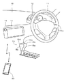
本技術の入力装置は、例えば、自動車のステアリングホイールに適用することができる。図1は、自動車の車内の一例を示す。自動車の車内のフロントガラスの下に、ダッシュボード(ダッシュパネルやインストルメントパネルなどと称されることがある)10が配設されている。ダッシュボード10における運転席の正面には、ステアリングホイール11が取り付けられるとともに、計器類12が配設されている。計器類12は、例えば、スピードメータ、タコメータ、燃料計などである。ステアリングホイール11の詳細については後述するが、ステアリングホイール11の例えばスポーク部に、第1入力部110aが配設されている。
<1. First Embodiment>
"An example in a car"
The input device of the present technology can be applied to a steering wheel of an automobile, for example. FIG. 1 shows an example in a car. A dashboard (sometimes referred to as a dash panel or an instrument panel) 10 is disposed under a windshield inside a car. A
ダッシュボード10の略中央には、表示部13が配設されている。表示部13は、例えば、LCD(Liquid Crystal Display)や有機EL(Electroluminescence)などの表示パネルである。表示部13には、メニュー画面やエアーコンディショナの調整のための画面、オーディオの再生に関する操作を行う画面、ナビゲーション機能に基づく地図などが表示される。
A
表示部13の周囲には、操作部14が設けられている。操作部14は、ダッシュボードなどに配設されるボタンやスイッチなどを総称したものである。なお、上述した表示部13がタッチスクリーンとして構成され、表示部13が操作部として機能してもよい。
An
運転席と助手席との間には、自動車の直進方向および後退方向(適宜、進行方向と総称する)に沿う方向に移動可能なシフトレバー15が配設されている。シフトレバー15は、自動車の進行方向に延在する、上面15aと、右側面15bと、左側面15cとを有する。さらに、自動車の進行方向と略直交する2面を有する。ダッシュボード側の面を前面15dと称し、他方の面を後面15eと称する。なお、シフトレバー15は、ステアリングホイール11の近傍に配設される、いわゆるコラムシフトレバーでもよい。
Between the driver's seat and the passenger seat, there is disposed a
ダッシュボード10の内部には、各種の制御を行う車載装置が収納されている。車載装置は、ステアリングホイール11と電気的に接続される。車載装置は、例えば、表示部13に対する表示制御や、操作部14、第1入力部110a、後述する第2入力部に対する操作に応じた処理を実行する。車載装置の構成については後述する。
An in-vehicle device that performs various controls is housed inside the
なお、車載装置が、例えばドライバが有する携帯端末20と通信を行うようにしてもよい。車載装置と携帯端末20との間で通信が行われることにより、それぞれの機器が有するデータの送受信が可能となる。例えば、携帯端末20から車載装置に対して表示データが送信されることにより、携帯端末20のメニュー画面を表示部13に表示させることができる。また、例えば、車載装置から携帯端末20に対して操作情報が送信されることにより、車載装置に対する操作に対応した携帯端末20の機能を実行できる。
Note that the in-vehicle device may communicate with the
なお、図示はしていないが、例えば、ステアリングホイール11の近傍には、ターンシグナルスイッチレバーやライトスイッチ等が設けられる。図1により図示される構成とは異なる構成が追加されたり、図示された構成の一部が削除されてもよい。さらに、各構成が配設される位置や各構成の形状は、適宜、変更できる。
Although not shown, for example, a turn signal switch lever or a light switch is provided in the vicinity of the
「ステアリングホイールの構成」
次に、ステアリングホイールの構成の一例について説明する。なお、以下の説明において左右上下等の方向を規定する表現を用いるが、これらは図面に向かう方向を基準にしている。方向を規定する表現は説明の便宜のためのものであり、本技術の内容が、当該方向に限定されるものではない。
"Structure of steering wheel"
Next, an example of the configuration of the steering wheel will be described. In the following description, expressions defining directions such as left, right, up and down are used, but these are based on the direction toward the drawing. The expression defining the direction is for convenience of explanation, and the content of the present technology is not limited to the direction.
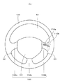
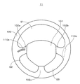
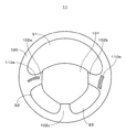
図2は、ステアリングホイール11の正面図である。ステアリングホイール11は、略リング状のホイール部100を有する。ホイール部100の内部の空間には、例えば、略五角形状のセンターパッド101が配されている。センターパッド101の内部には例えば、エアバッグが収納される。
FIG. 2 is a front view of the
センターパッド101の左右にスポーク部102aおよびスポーク部102bがそれぞれ配置され、センターパッド101の下部にスポーク部102cが配置される。個々のスポーク部を区別する必要がない場合は、スポーク部102と適宜、称する。
A spoke
スポーク部102a、スポーク部102bおよびスポーク部102cにより、ホイール部100とセンターパッド101とが連結される。すなわち、ステアリングホイール11は、ホイール部100と、センターパッド101と、スポーク部102とが一体的に構成されたものである。
The
例えば、センターパッド101とスポーク部102とにより、ステアリングパッド105が形成される。ステアリングパッド105は、ホイール部100の内部に配されるものであればよく、その名称は問わない。
For example, the
ホイール部100とセンターパッド101との間における空間が、スポーク部102aおよびスポーク部102bにより区画され、略半円状の空間S1が形成される。ホイール部100とセンターパッド101との間における空間が、スポーク部102aおよびスポーク部102cにより区画され、空間S2が形成される。ホイール部100とセンターパッド101との間における空間が、スポーク部102bおよびスポーク部102cにより区画され、空間S3が形成される。
A space between the
ステアリングパッド105における、例えば、スポーク部102bの第1の面に第1入力部110aが設けられる。スポーク部102bの第1の面とは、例えば、運転席に着座したドライバと略対向する面である。
In the
第1入力部110aは、例えば、感圧式のタッチパッドとして構成される。第1入力部110aの形状は、例えば、水平方向(左右方向)に延びる帯状をなし、その一部または全部が湾曲している。例えば、第1入力部110aは、アーチ状または片持ち梁状に湾曲する。第1入力部110aの全体の形状が直線状とされてもよい。図2では、第1入力部110aに対して、ハッチングが付されている。
The
ステアリングパッド105における、例えば、スポーク部102bの第2の面には、第2入力部110bが設けられる。スポーク部102bの第2の面とは、例えば、第1の面とは裏側(反対側)の面である。
In the
第2入力部110bは、例えば、感圧式のタッチパッドとして構成される。第2入力部110bの形状は、例えば、垂直方向(上下方向)に延びる帯状をなし、その一部または全部が湾曲している。例えば、第2入力部110bは、アーチ状または片持ち梁状に湾曲する。第2入力部110bの全体の形状が直線状とされてもよい。第2入力部110bは表側からは見えないため、図2では、第2入力部110bが点線により示されている。
The
図3は、ステアリングホイール11の背面図である。ステアリングパッド105のスポーク部102bの第2の面に、第2入力部110bが設けられる。図3では、第2入力部110bに対してハッチングが付され、第1入力部110aが点線により示されている。第1入力部110aおよび第2入力部110bは、例えば、それぞれの射影像が略直交する位置に配設される。なお、以下に説明において、第1入力部110aおよび第2入力部110bを区別する必要がない場合は、入力部110と適宜、称する。
FIG. 3 is a rear view of the
ステアリングホイールやステアリングパッドの形状は適宜、変更できる。図示しない構成が追加されてもよい。例えば、スポーク部にホーンボタンが配設されてもよい。さらに、スポーク部に「決定ボタン」や「戻るボタン」などのハードスイッチが配設されてもよい。「決定ボタン」は、例えば、表示部に表示されるアイコンの選択を確定するためのボタンである。「戻るボタン」は、表示部の画面を一つ前の画面に戻すためのボタンである。 The shape of the steering wheel and steering pad can be changed as appropriate. A configuration (not shown) may be added. For example, a horn button may be provided in the spoke part. Furthermore, hard switches such as a “decision button” and a “return button” may be arranged in the spoke portion. The “decision button” is, for example, a button for confirming selection of an icon displayed on the display unit. The “return button” is a button for returning the screen of the display unit to the previous screen.
入力部110は、ホイール部100の所定箇所が把持される際に、異なる指(例えば、親指と人差し指)で操作可能な範囲に配設されることが好ましい。ホイール部100の把持される箇所はドライバにより若干、異なるものの、大幅に異なることはない。さらに、ドライバの指の長さが人により大幅に異なることは稀であるため、入力部110が配設される範囲を適切に設定することができる。
The input unit 110 is preferably disposed in a range that can be operated with different fingers (for example, a thumb and an index finger) when a predetermined portion of the
「第1入力部および第2入力部に対する操作」
第1入力部110aおよび第2入力部110bに対する操作の一例について説明する。第1入力部110aおよび第2入力部110bに対する操作は、例えば、走行(信号等による一時的な停止を含む)中に、ドライバの右手を使用してなされる。
"Operations on the first input unit and the second input unit"
An example of an operation on the
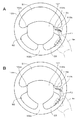
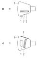
図4Aは、第1入力部110aに対する操作の一例を示す。ドライバの右手RHによりホイール部100の所定箇所が把持される。例えば、右手RHの親指F1以外の4本の指を空間S3に通すようにして、ホイール部100の所定位置が把持される。そして、親指F1の指先(適宜、親指と略称する)が第1入力部110aの操作面に接触され、第1入力部110aの操作面上で親指F1を使用した操作が行われる。
FIG. 4A shows an example of an operation on the
第1入力部110aは、例えば、以下の操作を受け付ける。
For example, the
(1)第1入力部110aの所定箇所に親指F1を接触させ、その位置から親指F1を接触させつつ、親指F1を左方向または右方向に移動するなぞる操作(以下、スライド操作と称する)
(1) An operation of bringing the thumb F1 into contact with a predetermined portion of the
(2)第1入力部110aを押圧(加圧)する操作(以下、押し込み操作と称する。)
例えば、1秒程度、第1入力部110aが押し込まれる。なお、第1入力部110aのいずれの箇所においても、押し込み操作が検出できるように構成される。したがって、ドライバは、第1入力部110aの任意の位置を押し込むことにより押し込み操作を行うことができる。なお、以下の説明では、閾値以上の押圧力による操作を「押圧」と称し、閾値より小さい押圧力による操作を「接触」と称し、区別する。
(2) An operation of pressing (pressing) the
For example, the
(3)第1入力部110aに対して、押し込み操作およびスライド操作を連続的に行う操作(以下、押し込みスライド操作と称する)
なお、始めに、押し込み操作による押圧を行えば、スライド操作において押し込み操作の押圧力を維持する必要はない。
(3) An operation of continuously performing a push-in operation and a slide operation on the
First, if a pressing operation is performed, it is not necessary to maintain the pressing force of the pressing operation in the sliding operation.
(4)第1入力部110aに対する押し込み操作を、所定時間以上、継続する操作(以下、押し込み長押し操作と称する)
なお、所定時間は、例えば、2秒程度に設定される。
(4) An operation of continuing the pushing operation with respect to the
The predetermined time is set to about 2 seconds, for example.
なお、ホイール部100を把持した状態で親指F1を水平方向に動かす際に、親指F1を直線状に移動することは困難である。しかしながら、本技術では、一例として、第1入力部110aの一部または全部を湾曲させ、親指F1を容易に移動できる方向に第1入力部110aを配設する。このため、第1入力部110aに対して、スライド操作または押し込みスライド操作を行う際の操作性が向上する。
It is difficult to move the thumb F1 in a straight line when moving the thumb F1 in the horizontal direction while holding the
さらに、第1入力部110aが一定の幅を有する帯状をなすため、例えば、ドライバ毎の親指F1全体の長さが相違する場合でも、第1入力部110aを確実に触れることができる。
Furthermore, since the
図4Bは、第2入力部110bに対する操作の一例を示す。ドライバの右手RHによりホイール部100の所定箇所が把持される。例えば、人差し指F2以外の4本の指により、ホイール部100の所定位置が把持される。そして、人差し指F2の指先(適宜、人差し指と略称する)が第2入力部110bの表面に接触され、第2入力部110bの表面上で人差し指F2を使用した操作が行われる。
FIG. 4B shows an example of an operation on the
第2入力部110bは、第1入力部110aに対する操作と同様の操作を受け付ける。
The
(1)第2入力部110bの所定箇所に人差し指F2を接触させ、その位置から人差し指F2を接触させつつ、人差し指F2を上方向または下方向に移動するなぞる操作(以下、スライド操作と称する)
(1) A tracing operation (hereinafter referred to as a sliding operation) in which the index finger F2 is brought into contact with a predetermined portion of the
(2)第2入力部110bを押圧する操作(以下、押し込み操作と称する。)
例えば、1秒程度、第2入力部110bが押し込まれる。なお、第2入力部110bのいずれの箇所においても、押し込み操作が検出できるように構成される。したがって、ドライバは、第2入力部110bの任意の位置を押し込むことにより押し込み操作を行うことができる。
(2) An operation of pressing the
For example, the
(3)第2入力部110bに対して、押し込み操作およびスライド操作を連続的に行う操作(以下、押し込みスライド操作と称する)
なお、始めに、押し込み操作による押圧を行えば、スライド操作において押し込み操作の押圧力を維持する必要はない。
(3) An operation of continuously performing a push operation and a slide operation on the
First, if a pressing operation is performed, it is not necessary to maintain the pressing force of the pressing operation in the sliding operation.
(4)第2入力部110bに対する押し込み操作を、所定時間以上、継続する操作(以下、押し込み長押し操作と称する)
なお、所定時間は、例えば、2秒程度に設定される。
(4) An operation of continuing the pushing operation on the
The predetermined time is set to about 2 seconds, for example.
なお、ホイール部100を把持した状態で人差し指F2を垂直方向に動かす際に、人差し指F2を直線状に移動することは困難である。しかしながら、本技術では、一例として、第2入力部110bの一部または全部を湾曲させ、人差し指F2を容易に移動できる方向に沿うように第2入力部110bを配設する。このため、第2入力部110bに対して、スライド操作または押し込みスライド操作を行う際の操作性が向上する。
When the index finger F2 is moved in the vertical direction while holding the
さらに、第2入力部110bが一定の幅を有する帯状をなすため、例えば、ドライバ毎の人差し指F2の長さが相違する場合でも、第2入力部110bを確実に触れることができる。なお、第2入力部110bに対する操作は、人差し指に限らず、中指を使用してなされてもよい。
Furthermore, since the
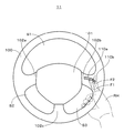
図5に示すように、例えば、親指F1と人差し指F2とにより、第1入力部110aおよび第2入力部110bに対する操作を連続的に行うようにしてもよい。例えば、親指F1を使用して第1入力部110aに対するスライド操作を行い、その後に、人差し指F2を使用して第2入力部110bに対するスライド操作を連続的に行うようにしてもよい。この場合でも、ホイール部100が3本の指と手のひらとにより把持されるため、ステアリングホイール11の操作性を損なうことはない。さらに、ドライバは、ホイール部100を把持しつつ入力部110に対する操作を行うことができるため、操作を行う際に視線を動かす必要がない。
As shown in FIG. 5, for example, the
なお、第1入力部110aが配設される第1の面および第2入力部110bが配設される第2の面の位置関係は、表裏の関係に限定されない。第1の面と第2の面とが対向すればよい。対向とは、必ずしも互いに向きあう関係に限定されない。所定の状態において異なる指(例えば、親指と人差し指)で操作可能な領域を有し、互いに近傍に配される2面であればよい。第2の面がステアリングパッド105の側面のように、第2の面が第1の面と略直交する面でもよい。
The positional relationship between the first surface on which the
さらに、入力部110に対する操作に応じて、ドライバに対する報知(フィードバック)動作が行われてもよい。ドライバに対して、例えば、音や表示などによる報知がなされる。しかしながら、操作の際には入力部110に指が触れられることから、好ましくは、操作がなされた入力部110が振動することにより報知がなされる。報知動作が行われることにより、ドライバは、表示部を見なくても表示部における表示の変化を認識できる。 Furthermore, a notification (feedback) operation for the driver may be performed in accordance with an operation on the input unit 110. For example, the driver is notified by sound or display. However, since the finger is touched to the input unit 110 during the operation, the notification is preferably made when the input unit 110 that has been operated vibrates. By performing the notification operation, the driver can recognize a change in display on the display unit without looking at the display unit.
なお、図4および図5では左手の図示を省略しているが、実際には、ホイール部100の所定の箇所、例えば、ホイール部100における、右手RHにより把持される箇所と略対称の箇所が、左手により把持される。さらに、図4等では、ステアリングシャフトの取り付け部などの図示を省略し、ステアリングホイール11の図示を一部、簡略化している。
Although illustration of the left hand is omitted in FIGS. 4 and 5, in practice, a predetermined part of the
「車載装置の構成」
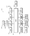
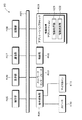
図6は、車載装置の構成の一例を示す。車載装置200は、例えば、制御部201と、アンテナ202と、チューナ203と、記憶部204と、電子ボリューム205と、アンプ部206と、スピーカ207と、操作部14と、表示制御部208と、表示部13と、第1振動制御部209と、第1振動部210と、第1入力部110aと、第2振動制御部211と、第2振動部212と、第2入力部110bと、GPS(Global Positioning System)モジュール213と、通信部214とを含む構成とされる。
"Configuration of in-vehicle device"
FIG. 6 shows an example of the configuration of the in-vehicle device. The in-
制御部201は、CPU(Central Processing Unit)およびCPUに対して接続されるRAM(Random Access Memory)およびROM(Read Only Memory)などから構成されている。ROMには、CPUにより読み込まれて動作されるプログラムなどが記憶されている。RAMは、CPUのワークメモリとして用いられる。CPUは、ROMに記憶されたプログラムに従い様々な処理を実行することによって、車載装置200の各部および全体の制御を行う。
The
アンテナ202は、テレビジョン放送やラジオ放送の電波を受信するためのアンテナであり、チューナ203に接続されている。チューナ203は、アンテナ202により受信された放送信号の復調やアナログ/デジタル変換、符号化されているデータの復号等の処理などを行い、映像データや音声データを復元する。映像データは、制御部201を介して表示制御部208に送られる。そして、表示制御部208の制御により、表示部13にテレビジョン放送の映像が表示される。音声データは、制御部201を介して電子ボリューム205、アンプ部206を介してスピーカ207へ送られ、スピーカ207により音声として出力される。
The
記憶部204は、車載装置200に内蔵される記憶装置および車載装置200に対して着脱自在とされる記憶装置の、少なくとも一方であり、それらの記憶装置に対して、記録や再生の処理を行うドライバを含む。記憶部204として、ハードディスク、フラッシュメモリ、光ディスク、光磁気ディスクなどが例示される。記憶部204には、例えば、オーディオデータや地図データなどが記憶される。
The
例えば、記憶部204に記憶されるオーディオデータに対して再生処理が行われ、再生処理を施されたオーディオデータが制御部201に送られる。制御部201による制御に応じて、オーディオデータが電子ボリューム205、アンプ部206を介してスピーカ207へ送られ、スピーカ207からオーディオデータが再生される。
For example, a reproduction process is performed on the audio data stored in the
電子ボリューム205は、制御部201の制御に基づき、チューナ203や記憶部204などから供給される音声データを増幅して音量を調整する。音量が調整された音声データは、アンプ部206に供給される。アンプ部206は、電子ボリューム205から供給された音声データを所定の増幅率でもって増幅し、スピーカ207に供給する。スピーカ207は、アンプ部206から供給された音声データを音声として外部に出力する。
Based on the control of the
操作部14は、ユーザが車載装置200への各種入力操作を行うためのものである。操作部14は例えば、ボタン、タッチスクリーン、スイッチなどにより構成される。また、操作部14は、表示部13と一体に構成されたタッチスクリーンとして構成してもよい。操作部14に対してユーザによる入力がなされると、その入力に対応した制御信号が生成され、制御信号が制御部201に出力される。そして、制御信号に応じた演算処理や制御が制御部201により行われる。なお、リモートコントローラ等の車載装置200を遠隔で操作する装置が操作部14に含まれるようにしてもよい。
The
表示制御部208は、制御部201による制御に応じて、表示部13の表示内容を制御する。表示制御部208は、入力部110に対する操作に応じて、例えば、表示部13に表示される画面を遷移する制御や、表示部13に表示されるカーソルを所定方向に移動する制御を行う。
The
さらに、表示制御部208は、ナビゲーションシステムの起動時に、地図データに基づく地図を表示部13に表示させ、自動車の現在位置を地図上にマッピングする処理を行う。地図データやおよび自動車の現在位置を示す情報は、例えば、制御部201から表示制御部208に供給される。さらに、表示制御部208は、表示される地図を拡大/縮小する処理や、自動車の移動方向に応じて地図の表示内容を適宜、更新する処理を行う。なお、表示制御部208の機能が制御部201に組み込まれていてもよい。
Further, when the navigation system is activated, the
表示部13は、上述したように、LCDや有機ELにより構成される。表示部13には、表示制御部208による制御に基づく表示がなされる。
As described above, the
第1振動制御部209は、制御部201による制御に応じて、第1振動部210の振動を制御する。第1振動制御部209は、例えば、制御部201による制御に応じて、第1振動部210に対して所定のパターンの電圧を印加する。
The first
第1振動部210は、第1入力部110aと一体的に構成され、例えば、圧電素子(ピエゾ)からなる。第1振動部210が、モータなどにより構成されてもよい。第1振動部210は、第1振動制御部209により印加される所定のパターンの電圧に応じて振動する。第1振動部210が振動することにより、第1入力部110aが振動する。
The
第2振動制御部211は、制御部201による制御に応じて、第2振動部212の振動を制御する。第2振動制御部211は、例えば、制御部201による制御に応じて、第2振動部212に対して所定のパターンの電圧を印加する。
The second
第2振動部212は、第2入力部110bと一体的に構成され、例えば、圧電素子(ピエゾ)からなる。第2振動部212が、モータなどにより構成されてもよい。第2振動部212は、第2振動制御部211により印加される所定のパターンの電圧に応じて振動する。第2振動部212が振動することにより、第2入力部110bが振動する。なお、第1振動制御部209および第2振動制御部211が共通の構成とされてもよい。
The
入力部110の形状等については、上述した通りである。入力部110に対して操作がなされると、操作に応じた操作信号が生成され、生成された操作信号が制御部201に供給される。
The shape and the like of the input unit 110 are as described above. When an operation is performed on the input unit 110, an operation signal corresponding to the operation is generated, and the generated operation signal is supplied to the
GPSモジュール213は、例えば、人工衛星からの電波を受信するGPSアンテナおよびGPSレシーバと、ジャイロセンサと、車速センサとを含む構成とされる。GPSアンテナ等により受信される電波に基づくデータや、各種センサにより得られるセンサ情報が制御部201に供給される。
The
制御部201は、人工衛星からの電波に基づいて自動車の現在位置を推定する。さらに、制御部201は、ジャイロセンサにより得られる情報に基づいて自動車が進行する方向(進行方向)を判別し、車速センサにより得られる情報に基づいて自動車が移動する距離(移動距離)を判別する。これらの判別結果を使用して自動車の現在位置を正確に判別する。制御部201は、自動車の現在位置に対応する地図データを読み出し、読み出した地図データと、自動車の現在位置を示す情報とを表示制御部208に供給する。表示制御部208による制御に応じて、表示部13に地図データ等が表示される。
The
通信部214は、例えば、外部と通信を行うための構成を総称したものである。通信部214により、例えば、電話やインターネットを行うことができる。電話は、電話機を持つ必要がない、いわゆるハンズフリーホンとして構成される。
For example, the
なお、制御部201は、図示しない構成に対する制御を行うようにしてもよい。例えば、自動車のエアーコンディショナのオン/オフや、風量の制御を制御部201が行うようにしてもよい。
Note that the
車載装置200の動作の一例について説明する。なお、車載装置200は、以下に説明する動作のほかに、公知の動作を行うことができる。
An example of the operation of the in-
入力部110に対する操作に応じて行われる動作の一例について説明する。入力部110に対する操作がなされると、入力部110において操作信号が生成される。操作信号が入力部110から制御部201に供給される。
An example of an operation performed in response to an operation on the input unit 110 will be described. When an operation is performed on the input unit 110, an operation signal is generated in the input unit 110. An operation signal is supplied from the input unit 110 to the
制御部201は、供給される操作信号に基づいて、例えば、入力部110が触れられた位置、触れられた際の押圧力およびを触れられている期間等を検出し、操作の内容を判別する。これらの検出処理が入力部110において行われ、検出処理の結果が制御部201に通知されるようにしてもよい。
Based on the supplied operation signal, the
制御部201は、判別した操作の内容に応じて表示部13の表示内容を変化させるための表示制御信号を生成する。表示制御信号が制御部201から表示制御部208に供給される。表示制御部208が表示制御信号に応じて動作することにより、表示部13に表示される表示内容が変化する。
The
さらに、入力部110に対する操作がなされた場合に、ドライバに対する報知動作が行われる。報知動作の一例について説明する。 Further, when an operation on the input unit 110 is performed, a notification operation for the driver is performed. An example of the notification operation will be described.
例えば、第1入力部110aに対するスライド操作がなされる。スライド操作に応じた操作信号が第1入力部110aから制御部201に対して供給される。制御部201は、第1入力部110aから供給される操作信号に基づいて、第1入力部110aに対してなされた操作がスライド操作であることを判別する。制御部201は、第1振動部210を振動させるための振動制御信号を生成し、この振動制御信号を第1振動制御部209に供給する。
For example, a slide operation is performed on the
第1振動制御部209は、制御部201から供給される振動制御信号に応じて所定のパターンの電圧を生成し、この電圧を第1振動部210に供給する。第1振動部210は、第1振動制御部209から供給される電圧に応じて振動する。第1振動部210が振動することにより第1入力部110aが振動する。第1入力部110aの振動が、ドライバにより知覚される。第2入力部110bに対してスライド操作がなされた場合も、同様にして、報知動作が行われる。
The first
「メニュー画面の一例」
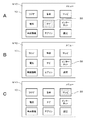
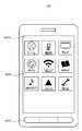
次に、入力部110に対する操作に応じた処理の具体例について説明する。図7は、表示部13に表示されるメニュー画面の一例を示す。メニュー画面とは、自動車で使用可能な機能に対応する項目(以下、適宜、アイコンと称する)が複数、表示された画面である。図7Aに示すように、表示部13のメニュー画面M10には、複数のアイコンとして「ラジオ」、「音楽」、「テレビ」、「電話」、「ナビ(カーナビゲーションの略称)」、「インターネット」、「車両情報」、「エアコン(エアーコンディショナの略称)」、「設定」が表示される。「車両情報」とは、例えば、動力源(ガソリンやバッテリ)の残量や、走行距離等である。「設定」は、例えば、表示部13の表示の明るさや文字の大きさなどである。
"Example of menu screen"
Next, a specific example of processing according to an operation on the input unit 110 will be described. FIG. 7 shows an example of a menu screen displayed on the
それぞれのアイコンは、文字ではなくマークで表示されてもよく、文字およびマークが組み合わされて表示されてもよい。図示されたアイコンとは異なるアイコンが表示されてもよい。さらに、各アイコンの配置位置を設定できるようにしてもよい。ドライバや助手席に座るユーザは、複数のアイコンの中から所望するアイコンを選択し、さらに、決定する操作を行うことにより、所望のアイコンに対応する機能を実行する。 Each icon may be displayed as a mark instead of a character, or a combination of a character and a mark may be displayed. An icon different from the illustrated icon may be displayed. Further, the arrangement position of each icon may be set. A driver or a user sitting in a passenger seat executes a function corresponding to a desired icon by selecting a desired icon from among a plurality of icons and further performing a determination operation.
複数のアイコンのうち、選択されているアイコンにはカーソルが表示される。カーソルとは、選択されているアイコンを他のアイコンと区別するための表示である。カーソルは、例えば、選択されているアイコンの周囲を囲う線や、色や輝度を他のアイコンと異なるようにして表示する、いわゆるハイライト表示などである。メニュー画面を起動させると、例えば、中央に配されるアイコンにカーソルが表示される。図7Aに示す例では、アイコン「ナビ」にカーソル30が表示されている。
A cursor is displayed on the selected icon among the plurality of icons. A cursor is a display for distinguishing a selected icon from other icons. The cursor is, for example, a so-called highlight display that displays a line surrounding the selected icon, a color or brightness different from those of other icons. When the menu screen is activated, for example, a cursor is displayed on an icon arranged in the center. In the example shown in FIG. 7A, the
「操作に応じた処理」
始めに、各操作のうちスライド操作に応じた処理の一例について説明する。第1入力部110aに対するスライド操作(第1の操作の一例)により、第1の変更の一例である、カーソルの水平方向(第1の方向の一例)への移動がなされる。第1入力部110aが配設される方向とカーソルの移動の方向(横軸)が対応している。第2入力部110bに対するスライド操作(第2の操作の一例)により、第2の変更の一例である、カーソルの垂直方向(第2の方向の一例)への移動がなされる。垂直方向は、第1入力部110aに対するスライド操作に応じてカーソルが移動する水平方向と直交または略直交する方向(適宜、略直交する方向と称する)である。第2入力部110bが配設される方向とカーソルの移動の方向(縦軸)とが対応している。
"Processing according to operation"
First, an example of processing according to the slide operation among the operations will be described. By the slide operation (an example of the first operation) on the
例えば、ドライバが第1入力部110aに親指F1を接触させ、親指F1を右方向に動かすスライド操作を行う。親指F1を動かす方向と対応する方向に、カーソル30が移動する。すなわち、図7Bに示すように、カーソル30がアイコン「ナビ」からアイコン「インターネット」へと移動する。この場合のカーソル30の移動回数は1回であり、移動距離は1アイコン分である。
For example, the driver performs a slide operation of bringing the thumb F1 into contact with the
さらに、ドライバが第2入力部110bに人差し指F2を接触させ、人差し指F2を上方向に動かすスライド操作を行う。人差し指F2を動かす方向と対応する方向に、カーソル30が移動する。すなわち、図7Cに示すように、カーソル30がアイコン「インターネット」からアイコン「テレビ」へと移動する。この場合のカーソル30の移動回数は1回であり、移動距離は1アイコン分である。
Furthermore, the driver performs a slide operation of bringing the index finger F2 into contact with the
入力部110に対する操作に応じて、報知動作が行われる。例えば、スライド操作が行われることにより、カーソル30がアイコン「ナビ」からアイコン「インターネット」に移動する(図7Aから図7Bへの遷移)。この場合に、第1振動部210を1秒程度、振動させる制御が行われ、この制御に応じて、第1入力部110aが1秒程度、1回振動する。この振動を知覚したドライバは、表示部13を見なくても、カーソル30が1アイコン分、移動したことを認識できる。
A notification operation is performed in response to an operation on the input unit 110. For example, when the slide operation is performed, the
例えば、図7Cに示す状態から、ドライバが第1入力部110aに親指F1を接触させ、親指F1を左方向に動かすスライド操作を2回、行う。2回のスライド操作に応じて、カーソル30がアイコン「テレビ」からアイコン「ラジオ」へと移動する。この場合のカーソル30の移動回数は2回であり、移動距離は、2アイコン分である。
For example, from the state shown in FIG. 7C, the driver performs a slide operation twice to bring the thumb F1 into contact with the
2回のスライド操作に応じて、第1入力部110aが2回、振動する。この振動を知覚したドライバは、表示部13を見なくても、カーソル30が2アイコン分、移動したことを認識できる。第2入力部110bに対する操作がなされた場合でも、同様にして、第2入力部110bが振動する。このように、カーソル30が移動できる場合には、操作がなされた入力部110が第1のパターンで振動する。例えば、操作がなされた入力部110が、カーソル30の移動回数分、1秒程度、振動する。
In response to the two slide operations, the
カーソル30は、例えば、アイコン「音楽」を経由するようにしてアイコン「ラジオ」に移動する。アイコン「音楽」を経由せずにアイコン「ラジオ」にカーソル30が表示されるようにしてもよい。
For example, the
なお、スライド操作に対応する方向に、カーソル30を移動できない場合がある。このような場合には、操作がなされた入力部110が第1のパターンと異なる第2のパターンにより振動する。
In some cases, the
例えば、図7Cに示すように、アイコン「テレビ」にカーソル30が表示されている場合を考える。例えば、第1入力部110aに対して親指F1を右方向に動かすスライド操作がなされても、操作の方向に対応するアイコンがなく、カーソル30を移動させることができない。このように、スライド操作に対応する方向にカーソル30を移動させることができない場合には、第2のパターンにより第1振動部210を振動させる制御が行われる。例えば、短い間隔でもって3回、第1振動部210を振動させる制御が行われる。3秒程度、継続して第1振動部210を振動させる制御が行われてもよい。
For example, as shown in FIG. 7C, consider a case where the
第1振動部210の振動がドライバによって知覚される。ドライバは、スライド操作に対応する方向にカーソル30が移動できないことを認識できる。アイコン「テレビ」にカーソル30が表示されている場合に、第2入力部110b上で人差し指F2を上方向に動かすスライド操作がなされたときも、同様の処理が行われる。
The vibration of the
なお、1個のタッチパッドを使用して、各方向に対するスライド操作が行われるようにしてもよい。しかしながら、例えば、1個のタッチパッドを振動させることにより、カーソルの移動をドライバに報知しても、タッチパッド全体が振動するだけであり、カーソルが移動する方向をドライバが認識することができない。 Note that a single touchpad may be used to perform a slide operation in each direction. However, for example, even if the driver is informed of the movement of the cursor by vibrating one touch pad, only the entire touch pad vibrates, and the driver cannot recognize the direction in which the cursor moves.
本技術では、カーソル30の移動方向に対応して、第1入力部110aおよび第2入力部110bが独立して配設されているため、カーソル30が移動する方向をドライバに対して報知できる。第1入力部110aが振動することにより、ドライバは、カーソル30が右方向または左方向に移動することを認識できる。第2入力部110bが振動することにより、ドライバは、カーソル30が上方向または下方向に移動することを認識できる。
In the present technology, since the
次に、第3の操作の一例である押し込み操作に応じた処理について説明する。上述したように、押し込み操作は、入力部110を閾値以上の押圧力でもって押圧する操作である。もちろん、ドライバは、入力部110を押し込む操作を行えばよく、閾値を意識する必要はない。なお、閾値より小さい範囲は不感帯として設定されており、制御が行われないようにされている。このため、ドライバが入力部110を指で触れる程度であれば、制御が行われることはない。但し、その指を左右方向等に動かすと、スライド操作として検知される。押し込み操作をより確実に検出するために、ハードスイッチとの組合せで押し込み操作が実現されてもよい。 Next, processing according to a push-in operation that is an example of a third operation will be described. As described above, the pressing operation is an operation of pressing the input unit 110 with a pressing force equal to or greater than a threshold value. Of course, the driver only needs to perform an operation of pressing the input unit 110 and does not need to be aware of the threshold value. Note that a range smaller than the threshold is set as a dead zone, and control is not performed. For this reason, control is not performed as long as the driver touches the input unit 110 with a finger. However, when the finger is moved in the left-right direction or the like, it is detected as a slide operation. In order to detect the push-in operation more reliably, the push-in operation may be realized in combination with a hard switch.
入力部110に対する押し込み操作がなされると、アイコンの選択が確定され、当該アイコンに対応する機能が実行される。例えば、図7Aに示すように、アイコン「ナビ」にカーソル30が表示される場合に、第1入力部110aに対する押し込み操作がなされる。押し込み操作に応じて、アイコン「ナビ」に対応する機能、すなわち、カーナビゲーションシステムが起動する。カーナビゲーションシステムが起動することにより、表示部13には、例えば、地図が表示される。例えば、図7Bに示すように、アイコン「インターネット」にカーソル30が表示される場合に、第1入力部110aに対する押し込み操作がなされると、表示部13の表示がインターネットの画面に遷移する。
When a pressing operation is performed on the input unit 110, the selection of the icon is confirmed and a function corresponding to the icon is executed. For example, as illustrated in FIG. 7A, when the
第2入力部110bに対して押し込み操作がなされてもよい。第1入力部110aおよび第2入力部110bに対して、略同時に押し込み操作がなされてもよい。しかしながら、第1入力部110aはドライバと対向する面に形成され、かつ、親指で操作されることから、第1入力部110aに対して押し込み操作を行う方が操作としては容易である。このため、第1入力部110aのみが押し込み操作を受け付ける構成としてもよい。
A pressing operation may be performed on the
次に、押し込みスライド操作に応じた処理について説明する。第1入力部110aに対する押し込みスライド操作(第4の操作の一例)により、第1の変更の一例である、表示部の表示の水平方向(第1の方向の一例)への移動がなされる。第1入力部110aが配設される方向とカーソルの移動の方向(横軸)が対応している。第2入力部110bに対する押し込みスライド操作(第5の操作の一例)により、第2の変更の一例である、表示部の表示の垂直方向(第2の方向の一例)への移動がなされる。垂直方向は、第1入力部110aに対する押し込みスライド操作に応じて表示が遷移する水平方向と略直交する方向(適宜、略直交する方向と称する)である。第2入力部110bが配設される方向と表示が遷移する方向と(縦軸)が対応している。
Next, processing according to the push-in slide operation will be described. The push-and-slide operation (an example of the fourth operation) on the
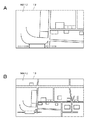
図8Aは、表示部13に表示されるメニュー画面M10の一例を示す。表示部13には、6個のアイコン(アイコン「ラジオ」、アイコン「音楽」、アイコン「テレビ」、アイコン「電話」、アイコン「ナビ」およびアイコン「インターネット」)が表示されている。表示部13の表示領域に制約がある場合には、全てのアイコンを表示することができない。このような場合は、表示部13の表示を遷移させることにより、他のアイコンを表示部13に表示する。なお、表示を遷移できる方向が矢印等のマークで示されてもよい。例えば、右方向を示すマーク32aが6個のアイコンとともに表示部13に表示される。
FIG. 8A shows an example of the menu screen M10 displayed on the
ドライバは、第1入力部110aに対して、右方向への押し込みスライド操作を行う。右方向への押し込みスライド操作に応じて、図8Aに示す6個のアイコンが右方向にスライドするとともに、表示部13の左側から他のアイコンが表示部13に進入するようにスライドする。そして、表示部13の表示内容が図8Bに示すメニュー画面M11に変化する。表示部13には、3個のアイコン(アイコン「車両情報」、アイコン「エアコン」およびアイコン「設定」)が表示される。表示が更新されたことに応じて、新たなに表示を遷移できるようになった方向(左方向)がマーク32bにより示される。
The driver performs a push-and-slide operation to the right with respect to the first input unit 110a. 6 icons shown in FIG. 8A slide in the right direction according to the push-in slide operation in the right direction, and the other icons slide into the
ドライバが左方向への押し込みスライド操作を行うことにより、表示部13の表示が図8Bに示す表示から図8Aに示す表示に遷移する。このように、押し込みスライド操作によりメニュー画面の表示を遷移させることができる。
When the driver performs a push-down slide operation in the left direction, the display on the
なお、スライド操作によりカーソル30を移動させることにより所定のアイコンを選択する処理、および、押し込み操作により所定のアイコンの選択を確定し、そのアイコンに対応する機能を実行する処理については、上述した通りである。さらに、メニュー画面が上下方向に遷移するようにし、第2入力部110bに対する押し込みスライド操作に応じてメニュー画面が切り換えられてもよい。
As described above, the process of selecting a predetermined icon by moving the
押し込みスライド操作による表示の遷移は、メニュー画面の遷移に限られない。例えば、押し込みスライド操作により、表示部13の表示内容をスクロールできる。例えば、インターネットの機能が実行され、図9Aに示すように、表示部13にウェブページ35が表示されている。さらに、スクロールできる方向が矢印のマーク36aにより示されている。
The transition of the display by the push slide operation is not limited to the transition of the menu screen. For example, the display content of the
ドライバは、第2入力部110bに対して下方向への押し込みスライド操作を行うことにより、ウェブページ35を下方向にスクロールすることができる。図9Bは、スクロール後の表示の一例を示す。スクロールが可能な方向(上方向および下方向)がマーク36bおよびマーク36cにより示される。ドライバは、さらに、第2入力部110bに対する上方向または下方向への押し込みスライド操作を行うことにより、ウェブページ35を上方向または下方向にスクロールできる。
The driver can scroll the
ドライバがウェブページ35を閲覧することは安全上、好ましくない。しかしながら、ドライバ以外のユーザが閲覧する際に、ウェブページ35のスクロールする方法を知らない場合がある。このような場合でも、ドライバは、視線をそらすことなく、表示部13に表示されるウェブページ35をスクロールする操作を行うことができる。この操作に応じてウェブページ35がスクロールする。
For safety reasons, it is not preferable for the driver to browse the
次に、押し込み長押し動作に応じた処理について説明する。第1入力部110aに対する押し込み長押し操作(第6の操作の一例)により、第1の変更の一例である、表示部の表示が拡大される。第2入力部110bに対する押し込み長押し操作(第7の操作の一例)により、第2の変更の一例である、表示部の表示が縮小される。第1入力部110aに対する押し込み長押し操作に応じて、表示部13の表示が縮小し、第2入力部110bに対する押し込み長押し操作に応じて、表示部13の表示が拡大するようにしてもよい。
Next, processing according to the push-in and long-pushing operation will be described. The display on the display unit, which is an example of the first change, is enlarged by a long press operation (an example of a sixth operation) on the
例えば、図10Aに示すように、第1入力部110a対する押し込み長押し操作に応じて、表示部13の表示される地図MA10が拡大する。図10Bに示すように、第2入力部110b対する押し込み長押し操作に応じて、表示部13の表示される地図MA10が縮小する。
For example, as shown in FIG. 10A, the map MA10 displayed on the
例えば、図11Aに示すように、表示部13にウェブページ35が表示され、ウェブページ35をスクロールできる方向(下方向)がマーク38aにより示されている。ウェブページ35が表示された状態で第1入力部110a対する押し込み長押し操作がなされると、図11Bに示すようにウェブページ35の一部が拡大表示される。表示が更新されたことに応じて、新たなに表示をスクロール可能となる方向(右方向)がマーク38bにより示される。
For example, as shown in FIG. 11A, a
さらに、第1入力部110aに対して右方向への押し込みスライド操作がなされることにより、図11Cに示すように、ウェブページ35を右方向にスクロールできる。表示が更新されたことに応じて、新たなにスクロール可能となる方向(左方向)がマーク38cにより示される。
Further, by pushing and sliding the
<2.第2の実施形態>
「車載装置の構成」
図12は、第2の実施形態における車載装置の構成の一例を示す。車載装置300の構成のうち、車載装置200の構成と同一部分又は相応する部分に構成には、共通の参照符号を付してある。以下、車載装置300が有する構成のうち、車載装置200と異なる構成を中心に説明する。
<2. Second Embodiment>
"Configuration of in-vehicle device"
FIG. 12 shows an example of the configuration of the in-vehicle device in the second embodiment. In the configuration of the in-
車載装置300は、通信部303およびアプリケーションプロセッサ304を備える。通信部303は、携帯端末20と通信を行うものである。通信の方式としてBluetooth(登録商標)を用いる場合、シリアルポートプロファイルを用いて、車載装置300と携帯端末20間で、アプリケーション情報、操作情報などの送受信を行われる。また、車載装置300と携帯端末20との接続にUSBを用いる場合には、iAPを用いてアプリケーション情報、操作情報などの任意の情報の送受信が可能となる。ただし、接続方法はいずれの方法であってもよい。また、Bluetooth、USB以外にも任意のデータ通信が可能な接続方法であればどのようなものを採用してもよい。なお、通信部303は、上述した通信部214と共通の構成でもよい。
The in-
アプリケーションプロセッサ304は、携帯端末20の動作と連動して車載装置200で所定の処理を行うものである。アプリケーションプロセッサ304は、所定のアプリケーションを実行することにより情報取得部305および情報送信部306として機能する。
The application processor 304 performs predetermined processing in the in-
情報取得部305は、携帯端末20から送信されたアプリケーション情報を、通信部303を介して取得する。例えば、情報取得部305は、携帯端末20から送信されたメニュー画面の構成に関する情報(適宜、メニュー画面情報と称する)を、通信部303を介して取得する。メニュー画面情報とは、メニュー画面を構成する複数のアイコンや、アイコンの配列等を示す情報である。
The
情報取得部305により取得されたメニュー画面情報が制御部201を介して表示制御部208に供給される。表示制御部208は、制御部201から供給されるメニュー画面情報に基づくメニュー画面を表示部13に表示する。すなわち、車載装置300の表示部13に、携帯端末20のメニュー画面が表示される。好ましくは、携帯端末20のメニュー画面と同様のアイコンの配列のメニュー画面が表示部13に表示される。但し、表示部13の表示領域は様々であるため、表示部13の表示領域の大きさに応じて、アイコンの配列が適宜、変更されてもよい。
The menu screen information acquired by the
情報送信部306は、車載装置300側でなされた操作情報を携帯端末20に送信する。例えば、携帯端末20のメニュー画面が表示部13に表示される。そして、入力部110に対してスライド操作がなされ、所定のアイコンが選択される。さらに、入力部110に対して押し込み操作がなされ、アイコンの選択が確定する。情報送信部306は、アイコンを示す情報を操作情報として携帯端末20に送信する。詳細は後述するが、携帯端末20は、操作情報に含まれるアイコンに対応する機能を実行する。このように、車載装置300を使用して携帯端末20を制御できる。
The
「携帯端末の構成」
図13は、携帯端末20の構成の一例を示す。携帯端末20は、データバス401を備え、データバス401に対して、制御部402、ネットワークインターフェース403、信号処理部404、操作部405、表示部406、通信部407、記憶部408およびアプリケーションプロセッサ409が接続されている。
"Configuration of mobile device"
FIG. 13 shows an example of the configuration of the
制御部402は、例えば、CPU、RAMおよびROMなどから構成されている。ROMには、CPUにより読み込まれて動作されるプログラムなどが記憶されている。RAMは、CPUのワークメモリとして用いられる。CPUは、ROMに記憶されたプログラムに従い様々な処理を実行することによって、携帯端末20の各部および全体の制御を行う。
The
ネットワークインターフェース403は、例えば、所定のプロトコルに基づいて外部基地局などとの間でデータの送受信を行うものである。通信方式は無線LAN(Local Area Network)、Wi−Fi(Wireless Fidelity)(登録商標)、3G回線を用いた通信など、どのような方式でもよい。ネットワークインターフェース403による通信により、携帯端末20はインターネット接続、他者との通話などを行うことが可能となる。
The
信号処理部404は、変復調器、A/D(Analog to Digital)変換器、D/A(Digital to Analog)変換器、音声コーデックなどを備えている。信号処理部404の変復調器で、送信する音声信号を変調し、あるいは受信した信号を復調する。送信する信号は、A/D変換器でデジタル信号に変換され、受信した信号はD/A変換器でアナログ信号に変換される。そして信号処理部404には、音声を出力するスピーカ410と、音声を入力するマイクロホン412とが接続されている。
The
操作部405は、ユーザが携帯端末20に対して各種入力を行うための入力手段である。例えば、ボタン、タッチスクリーン、スイッチなどにより構成されている。また、操作部405は、表示部406と一体に構成されたタッチスクリーンとして構成してもよい。操作部405に対してユーザによる入力操作がなされると、その入力に対応した制御信号が生成され、生成された制御信号が制御部402に出力される。そして、制御部402によりその制御信号に対応した演算処理や制御が行われる。
The
表示部406は、例えば、LCD、有機ELパネルなどにより構成された表示手段である。表示部406には、携帯端末20の各種操作のメニューを表示し、複数のアイコンが配列されたメニュー画面、楽曲リスト、再生中の楽曲情報(アーティスト名、曲名など)、動画コンテンツ、画像コンテンツなどが表示される。
The
通信部407は、Bluetooth、USB(Universal Serial Bus)接続などの方法により車載装置300と通信を行うための通信モジュールである。通信部407における通信方法としては、無線通信であるBluetooth、有線通信であるUSBによる通信などがある。Bluetooth通信を行うBluetoothモジュールは、Bluetooth方式の近距離無線通信によるデータの送受信が可能なモジュールである。Bluetoothモジュールによって、車載装置300とのデータのやり取りが行われる。
The
Bluetoothモジュールは、アンテナ、信号処理部など(図示を省略している)を備える。例えば外部のBluetooth機器である車載装置300に音声データを送信する場合等、Bluetoothモジュールは、信号処理部によって送信する音声データに所定の信号処理を施し、その音声データを内蔵するアンテナを介して車載装置300に送信する。また、車載装置300に音声データを送信する場合等、Bluetoothモジュールは、車載装置300から送信された音声データを内蔵するアンテナで受信し、内蔵する信号処理部404に供給する。そして、信号処理部において音声データに所定の信号処理を施すことによって音声信号を生成する。これにより、携帯端末20で再生した音声データを車載装置300から出力すること、および、車載装置300で再生した音声データを携帯端末20から出力することができる。
The Bluetooth module includes an antenna, a signal processing unit, and the like (not shown). For example, when transmitting audio data to the in-
通信部407における通信方式として有線通信であるUSBを用いる場合には、USBケーブルによって車載装置300と携帯端末20とが接続される。音声データはUSBケーブルを介して携帯端末20から車載装置300に供給される。
When USB that is wired communication is used as a communication method in the
よって、携帯端末20と車載装置300とを接続し、携帯端末20が保存する楽曲データを再生し、その楽曲が音声として車載装置300から出力されるようにすることもできる。
Therefore, it is possible to connect the
ただし、接続方法はいずれの方法であってもよい。また、Bluetooth、USB以外にも任意のデータ通信が可能な接続方法であればどのようなものを採用してもよい。また、通信方式は、携帯端末20の機種、OS(Operation System)の種類などに基づいて適宜選択される。
However, any connection method may be used. In addition to Bluetooth and USB, any connection method capable of arbitrary data communication may be adopted. The communication method is appropriately selected based on the model of the
記憶部408は、例えば、HDD、フラッシュメモリなどの大容量記憶媒体から構成されており、携帯端末20によって再生される楽曲などのコンテンツデータなどを保存するものである。楽曲データは、WAV(RIFF waveform Audio Format)、またはMP3(MPEG Audio Layer-3)、AAC(Advanced Audio Coding)などの方式で音声圧縮された状態で記憶部408に記憶される。また、楽曲のアーティスト名、アルバム名、曲名、総再生時間、再生時間情報などを含む楽曲情報も楽曲データのメタデータとして記憶部408に保存されている。楽曲情報は例えば、CDDB(Compact Disc Data Base)を利用することにより取得することができる。また、ユーザが任意に設定できるようにしてもよい。
The
アプリケーションプロセッサ409は、例えば、CPU、ROM、RAMなどから構成され、携帯端末20にインストールされた各種アプリケーションを実行する処理部である。アプリケーションとしては、例えば、音楽再生、動画再生、地図、天気、ナビゲーション、ゲーム、インターネットブラウザ、動画共有サイト利用、計算機などの様々な種類がある。
The
情報取得部421は、例えば、車載装置300から送信される操作情報を取得する。操作情報には、アイコンを示す情報が含まれる。情報取得部421は、取得した操作情報を制御部402に供給する。制御部402は、操作情報に含まれるアイコンに対応する機能を実行する。
The
情報送信部422は、例えば、車載装置300に対して、アプリケーション情報の一例であるメニュー画面情報を送信する。なお、アプリケーション情報は、メニュー画面情報に限定されない。例えば、携帯端末20の表示部406の表示内容が車載装置300に対して送信され、車載装置300の表示部13に表示されるようにしてもよい。すなわち、携帯端末20の表示部406に表示される表示内容が、携帯端末20と車載装置300との間で共有される。
For example, the
スピーカ410は音声を出力するための音声出力手段であり、信号処理部404により所定の処理が施された音声信号などを音声として出力する。これによりユーザは通話音声、携帯端末20に保存された音声データなどを聴取することができる。また、マイクロホン411は通話、音声による指示入力などのために音声を携帯端末20に入力するためのものである。マイクロホン411から入力された音声は信号処理部404によって所定の処理が施される。
The
以上のようにして携帯端末20が構成されている。携帯端末20としては、携帯電話機、スマートフォン、携帯音楽プレーヤ、タブレット端末などがある。また、図示はしないが、携帯端末20には撮像部と画像処理部などからなるカメラ機能、ラジオ機能などが設けられていてもよい。
The
図14は、携帯端末20の外観の一例およびメニュー画面の一例である。携帯端末20の筺体には、例えば、操作部405および表示部406が配設されている。表示部406には、メニュー画面M20が表示され、携帯端末20で使用可能なアプリケーションに対応するアイコンが複数、表示されている。例えば、アイコン「ゲーム」、アイコン「電話」、アイコン「テレビ」、アイコン「カメラ」、アイコン「インターネット」、アイコン「マップ」アイコン「ミュージック」、アイコン「ナビ」およびアイコン「設定」が表示部406に表示される。
FIG. 14 shows an example of the appearance of the
表示部406の所定のアイコンに対してタップ操作がなされることにより、タップ操作がなされたアイコンに対応する機能が実行される。タップ操作とは、指を表示部の表面に1回、接触させる操作である。携帯端末20に対して、タップ操作のほかに、例えば、ホールド操作、ドラッグ操作、フリック操作と称される操作が可能とされる。ホールド操作とは、表示部の表面の所定箇所に指を接触させ、指の接触を所定時間以上、継続する操作である。ドラッグ操作とは、表示部の表面に指を接触させたまま、指を任意の方向に移動させる操作である。フリック操作とは、表示部の表面の1点に指を接触させ、そのまま任意の方向に素早くはじくように指を移動させる操作である。
By performing a tap operation on a predetermined icon on the
「車載装置と携帯端末との間の情報の共有」
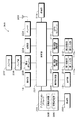
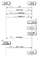
車載装置300と携帯端末20との間で情報を共有するための処理の一例について、図15を参照して説明する。始めに、ステップS1において、車載装置300と携帯端末20との接続が行われる。接続は上述したように双方の通信部においてBluetooth、USB接続などの方法により行われる。Bluetoothで接続された場合にはシリアルポートプロファイルを利用して車載装置300と携帯端末20間の情報の送受信が行われる。USBにより接続された場合にはiAPを利用して車載装置300と携帯端末20間の情報の送受信が行われる。そして、処理がステップS2に進む。
“Sharing information between in-vehicle devices and mobile devices”
An example of processing for sharing information between the in-
ステップS2おいて、車載装置300から携帯端末20に対して接続完了通知が送信される。なお、反対に、携帯端末20から車載装置300へ接続完了通知がなされるようにしてもよい。そして、処理がステップS3に進む。
In step S <b> 2, a connection completion notification is transmitted from the in-
ステップS3では、車載装置300から携帯端末20に対して、メニュー画面情報の取得要求がなされる。そして、処理がステップS4に進む。ステップS4では、メニュー画面情報の取得要求に応じて、携帯端末20から車載装置300に対してメニュー画面情報が表示される。そして、処理がステップS5に進む。
In step S <b> 3, the in-
ステップS5では、車載装置300の表示部13にメニュー画面が表示される。例えば、車載装置300の機能に対応したメニュー画面と、携帯端末20の機能に対応したメニュー画面とが切り替え可能に表示される。そして、処理がステップS6に進む。
In step S5, a menu screen is displayed on the
ステップS6では、入力部110を使用したスライド操作等の操作が受け付けられる。そして、処理がステップS7に進む。ステップS7では、押し込み操作が行われ、所定のアイコンの選択が確定される。押し込み操作に応じて、車載装置300の所定の機能が実行される。携帯端末20の機能に対応するアイコンの選択が確定される場合には、ステップS8に示す処理が行われる。
In step S6, an operation such as a slide operation using the input unit 110 is accepted. Then, the process proceeds to step S7. In step S7, a push-in operation is performed, and selection of a predetermined icon is confirmed. A predetermined function of the in-
ステップS8では、車載装置300から携帯端末20に対して操作情報が送信される。操作情報は、例えば、ステップS7において選択が確定されたアイコンを示す情報を含む。そして、処理がステップS9に進む。
In step S <b> 8, operation information is transmitted from the in-
ステップS9では、携帯端末20が操作情報に応じた動作を行う。すなわち、操作情報に含まれるアイコンに対応した機能が、携帯端末20において実行される。このように、入力部110に対する操作により、携帯端末20を制御することができる。
In step S9, the
さらに、ステップS10およびステップS11の処理が行われてもよい。例えば、ステップS9において、携帯端末20によりオーディオデータが再生されたとする。オーディオデータが再生されると、携帯端末20の表示部406には、再生中のオーディオデータに関する情報が表示される。表示部406には、アーティスト名や、ジャケット写真、オーディオデータ再生経過時間などが表示される。そして、処理がステップS10に進む。
Furthermore, the process of step S10 and step S11 may be performed. For example, it is assumed that audio data is reproduced by the
ステップS10では、携帯端末20から車載装置300に対して、表示部406の表示に対応する表示データがリアルタイムに送信される。送信されたデータが車載装置300により受信される。受信された表示データは、アプリケーションプロセッサ304による制御により、表示制御部208に供給される。そして、処理がステップS11に進む。
In step S10, display data corresponding to the display on the
ステップS11において、表示制御部208は、供給される表示データに基づいて動作する。表示制御部208が動作することにより、表示部13には、再生中のオーディオデータに関する情報が表示され、表示部13の表示が更新される。このように、車載装置300および携帯端末20のそれぞれの表示部に表示される内容が同一または略同一になるような制御が行われてもよい。
In step S11, the
さらに、携帯端末20から車載装置300に対してオーディオデータが送信され、送信されたオーディオデータが車載装置300のスピーカ207から再生されるようにしてもよい。
Furthermore, audio data may be transmitted from the
なお、車載装置300と携帯端末20との間でなされる情報を供給する処理(ペアリング処理などと称される場合もある)は、例示した処理に限られない。例示した処理と異なる公知の処理を適用することができる。
In addition, the process (it may be called a pairing process etc.) which supplies the information performed between the vehicle-mounted
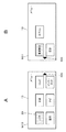
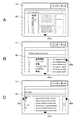
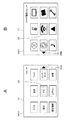
図16は、図15のステップS5におけるメニュー画面の表示の一例を示す。図16Aに示すように、表示部13には、自動車の機能に対応する複数のアイコンが表示されるメニュー画面M30が表示される。メニュー画面M30からユーザ登録メニュー画面M31に切り替えることが可能とされる。図16Bに示すように、ユーザ登録メニュー画面M31は、携帯端末20の機能に対応する複数のアイコンが表示される画面である。メニュー画面M31におけるアイコンの配列は、例えば、メニュー画面M20(図14参照)におけるアイコンの配列と同一とされる。
FIG. 16 shows an example of the menu screen display in step S5 of FIG. As shown in FIG. 16A, the
メニュー画面M30にはカーソル30が表示されるとともに、表示を遷移可能な方向を表すマーク39aが示される。メニュー画面M31にはカーソル30が表示されるとともに、表示を遷移可能な方向を表すマーク39bが示される。
A
ドライバは、第1入力部110aに対して右方向への押し込みスライド操作を行うことにより、メニュー画面M30からユーザ登録メニュー画面M31に切り替えることができる。反対に、ドライバは、第1入力部110aに対して、左方向への押し込みスライド操作を行うことにより、ユーザ登録メニュー画面M31からメニュー画面M30に切り替えることができる。第2入力部110bに対する上下方向への押し込みスライド操作により、ユーザ登録メニュー画面M31およびメニュー画面M30を上下方向に切り替えできるようにしてもよい。
The driver can switch from the menu screen M30 to the user registration menu screen M31 by performing a right-side push slide operation on the
表示部13にユーザ登録メニュー画面M31を表示させた状態でスライド操作がなされると、ユーザ登録メニュー画面M31におけるカーソル30が移動され、所定のアイコンが選択状態となる。さらに、押し込み操作に応じてアイコンの選択を確定でき、当該アイコンに対応する機能が携帯端末20において実行される。これらの操作および操作に応じた処理は、第1の実施形態におけるメニュー画面M10に対する操作等と同様であるので、重複した説明を省略する。
When a slide operation is performed with the user registration menu screen M31 displayed on the
なお、車載装置300に携帯端末20との間の接続が確立した場合には、表示部13には、ユーザ登録メニュー画面M31が表示されることが好ましい。
When the connection between the in-
一般に、携帯端末20は、車載装置300に比べて頻繁に使用されるものである。このため、メニュー画面M20におけるアイコンの配列をユーザ(ドライバ)がある程度、記憶するものである。ユーザ登録メニュー画面M31およびメニュー画面M20におけるアイコンの配列が同一または略同一にすることで、ドライバは、どの方向に何回、カーソルを移動すれば所望のアイコンに到達かを、表示部13を見なくても判断できる。但し、カーソル30の初期位置をドライバが認識する必要があるため、カーソル30の初期位置が、例えば、中央のアイコンになるように設定されることが好ましい。ドライバは、表示部13を見ずに入力部110を適宜、操作することにより、携帯端末20の所定の機能を実行できる。
In general, the
さらに、入力部110に対する操作は、携帯端末20に対して可能な操作と同一または類似した操作である。例えば、入力部110に対するスライド操作は、ドラッグ操作に同一または類似する。押し込み操作は、タップ操作に同一または類似する。押し込みスライド操作は、フリック操作と同一または類似する。押し込み長押し操作は、ホールド操作と同一または類似する。
Furthermore, the operation on the input unit 110 is the same as or similar to the operation that can be performed on the
例えば、ステアリングホイールの近傍にレバー装置を設けてブランド操作を行う場合には、レバーを動かす方向や、その操作に対応した表示の変化などをドライバが習得しなければならず、不慣れな操作を行わなければならない。しかしながら、入力部110に対する操作は、携帯端末20に対して可能な操作と同一または類似した操作であるため、ドライバは、新たな操作のやり方を習得する必要がない。すなわち、携帯端末20に対して日頃、行う操作と同一または類似する操作を、運転中に行うことができる。
For example, when performing a brand operation by installing a lever device in the vicinity of the steering wheel, the driver must learn the direction in which the lever is moved and the display change corresponding to the operation. There must be. However, since the operation on the input unit 110 is the same as or similar to the operation that can be performed on the
<3.変形例>
以上、本技術の一実施形態について説明したが、本技術は、上述した実施形態に限られることなく、種々の変形が可能である。
<3. Modification>
Although one embodiment of the present technology has been described above, the present technology is not limited to the above-described embodiment, and various modifications can be made.
「変形例1」
第1入力部110aおよび第2入力部110bが配設される位置は、適宜、変更できる。例えば、図17に示すように、第1入力部110aがスポーク部102aの表面に配設されてもよい。さらに、図18に示すように、第1入力部110aおよび第2入力部110bを、ステアリングパッドの同一の面に配設してもよい。例えば、スポーク部102aの表面に第1入力部110aを配設し、スポーク部102bの表面に第2入力部110bを配設してもよい。さらに、入力部110を3以上、配設し、操作を受け付けることができる入力部を設定できるようにしてもよい。例えば、複数の入力部のうち、ドライバの利き手に対応する入力部のみを有効とする設定がなされる。
"
The positions where the
「変形例2」
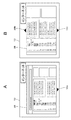
入力部110が配設される装置は、ステアリングパッドに限られない。シフトレバー15に入力部110が配設されてもよい。図19Aはシフトレバー15の右側面15bの一例を示す。シフトレバー15の右側面には、リリースボタン17が配設されている。リリースボタン17は、シフトレバー15を例えば、R(リバース)やP(パーキング)などの位置に移動させる際に、親指の指先付近で押されるボタンである。リリースボタン17の下側に、第1入力部110aが配設されてもよい。第1入力部110aは、自動車の進行方向に延在し、例えば、湾曲した帯状をなす。第1入力部110aが配設される位置は、シフトレバー15が把持される際に親指で操作可能な範囲の位置である。
"
The device in which the input unit 110 is disposed is not limited to the steering pad. An input unit 110 may be disposed on the
図19Bは、シフトレバー15の前面15dの一例を示す。シフトレバー15の前面15dには、第2入力部110bが配設される。第2入力部110bは、自動車の進行方向と略直交する方向に延在し、例えば、帯状をなす。第2入力部110bが湾曲した形状とされてもよい。第2入力部110bが配設される位置は、シフトレバー15が把持される際に人差し指または中指で操作可能な範囲の位置である。このように、入力部110は、自動車の走行時に操作される装置もしくはその近傍に配設される。必ずしも操作される装置に限らず、運転席の周囲に配される装置(例えば、運転席側のドアに形成されるドアアームレストの表面)に、入力部110が配設されてもよい。
FIG. 19B shows an example of the
「その他の変形例」
上述した実施形態において例示される複数の操作のうちの一部の操作を受け付けることが可能な入力装置として、本技術が構成されてもよい。例示した操作とは異なる操作を受け付ける入力装置として、本技術が構成されてもよい。
"Other variations"
The present technology may be configured as an input device capable of accepting a part of a plurality of operations exemplified in the above-described embodiments. The present technology may be configured as an input device that receives an operation different from the illustrated operation.
なお、入力部110が静電容量型のタッチスクリーンなどで構成されてもよい。この場合には、スライド操作や押し込みスライド操作において、親指F1の指先を必ずしも入力部110に接触する必要はなく、入力部110の操作面の近傍に親指F1の指先を近づければよい。すなわち、「指を接触させる」との用語の意味が、操作が検出可能な位置に指を近づけることと解釈されてもよい。 Note that the input unit 110 may be configured with a capacitive touch screen or the like. In this case, the fingertip of the thumb F1 is not necessarily in contact with the input unit 110 in the slide operation or the push-in slide operation, and the fingertip of the thumb F1 may be brought close to the operation surface of the input unit 110. That is, the meaning of the term “contact the finger” may be interpreted as bringing the finger close to a position where the operation can be detected.
入力部110は、タッチパッドに限定されない。入力部110が例えば、回転可能なダイヤルにより構成されてもよい。第1入力部110aおよび第2入力部110bのうち、一方が湾曲した帯状をなすタッチパッドにより構成され、他方がダイヤルにより構成されてもよい。
The input unit 110 is not limited to a touch pad. The input unit 110 may be configured by a rotatable dial, for example. One of the
第1入力部110aおよび第2入力部110bに対する操作の方向と対応する方向に、使用頻度の高い機能に対応するアイコンを配置してもよい。例えば、メニュー画面における中央に、使用頻度の最も高い機能に対応するアイコンを表示する。そのアイコンの上下左右の位置に使用頻度の高い機能に対応するアイコンを表示するようにしてもよい。これにより、第1入力部110aおよび第2入力部110bに対する操作の回数を少なくすることができる。この場合は、アイコンに対する押し込み操作の回数がアイコン毎にログとして記憶される。
You may arrange | position the icon corresponding to the function with high use frequency in the direction corresponding to the direction of operation with respect to the
カーソルが移動した先のアイコンの機能をユーザに音声により報知してもよい。これにより、ユーザは、選択されているアイコンが所望のアイコンか否かを、表示部13を見ることなく認識できる。そして、入力部110に対する操作をさらに続けるか否かを判断できる。
The function of the icon to which the cursor has moved may be notified to the user by voice. Thereby, the user can recognize whether or not the selected icon is a desired icon without looking at the
入力部110に対する押し込み長押し操作がなされる場合に、押し込み長押し操作の押圧力に比例して、拡大または縮小の速度を変化させてもよい。押圧力を多段階に検出できる構成としてもよい。スライド操作以外の操作(例えば、長押しスライド操作)がなされた際に、報知動作が行われるようにしてもよい。報知動作における第1のパターンおよび第2のパターンは、振動の強弱が異なるものであってもよい。第1入力部110aおよび第2入力部110bに対して略同時にスライド操作を行うことにより、カーソル30が斜め方向に移動するようにしてもよい。指先に取り付けられた器具を介して、第1入力部110aおよび第2入力部110bに対する操作がなされてもよい。本技術の入力装置が、船舶や飛行機を操縦するための装置に配設されてもよい。
When a long pressing operation is performed on the input unit 110, the enlargement or reduction speed may be changed in proportion to the pressing force of the long pressing operation. It is good also as a structure which can detect pressing force in multiple steps. The notification operation may be performed when an operation other than the slide operation (for example, a long press slide operation) is performed. The first pattern and the second pattern in the notification operation may be different in vibration intensity. The
さらに、本技術は、装置に限らず、方法や、その方法を実現するためのプログラム、プログラムが記録された記録媒体として実現することができる。さらに、入力部を有する構成と、入力部に対する操作に応じた表示が行われる構成とを含むシステムとして、本技術を実現することもできる。 Furthermore, the present technology is not limited to an apparatus, and can be realized as a method, a program for realizing the method, and a recording medium on which the program is recorded. Furthermore, the present technology can also be realized as a system including a configuration having an input unit and a configuration in which display is performed according to an operation on the input unit.
なお、実施形態および変形例における構成および処理は、技術的な矛盾が生じない範囲で適宜、組み合わせることができる。例示した処理のおける個々の処理の順序は、技術的な矛盾が生じない範囲で適宜、変更できる。 Note that the configurations and processes in the embodiments and the modifications can be combined as appropriate within a range where no technical contradiction occurs. The order of the individual processes in the illustrated processes can be changed as appropriate as long as no technical contradiction occurs.
本技術は、例示した処理が複数の装置によって分散されて処理される、いわゆるクラウドシステムに対して適用することもできる。実施形態および変形例において例示した処理が実行されるシステムであって、例示した処理の少なくとも一部の処理が実行される装置として、本技術を実現することができる。 The present technology can also be applied to a so-called cloud system in which the exemplified processing is distributed and processed by a plurality of devices. The present technology can be realized as a system in which the processes exemplified in the embodiment and the modification are executed, and an apparatus in which at least a part of the exemplified processes is executed.
本技術は、以下の構成をとることもできる。
(1)
車両のステアリングに配置され、第1の面および前記第1の面と対向する第2の面を有するステアリングパッドと、
前記ステアリングパッドの前記第1の面に配設され、表示部における表示態様の第1の変更を発生する操作を受け付ける第1の入力部と、
前記ステアリングパッドの前記第2の面に配設され、前記表示部における表示態様の第2の変更を発生する操作を受け付ける第2の入力部と
を有する入力装置。
(2)
前記表示態様の第1の変更は、前記表示部に表示されるカーソルの第1の方向への移動であり、
前記表示態様の第2の変更は、前記カーソルの、前記第1の方向と略直交する第2の方向への移動であり、
前記第1の入力部は、前記第1の変更を発生する第1の操作を受け付け、
前記第2の入力部は、前記第2の変更を発生する第2の操作を受け付け、
前記第1の操作は、前記第1の入力部をなぞる操作であり、
前記第2の操作は、前記第2の入力部をなぞる操作である
(1)に記載の入力装置。
(3)
前記第1の入力部および前記第2の入力部の少なくとも一方は、前記カーソルが表示される項目に対応する機能を実行するための第3の操作を受け付け、
前記第3の操作は、前記第1の入力部および前記第2の入力部の少なくとも一方を押圧する操作である
(2)に記載の入力装置。
(4)
前記表示態様の第1の変更は、前記表示部における表示の第1の方向への遷移であり、
前記表示態様の第2の変更は、前記表示の、前記第1の方向と略直交する第2の方向への遷移であり、
前記第1の入力部は、前記第1の変更を発生する第4の操作を受け付け、
前記第2の入力部は、前記第2の変更を発生する第5の操作を受け付け、
前記第4の操作は、前記第1の入力部を押圧する操作および該押圧する操作と連続的になされるなぞる操作であり、
前記第5の操作は、前記第2の入力部を押圧する操作および該押圧する操作と連続的になされるなぞる操作である
(1)乃至(3)のいずれかに記載の入力装置。
(5)
前記表示態様の第1の変更は、前記表示部における表示の拡大であり、
前記表示態様の第2の変更は、前記表示の縮小であり、
前記第1の入力部は、前記第1の変更を発生する第6の操作を受け付け、
前記第2の入力部は、前記第2の変更を発生する第7の操作を受け付け、
前記第6の操作は、前記第1の入力部および前記第2の入力部の一方を所定時間以上、継続して押圧する操作であり、
前記第7の操作は、前記第1の入力部および前記第2の入力部の他方を所定時間以上、継続して押圧する操作である
(1)乃至(4)のいずれかに記載の入力装置。
(6)
前記第1の操作に応じて前記第1の入力部が振動し、前記第2の操作に応じて前記第2の入力部が振動する
(1)乃至(5)のいずれかに記載の入力装置。
(7)
前記第1の操作および前記第2の操作のいずれかの操作に応じて前記カーソルが移動できる場合には、前記操作がなされた前記第1の入力部または前記第2の入力部が第1のパターンにより振動し、前記カーソルが移動できない場合には、前記操作がなされた前記第1の入力部または前記第2の入力部が第2のパターンにより振動する
(1)乃至(6)のいずれかに記載の入力装置。
(8)
前記第1の入力部および前記第2の入力部の少なくとも一方は、湾曲した帯状をなす
(1)乃至(7)のいずれかに記載の入力装置。
(9)
前記第1の入力部の射影像と前記第2の入力部の射影像とが略直交する位置に、前記第1の入力部および前記第2の入力部がそれぞれ配設される
(1)乃至(8)のいずれか記載の入力装置。
(10)
前記第1の面は、前記第1の入力部および前記第2の入力部を操作する操作者に略対向する面である
(1)乃至(9)のいずれかに記載の入力装置。
(11)
前記ステアリングパットと一体的に形成されるホイール部を有し、
前記ホイール部の所定箇所が把持される際に、異なる指で操作可能な範囲に前記第1の入力部および前記第2の入力部が配設される
(1)乃至(10)のいずれかに記載の入力装置。
(12)
前記第1の入力部および前記第2の入力部は、タッチパッドまたは回転可能なダイヤルである
(1)乃至(11)のいずれかに記載の入力装置。
(13)
携帯端末と通信を行う通信部を有し、
前記表示部は、前記携帯端末が有する表示部である
(1)乃至(12)のいずれかに記載の入力装置。
This technique can also take the following composition.
(1)
A steering pad disposed on a steering wheel of a vehicle and having a first surface and a second surface facing the first surface;
A first input unit that is disposed on the first surface of the steering pad and receives an operation for generating a first change in a display mode in the display unit;
An input device, comprising: a second input unit that is disposed on the second surface of the steering pad and that receives an operation for generating a second change in the display mode of the display unit.
(2)
The first change in the display mode is movement of the cursor displayed on the display unit in a first direction,
A second change in the display mode is movement of the cursor in a second direction substantially orthogonal to the first direction;
The first input unit accepts a first operation that generates the first change,
The second input unit accepts a second operation that generates the second change,
The first operation is an operation of tracing the first input unit,
The input device according to (1), wherein the second operation is an operation of tracing the second input unit.
(3)
At least one of the first input unit and the second input unit accepts a third operation for executing a function corresponding to an item on which the cursor is displayed,
The input device according to (2), wherein the third operation is an operation of pressing at least one of the first input unit and the second input unit.
(4)
The first change of the display mode is a transition in the first direction of display on the display unit,
The second change in the display mode is a transition of the display in a second direction substantially orthogonal to the first direction,
The first input unit accepts a fourth operation that generates the first change,
The second input unit accepts a fifth operation that generates the second change,
The fourth operation is an operation of pressing the first input unit and an operation that is continuously performed with the pressing operation.
The input device according to any one of (1) to (3), wherein the fifth operation is an operation of pressing the second input unit and a tracing operation continuously performed with the pressing operation.
(5)
The first change in the display mode is an enlargement of the display in the display unit,
The second change of the display mode is reduction of the display,
The first input unit accepts a sixth operation that generates the first change,
The second input unit accepts a seventh operation that generates the second change,
The sixth operation is an operation of continuously pressing one of the first input unit and the second input unit for a predetermined time or more,
The input device according to any one of (1) to (4), wherein the seventh operation is an operation of continuously pressing the other of the first input unit and the second input unit for a predetermined time or more. .
(6)
The input device according to any one of (1) to (5), wherein the first input unit vibrates in response to the first operation, and the second input unit vibrates in response to the second operation. .
(7)
When the cursor can be moved in response to either the first operation or the second operation, the first input unit or the second input unit in which the operation has been performed is the first If the cursor vibrates according to a pattern and the cursor cannot be moved, the first input unit or the second input unit where the operation is performed vibrates according to a second pattern (1) to (6) The input device described in 1.
(8)
The input device according to any one of (1) to (7), wherein at least one of the first input unit and the second input unit has a curved band shape.
(9)
The first input unit and the second input unit are arranged at positions where the projected image of the first input unit and the projected image of the second input unit are substantially orthogonal to each other. The input device according to any one of (8).
(10)
The input device according to any one of (1) to (9), wherein the first surface is a surface substantially facing an operator who operates the first input unit and the second input unit.
(11)
A wheel portion formed integrally with the steering pad;
When the predetermined part of the wheel part is gripped, the first input part and the second input part are arranged in a range that can be operated with different fingers. (1) to (10) The input device described.
(12)
The input device according to any one of (1) to (11), wherein the first input unit and the second input unit are a touch pad or a rotatable dial.
(13)
It has a communication unit that communicates with the mobile terminal,
The input device according to any one of (1) to (12), wherein the display unit is a display unit included in the mobile terminal.
11・・・ホイール部
15・・・シフトレバー
20・・・携帯端末
30・・・カーソル
100・・・ホイール部
101・・・センターパッド
102a・・・スポーク部
102b・・・スポーク部
102c・・・スポーク部
105・・・ステアリングパッド
110・・・入力部
110a・・・第1入力部
110b・・・第2入力部
200、300・・・車載装置
201・・・制御部
208・・・表示制御部
209・・・第1振動制御部
210・・・第1振動部
211・・・第2振動制御部
212・・・第2振動部
DESCRIPTION OF
Claims (13)
前記ステアリングパッドの前記第1の面に配設され、表示部における表示態様の第1の変更を発生する操作を受け付ける第1の入力部と、
前記ステアリングパッドの前記第2の面に配設され、前記表示部における表示態様の第2の変更を発生する操作を受け付ける第2の入力部と
を有する入力装置。 A steering pad disposed on a steering wheel of a vehicle and having a first surface and a second surface facing the first surface;
A first input unit that is disposed on the first surface of the steering pad and receives an operation for generating a first change in a display mode in the display unit;
An input device, comprising: a second input unit that is disposed on the second surface of the steering pad and that receives an operation for generating a second change in the display mode of the display unit.
前記表示態様の第2の変更は、前記カーソルの、前記第1の方向と略直交する第2の方向への移動であり、
前記第1の入力部は、前記第1の変更を発生する第1の操作を受け付け、
前記第2の入力部は、前記第2の変更を発生する第2の操作を受け付け、
前記第1の操作は、前記第1の入力部をなぞる操作であり、
前記第2の操作は、前記第2の入力部をなぞる操作である
請求項1に記載の入力装置。 The first change in the display mode is movement of the cursor displayed on the display unit in a first direction,
A second change in the display mode is movement of the cursor in a second direction substantially orthogonal to the first direction;
The first input unit accepts a first operation that generates the first change,
The second input unit accepts a second operation that generates the second change,
The first operation is an operation of tracing the first input unit,
The input device according to claim 1, wherein the second operation is an operation of tracing the second input unit.
前記第3の操作は、前記第1の入力部および前記第2の入力部の少なくとも一方を押圧する操作である
請求項2に記載の入力装置。 At least one of the first input unit and the second input unit accepts a third operation for executing a function corresponding to an item on which the cursor is displayed,
The input device according to claim 2, wherein the third operation is an operation of pressing at least one of the first input unit and the second input unit.
前記表示態様の第2の変更は、前記表示の、前記第1の方向と略直交する第2の方向への遷移であり、
前記第1の入力部は、前記第1の変更を発生する第4の操作を受け付け、
前記第2の入力部は、前記第2の変更を発生する第5の操作を受け付け、
前記第4の操作は、前記第1の入力部を押圧する操作および該押圧する操作と連続的になされるなぞる操作であり、
前記第5の操作は、前記第2の入力部を押圧する操作および該押圧する操作と連続的になされるなぞる操作である
請求項1に記載の入力装置。 The first change of the display mode is a transition in the first direction of display on the display unit,
The second change in the display mode is a transition of the display in a second direction substantially orthogonal to the first direction,
The first input unit accepts a fourth operation that generates the first change,
The second input unit accepts a fifth operation that generates the second change,
The fourth operation is an operation of pressing the first input unit and an operation that is continuously performed with the pressing operation.
The input device according to claim 1, wherein the fifth operation is an operation of pressing the second input unit and a tracing operation continuously performed with the pressing operation.
前記表示態様の第2の変更は、前記表示の縮小であり、
前記第1の入力部は、前記第1の変更を発生する第6の操作を受け付け、
前記第2の入力部は、前記第2の変更を発生する第7の操作を受け付け、
前記第6の操作は、前記第1の入力部および前記第2の入力部の一方を所定時間以上、継続して押圧する操作であり、
前記第7の操作は、前記第1の入力部および前記第2の入力部の他方を所定時間以上、継続して押圧する操作である
請求項1に記載の入力装置。 The first change in the display mode is an enlargement of the display in the display unit,
The second change of the display mode is reduction of the display,
The first input unit accepts a sixth operation that generates the first change,
The second input unit accepts a seventh operation that generates the second change,
The sixth operation is an operation of continuously pressing one of the first input unit and the second input unit for a predetermined time or more,
The input device according to claim 1, wherein the seventh operation is an operation of continuously pressing the other of the first input unit and the second input unit for a predetermined time or more.
請求項2に記載の入力装置。 The input device according to claim 2, wherein the first input unit vibrates in response to the first operation, and the second input unit vibrates in response to the second operation.
請求項6に記載の入力装置。 When the cursor can be moved in response to either the first operation or the second operation, the first input unit or the second input unit in which the operation has been performed is the first The input device according to claim 6, wherein the first input unit or the second input unit in which the operation is performed vibrates according to a second pattern when the cursor vibrates according to a pattern and the cursor cannot be moved.
請求項1に記載の入力装置。 The input device according to claim 1, wherein at least one of the first input unit and the second input unit has a curved band shape.
請求項1に記載の入力装置。 The first input unit and the second input unit are respectively disposed at positions where the projected image of the first input unit and the projected image of the second input unit are substantially orthogonal to each other. The input device described.
請求項1に記載の入力装置。 The input device according to claim 1, wherein the first surface is a surface substantially facing an operator who operates the first input unit and the second input unit.
前記ホイール部の所定箇所が把持される際に、異なる指で操作可能な範囲に前記第1の入力部および前記第2の入力部が配設される
請求項1に記載の入力装置。 A wheel portion formed integrally with the steering pad;
The input device according to claim 1, wherein when the predetermined portion of the wheel portion is gripped, the first input portion and the second input portion are arranged in a range that can be operated with different fingers.
請求項1に記載の入力装置。 The input device according to claim 1, wherein the first input unit and the second input unit are a touch pad or a rotatable dial.
前記表示部は、前記携帯端末が有する表示部である
請求項1に記載の入力装置。 It has a communication unit that communicates with the mobile terminal,
The input device according to claim 1, wherein the display unit is a display unit included in the mobile terminal.
Priority Applications (3)
| Application Number | Priority Date | Filing Date | Title |
|---|---|---|---|
| JP2012192570A JP2014046867A (en) | 2012-08-31 | 2012-08-31 | Input device |
| US13/967,648 US10719146B2 (en) | 2012-08-31 | 2013-08-15 | Input device with plurality of touch pads for vehicles |
| CN201310388859.XA CN103677253A (en) | 2012-08-31 | 2013-08-30 | Input device |
Applications Claiming Priority (1)
| Application Number | Priority Date | Filing Date | Title |
|---|---|---|---|
| JP2012192570A JP2014046867A (en) | 2012-08-31 | 2012-08-31 | Input device |
Publications (1)
| Publication Number | Publication Date |
|---|---|
| JP2014046867A true JP2014046867A (en) | 2014-03-17 |
Family
ID=50186837
Family Applications (1)
| Application Number | Title | Priority Date | Filing Date |
|---|---|---|---|
| JP2012192570A Pending JP2014046867A (en) | 2012-08-31 | 2012-08-31 | Input device |
Country Status (3)
| Country | Link |
|---|---|
| US (1) | US10719146B2 (en) |
| JP (1) | JP2014046867A (en) |
| CN (1) | CN103677253A (en) |
Cited By (14)
| Publication number | Priority date | Publication date | Assignee | Title |
|---|---|---|---|---|
| JP2016147657A (en) * | 2015-02-06 | 2016-08-18 | 矢崎総業株式会社 | Display device for vehicle |
| JP2017030746A (en) * | 2016-09-28 | 2017-02-09 | 京セラ株式会社 | Vehicle and steering unit |
| JPWO2016002406A1 (en) * | 2014-07-04 | 2017-04-27 | クラリオン株式会社 | In-vehicle interactive system and in-vehicle information equipment |
| WO2017145746A1 (en) * | 2016-02-23 | 2017-08-31 | 京セラ株式会社 | Control unit for vehicle |
| KR101789734B1 (en) * | 2016-04-27 | 2017-10-25 | 코드시스템주식회사 | Operating method for switching a plurality of display pages in the vehicle information display apparatus |
| WO2019058894A1 (en) * | 2017-09-19 | 2019-03-28 | 株式会社東海理化電機製作所 | Switch device |
| WO2019058895A1 (en) * | 2017-09-19 | 2019-03-28 | 株式会社東海理化電機製作所 | Switch device |
| US10286922B2 (en) | 2015-04-07 | 2019-05-14 | Denso Corporation | Information provision device |
| JP2020090256A (en) * | 2018-12-07 | 2020-06-11 | トヨタ自動車株式会社 | Vehicle operation device |
| US10963089B2 (en) | 2015-11-27 | 2021-03-30 | Kyocera Corporation | Tactile sensation providing apparatus and tactile sensation providing method |
| JP2021068000A (en) * | 2019-10-18 | 2021-04-30 | 株式会社東海理化電機製作所 | Control device, program, and system |
| JP2022019750A (en) * | 2017-10-13 | 2022-01-27 | テイ・エス テック株式会社 | Vehicle interior material |
| JP2024091732A (en) * | 2021-11-03 | 2024-07-05 | テイ・エス テック株式会社 | Vehicle interior materials |
| WO2024150751A1 (en) * | 2023-01-13 | 2024-07-18 | 株式会社東海理化電機製作所 | Operation control device and input device |
Families Citing this family (26)
| Publication number | Priority date | Publication date | Assignee | Title |
|---|---|---|---|---|
| EP2907730B1 (en) | 2014-01-29 | 2017-09-06 | Steering Solutions IP Holding Corporation | Hands on steering wheel detect |
| US10289260B2 (en) | 2014-08-27 | 2019-05-14 | Honda Motor Co., Ltd. | Systems and techniques for application multi-tasking |
| JPWO2016051440A1 (en) | 2014-10-03 | 2017-04-27 | 京セラ株式会社 | Vehicle and steering unit |
| CN105630365A (en) * | 2014-10-29 | 2016-06-01 | 深圳富泰宏精密工业有限公司 | Webpage adjustment method and system |
| CN106020661B (en) | 2014-12-31 | 2020-11-24 | 本田技研工业株式会社 | Trackpad with inner bezel |
| US20160231977A1 (en) * | 2015-02-06 | 2016-08-11 | Yazaki Corporation | Display device for vehicle |
| DE102016110791A1 (en) | 2015-06-15 | 2016-12-15 | Steering Solutions Ip Holding Corporation | Gesture control for a retractable steering wheel |
| US10112639B2 (en) * | 2015-06-26 | 2018-10-30 | Steering Solutions Ip Holding Corporation | Vehicle steering arrangement and method of making same |
| US10029725B2 (en) | 2015-12-03 | 2018-07-24 | Steering Solutions Ip Holding Corporation | Torque feedback system for a steer-by-wire vehicle, vehicle having steering column, and method of providing feedback in vehicle |
| CN107031697A (en) * | 2016-02-03 | 2017-08-11 | 北京汽车股份有限公司 | The control system of vehicle |
| US10496102B2 (en) | 2016-04-11 | 2019-12-03 | Steering Solutions Ip Holding Corporation | Steering system for autonomous vehicle |
| DE102017108692B4 (en) | 2016-04-25 | 2024-09-26 | Steering Solutions Ip Holding Corporation | Control of an electric power steering system using system state predictions |
| CN106020650B (en) * | 2016-06-06 | 2018-12-21 | 腾讯科技(深圳)有限公司 | control signal processing method, device and system |
| US10160477B2 (en) | 2016-08-01 | 2018-12-25 | Steering Solutions Ip Holding Corporation | Electric power steering column assembly |
| US10384708B2 (en) | 2016-09-12 | 2019-08-20 | Steering Solutions Ip Holding Corporation | Intermediate shaft assembly for steer-by-wire steering system |
| US10399591B2 (en) | 2016-10-03 | 2019-09-03 | Steering Solutions Ip Holding Corporation | Steering compensation with grip sensing |
| US10481602B2 (en) | 2016-10-17 | 2019-11-19 | Steering Solutions Ip Holding Corporation | Sensor fusion for autonomous driving transition control |
| US10402161B2 (en) | 2016-11-13 | 2019-09-03 | Honda Motor Co., Ltd. | Human-vehicle interaction |
| US10310605B2 (en) | 2016-11-15 | 2019-06-04 | Steering Solutions Ip Holding Corporation | Haptic feedback for steering system controls |
| US10780915B2 (en) | 2016-12-07 | 2020-09-22 | Steering Solutions Ip Holding Corporation | Vehicle steering system having a user experience based automated driving to manual driving transition system and method |
| JP2018128968A (en) * | 2017-02-10 | 2018-08-16 | トヨタ自動車株式会社 | VEHICLE INPUT DEVICE AND CONTROL METHOD FOR VEHICLE INPUT DEVICE |
| US10449927B2 (en) | 2017-04-13 | 2019-10-22 | Steering Solutions Ip Holding Corporation | Steering system having anti-theft capabilities |
| JP2019053680A (en) * | 2017-09-19 | 2019-04-04 | 株式会社東海理化電機製作所 | Touch input device |
| CN108674325A (en) * | 2018-03-30 | 2018-10-19 | 斑马网络技术有限公司 | Aobvious control steering wheel and its display & control system and method |
| CN110060537A (en) * | 2019-03-22 | 2019-07-26 | 珠海超凡视界科技有限公司 | A kind of virtual reality drives training device and its man-machine interaction method |
| FR3106913A1 (en) | 2020-02-03 | 2021-08-06 | Psa Automobiles Sa | Method and device for selecting a feature on board a motor vehicle using a control button of said motor vehicle, and motor vehicle incorporating it |
Family Cites Families (22)
| Publication number | Priority date | Publication date | Assignee | Title |
|---|---|---|---|---|
| US5977867A (en) * | 1998-05-29 | 1999-11-02 | Nortel Networks Corporation | Touch pad panel with tactile feedback |
| US6822635B2 (en) * | 2000-01-19 | 2004-11-23 | Immersion Corporation | Haptic interface for laptop computers and other portable devices |
| US7450961B1 (en) * | 2001-05-14 | 2008-11-11 | At&T Mobility Ii Llc | Portable communication device interface to a projection display |
| JP2003327059A (en) * | 2002-03-08 | 2003-11-19 | Calsonic Kansei Corp | Input device for vehicle |
| US6836723B2 (en) * | 2002-11-29 | 2004-12-28 | Alpine Electronics, Inc | Navigation method and system |
| JP3838215B2 (en) | 2003-04-21 | 2006-10-25 | 株式会社デンソー | Operation device for vehicle navigation device |
| JP4228781B2 (en) | 2003-05-23 | 2009-02-25 | 株式会社デンソー | In-vehicle device operation system |
| JP4415689B2 (en) | 2004-02-04 | 2010-02-17 | パナソニック株式会社 | Steering |
| US7631013B2 (en) * | 2005-04-06 | 2009-12-08 | Sierra Interactive Systems, Inc. | System and method for publishing, distributing, and reading electronic interactive books |
| US8988399B2 (en) * | 2006-06-28 | 2015-03-24 | GM Global Technology Operations LLC | Vehicular interface including steering wheel control assembly |
| US8120584B2 (en) * | 2006-12-21 | 2012-02-21 | Cypress Semiconductor Corporation | Feedback mechanism for user detection of reference location on a sensing device |
| JP4891825B2 (en) * | 2007-03-30 | 2012-03-07 | 京セラ株式会社 | Key operation device and portable terminal device |
| KR100844072B1 (en) * | 2007-06-20 | 2008-07-04 | 엘지전자 주식회사 | Mobile communication terminal and its control method |
| US20090128507A1 (en) * | 2007-09-27 | 2009-05-21 | Takeshi Hoshino | Display method of information display device |
| KR100896812B1 (en) * | 2007-11-12 | 2009-05-11 | 한국과학기술원 | Haptic module using magnetic force and electronic device employing same |
| CN101650628B (en) * | 2008-08-14 | 2011-07-27 | 鸿富锦精密工业(深圳)有限公司 | Electric device with touch screen and control method thereof |
| DE102010026291B4 (en) * | 2009-08-06 | 2024-08-22 | Volkswagen Ag | Motor vehicle |
| CN102053778A (en) * | 2009-11-04 | 2011-05-11 | 鸿富锦精密工业(深圳)有限公司 | Menu selection device and menu selection method thereof |
| TWI411946B (en) * | 2009-11-06 | 2013-10-11 | Elan Microelectronics Corp | The touchpad controls how the cursor on the display is on the screen |
| US8334840B2 (en) * | 2010-01-19 | 2012-12-18 | Visteon Global Technologies, Inc. | System and method of screen manipulation using haptic enable controller |
| CN102860034B (en) * | 2010-04-28 | 2016-05-18 | Lg电子株式会社 | Image display device and method of operating image display device |
| US20140292668A1 (en) * | 2013-04-01 | 2014-10-02 | Lenovo (Singapore) Pte. Ltd. | Touch input device haptic feedback |
-
2012
- 2012-08-31 JP JP2012192570A patent/JP2014046867A/en active Pending
-
2013
- 2013-08-15 US US13/967,648 patent/US10719146B2/en active Active
- 2013-08-30 CN CN201310388859.XA patent/CN103677253A/en active Pending
Cited By (20)
| Publication number | Priority date | Publication date | Assignee | Title |
|---|---|---|---|---|
| JPWO2016002406A1 (en) * | 2014-07-04 | 2017-04-27 | クラリオン株式会社 | In-vehicle interactive system and in-vehicle information equipment |
| JP2016147657A (en) * | 2015-02-06 | 2016-08-18 | 矢崎総業株式会社 | Display device for vehicle |
| US10286922B2 (en) | 2015-04-07 | 2019-05-14 | Denso Corporation | Information provision device |
| US10963089B2 (en) | 2015-11-27 | 2021-03-30 | Kyocera Corporation | Tactile sensation providing apparatus and tactile sensation providing method |
| WO2017145746A1 (en) * | 2016-02-23 | 2017-08-31 | 京セラ株式会社 | Control unit for vehicle |
| JP2017149225A (en) * | 2016-02-23 | 2017-08-31 | 京セラ株式会社 | Vehicle control unit |
| US11221735B2 (en) | 2016-02-23 | 2022-01-11 | Kyocera Corporation | Vehicular control unit |
| KR101789734B1 (en) * | 2016-04-27 | 2017-10-25 | 코드시스템주식회사 | Operating method for switching a plurality of display pages in the vehicle information display apparatus |
| JP2017030746A (en) * | 2016-09-28 | 2017-02-09 | 京セラ株式会社 | Vehicle and steering unit |
| WO2019058894A1 (en) * | 2017-09-19 | 2019-03-28 | 株式会社東海理化電機製作所 | Switch device |
| WO2019058895A1 (en) * | 2017-09-19 | 2019-03-28 | 株式会社東海理化電機製作所 | Switch device |
| JP2019053962A (en) * | 2017-09-19 | 2019-04-04 | 株式会社東海理化電機製作所 | Switch device |
| JP2022019750A (en) * | 2017-10-13 | 2022-01-27 | テイ・エス テック株式会社 | Vehicle interior material |
| JP7277814B2 (en) | 2017-10-13 | 2023-05-19 | テイ・エス テック株式会社 | Vehicle interior materials |
| JP2020090256A (en) * | 2018-12-07 | 2020-06-11 | トヨタ自動車株式会社 | Vehicle operation device |
| JP7183752B2 (en) | 2018-12-07 | 2022-12-06 | トヨタ自動車株式会社 | Operation control device for vehicle |
| JP2021068000A (en) * | 2019-10-18 | 2021-04-30 | 株式会社東海理化電機製作所 | Control device, program, and system |
| JP2024091732A (en) * | 2021-11-03 | 2024-07-05 | テイ・エス テック株式会社 | Vehicle interior materials |
| JP7716024B2 (en) | 2021-11-03 | 2025-07-31 | テイ・エス テック株式会社 | Vehicle interior materials and vehicles |
| WO2024150751A1 (en) * | 2023-01-13 | 2024-07-18 | 株式会社東海理化電機製作所 | Operation control device and input device |
Also Published As
| Publication number | Publication date |
|---|---|
| CN103677253A (en) | 2014-03-26 |
| US20140062872A1 (en) | 2014-03-06 |
| US10719146B2 (en) | 2020-07-21 |
Similar Documents
| Publication | Publication Date | Title |
|---|---|---|
| JP2014046867A (en) | Input device | |
| US10029723B2 (en) | Input system disposed in steering wheel and vehicle including the same | |
| CN105774554B (en) | Vehicle, vehicle display device and method for controlling vehicle display device | |
| JP6136627B2 (en) | Vehicle information display device | |
| KR101549559B1 (en) | Input device disposed in handle and vehicle including the same | |
| KR20150062317A (en) | Multimedia apparatus of an autombile | |
| CN102080965A (en) | In-vehicle display system | |
| JP2016097928A (en) | Vehicular display control unit | |
| US20160231977A1 (en) | Display device for vehicle | |
| JP2007040971A (en) | Screen display device and screen display method | |
| WO2009128148A1 (en) | Remote control device | |
| WO2017111075A1 (en) | On-board device, display area dividing method, program, and information control device | |
| JP2013142962A (en) | Information processing unit | |
| US20160077601A1 (en) | Input system for on-board use | |
| JP6119456B2 (en) | Vehicle information display device | |
| JP6487837B2 (en) | Vehicle display device | |
| JP2013161230A (en) | Input device | |
| WO2014087523A1 (en) | Electronic apparatus | |
| JP2017030746A (en) | Vehicle and steering unit | |
| JP2005062043A (en) | Navigation device | |
| JP2007042029A (en) | Display device and program | |
| CN101713656B (en) | Navigation system | |
| JP2019133395A (en) | Input device | |
| JP2007156991A (en) | In-vehicle display device | |
| JP2012027538A (en) | Electronic apparatus |