WO2017111075A1 - On-board device, display area dividing method, program, and information control device - Google Patents
On-board device, display area dividing method, program, and information control device Download PDFInfo
- Publication number
- WO2017111075A1 WO2017111075A1 PCT/JP2016/088474 JP2016088474W WO2017111075A1 WO 2017111075 A1 WO2017111075 A1 WO 2017111075A1 JP 2016088474 W JP2016088474 W JP 2016088474W WO 2017111075 A1 WO2017111075 A1 WO 2017111075A1
- Authority
- WO
- WIPO (PCT)
- Prior art keywords
- display
- information
- area
- divided
- layout
- Prior art date
Links
Images


Classifications
-
- G—PHYSICS
- G06—COMPUTING; CALCULATING OR COUNTING
- G06F—ELECTRIC DIGITAL DATA PROCESSING
- G06F3/00—Input arrangements for transferring data to be processed into a form capable of being handled by the computer; Output arrangements for transferring data from processing unit to output unit, e.g. interface arrangements
- G06F3/01—Input arrangements or combined input and output arrangements for interaction between user and computer
- G06F3/048—Interaction techniques based on graphical user interfaces [GUI]
- G06F3/0487—Interaction techniques based on graphical user interfaces [GUI] using specific features provided by the input device, e.g. functions controlled by the rotation of a mouse with dual sensing arrangements, or of the nature of the input device, e.g. tap gestures based on pressure sensed by a digitiser
- G06F3/0488—Interaction techniques based on graphical user interfaces [GUI] using specific features provided by the input device, e.g. functions controlled by the rotation of a mouse with dual sensing arrangements, or of the nature of the input device, e.g. tap gestures based on pressure sensed by a digitiser using a touch-screen or digitiser, e.g. input of commands through traced gestures
- G06F3/04886—Interaction techniques based on graphical user interfaces [GUI] using specific features provided by the input device, e.g. functions controlled by the rotation of a mouse with dual sensing arrangements, or of the nature of the input device, e.g. tap gestures based on pressure sensed by a digitiser using a touch-screen or digitiser, e.g. input of commands through traced gestures by partitioning the display area of the touch-screen or the surface of the digitising tablet into independently controllable areas, e.g. virtual keyboards or menus
-
- G—PHYSICS
- G06—COMPUTING; CALCULATING OR COUNTING
- G06F—ELECTRIC DIGITAL DATA PROCESSING
- G06F3/00—Input arrangements for transferring data to be processed into a form capable of being handled by the computer; Output arrangements for transferring data from processing unit to output unit, e.g. interface arrangements
- G06F3/01—Input arrangements or combined input and output arrangements for interaction between user and computer
- G06F3/048—Interaction techniques based on graphical user interfaces [GUI]
- G06F3/0484—Interaction techniques based on graphical user interfaces [GUI] for the control of specific functions or operations, e.g. selecting or manipulating an object, an image or a displayed text element, setting a parameter value or selecting a range
- G06F3/04845—Interaction techniques based on graphical user interfaces [GUI] for the control of specific functions or operations, e.g. selecting or manipulating an object, an image or a displayed text element, setting a parameter value or selecting a range for image manipulation, e.g. dragging, rotation, expansion or change of colour
-
- G—PHYSICS
- G06—COMPUTING; CALCULATING OR COUNTING
- G06F—ELECTRIC DIGITAL DATA PROCESSING
- G06F2203/00—Indexing scheme relating to G06F3/00 - G06F3/048
- G06F2203/048—Indexing scheme relating to G06F3/048
- G06F2203/04803—Split screen, i.e. subdividing the display area or the window area into separate subareas
Definitions
- the present invention relates to a vehicle-mounted device, a display area dividing method, a program, and an information control device.
- the present invention claims the priority of Japanese Patent Application No. 2015-249794 filed on December 22, 2015, and for the designated countries where weaving by reference of documents is permitted, the contents described in the application are as follows: Is incorporated into this application by reference.
- Patent Document 1 discloses an electronic device including a display unit that displays in a display area, an operation detection unit that detects an operation on the display area, and a display control unit that controls the display unit.
- the display control unit has a divided display mode in which the first display area included in the display area is divided into a plurality of divided areas, and the display of each of the divided areas is controlled independently. In the split display mode, it is described that one operation target image that enables setting for each of a plurality of divided regions is displayed on the display unit.
- Patent Document 1 allows the user to freely change the size of the divided region, and displays an image in which the aspect ratio of the image displayed before the change is changed in each divided region whose size has been changed. .
- one divided region may have a shape or size that is not suitable as a display region.
- the displayed information becomes very difficult to see. There is also a problem.
- an object of the present invention is to provide an in-vehicle device that can set display areas in an easily readable display format by setting appropriate sizes of divided areas.
- Another object of the present invention is to provide an information control device that allows a user to easily change the layout of a plurality of display areas each displaying information.
- an on-vehicle device having a display unit provided with a display region, and an operation detection unit that detects an operation of a touch panel and a display region based on the detected operation.
- a division area setting unit that specifies one layout from predetermined layouts related to the divided areas and sets the divided areas according to the specified layout, and display information associated with the setting positions of the divided areas Display information for specifying the display information item and display form for each divided area based on the type and the shape type of the divided area, and displaying the display information in the corresponding divided area according to the specified display form
- a generation unit that specifies one layout from predetermined layouts related to the divided areas and sets the divided areas according to the specified layout, and display information associated with the setting positions of the divided areas.
- the vehicle-mounted device According to the vehicle-mounted device according to the present invention, it is possible to set divided areas of an appropriate size and display display information in a display form that is easier to see for each divided area.
- an information control device that allows a user to easily change the layout of a plurality of display areas each displaying information.
- FIG. 4A shows an example of the touch release detection areas O to R and the touch release position.
- FIG. 4B is a diagram showing an example of touch release detection areas E1 to E4 and touch release positions F1 to F4.
- FIG. 5A shows the movement of the pointer and the shape change of the divided areas.
- FIG. 5B is a diagram illustrating changes in the pointer position N and the divided areas before and after the touch release.
- FIG. 6A shows the direction of the flick operation (or swipe operation).
- FIG. 6B is a diagram showing the layout of the divided areas changed based on the direction of the flick operation (or swipe operation).
- FIGS. 7A and 7B are diagrams showing display information displayed in different display forms for each type of divided area.
- FIGS. 8A and 8B are diagrams showing display information displayed in different display forms for each type of divided area. It is the flowchart which showed the flow of the display area division
- FIG. 10A is a diagram showing an example of display information displayed in each divided area and a pointer drag operation and a flick operation (or swipe operation).
- FIG. 10A is a diagram showing an example of display information displayed in each divided area and a pointer drag operation and a flick operation (or swipe operation).
- FIG. 10B is a diagram showing an example of the layout of the divided areas changed by the drag operation and the flick operation (or swipe operation) and the display information displayed in the changed divided areas.
- FIG. 11A is a diagram showing an example of display information displayed in each divided region and a pointer drag operation and a flick operation (or swipe operation).
- FIG. 11B is a diagram showing an example of the layout of the divided areas changed by the drag operation and the flick operation (or swipe operation) and the display information displayed in the changed divided areas. It is the figure which showed an example of the display rule information which concerns on one Embodiment of this invention. It is the figure which showed the layout change of the division
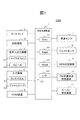
- FIG. 1 is a diagram illustrating a schematic configuration of the vehicle-mounted device 100 according to the present embodiment.
- the vehicle-mounted device 100 can be realized by, for example, a vehicle-mounted navigation device having a navigation function.
- the navigation function is a function provided in a normal navigation device such as display of map information, search and guidance of a recommended route from the departure place (or current location) to the destination, and display of traffic information.
- In-vehicle device 100 is not limited to a navigation device, and may be, for example, a smartphone, a tablet terminal device, a PDA (Personal Data Assistance), or the like.
- the navigation function is provided by an application installed in these devices or a server device to which these devices can be connected.
- the vehicle-mounted device 100 includes an arithmetic processing device 1, a display 2, a storage device 3, a voice input / output device 4 (a microphone 41 as a voice input device, and a speaker 42 as a voice output device). ), Input device 5, ROM (Read Only Memory) device 6, vehicle speed sensor 7, gyro sensor 8, GPS (Global Positioning System) receiver 9, FM multiplex broadcast receiver 10, and beacon receiver 11.
- the arithmetic processing device 1 is a central unit that performs various processes of the vehicle-mounted device 100.
- the arithmetic processing device 1 detects the current location using, for example, various sensors such as the vehicle speed sensor 7 and information output from the GPS receiver 9.
- the arithmetic processing device 1 reads map information necessary for display from the storage device 3 or the ROM device 6 based on the obtained current location information. Further, the arithmetic processing device 1 develops the read map information in graphics, and outputs a signal to be displayed on the display 2 with a mark indicating the current location superimposed thereon.
- the arithmetic processing device 1 calculates a recommended route that connects the starting point and the destination pointed by the user using the map information stored in the storage device 3 or the ROM device 6. In addition, the arithmetic processing device 1 outputs a predetermined signal to the speaker 42 and the display 2 to guide the route.
- the arithmetic processing device 1 sets a divided area obtained by dividing the display area at a predetermined ratio. In addition, the arithmetic processing device 1 displays predetermined display information corresponding to the layout of the divided areas in each divided area in a predetermined display form.
- Such an arithmetic processing device 1 includes a CPU (Central Processing Unit) 21 that executes various processes such as numerical calculation and control of each device, and map information and arithmetic data read from a memory device such as the storage device 3 or the ROM 23.
- a RAM (Random Access Memory) 22 that temporarily stores data
- a ROM 23 that stores a boot program realized by the CPU 21, an I / F (interface) 24 for connecting various hardware to the arithmetic processing unit 1, and the like
- a bus 25 for connecting them to each other.
- Display 2 is a unit that displays graphics information.
- the display 2 is composed of, for example, a liquid crystal display or an organic EL display.
- the storage device 3 includes at least a readable / writable storage medium such as an HDD (Hard Disk Drive) or a nonvolatile memory card.
- the storage device 3 stores, for example, various information (for example, map information and display rule information) used by the arithmetic processing device 1. Details of the display rule information will be described later.
- the voice input / output device 4 includes a microphone 41 as a voice input device and a speaker 42 as a voice output device.
- the microphone 41 acquires sound outside the in-vehicle device 100 such as a voice (user utterance) uttered by a driver or a passenger.
- the speaker 42 outputs a guidance to the driver or the like generated by the arithmetic processing device 1 as a voice.
- the input device 5 is a device that receives an instruction input from a user.
- the input device 5 includes a touch panel 51, a dial switch 52, scroll keys that are other hard switches, and the like (not shown).
- the input device 5 outputs information corresponding to the operation of each key or each switch to other devices such as the arithmetic processing device 1.
- the touch panel 51 is mounted on the display surface side of the display 2 and is the input device 5 mounted so that the display screen can be seen through.
- the touch panel 51 detects a touch with a human finger or a touch with a dedicated touch pen.
- the touch position by the user is specified based on the XY coordinates set on the touch panel 51, for example.
- Such a touch panel 51 is configured by, for example, an input detection element using a capacitance method.
- the ROM device 6 includes at least a readable storage medium such as a ROM such as a CD (Compact Disk) -ROM or a DVD (Digital Versatile Disk) -ROM, or an IC (Integrated Circuit) card.
- a readable storage medium such as a CD (Compact Disk) -ROM or a DVD (Digital Versatile Disk) -ROM, or an IC (Integrated Circuit) card.
- a readable storage medium such as a ROM such as a CD (Compact Disk) -ROM or a DVD (Digital Versatile Disk) -ROM, or an IC (Integrated Circuit) card.
- a readable storage medium such as a ROM such as a CD (Compact Disk) -ROM or a DVD (Digital Versatile Disk) -ROM, or an IC (Integrated Circuit) card.
- moving image data, audio data, and the like are stored.
- the vehicle speed sensor 7 is a sensor that outputs a value used for calculating the vehicle speed.
- the gyro sensor 8 is configured by an optical fiber gyro, a vibration gyro, or the like, and is a sensor that detects an angular velocity due to rotation of a moving body.
- the GPS receiver 9 receives a signal from a GPS satellite and measures the distance between the mobile body and the GPS satellite and the rate of change of the distance with respect to three or more satellites to thereby determine the current location, travel speed, and travel of the mobile body. It measures the direction. Each of these devices is used in the arithmetic processing device 1 to detect the current location of the vehicle on which the vehicle-mounted device 100 is mounted.
- the FM multiplex broadcast receiver 10 receives an FM multiplex broadcast signal sent from an FM broadcast station.
- FM multiplex broadcasting includes VICS information outline current traffic information, regulation information, SA / PA (service area / parking area) information, parking lot information, weather information, text information provided by radio stations as FM multiplex general information, and the like. include.
- the beacon receiving device 11 receives rough current traffic information such as VICS information, regulation information, SA / PA (service area / parking area) information, parking lot information, weather information, emergency alerts, and the like.
- the beacon receiving device 11 includes, for example, an optical beacon that communicates by light and a radio beacon that communicates by radio waves.
- the hardware configuration of the vehicle-mounted device 100 has been described above.
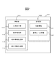
- FIG. 2 is a diagram illustrating an example of functional blocks of the vehicle-mounted device 100.
- the vehicle-mounted device 100 includes a calculation unit 101 and a storage unit 102.
- the calculation unit 101 includes an input reception unit 111, an operation detection unit 112, a display area setting unit 113, and a display information generation unit 114.
- the input receiving unit 111 is a functional unit that receives an instruction and information input from the user via the input device 5 (in this case, the dial switch 52 and other hard switches) included in the vehicle-mounted device 100. For example, the input receiving unit 111 receives a setting of a departure place and a destination, a search instruction for a recommended route, and the like from the user via the input device 5.
- the operation detection unit 112 is a functional unit that detects an operation on the touch panel 51 with a user's finger or a dedicated touch pen. Specifically, the operation detection unit 112 detects a touch on the touch panel 51, an operation for changing the touch position while continuing the touch (hereinafter referred to as a drag operation), and a touch release. In addition, the operation detection unit 112 specifies the coordinate position on the touch panel 51 that is touched and the coordinate position where the touch is released.
- the operation detection unit 112 detects an operation (for example, a flick operation or a swipe operation) of moving the touch position on the touch panel 51 in a certain direction, up, down, left, or right, and specifies the operation direction (the direction of the flick operation or the swipe operation).
- the flick operation here refers to an operation of releasing the touch from the touch panel 51 while sliding the touch position on the touch panel 51 in a certain direction.
- the swipe operation refers to an operation of sliding the touch position on the touch panel 51 in a certain direction.
- a flick operation may be a swipe operation instead of a flick operation.
- the operation detection unit 112 detects a plurality of touches (for example, twice) (hereinafter referred to as a double tap operation) on the touch panel 51 within a predetermined time (for example, 0.5 seconds), and determines each touch position.
- a predetermined time for example, 0.5 seconds
- the operation detection unit 112 detects the type of the touch operation, the coordinate position being touched, the coordinate position where the touch is released, the direction of the flick operation, and the double tap operation. A signal that associates the coordinates of each touch position is generated and output to the display area setting unit 113.
- the display area setting unit 113 is a functional unit that sets a display area. Specifically, the display area setting unit 113 sets the entire screen area with the entire display area as one display area or a divided area obtained by dividing the entire screen area into a predetermined number (for example, four) of display areas.
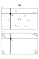
- FIG. 3 is a diagram showing a layout of divided areas.
- a divided area A (hereinafter referred to as “3/4 screen”) that occupies 3/4 of the entire screen is set at the lower right position.
- the 3/4 screen has a similar shape of the entire screen area in which the ratio of the long side to the short side is configured at a ratio of 16: 9. The ratio is configured at a ratio of 16: 9.
- a divided area B (hereinafter referred to as “child horizontal screen”) and a divided area C (hereinafter referred to as “child vertical screen”).
- the divided area D (hereinafter referred to as “child small screen”) is set.
- numerical values such as the ratio of the long side and the short side (16: 9) and the occupied area (3/4) are not strict meanings, but include a range in which they can be viewed as substantially the same.
- Layout 2 3/4 screen is set at the lower left position. In layout 3, the 3/4 screen is set at the upper left position. In layout 4, the 3/4 screen is set at the upper right position.
- the sizes and ratios of the divided areas A to D related to the layouts 2 to 4 are the same as those of the layout 1.
- the display area setting unit 113 changes the layout of the display area based on the signal output from the operation detection unit 112. For example, a case where a touch operation on the pointer is performed in a state where the divided area of the layout 1 is displayed will be described.
- the operation detection unit 112 When detecting that the user has performed a drag operation while touching the pointer, the operation detection unit 112 detects the coordinate position of the pointer on the touch panel 51 and associates it with the type of touch operation (in this case, the drag operation). The signal is output to the display area setting unit 113 periodically (for example, every 0.1 second). Further, when detecting that the touch is released, the operation detection unit 112 outputs a signal in which the coordinate position and the type of the touch operation (in this case, the touch release) are associated with each other to the display area setting unit 113. When such a signal is acquired, the display area setting unit 113 identifies which area the touch release position is set on the touch panel 51 and determines the layout of the divided areas.
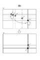
- FIG. 4A shows an example of the touch release detection areas O to R and the touch release position.
- the display area setting unit 113 sets the touch release detection areas O to R on the display 2. Such an area is an area divided into four equal parts by connecting the midpoints of the long side and the short side of the entire display area.
- the display area setting unit 113 sets the divided area of the layout 2.
- the display area setting unit 113 sets a divided area of the layout 3.
- the display area setting unit 113 sets a divided area of the layout 3.
- the display area setting unit 113 sets a divided area of the layout 3.
- the display area setting unit 113 sets a divided area of the layout 1.
- FIG. 4B is a diagram showing an example of touch release detection areas E1 to E4 and touch release positions F1 to F4.
- the display area setting unit 113 sets the touch release areas E1 to E4 on the display 2 simultaneously with the setting of the touch release detection areas O to R. Such an area is a quadrant area including the apexes of the four corners of the display area.
- the display area setting unit 113 sets the full screen area as the display area.
- the display area setting unit 113 outputs a signal indicating the coordinates of the touch release position to the display information generation unit 114.
- the display area setting unit 113 temporarily sets a freely variable divided area while the pointer is moving, and outputs a display instruction to the display information generation unit 114.
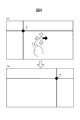
- FIG. 5A shows the movement of the pointer and the shape change of the divided areas.
- the display area setting unit 113 uses the coordinate position of the pointer periodically acquired from the operation detection unit 112 as an intersection 4. A divided area is temporarily set.
- the display area setting unit 113 outputs a display instruction for such divided areas to the display information generation unit 114. Thereby, while the pointer is moving, a divided region whose shape changes according to the pointer position N is displayed.
- FIG. 5B is a diagram illustrating changes in the pointer position N and the divided areas before and after the touch release.
- the operation detection unit 112 when detecting that the user performs a flick operation on the touch panel 51, the operation detection unit 112 specifies the type of the touch operation (in this case, the flick operation) and the direction of the flick operation, and associates these signals. Is output to the display area setting unit 113.
- the display area setting unit 113 determines the layout of the divided areas based on the direction of the flick operation.
- FIG. 6A shows the direction of the flick operation (or swipe operation).
- the display area setting unit 113 specifies the layout of the current divided area. For example, when the divided area of the layout 1 is displayed, the display area setting unit 113 specifies the layout of the divided area in which the pointer is translated in the right direction. That is, the display area setting unit 113 specifies the layout 2 and sets a divided area according to the layout.
- FIG. 6B is a diagram showing the layout of the divided areas changed based on the direction of the flick operation (or swipe operation).
- the display area setting unit 113 specifies the layout of the divided area in which the pointer is translated downward. To do. That is, the display area setting unit 113 specifies the layout 3 and sets a divided area according to the layout.
- the operation detection unit 112 when detecting that the user has double-tapped any one of the four corners of the display area, specifies the coordinates on the touch panel 51 indicating each touch position, and determines the type of touch operation (this In this case, a signal in which a double tap operation) is associated with each coordinate position is transmitted to the display area setting unit 113.
- the display area setting unit 113 sets the entire screen area when the coordinates of each touch position by the double tap operation are included in any one of the four corners of the display area.
- the display area setting unit 113 outputs a signal indicating the touched coordinate position to the display information generation unit 114.
- the display information generation unit 114 is a functional unit that generates display information to be displayed in the display area. Specifically, the display information generation unit 114 specifies display information and a display form using the display rule information, and displays the display information according to the specified display form.
- the display rule information includes the type and items of display information for each type of divided area (“full screen area”, “3/4 screen”, “child horizontal screen”, “child vertical screen”, and “child small screen”). This is information in which the display form of each item is associated.
- the types of display information include, for example, display information related to navigation, display information related to audio, display information related to tools, and display information related to APP (application content).
- the items When the type of display information is navigation, the items include guidance information such as maps, menus, navigation settings, right / left turn information (arrows), and intersection names.
- the type of display information When the type of display information is audio, the item includes each source, video, each source reproduction information, basic operation buttons, and the like.
- the type of display information is APP, items include a launcher, each application, a fixed application, a launcher call button, and the like.
- the type of display information When the type of display information is a tool, the items include a clock, various indicators, various setting buttons, a custom button, and the like.
- the display information generation unit 114 selects one divided area from among the four divided areas and specifies the type of the divided area. For example, when the upper right divided area of the layout 1 is selected, the display information generation unit 114 specifies that the divided area is a child horizontal screen.
- the display information generation unit 114 specifies the type of display information associated with the selected divided area. For example, the display information generation unit 114 acquires predetermined information (not shown) including the correspondence between the position of each divided region and the type of display information from the storage unit, and corresponds to each divided region based on such information. Specify the type of display information attached.
- the display information generation unit 114 specifies the items and display form of the display information to be displayed in each divided area using the display rule information. Specifically, the display information generation unit 114 specifies the display information item and the display form from the display rule information based on the specified type of the divided area and the type of display information, and displays the display information in the divided area.
- the display information generation unit 114 specifies display information and display form for all the divided areas of the set layout, and displays the information in each divided area.
- FIG. 7 (a), 7 (b), 8 (a), and 8 (b) are diagrams showing display information displayed in different display forms for each type of divided area.
- audio is associated with the divided area located in the upper right as the type of display information.
- the display information items include text information, music playback progress bar, album jacket, playback time, music operation button, list call button, and the like. More display information is displayed as compared to other divided area types.
- the display information generation unit 114 specifies the touch release position or the coordinate position where the double tap operation is performed based on the signal acquired from the display area setting unit 113.
- the display area setting unit 113 acquires predetermined information (not shown) including the correspondence between the identified coordinate position and the type of display information from the storage unit, and displays the predetermined information on the entire screen area based on the information. Specify the type of display information.
- the display information generation unit 114 uses the display rule information to specify items and display forms of display information to be displayed in the full screen area, and displays the display information in the specified display form.
- the storage unit 102 is a functional unit that stores predetermined information. Specifically, the storage unit 102 stores map information 121, display rule information 122, and various information not shown.
- the input reception part 111 of the onboard equipment 100, the operation detection part 112, the display area setting part 113, and the display information generation part 114 are implement
- This program is stored in the ROM 23 or the storage device 3 of the vehicle-mounted device 100, loaded on the RAM 22 for execution, and executed by the CPU 21.
- each functional block is classified according to main processing contents in order to facilitate understanding of the functions of the vehicle-mounted device 100 realized in the present embodiment. Therefore, the present invention is not limited by the classification method of each function or its name. Moreover, each structure of the onboard equipment 100 can also be classified into many more components according to the processing content. Moreover, it can also classify
- each functional unit may be constructed by hardware (an integrated circuit such as an ASIC) mounted on a computer. Further, the processing of each functional unit may be executed by one hardware, or may be executed by a plurality of hardware.
- the storage unit 102 of the vehicle-mounted device 100 is realized by the ROM 23 and the storage device 3.
- FIG. 9 is a flowchart showing the flow of the display area dividing process. Such processing is started when the vehicle-mounted device 100 is activated.
- the operation detection unit 112 determines whether or not a touch operation has been received from the user (step S001). If not received (No in step S001), the operation detection unit 112 repeatedly executes the process in step S001. On the other hand, when the operation on the touch panel 51 is received (Yes in step S001), the operation detection unit 112 moves the process to step S002.
- the operation detection unit 112 identifies the type of touch operation (step S002). For example, if it is specified that the operation is a touch and drag operation on the pointer, the operation detection unit 112 detects the coordinate position of the pointer on the touch panel 51 and associates it with the type of touch operation (in this case, touch and drag operation). The signal is output to the display area setting unit 113 periodically (for example, every 0.1 second). Further, when the operation detection unit 112 detects that the touch is released, the operation detection unit 112 outputs a signal in which the type of the touch operation (in this case, the release of the touch) and the coordinate position are associated with each other to the display area setting unit 113.
- the type of the touch operation in this case, the release of the touch
- the display area setting unit 113 sets a divided area or a full screen area (step S003). For example, when a signal indicating the coordinate position where the touch is released is acquired from the operation detection unit 112, the display area setting unit 113 detects the touch release detection areas (O, P, Q, R, E1 to E4) based on the coordinate position. Any one). For example, when the coordinate position where the touch is released is any one of the touch release detection areas O, P, Q, and R, the display area setting unit 113 determines the layout of the divided areas and the divided areas according to the layouts. Set.
- the display information generation unit 114 specifies display information and a display form (step S004). For example, the display information generation unit 114 identifies the type of each divided area set by the display area setting unit 113. Also, predetermined information (not shown) including the correspondence between the position of each divided area and the type of display information is acquired from the storage unit 102, and each divided area is based on the type of divided area and the type of display information. Items of display information to be displayed and a display form are specified from the display rule information.
- the display information generation unit 114 generates display information in the specified display form (step S005) and displays it in each divided area (step S006). In addition, the display information generation unit 114 shifts the process to step S001, and repeatedly executes the processes of steps S001 to S006.
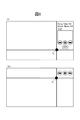
- FIGS. 10 (a) and 11 (a) are diagrams showing an example of display information displayed in each divided area and a pointer drag operation and a flick operation (or swipe operation).
- FIGS. 10B and 11B are diagrams showing an example of the layout of the divided areas changed by the drag operation and the flick operation (or swipe operation) and the display information displayed in the changed divided areas. is there.
- the vehicle-mounted device 100 when the layout of the divided areas is changed, display information suitable for the size and shape of each divided area is easier to see. Can be displayed.
- a divided region related to one layout is applied from among layouts prepared in advance based on the position where the touch on the pointer is released and the direction of the flick operation. This eliminates the need to finely set the size and shape of the divided areas. That is, the operation burden on the user can be reduced as compared with the case where the size and shape of the divided region are freely variable by the user.
- the divided areas are set according to a predetermined layout. For this reason, the processing load of the CPU 21 can be reduced as compared with the case where the setting of the divided areas is freely variable by the user.
- the vehicle-mounted device 100 can change and display the number and contents of items to be displayed for each type of display information according to the change in the layout of the display area.
- the display information generation unit 114 uses the display rule information 122 to identify items of display information corresponding to the shape type of the display area, so that the number of items to be displayed and the number of items to be displayed for each type of display information are displayed. Identify and display the contents.
- FIG. 12 is a diagram showing an example of the display rule information 122.
- the display rule information 122 is information in which the type of display information is associated with the item for each shape type of the display area.
- the display rule information 122 includes, for each shape type 123 of the display area, navigation (NAVI) 124, audio (AUDIO) 125, application content (APP) 126, and tool (TOOL) 127, which are types of display information. It has a table in which items related to are associated.
- the display area shape type 123 is information indicating a layout type of the display area, and includes a full screen, a 3/4 screen, a horizontal screen (horizontal band screen), a vertical screen (vertical band screen), There is a child small screen (small screen).
- Items 124 to 127 of each type of display information are information indicating items to be displayed in the display area (divided area).
- the NAVI item 124 associated with the full screen and the 3/4 screen includes a map, a menu, and a navigation setting.
- the NAVI item 124 associated with the child horizontal screen and the child vertical screen includes right / left turn information, intersection name, remaining distance, and the like as guidance information.
- the NAVI item 124 associated with the small child screen includes guidance information such as right / left turn information and a remaining distance.
- the APP item 126 associated with the full screen and the 3/4 screen includes a launcher and each application.
- the APP item 126 associated with the child horizontal screen and the child vertical screen includes a fixed application (dedicated screen) and a launcher call button.
- the shape type of the large display area (for example, full screen and 3/4 screen) is larger than the shape type of the small display area (for example, horizontal screen). Items are associated with each other, or items that require a relatively wide display area (for example, a map or a launcher) are associated with each other.
- the display information generation unit 114 specifies items to be displayed in the display area (each divided area) using such display rule information 122.
- FIG. 13 is a diagram showing the layout change of the display area when the display area is flicked with two fingers.
- the operation detection unit 112 detects that the user performs a flick operation with one finger on a predetermined coordinate on the touch panel 51 displaying the map information
- the operation detection unit 112 associates the coordinate position with the direction of the flick operation.
- the attached signal is transmitted to the display information generation unit 114.
- the display information generation unit 114 acquires the signal
- the display information generation unit 114 generates screen information obtained by scrolling the map information in the direction of the flick operation, and displays the screen information on the display 2.
- the display information generation unit 114 changes the layout of the display area regardless of the position where the finger is released.
- the onboard equipment 100 can distinguish between the scrolling of the map by the flick operation of one finger and the layout change of the display area by the flick operation of two fingers, thereby improving the operability for the user and the convenience of the onboard equipment 100. Can be made.
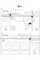
- FIG. 14 is a diagram showing an example of display contents that change in accordance with a change in the layout of (b) from the layout of (a).
- the shape type of the display area 130 of the NAVI in the layout (a) before the change is a child vertical screen.
- the display information generation unit 114 displays the left / right turn information and the remaining distance as guidance information based on the display rule information 122.
- the display information generation unit 114 creates a map that can be displayed in a wide display area based on the display rule information 122. Menus and navigation settings are displayed.
- the shape type of the APP display area 131 in the layout (a) before the change is 3/4 screen.
- the display information generation unit 114 displays a launcher, each application, and the like based on the display rule information 122. Further, when the shape type of the APP display area 131 becomes a child vertical screen due to the change to the layout of (b), the display information generation unit 114 is based on the display rule information 122 and the launcher that is easy for the user to visually recognize even in a small display area. Displays a call button.
- the shape type of the TOOL display area 132 in the layout (a) before the change is a horizontal screen.
- the display information generation unit 114 displays a clock, various indicators, and the like based on the display rule information 122.
- the display information generation unit 114 determines a predetermined number (books) corresponding to the small display area. In the example, one icon and a predetermined type (phone in this example) are displayed.
- the shape type of the AUDIO display area 133 in the layout (a) before the change is a small child screen.
- the display information generation unit 114 displays basic operation buttons based on the display rule information 122.
- the display information generation unit 114 displays a display area wider than the small child screen based on the display rule information 122. Displays each possible source playback information and basic operation buttons.
- the display rule information 122 by using the display rule information 122, the number and contents of items to be displayed are changed for each type of display information according to the change in the layout of the display area. Can be displayed. For example, if a large number of items (items) are displayed in a relatively small display area, it is difficult for the user to visually recognize the item. In the vehicle-mounted device 100 according to the present invention, such a situation can be prevented by using the display rule information 122 described above.
- the display rule information 122 it is possible to control the display and non-display of icons that are objects that can be touched in accordance with the change in the layout of the display area. For example, if a large number of icons are to be displayed in a relatively small display area, the size of the icon becomes small and the user cannot easily press it. In particular, since it is difficult for a user who is driving a vehicle to view an icon for a long time, a small-size icon is more difficult to press. In the vehicle-mounted device 100 according to the present invention, by using the display rule information 122 described above, it is possible to prevent such a situation by displaying an appropriate number or form of icons according to the size of the display area. .
- the display information generation unit 114 When the display information generation unit 114 receives a touch on an item or icon displayed in the display area, the display information generation unit 114 specifies the display information displayed in the display area according to the type of the touched item or icon. Change to predetermined display information. For example, in the case where an icon indicating that music or the like is “playing” is displayed in the display area related to audio, when a touch on the icon is received, the display information generation unit 114 displays the touched icon as “ Change to an icon that indicates "stopped”. Further, for example, when receiving a touch on an icon indicating a predetermined application displayed in the display area related to the APP, the display information generation unit 114 displays screen information corresponding to the application of the touched icon (for example, a phone application is touched). If a call is made, a call history and a numeric keypad for entering a phone number are displayed.
- the present invention is not limited to the above-described embodiment, and various embodiments and modifications are included besides these.
- the above embodiment has been described in detail for easy understanding of the present invention, and is not necessarily limited to the one having all the configurations described.
- a part of the configuration of an embodiment can be replaced with the configuration of another embodiment or a modification, and the configuration of another embodiment can be added to the configuration of a certain embodiment.
- each or all of the above-described configurations, functions, processing units, processing means, and the like may be realized by a program in which the processor realizes each function.
- Information such as programs, tables, and files for realizing each function is stored in a memory, a storage device such as a hard disk or SSD (Solid State Drive), or a recording medium such as an IC card, SD (Secure Digital) memory card, or DVD.
- a storage device such as a hard disk or SSD (Solid State Drive), or a recording medium such as an IC card, SD (Secure Digital) memory card, or DVD.
- the control lines and information lines are those that are considered necessary for the explanation, and not all control lines and information lines on the product are necessarily shown.
- DESCRIPTION OF SYMBOLS 100 ... Onboard equipment, 1 ... Arithmetic processing device, 2 ... Display, 3 ... Memory
Abstract
Description
次に、車載器100で実行される表示領域分割処理について説明する。図9は、表示領域分割処理の流れを示したフロー図である。かかる処理は、車載器100の起動と共に開始される。 [Description of operation]
Next, the display area dividing process executed by the vehicle-mounted
5・・・入力装置、51・・・タッチパネル、52・・・ダイヤルスイッチ、
6・・・ROM装置、7・・・車速センサ、8・・・ジャイロセンサ、
9・・・GPS受信装置、10・・・FM多重放送受信装置、
11・・・ビーコン受信装置、101・・・演算部、102・・・記憶部、
111・・・入力受付部、112・・・操作検知部、113・・・表示領域設定部、
114・・・表示情報生成部、121・・・地図情報、122・・・表示ルール情報 DESCRIPTION OF
5 ... input device, 51 ... touch panel, 52 ... dial switch,
6 ... ROM device, 7 ... vehicle speed sensor, 8 ... gyro sensor,
9 ... GPS receiver, 10 ... FM multiplex broadcast receiver,
11 ... beacon receiving device, 101 ... arithmetic unit, 102 ... storage unit,
111... Input reception unit, 112... Operation detection unit, 113.
114: Display information generation unit, 121: Map information, 122: Display rule information
Claims (13)
- 表示領域を備えた表示部を有する車載器であって、
タッチパネルの操作を検知する操作検知部と、
検知された操作に基づき、表示領域を分割した分割領域に関する所定のレイアウトの中から1つのレイアウトを特定し、特定した該レイアウトに従って前記分割領域を設定する分割領域設定部と、
前記分割領域の設定位置に対応付けられた表示情報の種類と前記分割領域の形状タイプとに基づいて、前記表示情報の項目および表示形態を各分割領域ごとに特定し、特定した前記表示形態により前記表示情報を対応する前記分割領域に表示する表示情報生成部と、を有する
ことを特徴とする車載器。 An in-vehicle device having a display unit with a display area,
An operation detection unit for detecting operation of the touch panel;
Based on the detected operation, a divided area setting unit that identifies one layout from a predetermined layout related to the divided area obtained by dividing the display area, and sets the divided area according to the identified layout;
Based on the type of display information associated with the setting position of the divided area and the shape type of the divided area, the display information item and the display form are specified for each divided area, and the specified display form A vehicle-mounted device comprising: a display information generation unit configured to display the display information in the corresponding divided region. - 請求項1に記載の車載器であって、
前記分割領域設定部は、
前記操作検知部により検知された操作の解除位置に基づき、前記分割領域のレイアウトを特定する
ことを特徴とする車載器。 The vehicle-mounted device according to claim 1,
The divided area setting unit includes:
The vehicle-mounted device characterized by specifying the layout of the divided regions based on the operation release position detected by the operation detection unit. - 請求項1に記載の車載器であって、
前記分割領域設定部は、
前記操作検知部により検知された前記タッチパネル上の操作方向に基づき、前記分割領域のレイアウトを特定する
ことを特徴とする車載器。 The vehicle-mounted device according to claim 1,
The divided area setting unit includes:
The vehicle-mounted device characterized by specifying a layout of the divided area based on an operation direction on the touch panel detected by the operation detection unit. - 請求項1に記載の車載器であって、
前記分割領域設定部は、
前記操作検知部により検知された操作の解除位置または
タッチ位置とタッチ回数と、に基づいて、画面全体を1つの表示領域とした全画面領域を設定し、
前記表示情報生成部は、
前記操作の解除位置または前記タッチ位置に対応付けられた前記表示情報の種類と、前記表示領域の形状タイプとに基づいて、前記表示情報の項目および表示形態を特定し、
特定した前記表示形態により前記表示情報を表示する
ことを特徴とする車載器。 The vehicle-mounted device according to claim 1,
The divided area setting unit includes:
Based on the release position or touch position of the operation detected by the operation detection unit and the number of touches, a full screen area is set with the entire screen as one display area,
The display information generation unit
Based on the type of the display information associated with the release position of the operation or the touch position and the shape type of the display area, the display information item and the display form are identified,
The in-vehicle device, wherein the display information is displayed according to the specified display form. - 請求項1に記載の車載器であって、
前記分割領域のレイアウトは、
前記表示領域全体の相似形であって、前記表示領域全体の略3/4の面積を占める分割領域と、
前記相似形の分割領域を区画する長辺および短辺を延長して形成される複数の分割領域とにより構成されている
ことを特徴とする車載器。 The vehicle-mounted device according to claim 1,
The layout of the divided areas is as follows:
A divided area that is similar to the entire display area and occupies approximately 3/4 of the entire display area;
A vehicle-mounted device comprising a plurality of divided regions formed by extending a long side and a short side that partition the similar divided region. - 表示領域を備えた表示部を有する車載器により実行される表示領域分割方法であって、
前記車載器は、
タッチパネルの操作を検知する検知ステップと、
検知された操作に基づき、表示領域を分割した分割領域に関する所定のレイアウトの中から1つのレイアウトを特定し、特定した前記レイアウトに従って該分割領域を設定する分割領域設定ステップと、
前記分割領域の設定位置に対応付けられた表示情報の種類と前記分割領域の形状タイプとに基づいて、前記表示情報の項目および表示形態を各分割領域ごとに特定し、特定した前記表示形態により前記表示情報を対応する前記分割領域に表示する表示ステップと、行う
ことを特徴とする表示領域分割方法。 A display area dividing method executed by an in-vehicle device having a display unit with a display area,
The in-vehicle device is
A detection step for detecting a touch panel operation;
A divided region setting step of identifying one layout from predetermined layouts related to the divided region obtained by dividing the display region based on the detected operation, and setting the divided region according to the identified layout;
Based on the type of display information associated with the setting position of the divided area and the shape type of the divided area, the display information item and the display form are specified for each divided area, and the specified display form A display step of displaying the display information in the corresponding divided area; and a display area dividing method comprising: - コンピュータを、表示領域を備えた表示部を有する車載器として機能させるプログラムであって、
前記コンピュータを、
タッチパネルの操作を検知する操作検知部と、
検知された操作に基づき、表示領域を分割した分割領域に関する所定のレイアウトの中から1つのレイアウトを特定し、特定した前記レイアウトに従って該分割領域を設定する分割領域設定部と、
前記分割領域の設定位置に対応付けられた表示情報の種類と前記分割領域の形状タイプとに基づいて、前記表示情報の項目および表示形態を各分割領域ごとに特定し、特定した前記表示形態により前記表示情報を対応する前記分割領域に表示する表示情報生成部として機能させる
ことを特徴とするプログラム。 A program for causing a computer to function as a vehicle-mounted device having a display unit with a display area,
The computer,
An operation detection unit for detecting operation of the touch panel;
Based on the detected operation, a divided area setting unit that identifies one layout from predetermined layouts related to the divided areas obtained by dividing the display area, and sets the divided areas according to the identified layout;
Based on the type of display information associated with the setting position of the divided area and the shape type of the divided area, the display information item and the display form are specified for each divided area, and the specified display form A program that causes the display information to function as a display information generation unit that displays the display information in the corresponding divided area. - 第1の情報を表示する第1の表示領域と第2の情報を表示する第2の表示領域とを含む表示領域のレイアウトを複数種類記憶する記憶部と、
前記第1の表示領域で表示される第1の情報と、前記第2の表示領域で表示される第2の情報と、を決定する制御部と、を備え、
前記制御部は、
タッチパネルへの接触が解除された位置に基づいて、前記複数種類のレイアウトのうちの何れかを選択することを特徴とする情報制御装置。 A storage unit for storing a plurality of types of layouts of a display area including a first display area for displaying first information and a second display area for displaying second information;
A controller that determines first information displayed in the first display area and second information displayed in the second display area;
The controller is
An information control apparatus, wherein one of the plurality of types of layouts is selected based on a position where contact with the touch panel is released. - 請求項8に記載の情報制御装置であって、
前記制御部は、
前記タッチパネルへの接触が解除された位置が前記第1の表示領域内のとき、第1の前記レイアウトを選択し、
前記タッチパネルへの接触が解除された位置が前記第2の表示領域内のとき、第2の前記レイアウトを選択する
ことを特徴とする情報制御装置。 The information control apparatus according to claim 8, wherein
The controller is
When the position where the touch on the touch panel is released is within the first display area, the first layout is selected,
2. The information control apparatus according to claim 1, wherein the second layout is selected when the position where the touch on the touch panel is released is within the second display area. - 請求項8または9に記載の情報制御装置であって、
前記制御部は、
前記タッチパネルへの接触が解除されたとき、当該解除位置に応じて、一の表示領域と他の表示領域とを区画する区画線および当該区画線同士の交点を前記レイアウトに従って所定位置に移動させる
ことを特徴とする情報制御装置。 The information control device according to claim 8 or 9, wherein
The controller is
When the touch to the touch panel is released, according to the release position, the dividing line that divides one display area and the other display area and the intersection of the dividing lines are moved to a predetermined position according to the layout. An information control device. - 請求項8~10のいずれか一項に記載の情報制御装置であって、
前記制御部は、
第1の態様で前記タッチパネルへの接触が行われると、当該タッチパネルへの接触が解除された位置に基づいて前記複数種類のレイアウトのうちの何れかを選択し、
第2の態様で前記タッチパネルへの接触が行われると、当該タッチパネルへの接触が行われた位置と当該接触が解除された位置とによって特定される方向に基づき、前記複数種類のレイアウトのうちの何れかを選択する
ことを特徴とする情報制御装置。 The information control device according to any one of claims 8 to 10,
The controller is
When the touch to the touch panel is performed in the first aspect, one of the plurality of types of layouts is selected based on the position where the touch to the touch panel is released,
When the touch to the touch panel is performed in the second aspect, based on the direction specified by the position where the touch is made and the position where the contact is released, An information control apparatus that selects any one of them. - 請求項8~11のいずれか一項に記載の情報制御装置であって、
前記制御部は、
前記第1のレイアウトが選択されているときに前記第1の表示領域で表示する前記第1の情報に含まれる表示項目と、前記第2のレイアウトが選択されているときに前記第1の表示領域で表示する前記第1の情報に含まれる表示項目とを異ならせて表示する
ことを特徴とする情報制御装置。 The information control device according to any one of claims 8 to 11,
The controller is
Display items included in the first information displayed in the first display area when the first layout is selected, and the first display when the second layout is selected. An information control apparatus, characterized in that a display item included in the first information displayed in an area is displayed differently. - 請求項12に記載の情報制御装置であって、
前記制御部は、
前記表示項目への接触が行われると、前記第1の表示領域に表示された前記第1の情報の表示を変更する
ことを特徴とする情報制御装置。 An information control apparatus according to claim 12, wherein
The controller is
The information control apparatus according to claim 1, wherein when the display item is touched, the display of the first information displayed in the first display area is changed.
Priority Applications (4)
| Application Number | Priority Date | Filing Date | Title |
|---|---|---|---|
| US16/064,601 US10936188B2 (en) | 2015-12-22 | 2016-12-22 | In-vehicle device, display area splitting method, program, and information control device |
| EP16878961.8A EP3396514B1 (en) | 2015-12-22 | 2016-12-22 | Display area dividing device, method and computer program |
| CN201680074771.2A CN108431757B (en) | 2015-12-22 | 2016-12-22 | Vehicle-mounted device, display area segmentation method and computer-readable storage medium |
| JP2017558281A JP6838563B2 (en) | 2015-12-22 | 2016-12-22 | On-board unit, display area division method, program and information control device |
Applications Claiming Priority (2)
| Application Number | Priority Date | Filing Date | Title |
|---|---|---|---|
| JP2015-249794 | 2015-12-22 | ||
| JP2015249794 | 2015-12-22 |
Publications (1)
| Publication Number | Publication Date |
|---|---|
| WO2017111075A1 true WO2017111075A1 (en) | 2017-06-29 |
Family
ID=59090500
Family Applications (1)
| Application Number | Title | Priority Date | Filing Date |
|---|---|---|---|
| PCT/JP2016/088474 WO2017111075A1 (en) | 2015-12-22 | 2016-12-22 | On-board device, display area dividing method, program, and information control device |
Country Status (5)
| Country | Link |
|---|---|
| US (1) | US10936188B2 (en) |
| EP (1) | EP3396514B1 (en) |
| JP (1) | JP6838563B2 (en) |
| CN (1) | CN108431757B (en) |
| WO (1) | WO2017111075A1 (en) |
Cited By (4)
| Publication number | Priority date | Publication date | Assignee | Title |
|---|---|---|---|---|
| WO2020009046A1 (en) * | 2018-07-05 | 2020-01-09 | クラリオン株式会社 | Information control device and display modification method |
| WO2020009047A1 (en) * | 2018-07-05 | 2020-01-09 | クラリオン株式会社 | Information control device and display modification method |
| JP2020135627A (en) * | 2019-02-22 | 2020-08-31 | パイオニア株式会社 | Information display device, information display method and program |
| US11869459B2 (en) * | 2020-10-22 | 2024-01-09 | Faurecia Clarion Electronics Co., Ltd. | Display control device and display control method for controlling the display of graphic objects in dynamically changed display regions |
Families Citing this family (4)
| Publication number | Priority date | Publication date | Assignee | Title |
|---|---|---|---|---|
| JP7202876B2 (en) * | 2018-12-25 | 2023-01-12 | フォルシアクラリオン・エレクトロニクス株式会社 | Display control device and display control method |
| JP7214542B2 (en) * | 2019-04-12 | 2023-01-30 | フォルシアクラリオン・エレクトロニクス株式会社 | Display control device and display control method |
| CN114846439A (en) * | 2019-12-18 | 2022-08-02 | 佛吉亚歌乐电子有限公司 | Display control device and display control method |
| US11693545B2 (en) | 2019-12-18 | 2023-07-04 | Faurecia Clarion Electronics Co., Ltd. | Device and method for arranging objects displayed on divided areas in a vehicle display |
Citations (11)
| Publication number | Priority date | Publication date | Assignee | Title |
|---|---|---|---|---|
| JP2007034456A (en) * | 2005-07-25 | 2007-02-08 | Fuji Xerox Co Ltd | Information processor and information processing program |
| JP2007257220A (en) * | 2006-03-22 | 2007-10-04 | Matsushita Electric Ind Co Ltd | Display device |
| JP2008085546A (en) * | 2006-09-27 | 2008-04-10 | Funai Electric Co Ltd | Video output device |
| JP2008227679A (en) * | 2007-03-09 | 2008-09-25 | Funai Electric Co Ltd | Television broadcast signal receiver |
| JP2009229172A (en) * | 2008-03-21 | 2009-10-08 | Alpine Electronics Inc | Information-providing system and information-providing method |
| JP2012123477A (en) * | 2010-12-06 | 2012-06-28 | Fujitsu Ten Ltd | Shortcut icon registration method |
| JP2013114266A (en) * | 2011-11-24 | 2013-06-10 | Sharp Corp | Display control device, display method, control program, and recording medium |
| JP2013228900A (en) * | 2012-04-26 | 2013-11-07 | Kyocera Document Solutions Inc | Display input device and image formation apparatus |
| JP2015041271A (en) * | 2013-08-22 | 2015-03-02 | ソニー株式会社 | Information processor, storage medium and control method |
| JP2015087861A (en) | 2013-10-29 | 2015-05-07 | 京セラ株式会社 | Electronic apparatus and control program, and operation method for electronic apparatus |
| JP2015208602A (en) * | 2014-04-30 | 2015-11-24 | 株式会社日立メディコ | Image display device and image display method |
Family Cites Families (20)
| Publication number | Priority date | Publication date | Assignee | Title |
|---|---|---|---|---|
| DE3707490A1 (en) * | 1987-03-09 | 1988-09-22 | Siemens Ag | ARRANGEMENT FOR THE SIMULTANEOUS DISPLAY OF SEVERAL IMAGES ON THE SCREEN OF A VIEWING DEVICE |
| US20020191028A1 (en) * | 2001-06-19 | 2002-12-19 | Senechalle David A. | Window manager user interface |
| CN1739086A (en) * | 2003-01-14 | 2006-02-22 | 皇家飞利浦电子股份有限公司 | Rearranging views on a computer screen |
| US7480872B1 (en) * | 2003-04-06 | 2009-01-20 | Apple Inc. | Method and apparatus for dynamically resizing windows |
| JP2005038064A (en) * | 2003-07-16 | 2005-02-10 | Fuji Electric Holdings Co Ltd | Screen layout setting program and program storage medium |
| US20050280524A1 (en) * | 2004-06-18 | 2005-12-22 | Applied Digital, Inc. | Vehicle entertainment and accessory control system |
| US7770109B2 (en) * | 2005-12-16 | 2010-08-03 | Microsoft Corporation | Adaptive layout for content |
| US7694221B2 (en) * | 2006-02-28 | 2010-04-06 | Microsoft Corporation | Choosing between multiple versions of content to optimize display |
| US7773075B2 (en) | 2006-03-22 | 2010-08-10 | Panasonic Corporation | Display apparatus |
| JP2011089820A (en) * | 2009-10-21 | 2011-05-06 | Clarion Co Ltd | Navigation device and display method therefor |
| US8208964B2 (en) * | 2009-10-30 | 2012-06-26 | Cellco Partnership | Flexible home page layout for mobile devices |
| JP4975129B2 (en) * | 2010-03-23 | 2012-07-11 | シャープ株式会社 | Operating device, electronic device and image processing apparatus including the operating device, and information display method in the operating device |
| US20120159314A1 (en) * | 2010-12-16 | 2012-06-21 | Microsoft Corporation | Adaptive content layout |
| CN102053795B (en) * | 2011-01-11 | 2012-10-24 | 华平信息技术股份有限公司 | Method and system for freely laying out video display window |
| TWI486870B (en) * | 2013-01-23 | 2015-06-01 | Acti Corp | Dynamically control how to split the window size |
| US10152459B2 (en) * | 2013-02-20 | 2018-12-11 | Google Llc | Intelligent window placement with multiple windows using high DPI screens |
| EP2796980B1 (en) * | 2013-04-26 | 2019-04-10 | Spreadtrum Communications (Shanghai) Co., Ltd. | Apparatus and method for setting a two hand mode to operate a touchscreen |
| US20150007078A1 (en) * | 2013-06-28 | 2015-01-01 | Sap Ag | Data Displays in a Tile-Based User Interface |
| KR20150007910A (en) * | 2013-07-11 | 2015-01-21 | 삼성전자주식회사 | user termincal device for supporting user interaxion and methods thereof |
| KR20150029451A (en) * | 2013-09-10 | 2015-03-18 | 엘지전자 주식회사 | Mobile terminal and method for controlling the same |
-
2016
- 2016-12-22 CN CN201680074771.2A patent/CN108431757B/en active Active
- 2016-12-22 WO PCT/JP2016/088474 patent/WO2017111075A1/en active Application Filing
- 2016-12-22 EP EP16878961.8A patent/EP3396514B1/en active Active
- 2016-12-22 JP JP2017558281A patent/JP6838563B2/en active Active
- 2016-12-22 US US16/064,601 patent/US10936188B2/en active Active
Patent Citations (11)
| Publication number | Priority date | Publication date | Assignee | Title |
|---|---|---|---|---|
| JP2007034456A (en) * | 2005-07-25 | 2007-02-08 | Fuji Xerox Co Ltd | Information processor and information processing program |
| JP2007257220A (en) * | 2006-03-22 | 2007-10-04 | Matsushita Electric Ind Co Ltd | Display device |
| JP2008085546A (en) * | 2006-09-27 | 2008-04-10 | Funai Electric Co Ltd | Video output device |
| JP2008227679A (en) * | 2007-03-09 | 2008-09-25 | Funai Electric Co Ltd | Television broadcast signal receiver |
| JP2009229172A (en) * | 2008-03-21 | 2009-10-08 | Alpine Electronics Inc | Information-providing system and information-providing method |
| JP2012123477A (en) * | 2010-12-06 | 2012-06-28 | Fujitsu Ten Ltd | Shortcut icon registration method |
| JP2013114266A (en) * | 2011-11-24 | 2013-06-10 | Sharp Corp | Display control device, display method, control program, and recording medium |
| JP2013228900A (en) * | 2012-04-26 | 2013-11-07 | Kyocera Document Solutions Inc | Display input device and image formation apparatus |
| JP2015041271A (en) * | 2013-08-22 | 2015-03-02 | ソニー株式会社 | Information processor, storage medium and control method |
| JP2015087861A (en) | 2013-10-29 | 2015-05-07 | 京セラ株式会社 | Electronic apparatus and control program, and operation method for electronic apparatus |
| JP2015208602A (en) * | 2014-04-30 | 2015-11-24 | 株式会社日立メディコ | Image display device and image display method |
Non-Patent Citations (1)
| Title |
|---|
| See also references of EP3396514A4 |
Cited By (11)
| Publication number | Priority date | Publication date | Assignee | Title |
|---|---|---|---|---|
| WO2020009046A1 (en) * | 2018-07-05 | 2020-01-09 | クラリオン株式会社 | Information control device and display modification method |
| WO2020009047A1 (en) * | 2018-07-05 | 2020-01-09 | クラリオン株式会社 | Information control device and display modification method |
| JP2020009038A (en) * | 2018-07-05 | 2020-01-16 | クラリオン株式会社 | Information control device and display changing method |
| JP2020009037A (en) * | 2018-07-05 | 2020-01-16 | クラリオン株式会社 | Information control device and display changing method |
| EP3819750A4 (en) * | 2018-07-05 | 2022-03-23 | Clarion Co., Ltd. | Information control device and display modification method |
| EP3819753A4 (en) * | 2018-07-05 | 2022-03-30 | Clarion Co., Ltd. | Information control device and display modification method |
| US11334211B2 (en) | 2018-07-05 | 2022-05-17 | Clarion Co., Ltd. | Information control device and method for changing display region sizes and positional relationships |
| JP7093690B2 (en) | 2018-07-05 | 2022-06-30 | フォルシアクラリオン・エレクトロニクス株式会社 | Information control device and display change method |
| JP7129248B2 (en) | 2018-07-05 | 2022-09-01 | フォルシアクラリオン・エレクトロニクス株式会社 | Information control device and display change method |
| JP2020135627A (en) * | 2019-02-22 | 2020-08-31 | パイオニア株式会社 | Information display device, information display method and program |
| US11869459B2 (en) * | 2020-10-22 | 2024-01-09 | Faurecia Clarion Electronics Co., Ltd. | Display control device and display control method for controlling the display of graphic objects in dynamically changed display regions |
Also Published As
| Publication number | Publication date |
|---|---|
| US20190012078A1 (en) | 2019-01-10 |
| EP3396514A4 (en) | 2019-07-31 |
| EP3396514B1 (en) | 2022-05-04 |
| CN108431757B (en) | 2022-09-06 |
| CN108431757A (en) | 2018-08-21 |
| JPWO2017111075A1 (en) | 2018-10-11 |
| US10936188B2 (en) | 2021-03-02 |
| JP6838563B2 (en) | 2021-03-03 |
| EP3396514A1 (en) | 2018-10-31 |
Similar Documents
| Publication | Publication Date | Title |
|---|---|---|
| WO2017111075A1 (en) | On-board device, display area dividing method, program, and information control device | |
| JP7129248B2 (en) | Information control device and display change method | |
| WO2020009047A1 (en) | Information control device and display modification method | |
| WO2020136933A1 (en) | Display control device and display control method | |
| CN114387938A (en) | Display control device and display control method | |
| JP6842797B2 (en) | Information control device and display area division method of information control device | |
| JP7153486B2 (en) | Information control device and display change method | |
| US11880555B2 (en) | Display control device and display control method for controlling the display of specific display object on the boundary line | |
| US11942011B2 (en) | Display control device and display control method | |
| JP7252045B2 (en) | Information control device, information control method and program | |
| US11693545B2 (en) | Device and method for arranging objects displayed on divided areas in a vehicle display | |
| JP6842796B2 (en) | Information control device and display area division method of information control device |
Legal Events
| Date | Code | Title | Description |
|---|---|---|---|
| 121 | Ep: the epo has been informed by wipo that ep was designated in this application |
Ref document number: 16878961 Country of ref document: EP Kind code of ref document: A1 |
|
| ENP | Entry into the national phase |
Ref document number: 2017558281 Country of ref document: JP Kind code of ref document: A |
|
| NENP | Non-entry into the national phase |
Ref country code: DE |
|
| WWE | Wipo information: entry into national phase |
Ref document number: 2016878961 Country of ref document: EP |
|
| ENP | Entry into the national phase |
Ref document number: 2016878961 Country of ref document: EP Effective date: 20180723 |