JP2014046865A - Marine vessel having automatic calibration function - Google Patents

Marine vessel having automatic calibration function Download PDF

Info

Publication number
JP2014046865A
JP2014046865A JP2012192524A JP2012192524A JP2014046865A JP 2014046865 A JP2014046865 A JP 2014046865A JP 2012192524 A JP2012192524 A JP 2012192524A JP 2012192524 A JP2012192524 A JP 2012192524A JP 2014046865 A JP2014046865 A JP 2014046865A
Authority
JP
Japan
Prior art keywords
calibration
control
control device
outdrive
outdrive device
Prior art date
Legal status (The legal status is an assumption and is not a legal conclusion. Google has not performed a legal analysis and makes no representation as to the accuracy of the status listed.)
Granted
Application number
JP2012192524A
Other languages
Japanese (ja)
Other versions
JP5872422B2 (en
Inventor
Junichi Hitachi
純一 常陸
Tadahiro Hara
直裕 原
Atsushi Watanabe
淳 渡邊
Akiyoshi Hayashi
晃良 林
Current Assignee (The listed assignees may be inaccurate. Google has not performed a legal analysis and makes no representation or warranty as to the accuracy of the list.)
Yanmar Co Ltd
Original Assignee
Yanmar Co Ltd
Priority date (The priority date is an assumption and is not a legal conclusion. Google has not performed a legal analysis and makes no representation as to the accuracy of the date listed.)
Filing date
Publication date
Application filed by Yanmar Co Ltd filed Critical Yanmar Co Ltd
Priority to JP2012192524A priority Critical patent/JP5872422B2/en
Publication of JP2014046865A publication Critical patent/JP2014046865A/en
Application granted granted Critical
Publication of JP5872422B2 publication Critical patent/JP5872422B2/en
Active legal-status Critical Current
Anticipated expiration legal-status Critical

Links

Images

Abstract

PROBLEM TO BE SOLVED: To provide a marine vessel having automatic calibration function that can prevent operation before initiation of calibration and completion of the calibration of an outdrive device to suppress malfunction of the outdrive device.SOLUTION: The marine vessel 100 having automatic calibration function, provided with an outdrive device 10 steered by a hydraulic actuator 20, comprises: a proportional solenoid valve 30 that is an electromagnetic valve for switching the direction of operating oil; and a control device 40 for controlling the proportional solenoid valve 30. The control device 40 controls the proportional solenoid valve 30 to initiate calibration of the outdrive device 10 and renders control signals invalid for the outdrive device 10 inputted before initiation of the calibration and during implementation of the calibration.

Description

本発明は、自動校正機能を有する船舶に関する。詳しくは、アウトドライブ装置の自動校正機能を有する船舶の技術に関する。   The present invention relates to a ship having an automatic calibration function. Specifically, the present invention relates to a marine technology having an automatic calibration function of an outdrive device.

従来、船体内部にエンジンを配置し、船体外部に配置されたアウトドライブ装置へ動力を伝達する船内外機(インボートエンジン・アウトボートドライブ)を具備する船舶が知られている(例えば特許文献1参照)。アウトドライブ装置は、スクリュープロペラを回転することによって船体を推進させる推進装置である。アウトドライブ装置は、操舵用油圧アクチュエータ(油圧シリンダ)によって自在に回動される(例えば特許文献2参照)。操舵用油圧シリンダは、油圧を受けて摺動するピストンを備え、該ピストンがロッドを介して操舵アームを駆動することによってアウトドライブ装置を回動させる。   2. Description of the Related Art Conventionally, a ship including an inboard / outboard motor (an inboard engine / outboat drive) that arranges an engine inside a hull and transmits power to an outdrive device arranged outside the hull is known (for example, Patent Document 1). reference). The outdrive device is a propulsion device that propels the hull by rotating a screw propeller. The outdrive device is freely rotated by a steering hydraulic actuator (hydraulic cylinder) (see, for example, Patent Document 2). The hydraulic cylinder for steering includes a piston that slides under hydraulic pressure, and the piston drives a steering arm via a rod to rotate the outdrive device.

このようなアウトドライブ装置によって船舶を適切に操船するためには、油圧シリンダ、作動油を切り替える比例電磁弁、ピストン位置検出装置の配管、配線等の適否、油圧シリンダのストロークエンドの設定等といったアウトドライブ装置を構成する機器の校正を実施する必要がある。つまり、校正が完了していない状態のアウトドライブ装置では、船舶を正しく操船できない。しかし、船舶に組み付けられたアウトドライブ装置の校正が完了しているか否かを客観的に確認する手段がなく、アウトドライブ装置の校正が適切に完了していない船舶の操船を確実に防止することができない点が問題であった。   In order to operate a ship appropriately with such an outdrive device, the hydraulic cylinder, proportional solenoid valve for switching hydraulic oil, piping position of piston position detection device, appropriateness of wiring, etc., setting of stroke end of hydraulic cylinder, etc. It is necessary to calibrate the equipment that constitutes the drive device. In other words, a ship cannot be operated correctly with an outdrive device that has not been calibrated. However, there is no means for objectively confirming whether or not the calibration of the outdrive device assembled on the ship is completed, and it is possible to reliably prevent the maneuvering of the ship where the calibration of the outdrive device is not properly completed. The problem was that it was not possible.

特開2001−1992号公報JP 2001-1992 特開平10−7090号公報Japanese Patent Laid-Open No. 10-7090

本発明は、このような問題を解決すべくなされたものであり、アウトドライブ装置の校正完了前における操作を防止してアウトドライブ装置の誤作動を抑制することができる自動校正機能を有する船舶の提供を目的とする。   The present invention has been made in order to solve such a problem, and it is intended for a ship having an automatic calibration function that can prevent an operation before the calibration of the outdrive device is completed and suppress malfunction of the outdrive device. For the purpose of provision.

本発明の解決しようとする課題は以上の如くであり、次にこの課題を解決するための手段を説明する。   The problem to be solved by the present invention is as described above. Next, means for solving the problem will be described.

即ち、請求項1においては、油圧アクチュエータによって操舵するアウトドライブ装置を具備する船舶であって、作動油の方向を切り替える電磁弁と、電磁弁を制御する制御装置と、を具備し、制御装置は、電磁弁を制御してアウトドライブ装置の校正を実施するとともに、校正の実施中に入力されたアウトドライブ装置に対する制御信号を無効とする自動校正機能を有するものである。   In other words, in claim 1, the ship is provided with an outdrive device that is steered by a hydraulic actuator, and includes a solenoid valve that switches a direction of hydraulic oil and a control device that controls the solenoid valve. In addition, the electromagnetic valve is controlled to calibrate the outdrive device, and has an automatic calibration function for invalidating the control signal for the outdrive device inputted during the calibration.

請求項2においては、前記制御装置は、前記アウトドライブ装置の校正が正常に完了していない場合、アウトドライブ装置に対する制御信号を無効とするものである。   According to a second aspect of the present invention, when the calibration of the outdrive device is not normally completed, the control device invalidates a control signal for the outdrive device.

請求項3においては、前記制御装置は、前記アウトドライブ装置の制御中に入力されたアウトドライブ装置の校正信号を無効とするものである。   According to a third aspect of the present invention, the control device invalidates a calibration signal of the outdrive device input during the control of the outdrive device.

請求項4においては、前記制御装置は、前記アウトドライブ装置の校正が正常に完了した後にアウトドライブ装置の校正を実施した場合、アウトドライブ装置の校正が正常に完了するまでアウトドライブ装置に対する制御信号を無効とするものである。   According to a fourth aspect of the present invention, when the calibration of the outdrive device is performed after the calibration of the outdrive device is normally completed, the control device controls the control signal for the outdrive device until the calibration of the outdrive device is completed normally. Is invalidated.

本発明の効果として、以下に示すような効果を奏する。   As effects of the present invention, the following effects can be obtained.

請求項1に記載の発明によれば、アウトドライブ装置の校正実施中にアウトドライブ装置が操作されることがない。これにより、アウトドライブ装置の校正完了前における操作を防止してアウトドライブ装置の誤作動を抑制することができる。   According to the first aspect of the present invention, the outdrive device is not operated during calibration of the outdrive device. Thereby, the operation before the completion of calibration of the outdrive device can be prevented, and malfunction of the outdrive device can be suppressed.

請求項2に記載の発明によれば、アウトドライブ装置の校正作業が異常終了した場合、アウトドライブ装置が操作されることがない。これにより、アウトドライブ装置の校正完了前における操作を防止してアウトドライブ装置の誤作動を抑制することができる。   According to the invention described in claim 2, when the calibration operation of the outdrive device is abnormally terminated, the outdrive device is not operated. Thereby, the operation before the completion of calibration of the outdrive device can be prevented, and malfunction of the outdrive device can be suppressed.

請求項3に記載の発明によれば、アウトドライブ装置の制御中にアウトドライブ装置の校正が実施されることがない。これにより、アウトドライブ装置の校正完了前における操作を防止してアウトドライブ装置の誤作動を抑制することができる。   According to the invention described in claim 3, the calibration of the outdrive device is not performed during the control of the outdrive device. Thereby, the operation before the completion of calibration of the outdrive device can be prevented, and malfunction of the outdrive device can be suppressed.

請求項4に記載の発明によれば、部品の交換等により再び校正を実施した場合でも、校正が正常に完了するまでアウトドライブ装置が操作されることがない。これにより、アウトドライブ装置の校正完了前における操作を防止してアウトドライブ装置の誤作動を抑制することができる。   According to the invention described in claim 4, even when the calibration is performed again by exchanging parts or the like, the outdrive device is not operated until the calibration is normally completed. Thereby, the operation before the completion of calibration of the outdrive device can be prevented, and malfunction of the outdrive device can be suppressed.

自動校正機能を有する船舶の全体概要を示す図。The figure which shows the whole ship outline | summary which has an automatic calibration function. 自動校正機能を有する船舶の構成を示す図。The figure which shows the structure of the ship which has an automatic calibration function. アウトドライブ装置の構成を示す図。The figure which shows the structure of an outdrive apparatus. アウトドライブ装置の取り付け構造を示す図。The figure which shows the attachment structure of an outdrive apparatus. 操舵用油圧アクチュエータの構成を示す一の図。1 is a diagram illustrating a configuration of a steering hydraulic actuator. FIG. 操舵用油圧アクチュエータの構成を示す他の図。The other figure which shows the structure of the hydraulic actuator for steering. 比例電磁弁の構成を示す図。The figure which shows the structure of a proportional solenoid valve. 比例電磁弁のドライバの校正を示す概略図。Schematic which shows calibration of the driver of a proportional solenoid valve. 自動校正機能を有する船舶の校正の制御フローを示す図。The figure which shows the control flow of the calibration of the ship which has an automatic calibration function. 自動校正機能を有する船舶の接続確認制御Aの制御フローを示す図。The figure which shows the control flow of the connection confirmation control A of the ship which has an automatic calibration function. 自動校正機能を有する船舶のアクチュエータ校正制御Bの制御フローを示す図。The figure which shows the control flow of actuator calibration control B of the ship which has an automatic calibration function. 自動校正機能を有する船舶の短絡故障確認制御Cの制御フローを示す図。The figure which shows the control flow of the short circuit failure confirmation control C of the ship which has an automatic calibration function. 自動校正機能を有する船舶のドライバ校正制御Dの制御フローを示す図。The figure which shows the control flow of driver calibration control D of the ship which has an automatic calibration function. 自動校正機能を有する船舶のアウトドライブ装置の操船制御と自動校正機能との関係における制御フローを示す図。The figure which shows the control flow in the relationship between the ship maneuvering control of the outdrive apparatus of the ship which has an automatic calibration function, and an automatic calibration function.

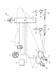
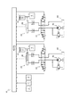
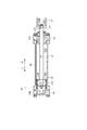
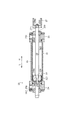
まず、図1から図8を用いてアウトドライブ装置10を備えた船舶100の全体概要及び構成について説明する。なお、図1及び図2の船舶100は、アウトドライブ装置10を二台備えた、いわゆる二軸推進方式の船舶を示している。但し、一軸推進方式等であっても成立し、これに限定するものではない。   First, an overall outline and configuration of a ship 100 including the outdrive device 10 will be described with reference to FIGS. 1 to 8. 1 and 2 is a so-called biaxial propulsion type ship including two outdrive devices 10. However, even a uniaxial propulsion method or the like is established, and the present invention is not limited to this.

図1及び図2に示すように、船舶100は、アクセルレバー2の操作に応じてエンジン5の運転状態が調節され、ひいてはスクリュープロペラ15の回転速度が変更されて推進する。船舶100は、船体1にアウトドライブ装置10と、油圧アクチュエータ20と、比例電磁弁30と、制御装置40とが具備される。船舶100は、船体1にアウトドライブ装置10を制御するための操舵ハンドル3やジョイスティックレバー4を具備する。さらに、船体1には、操舵ハンドル3又はジョイスティックレバー4の近傍にこれらの操作状況等の表示を行うモニタ6が設置される。船舶100は、操舵ハンドル3やジョイスティックレバー4の操作に応じてアウトドライブ装置10を回動可能に構成される。   As shown in FIGS. 1 and 2, the marine vessel 100 is propelled by adjusting the operating state of the engine 5 in accordance with the operation of the accelerator lever 2 and consequently changing the rotational speed of the screw propeller 15. A ship 100 includes an outdrive device 10, a hydraulic actuator 20, a proportional electromagnetic valve 30, and a control device 40 in a hull 1. The ship 100 includes a steering handle 3 and a joystick lever 4 for controlling the outdrive device 10 on the hull 1. Further, the hull 1 is provided with a monitor 6 for displaying the operation status and the like in the vicinity of the steering handle 3 or the joystick lever 4. The ship 100 is configured to be able to turn the outdrive device 10 in accordance with the operation of the steering handle 3 and the joystick lever 4.

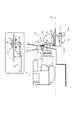
図3に示すように、アウトドライブ装置10は、スクリュープロペラ15を回転させることによって船体1を推進させる。また、アウトドライブ装置10は、船体1の進行方向に対して回動することによって該船体1を旋回させる。図3に示すように、アウトドライブ装置10は、主に入力軸11と、切換クラッチ12と、駆動軸13と、出力軸14と、スクリュープロペラ15と、で構成される。   As shown in FIG. 3, the outdrive device 10 propels the hull 1 by rotating a screw propeller 15. In addition, the outdrive device 10 turns the hull 1 by turning with respect to the traveling direction of the hull 1. As shown in FIG. 3, the outdrive device 10 mainly includes an input shaft 11, a switching clutch 12, a drive shaft 13, an output shaft 14, and a screw propeller 15.

入力軸11は、エンジン5の回転動力を切換クラッチ12に伝達する。入力軸11の一端部は、エンジン5の出力軸に取り付けられたユニバーサルジョイントと連結され、その他端部は、アッパーハウジング10Uの内部に配置された切換クラッチ12と連結される。   The input shaft 11 transmits the rotational power of the engine 5 to the switching clutch 12. One end of the input shaft 11 is connected to a universal joint attached to the output shaft of the engine 5, and the other end is connected to a switching clutch 12 disposed inside the upper housing 10U.

切換クラッチ12は、入力軸11等を介して伝達されたエンジン5の回転動力を正回転方向又は逆回転方向に切換可能とする。切換クラッチ12は、ディスクプレートを備えるインナードラムと連結された正回転用ベベルギア、ならびに、逆回転用ベベルギアを有し、入力軸11に連結されたアウタードラムのプレッシャープレートをいずれのディスクプレートに押し付けるかによって回転方向の切り換えを行なう。   The switching clutch 12 can switch the rotational power of the engine 5 transmitted via the input shaft 11 or the like between the forward rotation direction and the reverse rotation direction. The switching clutch 12 has a forward rotating bevel gear connected to an inner drum having a disk plate and a reverse rotating bevel gear, and which disk plate is pressed against the pressure plate of the outer drum connected to the input shaft 11. To change the direction of rotation.

駆動軸13は、切換クラッチ12等を介して伝達されたエンジン5の回転動力を出力軸14に伝達する。駆動軸13の一端部に設けられたベベルギアは、切換クラッチ12に設けられた正回転用ベベルギア、ならびに、逆回転用ベベルギアと歯合され、その他端部に設けられたベベルギアは、ロアハウジング10Rの内部に配置された出力軸14のベベルギアと歯合される。   The drive shaft 13 transmits the rotational power of the engine 5 transmitted through the switching clutch 12 and the like to the output shaft 14. The bevel gear provided at one end of the drive shaft 13 meshes with the forward rotation bevel gear and the reverse rotation bevel gear provided in the switching clutch 12, and the bevel gear provided at the other end of the lower housing 10R. It meshes with the bevel gear of the output shaft 14 arranged inside.

出力軸14は、駆動軸13等を介して伝達されたエンジン5の回転動力をスクリュープロペラ15に伝達する。出力軸14の一端部に設けられたベベルギアは、上述したように駆動軸13のベベルギアと歯合され、その他端部には、スクリュープロペラ15が取り付けられている。   The output shaft 14 transmits the rotational power of the engine 5 transmitted through the drive shaft 13 or the like to the screw propeller 15. The bevel gear provided at one end of the output shaft 14 meshes with the bevel gear of the drive shaft 13 as described above, and a screw propeller 15 is attached to the other end.

スクリュープロペラ15は、回転することによって推進力を発生させる。スクリュープロペラ15は、出力軸14等を介して伝達されたエンジン5の回転動力によって駆動され、回転軸周りに配置された複数枚のブレード15aが周囲の水をかくことによって推進力を発生させる。   The screw propeller 15 generates a propulsive force by rotating. The screw propeller 15 is driven by the rotational power of the engine 5 transmitted through the output shaft 14 and the like, and a plurality of blades 15a arranged around the rotational shaft generate propulsive force by removing surrounding water.

なお、アウトドライブ装置10は、船体1の船尾板(トランサムボード)に取り付けられたジンバルハウジング7に支持されている。具体的には、アウトドライブ装置10は、該アウトドライブ装置10のジンバルリング16が喫水線wlから略垂直方向となるようにジンバルハウジング7に支持されている。なお、ジンバルリング16とは、アウトドライブ装置10に取り付けられた略円筒形状の回動軸であり、アウトドライブ装置10は、該ジンバルリング16を中心として回動する。   The outdrive device 10 is supported by a gimbal housing 7 attached to a stern board (transom board) of the hull 1. Specifically, the outdrive device 10 is supported by the gimbal housing 7 so that the gimbal ring 16 of the outdrive device 10 is substantially perpendicular to the water line wl. The gimbal ring 16 is a substantially cylindrical rotation shaft attached to the outdrive device 10, and the outdrive device 10 rotates about the gimbal ring 16.

ジンバルリング16の上側端部には、船体1の内部に延設された操舵アーム19が取り付けられている。そして、操舵アーム19は、ジンバルリング16を中心にアウトドライブ装置10を回動させる。なお、操舵アーム19は、操舵ハンドル3やジョイスティックレバー4の操作に応じて連動する油圧アクチュエータ20によって駆動される。   A steering arm 19 extending inside the hull 1 is attached to the upper end portion of the gimbal ring 16. Then, the steering arm 19 rotates the outdrive device 10 around the gimbal ring 16. The steering arm 19 is driven by a hydraulic actuator 20 that is interlocked according to the operation of the steering handle 3 and the joystick lever 4.

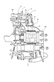
ここで、図4から図6を用いてアウトドライブ装置10の取り付け構造について詳細に説明する。   Here, the mounting structure of the outdrive device 10 will be described in detail with reference to FIGS.

船尾板(トランサムボード)の前面側には、ブラケット8が取り付けられている。また、船尾板(トランサムボード)の後面側には、ジンバルハウジング7が取り付けられている。そして、ジンバルハウジング7には、回動軸17・17が略垂直方向に設けられ、ジンバルリング16は、回動軸17・17によって回動自在に支持されている。また、ジンバルリング16の中途部には、回動軸18・18が水平方向に設けられ、アッパーハウジング10Uの前上部は、回動軸18・18によって回動自在に支持されている。   A bracket 8 is attached to the front side of the stern board (transom board). A gimbal housing 7 is attached to the rear side of the stern board (transom board). The gimbal housing 7 is provided with pivot shafts 17 and 17 in a substantially vertical direction, and the gimbal ring 16 is rotatably supported by the pivot shafts 17 and 17. In addition, in the middle part of the gimbal ring 16, rotational shafts 18 and 18 are provided in the horizontal direction, and the front upper portion of the upper housing 10U is rotatably supported by the rotational shafts 18 and 18.

回動軸17の上側端部には、操舵アーム19が取り付けられている。操舵アーム19は、船体1及びブラケット8に設けられた貫通孔1H・8Hを通って船体1の内部に延設されている。そして、操舵アーム19の端部には、油圧アクチュエータ20が連結されている(図3参照)。従って、アウトドライブ装置10は、油圧アクチュエータ20が作動することによって、ジンバルリング16を中心に左右に回動するのである。   A steering arm 19 is attached to the upper end of the rotation shaft 17. The steering arm 19 extends inside the hull 1 through through holes 1H and 8H provided in the hull 1 and the bracket 8. A hydraulic actuator 20 is connected to the end of the steering arm 19 (see FIG. 3). Therefore, the outdrive device 10 rotates to the left and right around the gimbal ring 16 when the hydraulic actuator 20 is operated.

なお、ジンバルリング16の下部とアッパーハウジング10Uとの間には、昇降用油圧アクチュエータ9が介装されている(図3参照)。従って、アウトドライブ装置10は、昇降用油圧アクチュエータ9が作動することによって、回動軸18・18を中心に上下に回動するのである。   An elevating hydraulic actuator 9 is interposed between the lower part of the gimbal ring 16 and the upper housing 10U (see FIG. 3). Therefore, the outdrive device 10 rotates up and down around the rotation shafts 18 and 18 by the operation of the lifting hydraulic actuator 9.

油圧アクチュエータ20は、アウトドライブ装置10の操舵アーム19を駆動して該アウトドライブ装置10を回動させる。図5に示すように、油圧アクチュエータ20は、主にシリンダスリーブ21と、ピストン22と、ロッド23と、第一シリンダキャップ24と、第二シリンダキャップ25と、位置センサ26と、で構成される。なお、本実施形態に係る油圧アクチュエータ20は、いわゆる片ロッド型の油圧アクチュエータであるが、図6に示すように両ロッド型であっても良い。   The hydraulic actuator 20 drives the steering arm 19 of the outdrive device 10 to rotate the outdrive device 10. As shown in FIG. 5, the hydraulic actuator 20 mainly includes a cylinder sleeve 21, a piston 22, a rod 23, a first cylinder cap 24, a second cylinder cap 25, and a position sensor 26. . The hydraulic actuator 20 according to the present embodiment is a so-called single rod type hydraulic actuator, but may be a double rod type as shown in FIG.

シリンダスリーブ21は、ピストン22を摺動可能に内設する。シリンダスリーブ21の両端部には、周方向に突設された鍔部が設けられており、該鍔部には、第一シリンダキャップ24又は第二シリンダキャップ25が固設される。   The cylinder sleeve 21 has a piston 22 slidably provided therein. Both ends of the cylinder sleeve 21 are provided with flanges protruding in the circumferential direction, and the first cylinder cap 24 or the second cylinder cap 25 is fixed to the flanges.

ピストン22は、油圧を受けることによってシリンダスリーブ21の内部を摺動する。ピストン22には、該ピストン22の中心軸と同軸に貫通孔22hが設けられており、該貫通孔22hには、ロッド23が挿通されている。また、ピストン22の外周面には、その周方向にリング溝が設けられており、該リング溝には、シールリングが環装されている。更に、各シールリングの間であってピストン22の外周面には、永久磁石222が取り付けられている。   The piston 22 slides inside the cylinder sleeve 21 by receiving hydraulic pressure. The piston 22 is provided with a through hole 22h coaxially with the central axis of the piston 22, and a rod 23 is inserted into the through hole 22h. Further, a ring groove is provided on the outer peripheral surface of the piston 22 in the circumferential direction, and a seal ring is provided around the ring groove. Further, a permanent magnet 222 is attached to the outer peripheral surface of the piston 22 between the seal rings.

ロッド23は、ピストン22の摺動を操舵アーム19に伝達する。ロッド23の一端部には、該ロッド23の外径を縮径した縮径部23taが設けられている。そして、ロッド23は、ピストン22の貫通孔22hに縮径部23taを挿通した状態でナット231が螺合されて該ピストン22と固設される。また、ロッド23の他端部には、該ロッド23の外径を縮径した縮径部23tbが設けられている。そして、ロッド23は、クレビス27の貫通孔27hに縮径部23tbを挿通した状態でナット232が螺合されて該クレビス27と固設される。なお、クレビス27とは、ロッド23と操舵アーム19とを連結する連結部材である。   The rod 23 transmits the sliding movement of the piston 22 to the steering arm 19. One end portion of the rod 23 is provided with a reduced diameter portion 23ta in which the outer diameter of the rod 23 is reduced. The rod 23 is fixed to the piston 22 by being screwed with a nut 231 in a state where the reduced diameter portion 23 ta is inserted into the through hole 22 h of the piston 22. Further, the other end portion of the rod 23 is provided with a reduced diameter portion 23tb obtained by reducing the outer diameter of the rod 23. The rod 23 is fixed to the clevis 27 by being screwed with a nut 232 in a state where the reduced diameter portion 23 tb is inserted into the through hole 27 h of the clevis 27. The clevis 27 is a connecting member that connects the rod 23 and the steering arm 19.

第一シリンダキャップ24は、シリンダスリーブ21の一端部を密封する。第一シリンダキャップ24には、シリンダスリーブ21とピストン22で構成された第一油室Oc1に連通する第一油路24pが設けられている。また、シリンダスリーブ21に嵌入される周壁面には、その周方向にリング溝が設けられてシールリングが環装されている。これにより、第一油室Oc1は、所定の油圧に耐え得る耐圧室を構成している。   The first cylinder cap 24 seals one end of the cylinder sleeve 21. The first cylinder cap 24 is provided with a first oil passage 24p that communicates with a first oil chamber Oc1 constituted by a cylinder sleeve 21 and a piston 22. Further, a ring groove is provided in the circumferential direction on the peripheral wall surface inserted into the cylinder sleeve 21, and a seal ring is provided around the peripheral wall surface. Thereby, the first oil chamber Oc1 constitutes a pressure chamber that can withstand a predetermined oil pressure.

第二シリンダキャップ25は、シリンダスリーブ21の他端部を密封するとともに、ロッド23を摺動可能に支持する。第二シリンダキャップ25には、シリンダスリーブ21とピストン22で構成された第二油室Oc2に連通する第二油路25pが設けられている。また、シリンダスリーブ21に嵌入される周壁面には、その周方向にリング溝が設けられてシールリングが環装されている。更に、第二シリンダキャップ25には、シリンダスリーブ21の中心軸と同軸に貫通孔25hが設けられており、該貫通孔25hには、ロッド23が摺動可能に挿通される。なお、貫通孔25hの内周面には、その周方向にリング溝が設けられており、該リング溝には、シールリングが嵌挿されている。これにより、第二油室Oc2は、所定の油圧に耐え得る耐圧室を構成している。   The second cylinder cap 25 seals the other end of the cylinder sleeve 21 and supports the rod 23 in a slidable manner. The second cylinder cap 25 is provided with a second oil passage 25p that communicates with a second oil chamber Oc2 constituted by the cylinder sleeve 21 and the piston 22. Further, a ring groove is provided in the circumferential direction on the peripheral wall surface inserted into the cylinder sleeve 21, and a seal ring is provided around the peripheral wall surface. Further, the second cylinder cap 25 is provided with a through hole 25h coaxially with the central axis of the cylinder sleeve 21, and the rod 23 is slidably inserted into the through hole 25h. A ring groove is provided in the circumferential direction on the inner peripheral surface of the through hole 25h, and a seal ring is fitted into the ring groove. Thus, the second oil chamber Oc2 constitutes a pressure-resistant chamber that can withstand a predetermined oil pressure.

位置センサ26は、ピストン22に取り付けられた永久磁石222の磁力を検出する。位置センサ26は、少なくともピストン22が摺動できる範囲内において該ピストン22の摺動方向に対して平行となるようにシリンダスリーブ21の外周面に取り付けられている。これにより、制御装置40は、ピストン22の位置を把握することができ、ひいてはアウトドライブ装置10の舵角度を把握することができるのである。また、制御装置40は、単位時間毎にピストン22の位置を把握することで該ピストン22の摺動方向を認識できる。   The position sensor 26 detects the magnetic force of the permanent magnet 222 attached to the piston 22. The position sensor 26 is attached to the outer peripheral surface of the cylinder sleeve 21 so as to be parallel to the sliding direction of the piston 22 at least within a range in which the piston 22 can slide. Thereby, the control apparatus 40 can grasp | ascertain the position of the piston 22, and can grasp | ascertain the steering angle of the outdrive apparatus 10 by extension. Further, the control device 40 can recognize the sliding direction of the piston 22 by grasping the position of the piston 22 every unit time.

なお、位置センサ26は、主に磁束密度の変化に応じて出力電圧を変換する、いわゆるホール素子で構成されている。ホール素子は、磁界と電流の相互作用によって電子にローレンツ力が作用することを利用し、ローレンツ力に起因する電位差(ホール電圧)から磁界の強さを検出する。なお、本実施形態においては、位置センサ26の主な構成要素としてホール素子を用いているが、磁界の強さに応じて電気抵抗値が変化する磁気抵抗素子を用いても良く、これに限定するものではない。   The position sensor 26 is mainly composed of a so-called Hall element that converts an output voltage in accordance with a change in magnetic flux density. The Hall element detects the strength of the magnetic field from the potential difference (Hall voltage) caused by the Lorentz force by utilizing the Lorentz force acting on the electrons due to the interaction between the magnetic field and the current. In the present embodiment, the Hall element is used as the main component of the position sensor 26. However, a magnetoresistive element whose electric resistance value changes according to the strength of the magnetic field may be used, and the present invention is not limited thereto. Not what you want.

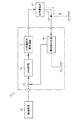
比例電磁弁30は、油圧アクチュエータ20の作動油の流動方向を変更する。図7及び図8に示すように、比例電磁弁30は、主にバルブボディ31と、スプールシャフト32と、第一ソレノイド33と、第二ソレノイド34と、で構成される。バルブボディ31は、スプールシャフト32を摺動可能に内設する。スプールシャフト32は、バルブボディ31の内部を摺動することによって作動油の油路を切り換える。第一ソレノイド33は、スプールシャフト32を一方に摺動させる。第二ソレノイド34は、スプールシャフト32を他方に摺動させる。比例電磁弁30は、ドライバ35から第一ソレノイド33又は第二ソレノイド34に電流Iが供給される。なお、本実施形態における比例電磁弁30は、いわゆる直動形比例電磁弁であるが、パイロット形比例電磁弁であっても良く、作動形式を限定するものではない。   The proportional solenoid valve 30 changes the flow direction of the hydraulic oil of the hydraulic actuator 20. As shown in FIGS. 7 and 8, the proportional electromagnetic valve 30 mainly includes a valve body 31, a spool shaft 32, a first solenoid 33, and a second solenoid 34. The valve body 31 has a spool shaft 32 slidably provided therein. The spool shaft 32 switches the oil passage of the hydraulic oil by sliding inside the valve body 31. The first solenoid 33 slides the spool shaft 32 in one direction. The second solenoid 34 slides the spool shaft 32 to the other side. The proportional solenoid valve 30 is supplied with a current I from the driver 35 to the first solenoid 33 or the second solenoid 34. In addition, although the proportional solenoid valve 30 in this embodiment is what is called a direct-acting proportional solenoid valve, it may be a pilot-type proportional solenoid valve and does not limit the operation type.

ドライバ35は、制御装置40からの信号に基づいて比例電磁弁30に電流Iを流す。図8に示すように、ドライバ35は、PWM回路(パルス幅変調回路)36と、比例電磁弁駆動回路37と、電流検出回路38とから構成される。PWM回路36は、制御装置40からの制御信号を受信可能に構成される。また、PWM回路36は、受信した制御信号に基づいて比例電磁弁駆動回路37に制御パルスを送信可能に構成される。比例電磁弁駆動回路37は、PWM回路36から受信した制御パルスに基づいて比例電磁弁30に電流Iを供給可能に構成される。電流検出回路38は、比例電磁弁30に供給された電流Iが通電可能に構成される。電流検出回路38は、電流Iが流れる図示しないシャント抵抗での電圧低下から電流値を検出する。また、電流検出回路38は、減算器39を介して検出した電流値をPWM回路36に入力可能に構成される。つまり、ドライバ35は、制御信号と電流検出値との偏差に基づいて電流フィードバック制御を行う。   The driver 35 causes a current I to flow through the proportional solenoid valve 30 based on a signal from the control device 40. As shown in FIG. 8, the driver 35 includes a PWM circuit (pulse width modulation circuit) 36, a proportional solenoid valve drive circuit 37, and a current detection circuit 38. The PWM circuit 36 is configured to be able to receive a control signal from the control device 40. The PWM circuit 36 is configured to be able to transmit a control pulse to the proportional solenoid valve drive circuit 37 based on the received control signal. The proportional solenoid valve drive circuit 37 is configured to be able to supply the current I to the proportional solenoid valve 30 based on the control pulse received from the PWM circuit 36. The current detection circuit 38 is configured such that the current I supplied to the proportional solenoid valve 30 can be energized. The current detection circuit 38 detects a current value from a voltage drop at a shunt resistor (not shown) through which the current I flows. Further, the current detection circuit 38 is configured to be able to input the current value detected via the subtractor 39 to the PWM circuit 36. That is, the driver 35 performs current feedback control based on the deviation between the control signal and the current detection value.

図2に示すように、制御装置40は、アクセルレバー2、操舵ハンドル3及びジョイスティックレバー4等からの検出信号に基づいて制御信号を作成する。そして、制御装置40は、制御信号を比例電磁弁30のドライバ35等に送信する。また、制御装置40は、全地球測位システム(GPS:Global Positioning System)からの情報に基づいて制御信号を作成するとともに、作成した制御信号を比例電磁弁30等に送信することも可能としている。つまり、制御装置40は、オペレータが手動で行なう操船のほかに、自らの位置と設定された目的地とから航路を算出して自動で操船を行なう、いわゆる自動航法を可能としている。   As shown in FIG. 2, the control device 40 creates a control signal based on detection signals from the accelerator lever 2, the steering handle 3, the joystick lever 4, and the like. And the control apparatus 40 transmits a control signal to the driver 35 etc. of the proportional solenoid valve 30 grade | etc.,. In addition, the control device 40 creates a control signal based on information from a global positioning system (GPS), and can also send the created control signal to the proportional solenoid valve 30 or the like. That is, the control device 40 enables so-called automatic navigation in which the navigation is automatically performed by calculating the route from its own position and the set destination, in addition to the navigation manually performed by the operator.

制御装置40は、船体1にアウトドライブ装置10を組み付けた際に行うアウトドライブ装置10の自動校正機能を有する。具体的には、制御装置40は、油圧アクチュエータ20の油圧管の接続確認及び可動範囲の設定、位置センサ26の電線の配線の適否判定、比例電磁弁30の油圧管の配管の適否判定、比例電磁弁30のドライバ35の短絡故障の有無判断等を行う自動校正を実施することができる。制御装置40は、自動校正を実施するための各種プログラムやデータ等が記憶されている。   The control device 40 has an automatic calibration function of the outdrive device 10 that is performed when the outdrive device 10 is assembled to the hull 1. Specifically, the control device 40 confirms the connection of the hydraulic pipe of the hydraulic actuator 20 and sets the movable range, determines the suitability of the wiring of the position sensor 26, determines the suitability of the piping of the hydraulic pipe of the proportional solenoid valve 30, proportional Automatic calibration for determining the presence or absence of a short circuit failure of the driver 35 of the solenoid valve 30 can be performed. The control device 40 stores various programs and data for performing automatic calibration.

このように構成されるアウトドライブ装置10を備えた船舶100について、船体1を左旋回させる場合、制御装置40は、油圧アクチュエータ20のピストン22を図5、図6に示す矢印Lの方向に摺動させる必要がある。従って、制御装置40は、比例電磁弁30に制御信号を送信することによって第二ソレノイド34を作動させる。これにより、第二ソレノイド34は、スプールシャフト32を所定の位置まで摺動させる(図8B参照)。その結果、油圧アクチュエータ20のピストン22は、図5、図6に示す矢印Lの方向に摺動することとなる。   When the ship 100 having the outdrive device 10 configured as described above is turned left, the control device 40 slides the piston 22 of the hydraulic actuator 20 in the direction of the arrow L shown in FIGS. It is necessary to move. Therefore, the control device 40 operates the second solenoid 34 by transmitting a control signal to the proportional solenoid valve 30. Thereby, the second solenoid 34 slides the spool shaft 32 to a predetermined position (see FIG. 8B). As a result, the piston 22 of the hydraulic actuator 20 slides in the direction of the arrow L shown in FIGS.

船体1を右旋回させる場合、制御装置40は、油圧アクチュエータ20のピストン22を図5、図6に示す矢印Rの方向に摺動させる必要がある。従って、制御装置40は、比例電磁弁30に制御信号を送信することによって第一ソレノイド33を作動させる。これにより、第一ソレノイド33は、スプールシャフト32を所定の位置まで摺動させる(図8C参照)。その結果、油圧アクチュエータ20のピストン22は、図5、図6に示す矢印Rの方向に摺動することとなる。   When the hull 1 is turned to the right, the control device 40 needs to slide the piston 22 of the hydraulic actuator 20 in the direction of the arrow R shown in FIGS. Therefore, the control device 40 operates the first solenoid 33 by transmitting a control signal to the proportional solenoid valve 30. Thereby, the first solenoid 33 slides the spool shaft 32 to a predetermined position (see FIG. 8C). As a result, the piston 22 of the hydraulic actuator 20 slides in the direction of the arrow R shown in FIGS.

以下では、船舶100のアウトドライブ装置10における自動校正機能の動作態様について説明する。   Below, the operation | movement aspect of the automatic calibration function in the outdrive apparatus 10 of the ship 100 is demonstrated.

制御装置40は、モニタ6に表示される「校正実施」が選択されると、アウトドライブ装置10を構成する油圧アクチュエータ20のピストン22を動作させて、油圧アクチュエータ20、位置センサ26、比例電磁弁30、及びドライバ35の電線及び油圧管の接続について確認する。次に、制御装置40は、ピストン22を移動させて一側端及び他側端における位置センサ26の値を設定するとともに、油圧アクチュエータ20、位置センサ26、比例電磁弁30、及びドライバ35の電線及び油圧管の誤配線及び誤配管の判定を行う。次に、制御装置40は、比例電磁弁30の駆動回路における短絡故障の判定を行う。最後に、制御装置40は、油圧アクチュエータ20を作動させるために必要な最小電流値Iminを設定する。   When “calibration execution” displayed on the monitor 6 is selected, the control device 40 operates the piston 22 of the hydraulic actuator 20 constituting the outdrive device 10, and the hydraulic actuator 20, the position sensor 26, and the proportional solenoid valve. 30 and the connection of the electric wire and hydraulic pipe of the driver 35 are confirmed. Next, the control device 40 moves the piston 22 to set the value of the position sensor 26 at the one side end and the other side end, and the electric wires of the hydraulic actuator 20, the position sensor 26, the proportional electromagnetic valve 30, and the driver 35. Also, check for incorrect wiring and incorrect piping of hydraulic pipes. Next, the control device 40 determines a short circuit failure in the drive circuit of the proportional solenoid valve 30. Finally, the control device 40 sets a minimum current value Imin necessary for operating the hydraulic actuator 20.

次に、図9から図13を用いて上述の制御装置40の自動校正の制御態様について具体的に説明する。   Next, the control mode of the automatic calibration of the control device 40 described above will be specifically described with reference to FIGS.

図9に示すように、ステップS100において、制御装置40は、モニタ6に表示されている「校正実施」が選択されたことによる校正信号を受信したか否かを判定する。
その結果、校正信号を受信したと判定した場合、制御装置40はステップをステップS200に移行させる。
一方、校正信号を受信していないと判定した場合、制御装置40は自動校正の制御を終了する。
As shown in FIG. 9, in step S <b> 100, the control device 40 determines whether or not a calibration signal due to selection of “Calibration performed” displayed on the monitor 6 has been received.
As a result, when it is determined that the calibration signal has been received, the control device 40 shifts the step to step S200.
On the other hand, if it is determined that the calibration signal has not been received, the control device 40 ends the automatic calibration control.

ステップS200において、制御装置40は、接続確認制御Aを開始し、ステップをステップS201に移行させる(図10参照)。接続確認制御Aが終了すると、制御装置40はステップをステップS300に移行させる(図9参照)。   In step S200, the control device 40 starts connection confirmation control A, and shifts the step to step S201 (see FIG. 10). When the connection confirmation control A ends, the control device 40 shifts the step to step S300 (see FIG. 9).

ステップS300において、制御装置40は、接続確認制御Aにおける判定結果に基づいて電線又は油圧管に接続不良が無いか否かを判定する。
その結果、電線及び油圧管に接続不良が無いと判定した場合、制御装置40はステップをステップS400に移行させる。
一方、電線又は油圧管に接続不良が有ると判定した場合、制御装置40は自動校正の制御を終了する。この場合、モニタ6に電線又は油圧管に接続不良が有る旨が表示される。
In step S300, the control device 40 determines whether there is no connection failure in the electric wire or the hydraulic pipe based on the determination result in the connection confirmation control A.
As a result, when it is determined that there is no connection failure in the electric wire and the hydraulic pipe, the control device 40 shifts the step to step S400.
On the other hand, if it is determined that there is a connection failure in the electric wire or hydraulic pipe, the control device 40 ends the automatic calibration control. In this case, the monitor 6 indicates that there is a connection failure in the electric wire or hydraulic pipe.

ステップS400において、制御装置40は、アクチュエータ校正制御Bを開始し、ステップをステップS401に移行させる(図11参照)。アクチュエータ校正制御Bが終了すると、制御装置40はステップをステップS500に移行させる(図9参照)。   In step S400, the control device 40 starts actuator calibration control B, and shifts the step to step S401 (see FIG. 11). When the actuator calibration control B ends, the control device 40 shifts the step to step S500 (see FIG. 9).

ステップS500において、制御装置40は、アクチュエータ校正制御Bにおける判定結果に基づいて電線の誤配線、油圧管の誤配管又は油圧アクチュエータ20の動作不良が無いか否かを判定する。
その結果、電線の誤配線、油圧管の誤配管又は油圧アクチュエータ20の動作不良が無いと判定した場合、制御装置40はステップをステップS600に移行させる。
一方、電線の誤配線、油圧管の誤配管及び油圧アクチュエータ20の動作不良が有ると判定した場合、制御装置40は自動校正の制御を終了する。この場合、モニタ6に電線の誤配線、油圧管の誤配管又は油圧アクチュエータ20の動作不良が有る旨が表示される。
In step S <b> 500, the control device 40 determines based on the determination result in the actuator calibration control B whether or not there is an erroneous wiring of the electric wire, incorrect piping of the hydraulic pipe, or malfunction of the hydraulic actuator 20.
As a result, when it is determined that there is no erroneous wiring of the electric wire, incorrect piping of the hydraulic pipe, or malfunction of the hydraulic actuator 20, the control device 40 shifts the step to step S600.
On the other hand, when it is determined that there is an incorrect wiring of the electric wire, an incorrect piping of the hydraulic pipe, and a malfunction of the hydraulic actuator 20, the control device 40 ends the control of the automatic calibration. In this case, the monitor 6 indicates that there is an incorrect wiring of the electric wire, an incorrect piping of the hydraulic pipe, or a malfunction of the hydraulic actuator 20.

ステップS600において、制御装置40は、短絡故障確認制御Cを開始し、ステップをステップS601に移行させる(図12参照)。短絡故障確認制御Cが終了すると、制御装置40はステップをステップS700に移行させる(図9参照)。   In step S600, the control device 40 starts the short circuit failure confirmation control C, and shifts the step to step S601 (see FIG. 12). When the short circuit failure confirmation control C is completed, the control device 40 shifts the step to step S700 (see FIG. 9).

ステップS700において、制御装置40は、短絡故障確認制御Cにおける判定結果に基づいて比例電磁弁30の駆動回路における短絡故障が無いか否かを判定する。
その結果、比例電磁弁30の駆動回路における短絡故障が無いと判定した場合、制御装置40はステップをステップS800に移行させる。
一方、比例電磁弁30の駆動回路における短絡故障が有ると判定した場合、制御装置40は自動校正の制御を終了する。この場合、モニタ6にドライバ35の短絡故障が有る旨が表示される。
In step S700, the control device 40 determines whether or not there is a short circuit failure in the drive circuit of the proportional solenoid valve 30 based on the determination result in the short circuit failure confirmation control C.
As a result, when it is determined that there is no short circuit failure in the drive circuit of the proportional solenoid valve 30, the control device 40 shifts the step to step S800.
On the other hand, when it is determined that there is a short circuit failure in the drive circuit of the proportional solenoid valve 30, the control device 40 ends the automatic calibration control. In this case, the monitor 6 indicates that there is a short circuit fault in the driver 35.

ステップS800において、制御装置40は、ドライバ校正制御Dを開始し、ステップをステップS801に移行させる(図13参照)。ドライバ校正制御Dが終了すると、制御装置40は自動校正の制御を終了する(図9参照)。つまり、制御装置40は、接続確認制御A、アクチュエータ校正制御B、短絡故障確認制御C及びドライバ校正制御Dにおいて、動作不良、誤配管、故障等が有ると判定されると自動校正の制御を終了する。   In step S800, the control device 40 starts driver calibration control D, and shifts the step to step S801 (see FIG. 13). When the driver calibration control D ends, the control device 40 ends the automatic calibration control (see FIG. 9). That is, the control device 40 ends the automatic calibration control when it is determined that there is an operation failure, an incorrect piping, a failure, or the like in the connection confirmation control A, actuator calibration control B, short circuit failure confirmation control C, and driver calibration control D. To do.

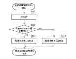
図10に示すように、接続確認制御AのステップS201において、制御装置40は、油圧アクチュエータ20を所定方向に作動させ、ステップをステップS202に移行させる。具体的には、制御装置40は、比例電磁弁30によって作動油の方向を切り換えて油圧アクチュエータ20のピストン22を所定量Svだけ一側、他側、一側の順に移動させ、ステップをステップS202に移行させる。   As shown in FIG. 10, in step S201 of the connection confirmation control A, the control device 40 operates the hydraulic actuator 20 in a predetermined direction, and shifts the step to step S202. Specifically, the control device 40 switches the direction of the hydraulic oil by the proportional solenoid valve 30 and moves the piston 22 of the hydraulic actuator 20 by a predetermined amount Sv in order of one side, the other side, and one side, and the step is step S202. To migrate.

ステップS202において、制御装置40は、油圧アクチュエータ20の作動に伴って位置センサ26の検出値Pが所定値Pv以上変動したか否かを判定する。
その結果、位置センサ26の検出値Pが所定値Pv以上変動したと判定した場合、制御装置40はステップをステップS203に移行させる。
一方、位置センサ26の検出値Pが所定値Pv以上変動していないと判定した場合、制御装置40はステップをステップS213に移行させる。
In step S202, the control device 40 determines whether or not the detection value P of the position sensor 26 has fluctuated by a predetermined value Pv or more with the operation of the hydraulic actuator 20.
As a result, when it is determined that the detection value P of the position sensor 26 has fluctuated by the predetermined value Pv or more, the control device 40 shifts the step to step S203.
On the other hand, when it is determined that the detection value P of the position sensor 26 has not fluctuated more than the predetermined value Pv, the control device 40 shifts the step to step S213.

ステップS203において、制御装置40は、電線及び油圧管の接続不良が無いと判定して、接続確認制御Aを終了する。具体的には、制御装置40は、位置センサ26、比例電磁弁30、ドライバ35に関する電線の接続不良及び油圧アクチュエータ20に関する油圧管の接続不良が無いと判定して、接続確認制御Aを終了する。   In step S203, the control device 40 determines that there is no connection failure between the electric wire and the hydraulic pipe, and ends the connection confirmation control A. Specifically, the control device 40 determines that there is no connection failure of the electric wires related to the position sensor 26, the proportional solenoid valve 30, and the driver 35 and a connection failure of the hydraulic pipe related to the hydraulic actuator 20, and ends the connection confirmation control A. .

ステップS213において、制御装置40は、電線又は油圧管の接続不良が有ると判定して、接続確認制御Aを終了する。具体的には、制御装置40は、位置センサ26、比例電磁弁30、ドライバ35の電線の接続不良又は油圧アクチュエータ20に関する油圧管の接続不良が有ると判定して、接続確認制御Aを終了する。   In step S213, the control device 40 determines that there is a connection failure of the electric wire or the hydraulic pipe, and ends the connection confirmation control A. Specifically, the control device 40 determines that there is a connection failure of the position sensor 26, the proportional electromagnetic valve 30, and the driver 35 or a connection failure of the hydraulic pipe related to the hydraulic actuator 20, and ends the connection confirmation control A. .

図11に示すように、アクチュエータ校正制御BのステップS401において、制御装置40は、油圧アクチュエータ20のピストン22を一側及び他側に向けて移動させて、ステップをステップS402に移行させる。   As shown in FIG. 11, in step S401 of the actuator calibration control B, the control device 40 moves the piston 22 of the hydraulic actuator 20 toward one side and the other side, and shifts the step to step S402.

ステップS402において、制御装置40は、油圧アクチュエータ20のピストン22を一側又は他側に向けて移動した際の位置センサ26の検出値Pが第1校正範囲R1内又は第2校正範囲R2内か否かを判定する。
その結果、検出値Pが第1校正範囲R1内又は第2校正範囲R2内であると判定した場合、制御装置40はステップをステップS403に移行させる。
一方、検出値Pが第1校正範囲R1内及び第2校正範囲R2内で無いと判定した場合、制御装置40はステップをステップS401に移行させる。
In step S402, the control device 40 determines whether the detected value P of the position sensor 26 when the piston 22 of the hydraulic actuator 20 is moved toward one side or the other side is within the first calibration range R1 or the second calibration range R2. Determine whether or not.
As a result, when it is determined that the detected value P is within the first calibration range R1 or the second calibration range R2, the control device 40 shifts the step to step S403.
On the other hand, when it is determined that the detected value P is not within the first calibration range R1 and the second calibration range R2, the control device 40 shifts the step to step S401.

ステップS403において、制御装置40は、油圧アクチュエータ20のピストン22を一側又は他側に向けて移動した際の位置センサ26の検出値Pが所定時間t1継続して検出されたか否かを判定する。
その結果、検出値Pが所定時間t1継続して検出されたと判定した場合、制御装置40はステップをステップS404に移行させる。
一方、検出値Pが所定時間t1継続して検出されていないと判定した場合、制御装置40はステップをステップS401に移行させる。
In step S403, the control device 40 determines whether or not the detection value P of the position sensor 26 when the piston 22 of the hydraulic actuator 20 is moved toward one side or the other is continuously detected for a predetermined time t1. .
As a result, when it is determined that the detection value P is detected continuously for the predetermined time t1, the control device 40 shifts the step to step S404.
On the other hand, when it is determined that the detection value P is not detected continuously for the predetermined time t1, the control device 40 shifts the step to step S401.

ステップS404において、制御装置40は、油圧アクチュエータ20のピストン22を一側及び他側に向けて移動させた際の位置センサ26の検出値P1を一側端の位置(以下、単に「一側端位置P1」と記す)、検出値P2を他側端の位置(以下、単に「他側端位置P2」と記す)として設定し、ステップをステップS405に移行させる。なお、本実施形態において、位置センサ26の検出値Pの値は、ピストン22が油圧アクチュエータ20の一側に移動するほど大きくなるように設定されている。   In step S <b> 404, the control device 40 sets the detection value P <b> 1 of the position sensor 26 when the piston 22 of the hydraulic actuator 20 is moved toward the one side and the other side to the position of one side end (hereinafter simply referred to as “one side end”). The detection value P2 is set as the position of the other side end (hereinafter simply referred to as “the other side end position P2”), and the process proceeds to step S405. In the present embodiment, the detection value P of the position sensor 26 is set so as to increase as the piston 22 moves to one side of the hydraulic actuator 20.

ステップS405において、制御装置40は、一側端位置P1が他側端位置P2よりも大きいか否かを判定する。
その結果、一側端位置P1が他側端位置P2よりも大きいと判定した場合、制御装置40はステップをステップS406に移行させる。
一方、一側端位置P1が他側端位置P2以下であると判定した場合、制御装置40はステップをステップS427に移行させる。
In step S405, the control device 40 determines whether or not the one side end position P1 is larger than the other side end position P2.
As a result, when it is determined that the one side end position P1 is larger than the other side end position P2, the control device 40 shifts the step to step S406.
On the other hand, when it is determined that the one side end position P1 is equal to or less than the other side end position P2, the control device 40 shifts the step to step S427.

ステップS406において、制御装置40は、一側端位置P1と他側端位置P2との差が所定値Lv以上か否かを判定する。
その結果、一側端位置P1と他側端位置P2との差が所定値Lv以上であると判定した場合、制御装置40はステップをステップS407に移行させる。
一方、一側端位置P1と他側端位置P2との差が所定値Lv未満であると判定した場合、制御装置40はステップをステップS417に移行させる。なお、本実施形態において、所定値Lvは、油圧アクチュエータ20の基準ストロークである。
In step S406, the control device 40 determines whether or not the difference between the one side end position P1 and the other side end position P2 is greater than or equal to a predetermined value Lv.
As a result, when it is determined that the difference between the one side end position P1 and the other side end position P2 is equal to or greater than the predetermined value Lv, the control device 40 shifts the step to step S407.
On the other hand, when it is determined that the difference between the one-side end position P1 and the other-side end position P2 is less than the predetermined value Lv, the control device 40 shifts the step to step S417. In the present embodiment, the predetermined value Lv is a reference stroke of the hydraulic actuator 20.

ステップS407において、制御装置40は、誤配線、誤配管及び動作不良が無いと判定して、アクチュエータ校正制御Bを終了する。具体的には、制御装置40は、位置センサ26、比例電磁弁30、ドライバ35に関する電線の誤配線及び油圧アクチュエータ20に関する油圧管の誤配管、油圧アクチュエータ20の動作不良が無いと判定して、アクチュエータ校正制御Bを終了する。   In step S407, the control device 40 determines that there is no erroneous wiring, erroneous piping, or malfunction, and ends the actuator calibration control B. Specifically, the control device 40 determines that there is no miswiring of the electric wires related to the position sensor 26, the proportional solenoid valve 30, and the driver 35, the incorrect piping of the hydraulic pipe related to the hydraulic actuator 20, and the malfunction of the hydraulic actuator 20. The actuator calibration control B is terminated.

ステップS417において、制御装置40は、動作不良と判定して、アクチュエータ校正制御Bを終了する。具体的には、制御装置40は、油圧アクチュエータ20の動作不良であると判定して、アクチュエータ校正制御Bを終了する。   In step S417, the control device 40 determines that the operation is defective and ends the actuator calibration control B. Specifically, the control device 40 determines that the hydraulic actuator 20 is malfunctioning and ends the actuator calibration control B.

ステップS427において、制御装置40は、誤配線又は誤配管が有ると判定して、アクチュエータ校正制御Bを終了する。具体的には、制御装置40は、位置センサ26、比例電磁弁30、ドライバ35に関する電線の誤配線又は油圧アクチュエータ20に関する油圧管の誤配管が有ると判定して、アクチュエータ校正制御Bを終了する。   In step S427, the control device 40 determines that there is an incorrect wiring or incorrect piping, and ends the actuator calibration control B. Specifically, the control device 40 determines that there is an incorrect wiring of the electric wire related to the position sensor 26, the proportional electromagnetic valve 30, and the driver 35 or an incorrect piping of the hydraulic pipe related to the hydraulic actuator 20, and ends the actuator calibration control B. .

図12に示すように、短絡故障確認制御CのステップS601において、制御装置40は、通常であれば比例電磁弁30を作動させることがない程度の電流I0をドライバ35から比例電磁弁30に流し、ステップをステップS602に移行させる。   As shown in FIG. 12, in step S601 of the short-circuit failure confirmation control C, the control device 40 sends a current I0 from the driver 35 to the proportional solenoid valve 30 so as not to normally operate the proportional solenoid valve 30. , The process proceeds to step S602.

ステップS602において、制御装置40は、位置センサ26の検出値Pが変動したか否かを判定する。すなわち、制御装置40は、比例電磁弁30がドライバ35からの電流Iで作動したか否かを判定する。
その結果、位置センサ26の検出値Pが変動していないと判定した場合、すなわち、ドライバ35から比例電磁弁30に流れる電流Iが電流I0であり比例電磁弁30が作動していないと判定した場合、制御装置40はステップをステップS603に移行させる。
一方、位置センサ26の検出値Pが変動していると判定した場合、すなわち、ドライバ35から比例電磁弁30に流れる電流Iが電流I0よりも大きく比例電磁弁30が作動していると判定した場合、制御装置40はステップをステップS613に移行させる。
In step S602, the control device 40 determines whether or not the detection value P of the position sensor 26 has changed. That is, the control device 40 determines whether or not the proportional solenoid valve 30 is operated with the current I from the driver 35.
As a result, when it is determined that the detection value P of the position sensor 26 has not fluctuated, that is, it is determined that the current I flowing from the driver 35 to the proportional solenoid valve 30 is the current I0 and the proportional solenoid valve 30 is not operating. In the case, the control device 40 shifts the step to step S603.
On the other hand, when it is determined that the detection value P of the position sensor 26 is fluctuating, that is, it is determined that the current I flowing from the driver 35 to the proportional solenoid valve 30 is larger than the current I0, and the proportional solenoid valve 30 is operating. In the case, the control device 40 shifts the step to step S613.

ステップS603において、制御装置40は、比例電磁弁30の駆動回路における短絡故障が無いと判定して、短絡故障確認制御Cを終了する。具体的には、制御装置40は、ドライバ35の電流検出回路38が検出する電流値が電流I0の電流値と同一であり、比例電磁弁30の駆動回路における短絡故障が生じていないと判定して、短絡故障確認制御Cを終了する。   In step S603, the control device 40 determines that there is no short circuit failure in the drive circuit of the proportional solenoid valve 30, and ends the short circuit failure confirmation control C. Specifically, the control device 40 determines that the current value detected by the current detection circuit 38 of the driver 35 is the same as the current value of the current I0, and that a short circuit failure has not occurred in the drive circuit of the proportional solenoid valve 30. Then, the short circuit failure confirmation control C is completed.

ステップS613において、制御装置40は、比例電磁弁30の駆動回路における短絡故障が有ると判定して、短絡故障確認制御Cを終了する。具体的には、図8に示すように、比例電磁弁30の駆動回路においてGNDとの短絡故障が生じた場合、比例電磁弁30から電流検出回路38に流れる電流I(図8における実線矢印参照)の一部がGNDに流れる(図8における破線矢印参照)。この結果、電流検出回路38が検出する電流値が電流I0の電流値よりも小さくなる。ドライバ35は、比例電磁弁30に流れている電流Iが電流I0よりも小さいと判断して、電流フィードバック制御により比例電磁弁30に供給する電流Iの電流値を増大させる。増大する電流Iによって比例電磁弁30が作動することで油圧アクチュエータ20が作動する。すなわち、制御装置40は、位置センサ26の検出値Pが変動することで、比例電磁弁30の駆動回路における短絡故障が生じていると判定して、短絡故障確認制御Cを終了する。   In step S613, the control device 40 determines that there is a short circuit failure in the drive circuit of the proportional solenoid valve 30, and ends the short circuit failure confirmation control C. Specifically, as shown in FIG. 8, when a short circuit failure with GND occurs in the drive circuit of the proportional solenoid valve 30, the current I flowing from the proportional solenoid valve 30 to the current detection circuit 38 (see the solid line arrow in FIG. 8). ) Partly flows to GND (see broken line arrows in FIG. 8). As a result, the current value detected by the current detection circuit 38 becomes smaller than the current value of the current I0. The driver 35 determines that the current I flowing through the proportional solenoid valve 30 is smaller than the current I0, and increases the current value of the current I supplied to the proportional solenoid valve 30 by current feedback control. The hydraulic actuator 20 is actuated when the proportional solenoid valve 30 is actuated by the increasing current I. That is, the control device 40 determines that a short circuit failure has occurred in the drive circuit of the proportional solenoid valve 30 due to the change in the detection value P of the position sensor 26, and ends the short circuit failure confirmation control C.

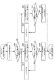
図13に示すように、ドライバ校正制御DのステップS801において、制御装置40は、ドライバ35から比例電磁弁30に電流I(n)を所定時間流して、ステップをステップS802に移行させる。   As shown in FIG. 13, in step S801 of the driver calibration control D, the control device 40 causes a current I (n) to flow from the driver 35 to the proportional solenoid valve 30 for a predetermined time, and the process proceeds to step S802.

ステップS802において、制御装置40は、位置センサ26の検出値Pが変動したか否かを判定する。すなわち、制御装置40は、ドライバ35からの電流I(n)の電流値が比例電磁弁30を駆動させる最小電流値Imin以上か否かを判定する。
その結果、位置センサ26の検出値Pが変動したと判定した場合、すなわち、ドライバ35からの電流I(n)の電流値が比例電磁弁30を駆動させる最小電流値Imin以上であると判定した場合、制御装置40はステップをステップS803に移行させる。
一方、位置センサ26の検出値Pが変動していないと判定した場合、制御装置40はステップをステップS823に移行させる。
In step S802, the control device 40 determines whether or not the detection value P of the position sensor 26 has changed. That is, the control device 40 determines whether or not the current value of the current I (n) from the driver 35 is equal to or greater than the minimum current value Imin that drives the proportional solenoid valve 30.
As a result, when it is determined that the detection value P of the position sensor 26 has changed, that is, it is determined that the current value of the current I (n) from the driver 35 is equal to or greater than the minimum current value Imin that drives the proportional solenoid valve 30. In the case, the control device 40 shifts the step to step S803.
On the other hand, when determining that the detection value P of the position sensor 26 has not changed, the control device 40 shifts the step to step S823.

ステップS803において、制御装置40は、ドライバ35から比例電磁弁30に流す電流I(n)の電流値を所定値Ivだけ小さくした電流I(n+1)を所定時間流して、ステップをステップS804に移行させる。   In step S803, the control device 40 causes a current I (n + 1) obtained by reducing the current value of the current I (n) flowing from the driver 35 to the proportional solenoid valve 30 by a predetermined value Iv to flow for a predetermined time, and the process proceeds to step S804. Let

ステップS804において、制御装置40は、位置センサ26の検出値Pが変動していないか否かを判定する。
その結果、位置センサ26の検出値Pが変動していないと判定した場合、制御装置40はステップをステップS805に移行させる。
一方、位置センサ26の検出値Pが変動していると判定した場合、制御装置40はステップをステップS814に移行させる。
In step S804, the control device 40 determines whether or not the detection value P of the position sensor 26 has changed.
As a result, when it is determined that the detection value P of the position sensor 26 has not changed, the control device 40 shifts the step to step S805.
On the other hand, when it is determined that the detection value P of the position sensor 26 is changing, the control device 40 shifts the step to step S814.

ステップS805において、制御装置40は、最小電流値Iminを電流I(n)の電流値に設定して、ドライバ校正制御Dを終了する。   In step S805, the control device 40 sets the minimum current value Imin to the current value of the current I (n), and ends the driver calibration control D.

ステップS814において、制御装置40は、電流I(n)のnをn=n+1として、すなわち、電流I(n)の電流値を所定値Ivだけ小さくした電流I(n+1)を電流I(n)とし、新たな電流I(n)の電流値を所定値Ivだけ小さくするために、ステップをステップS803に移行させる。   In step S814, the control device 40 sets the current I (n) to n = n + 1, that is, the current I (n + 1) obtained by reducing the current value of the current I (n) by the predetermined value Iv is the current I (n). In order to reduce the current value of the new current I (n) by the predetermined value Iv, the step is shifted to step S803.

ステップS823において、制御装置40は、ドライバ35から比例電磁弁30に流す電流I(n)の電流値を所定値Ivだけ大きくした電流I(n+1)を所定時間流して、ステップをステップS804に移行させる。   In step S823, the control device 40 causes a current I (n + 1) obtained by increasing the current value of the current I (n) flowing from the driver 35 to the proportional solenoid valve 30 by the predetermined value Iv to flow for a predetermined time, and the process proceeds to step S804. Let

ステップS824において、制御装置40は、位置センサ26の検出値Pが変動しているか否かを判定する。
その結果、位置センサ26の検出値Pが変動していると判定した場合、制御装置40はステップをステップS825に移行させる。
一方、位置センサ26の検出値Pが変動していないと判定した場合、制御装置40はステップをステップS834に移行させる。
In step S824, the control device 40 determines whether or not the detection value P of the position sensor 26 is fluctuating.
As a result, when it is determined that the detection value P of the position sensor 26 has changed, the control device 40 shifts the step to step S825.
On the other hand, when determining that the detection value P of the position sensor 26 has not changed, the control device 40 shifts the step to step S834.

ステップS825において、制御装置40は、電流I(n+1)の電流値を最小電流値Iminに設定して、ドライバ校正制御Dを終了する。   In step S825, the control device 40 sets the current value of the current I (n + 1) to the minimum current value Imin, and ends the driver calibration control D.

ステップS834において、制御装置40は、電流I(n)のnをn=n+1として、すなわち、電流I(n)の電流値を所定値Ivだけ大きくした電流I(n+1)を電流I(n)とし、新たな電流I(n)の電流値を所定値Ivだけ大きくするために、ステップをステップS823に移行させる。   In step S834, the control device 40 sets n of the current I (n) to n = n + 1, that is, sets the current I (n + 1) obtained by increasing the current value of the current I (n) by a predetermined value Iv to the current I (n). In order to increase the current value of the new current I (n) by the predetermined value Iv, the step is shifted to step S823.

以下では、船舶100のアウトドライブ装置10の制御態様における自動校正機能と操船制御との関係について説明する。   Below, the relationship between the automatic calibration function and ship maneuvering control in the control mode of the outdrive device 10 of the ship 100 will be described.

制御装置40は、アウトドライブ装置10の制御信号を受信すると、それまでに校正開始信号を受信しているか否かを判定する。制御装置40は、既に校正開始信号を受信しており、かつ校正途中又は校正が正常に完了していない場合、アウトドライブ装置10の制御信号を無効とする。一方、制御装置40は、既に校正開始信号を受信していない場合、又は、校正開始信号を受信しているが校正が正常に完了している場合、校正開始信号を無効とする。   When receiving the control signal of the outdrive device 10, the control device 40 determines whether or not a calibration start signal has been received so far. The control device 40 invalidates the control signal of the outdrive device 10 when it has already received the calibration start signal and is in the middle of calibration or when calibration is not completed normally. On the other hand, the control device 40 invalidates the calibration start signal when the calibration start signal has not been received or when the calibration start signal has been received but the calibration has been normally completed.

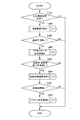
次に、図14を用いて上述の制御装置40の制御態様における自動校正機能と操船制御との関係について具体的に説明する。   Next, the relationship between the automatic calibration function and the ship maneuvering control in the control mode of the control device 40 will be described in detail with reference to FIG.

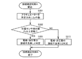
図14に示すように、ステップS901において、制御装置40は、アウトドライブ装置10の制御信号を受信すると、ステップをステップS902に移行させる。   As illustrated in FIG. 14, when the control device 40 receives a control signal from the outdrive device 10 in step S901, the control device 40 shifts the step to step S902.

ステップS902において、制御装置40は、アウトドライブ装置10の校正開始信号を受信済みか否かを判定する。
その結果、アウトドライブ装置10の校正開始信号を受信済みであると判定した場合、制御装置40はステップをステップS903に移行させる。
一方、アウトドライブ装置10の校正開始信号を受信していないと判定した場合、制御装置40はステップをステップS913に移行させる。
In step S902, the control device 40 determines whether or not the calibration start signal of the outdrive device 10 has been received.
As a result, when it is determined that the calibration start signal of the outdrive device 10 has been received, the control device 40 shifts the step to step S903.
On the other hand, when it determines with not having received the calibration start signal of the outdrive apparatus 10, the control apparatus 40 makes a step transfer to step S913.

ステップS903において、制御装置40は、アウトドライブ装置10の校正の実施途中であるか否かを判定する。
その結果、アウトドライブ装置10の校正の実施途中であると判定した場合、制御装置40はステップをステップS904に移行させる。
一方、アウトドライブ装置10の校正の実施途中でないと判定した場合、制御装置40はステップをステップ924に移行させる。
In step S903, the control device 40 determines whether or not calibration of the outdrive device 10 is in progress.
As a result, when determining that the calibration of the outdrive device 10 is in progress, the control device 40 shifts the step to step S904.
On the other hand, if it is determined that the calibration of the outdrive device 10 is not in progress, the control device 40 shifts the step to step 924.

ステップS904において、制御装置40は、アウトドライブ装置10の制御信号を無効として、自動校正の制御を継続する。すなわち、本実施形態の自動校正機能を有する船舶100は、アウトドライブ装置10の校正の実施途中にアウトドライブ装置10の制御が行えないように構成される。   In step S904, the control device 40 disables the control signal of the outdrive device 10 and continues control of automatic calibration. That is, the ship 100 having the automatic calibration function of the present embodiment is configured so that the outdrive device 10 cannot be controlled during the calibration of the outdrive device 10.

ステップS913において、制御装置40は、アウトドライブ装置10の制御信号を無効とする。すなわち、本実施形態の自動校正機能を有する船舶100は、アウトドライブ装置10の校正が実施されていない場合、アウトドライブ装置10の制御が行えないように構成される。   In step S <b> 913, the control device 40 invalidates the control signal of the outdrive device 10. That is, the ship 100 having the automatic calibration function of the present embodiment is configured so that the control of the outdrive device 10 cannot be performed when the outdrive device 10 is not calibrated.

ステップS924において、制御装置40は、アウトドライブ装置10の校正が完了しているか否かを判定する。
その結果、アウトドライブ装置10の校正が完了していると判定した場合、制御装置40はステップをステップS925に移行させる。
一方、アウトドライブ装置10の校正が完了していないと判定した場合、制御装置40はステップをステップS935に移行させる。
In step S924, the control device 40 determines whether the calibration of the outdrive device 10 has been completed.
As a result, when it is determined that the calibration of the outdrive device 10 is completed, the control device 40 shifts the step to step S925.
On the other hand, when it is determined that the calibration of the outdrive device 10 is not completed, the control device 40 shifts the step to step S935.

ステップS925において、制御装置40は、アウトドライブ装置10の校正開始信号を無効として、アウトドライブ装置10の制御を継続する。すなわち、本実施形態の自動校正機能を有する船舶100は、アウトドライブ装置10の校正が完了している場合、アウトドライブ装置10の制御中にアウトドライブ装置10の校正が実施できないように構成される。   In step S925, the control device 40 invalidates the calibration start signal of the outdrive device 10 and continues the control of the outdrive device 10. That is, the ship 100 having the automatic calibration function of the present embodiment is configured such that the calibration of the outdrive device 10 cannot be performed during the control of the outdrive device 10 when the calibration of the outdrive device 10 is completed. .

ステップS935において、制御装置40は、アウトドライブ装置10の制御信号を無効として、自動校正の制御を継続する。すなわち、本実施形態の自動校正機能を有する船舶100は、アウトドライブ装置10の校正が完了していない場合、アウトドライブ装置10の制御が行えないように構成される。   In step S935, the control device 40 disables the control signal of the outdrive device 10 and continues the automatic calibration control. That is, the ship 100 having the automatic calibration function of the present embodiment is configured so that the control of the outdrive device 10 cannot be performed when the calibration of the outdrive device 10 is not completed.

以上の如く、本発明に係る自動校正機能を有する船舶100は、油圧アクチュエータ20によって操舵するアウトドライブ装置10を具備する船舶100であって、作動油の方向を切り替える電磁弁である比例電磁弁30と比例電磁弁30を制御する制御装置40と、を具備し、制御装置40は、比例電磁弁30を制御してアウトドライブ装置10の校正を実施するとともに、校正の実施中に入力されたアウトドライブ装置10に対する制御信号を無効とするものである。
このように構成することにより、アウトドライブ装置10の校正実施前及び校正実施中にアウトドライブ装置10が操作されることがない。これにより、アウトドライブ装置10の校正完了前における操作を防止してアウトドライブ装置10の誤作動を抑制することができる。
As described above, the marine vessel 100 having the automatic calibration function according to the present invention is the marine vessel 100 including the outdrive device 10 that is steered by the hydraulic actuator 20, and is a proportional solenoid valve 30 that is an electromagnetic valve that switches the direction of hydraulic oil. And the control device 40 for controlling the proportional electromagnetic valve 30, and the control device 40 controls the proportional electromagnetic valve 30 to calibrate the outdrive device 10, and outputs the input input during the calibration. The control signal for the drive device 10 is invalidated.
By configuring in this way, the outdrive device 10 is not operated before and during the calibration of the outdrive device 10. Thereby, the operation before the completion of calibration of the outdrive device 10 can be prevented, and malfunction of the outdrive device 10 can be suppressed.

また、制御装置40は、アウトドライブ装置10の校正が正常に完了していない場合、アウトドライブ装置10に対する制御信号を無効とするものである。
このように構成することにより、アウトドライブ装置10の校正作業が異常終了した場合、アウトドライブ装置10が操作されることがない。これにより、アウトドライブ装置10の校正完了前における操作を防止してアウトドライブ装置10の誤作動を抑制することができる。
In addition, the control device 40 invalidates the control signal for the outdrive device 10 when the calibration of the outdrive device 10 is not normally completed.
With this configuration, when the calibration operation of the outdrive device 10 is abnormally terminated, the outdrive device 10 is not operated. Thereby, the operation before the completion of calibration of the outdrive device 10 can be prevented, and malfunction of the outdrive device 10 can be suppressed.

また、制御装置40は、アウトドライブ装置10の制御中に入力されたアウトドライブ装置10の校正信号を無効とするものである。
このように構成することにより、アウトドライブ装置10の制御中にアウトドライブ装置10の校正が実施されることがない。これにより、アウトドライブ装置10の校正完了前における操作を防止してアウトドライブ装置10の誤作動を抑制することができる。
Further, the control device 40 invalidates the calibration signal of the outdrive device 10 input during the control of the outdrive device 10.
With this configuration, the calibration of the outdrive device 10 is not performed during the control of the outdrive device 10. Thereby, the operation before the completion of calibration of the outdrive device 10 can be prevented, and malfunction of the outdrive device 10 can be suppressed.

また、制御装置40は、アウトドライブ装置10の校正が正常に完了した後にアウトドライブ装置10の校正を実施した場合、アウトドライブ装置10の校正が正常に完了するまでアウトドライブ装置10に対する制御信号を無効とするものである。
このように構成することにより、部品の交換等により再び校正を実施した場合でも、校正が正常に完了するまでアウトドライブ装置10が操作されることがない。これにより、アウトドライブ装置10の校正完了前における操作を防止してアウトドライブ装置10の誤作動を抑制することができる。
In addition, when the calibration of the outdrive device 10 is performed after the calibration of the outdrive device 10 is normally completed, the control device 40 transmits a control signal to the outdrive device 10 until the calibration of the outdrive device 10 is completed normally. It is invalid.
With this configuration, even when calibration is performed again by replacing parts, the outdrive device 10 is not operated until calibration is normally completed. Thereby, the operation before the completion of calibration of the outdrive device 10 can be prevented, and malfunction of the outdrive device 10 can be suppressed.

10 アウトドライブ装置
20 油圧アクチュエータ
30 比例電磁弁
40 制御装置
100 自動校正機能を有する船舶
DESCRIPTION OF SYMBOLS 10 Outdrive apparatus 20 Hydraulic actuator 30 Proportional solenoid valve 40 Control apparatus 100 Ship which has an automatic calibration function

Claims (4)

油圧アクチュエータによって操舵するアウトドライブ装置を具備する船舶であって、
作動油の方向を切り替える電磁弁と、
電磁弁を制御する制御装置と、を具備し、
制御装置は、
電磁弁を制御してアウトドライブ装置の校正を実施するとともに、校正の実施中に入力されたアウトドライブ装置に対する制御信号を無効とする自動校正機能を有する船舶。
A ship having an outdrive device that is steered by a hydraulic actuator,
A solenoid valve that switches the direction of hydraulic oil;
A control device for controlling the solenoid valve,
The control device
A vessel having an automatic calibration function that controls a solenoid valve to calibrate an outdrive device and invalidates a control signal input to the outdrive device during calibration.
前記制御装置は、
前記アウトドライブ装置の校正が正常に完了していない場合、アウトドライブ装置に対する制御信号を無効とする請求項1に記載の自動校正機能を有する船舶。
The control device includes:
2. A ship having an automatic calibration function according to claim 1, wherein when the calibration of the outdrive device is not normally completed, a control signal for the outdrive device is invalidated.
前記制御装置は、
前記アウトドライブ装置の制御中に入力されたアウトドライブ装置の校正信号を無効とする請求項1または請求項2に記載の自動校正機能を有する船舶。
The control device includes:
The marine vessel having an automatic calibration function according to claim 1 or 2, wherein a calibration signal of the outdrive device input during the control of the outdrive device is invalidated.
前記制御装置は、
前記アウトドライブ装置の校正が正常に完了した後にアウトドライブ装置の校正を実施した場合、アウトドライブ装置の校正が正常に完了するまでアウトドライブ装置に対する制御信号を無効とする請求項1から請求項3のいずれか一項に記載の自動校正機能を有する船舶。
The control device includes:
4. When the calibration of the outdrive device is performed after the calibration of the outdrive device is normally completed, the control signal for the outdrive device is invalidated until the calibration of the outdrive device is completed normally. A ship having the automatic calibration function according to any one of the above.
JP2012192524A 2012-08-31 2012-08-31 Ship with automatic calibration function Active JP5872422B2 (en)

Priority Applications (1)

Application Number Priority Date Filing Date Title
JP2012192524A JP5872422B2 (en) 2012-08-31 2012-08-31 Ship with automatic calibration function

Applications Claiming Priority (1)

Application Number Priority Date Filing Date Title
JP2012192524A JP5872422B2 (en) 2012-08-31 2012-08-31 Ship with automatic calibration function

Publications (2)

Publication Number Publication Date
JP2014046865A true JP2014046865A (en) 2014-03-17
JP5872422B2 JP5872422B2 (en) 2016-03-01

Family

ID=50606948

Family Applications (1)

Application Number Title Priority Date Filing Date
JP2012192524A Active JP5872422B2 (en) 2012-08-31 2012-08-31 Ship with automatic calibration function

Country Status (1)

Country Link
JP (1) JP5872422B2 (en)

Cited By (1)

* Cited by examiner, † Cited by third party
Publication number Priority date Publication date Assignee Title
US9908605B2 (en) 2014-01-30 2018-03-06 Yanmar Co., Ltd. Ship steering system for outdrive device

Citations (3)

* Cited by examiner, † Cited by third party
Publication number Priority date Publication date Assignee Title
JPH107090A (en) * 1996-06-26 1998-01-13 Yanmar Diesel Engine Co Ltd Hydraulic mechanism for propelling device for vessel
JP2001317503A (en) * 2000-04-03 2001-11-16 Husco Internatl Inc Automatic calibration method for solenoid-operated valve
JP2002021806A (en) * 2000-04-27 2002-01-23 Eaton Corp System and method of automatic calibration in hydraulic operating device

Patent Citations (3)

* Cited by examiner, † Cited by third party
Publication number Priority date Publication date Assignee Title
JPH107090A (en) * 1996-06-26 1998-01-13 Yanmar Diesel Engine Co Ltd Hydraulic mechanism for propelling device for vessel
JP2001317503A (en) * 2000-04-03 2001-11-16 Husco Internatl Inc Automatic calibration method for solenoid-operated valve
JP2002021806A (en) * 2000-04-27 2002-01-23 Eaton Corp System and method of automatic calibration in hydraulic operating device

Cited By (1)

* Cited by examiner, † Cited by third party
Publication number Priority date Publication date Assignee Title
US9908605B2 (en) 2014-01-30 2018-03-06 Yanmar Co., Ltd. Ship steering system for outdrive device

Also Published As

Publication number Publication date
JP5872422B2 (en) 2016-03-01

Similar Documents

Publication Publication Date Title
WO2015114781A1 (en) Ship steering system for outdrive device
JP2005212603A (en) Method of steering vessel propelling device
JP2007216911A (en) Steering device for outboard motor
JP5444123B2 (en) Steering system for out-drive device
JP5657484B2 (en) Ship drive system for out-drive device
JP2007253638A (en) Remote controlling device, and water craft
JP5944275B2 (en) Ship with automatic calibration function
JP4585570B2 (en) Power steering device and fluid volume flow sensitive steering method
JP5872422B2 (en) Ship with automatic calibration function
WO2014017401A1 (en) Steering device for ship
WO2018211809A1 (en) Steering apparatus and outboard motor unit
JP2010143321A (en) Outboard motor control device, and marine vessel including the same
JP6224937B2 (en) Steering device abnormality detection device and steering device with abnormality detection device
JP2017171263A (en) Ship
JP5130077B2 (en) Outboard motor and ship equipped with the same
US8015935B2 (en) Watercraft control apparatus
WO2017164394A1 (en) Ship
JP5827828B2 (en) Ship drive system for out-drive device
JP2009227022A (en) Steering device
WO2011148525A1 (en) Outdrive device and steering system for an outdrive device
JP2013014159A (en) Ship rudder fixing device, and ship operation method when ship rudder is fixed
EP2949573B1 (en) Ship steering system for out-drive device
JP5575548B2 (en) Outdrive device
CN205440831U (en) Boats and ships steering wheel electronic control system
JP2023031495A (en) Steering control device for vessel and steering control method for vessel

Legal Events

Date Code Title Description
A621 Written request for application examination

Free format text: JAPANESE INTERMEDIATE CODE: A621

Effective date: 20150223

TRDD Decision of grant or rejection written
A977 Report on retrieval

Free format text: JAPANESE INTERMEDIATE CODE: A971007

Effective date: 20151225

A01 Written decision to grant a patent or to grant a registration (utility model)

Free format text: JAPANESE INTERMEDIATE CODE: A01

Effective date: 20160105

A61 First payment of annual fees (during grant procedure)

Free format text: JAPANESE INTERMEDIATE CODE: A61

Effective date: 20160113

R150 Certificate of patent or registration of utility model

Ref document number: 5872422

Country of ref document: JP

Free format text: JAPANESE INTERMEDIATE CODE: R150

R250 Receipt of annual fees

Free format text: JAPANESE INTERMEDIATE CODE: R250

S533 Written request for registration of change of name

Free format text: JAPANESE INTERMEDIATE CODE: R313533

R350 Written notification of registration of transfer

Free format text: JAPANESE INTERMEDIATE CODE: R350