JP2014040742A - Attachment for civil engineering or construction work - Google Patents
Attachment for civil engineering or construction work Download PDFInfo
- Publication number
- JP2014040742A JP2014040742A JP2012183905A JP2012183905A JP2014040742A JP 2014040742 A JP2014040742 A JP 2014040742A JP 2012183905 A JP2012183905 A JP 2012183905A JP 2012183905 A JP2012183905 A JP 2012183905A JP 2014040742 A JP2014040742 A JP 2014040742A
- Authority
- JP
- Japan
- Prior art keywords
- hydraulic
- hydraulic oil
- attachment
- generator
- circuit
- Prior art date
- Legal status (The legal status is an assumption and is not a legal conclusion. Google has not performed a legal analysis and makes no representation as to the accuracy of the status listed.)
- Granted
Links
Images


Landscapes
- Fluid-Pressure Circuits (AREA)
Abstract
Description
本発明は、油圧ショベルやバックホー等の土木又は建築機械のアームの先端に取り付けられる土木又は建築作業用アタッチメントに関するものである。 TECHNICAL FIELD The present invention relates to civil engineering such as a hydraulic excavator and a backhoe, or a civil engineering or building work attachment attached to the tip of an arm of a construction machine.
油圧ショベル等の自走式作業台車のアームに取り付けられて、各種の作業を行う土木又は建築作業用アタッチメント(以下、単にアタッチメントと称する)が知られている。
例えばこの種のアタッチメントには、建築物のコンクリートを破壊したり小割りするもの、天然の岩盤を掘削したり小割りするもの、ガレキや材木等を掴むもの、篩機能を備えたもの等がある。
2. Description of the Related Art There are known civil engineering or construction work attachments (hereinafter simply referred to as attachments) that are attached to an arm of a self-propelled work carriage such as a hydraulic excavator and perform various operations.
For example, this type of attachment includes those that destroy or split concrete in buildings, those that excavate or split natural rock, those that grab rubble or timber, and those that have a sieve function. .
これらはいずれも油圧モータや、油圧シリンダー等の油圧アクチェータを備え、油圧ショベル等が備えた油圧発生装置から作動油の供給を受けて動作する。 Each of these includes a hydraulic actuator such as a hydraulic motor and a hydraulic cylinder, and operates by receiving hydraulic oil supplied from a hydraulic pressure generator provided in the hydraulic excavator or the like.
アタッチメントは、専ら作動油の油圧によって動作されるから、主たる機能を果たすためには、電気機器は不要である。そのためアタッチメントは、一般に給電線を有していない。
しかしながら実際にアタッチメントを使用して作業を行う状況を考えたとき、アタッチメントに電気機器が搭載されていれば便利であり、作業効率の向上が見込まれる。
たとえば、夜間に作業を行う場合を想定すると、建築作業用アタッチメントにサーチライトが搭載されていることが望ましい。アタッチメントを使用して細かい作業を行う場合には、アタッチメントにビデオカメラが搭載されていると便利である。
Since the attachment is operated exclusively by the hydraulic pressure of the hydraulic oil, no electrical equipment is required to perform the main function. Therefore, the attachment generally does not have a power supply line.
However, when considering a situation in which work is actually performed using an attachment, it is convenient if an electrical device is mounted on the attachment, and improvement in work efficiency is expected.
For example, assuming that the work is performed at night, it is desirable that a searchlight is mounted on the building work attachment. When performing detailed work using the attachment, it is convenient if the attachment is equipped with a video camera.
この様な場合、従来技術においては、本体たる油圧ショベル側からアタッチメント側に給電ケーブルを敷設し、これらの電気機器に対して給電せざるを得ない。 In such a case, in the prior art, a power feeding cable is laid from the hydraulic excavator side, which is the main body, to the attachment side, and power must be supplied to these electric devices.
前記した様に、アタッチメントに電気機器が搭載できれば便利であるが、アタッチメントは、要求される作業に応じて特殊な動作をさせるものであり、電気機器が全く不要である場合も少なくない。即ちアタッチメントには、電気機器を搭載するメリットのあるものと、メリットが全く無いものがある。
またアタッチメントが取り付けられる油圧ショベルは、汎用品であり、本来的な機能を発揮させるためには給電ケーブルは不要であり、且つ前記した様に、電気機器を搭載するメリットが無い場合も多いから、工場からの出荷時に、予め給電用の給電ケーブルを敷設しておくのは無駄が多い。そのため電気機器を搭載するためには、油圧ショベルに給電ケーブルを後付けする必要があり、面倒である。即ち油圧ショベル等は、長いアームを有し、アタッチメントは、アームの先端に取り付けられるから、給電ケーブルは長いアームに沿って敷設する必要があり、取り付けが面倒である。
As described above, it is convenient if an electrical device can be mounted on the attachment. However, the attachment causes a special operation according to a required operation, and the electrical device is often unnecessary. In other words, there are attachments that have the merit of mounting electrical equipment and those that have no merit at all.
In addition, the hydraulic excavator to which the attachment is attached is a general-purpose product, and a power supply cable is not necessary to demonstrate its original function, and as mentioned above, there are many cases where there is no merit of mounting electrical equipment, It is wasteful to lay a power supply cable for power supply in advance at the time of shipment from the factory. Therefore, in order to mount an electric device, it is necessary to attach a power supply cable to the hydraulic excavator, which is troublesome. That is, a hydraulic excavator or the like has a long arm, and the attachment is attached to the tip of the arm. Therefore, it is necessary to lay the power supply cable along the long arm, and the attachment is troublesome.
また油圧ショベルのアームは、当然に動くものであるのに対し、給電ケーブルは、油圧配管に比べて強度が低い。そのため油圧ショベルのアームに対して安易に給電ケーブルを敷設すると、給電ケーブルが切れやすい。またアタッチメントは、屋外で使用され、雨や水が掛かる場合が多ので、漏電の危険がある。この様に、油圧ショベルのアームに給電ケーブルを敷設するのは問題が多く、敷設作業には相当の注意を払う必要がある。 The arm of the hydraulic excavator naturally moves, whereas the power supply cable has lower strength than the hydraulic piping. For this reason, if the power supply cable is easily laid on the arm of the hydraulic excavator, the power supply cable is easily cut. Also, attachments are used outdoors and are often exposed to rain or water, so there is a risk of electrical leakage. Thus, laying the power supply cable on the arm of the excavator has many problems, and considerable care must be taken in the laying work.
そこで本発明は、従来技術の上記した問題点に注目し、アームに給電ケーブルを敷設することなく、電気機器に対して給電することができるアタッチメントを提供することを目的とする。 Therefore, the present invention focuses on the above-described problems of the prior art, and an object of the present invention is to provide an attachment that can supply power to an electric device without laying a power supply cable on an arm.
上記した課題を解決するための請求項1に記載の発明は、油圧発生装置とアームを有する自走式作業台車の、前記アームに取り付けられて使用される土木又は建築作業用アタッチメントであって、前記自走式作業台車側の油圧発生装置から作動油の供給を受けて動作する油圧アクチェータと、当該油圧アクチェータに作動油を供給及び/又は排出する作動油給排出配管を備えた土木又は建築作業用アタッチメントにおいて、作動油を通過させることによって発電する油圧発電機と蓄電池とを有し、当該油圧発電機が作動油給排出配管の一部に設けられていて作動油給排出配管を通過する作動油によって発電され、発電された電気が前記蓄電池に蓄電されることを特徴とする土木又は建築作業用アタッチメントである。 Invention of Claim 1 for solving an above-mentioned subject is a civil engineering or construction work attachment attached to the arm of a self-propelled work cart having a hydraulic pressure generator and an arm, Civil engineering or building work provided with a hydraulic actuator that operates by receiving hydraulic oil supplied from the hydraulic generator on the self-propelled work carriage side, and hydraulic oil supply / discharge piping that supplies and / or discharges hydraulic oil to the hydraulic actuator The hydraulic attachment has a hydraulic generator that generates electricity by passing hydraulic oil and a storage battery, and the hydraulic generator is provided in a part of the hydraulic oil supply / discharge pipe and passes through the hydraulic oil supply / discharge pipe It is a civil engineering or construction work attachment characterized in that the electricity generated by oil is stored in the storage battery.
本発明の建築作業用アタッチメントでは、作動油を通過させることによって発電する油圧発電機を有し、作動油給排出配管を通過する作動油によって発電される。即ち本発明の建築作業用アタッチメントでは、アタッチメント側で電気を起こすので、本体側(自走式作業台車側)から給電する必要がなく、アームに給電ケーブルを敷設する必要がない。
また発電は、間欠的なものとならざるを得ないが、本発明では、アタッチメント側に蓄電池があり、当該蓄電池に発電された電気が蓄電されるので、電気機器を連続的に使用することができる。
本発明で言う「作動油給排出配管」には、作動油が往復する配管と、一方方向にしか流れない配管の双方を含む。即ち油圧アクチェータに対して作動油を供給するのみの配管や、油圧アクチェータから作動油が戻るのみの配管も、「作動油給排出配管」である。
The construction work attachment according to the present invention has a hydraulic power generator that generates electric power by allowing hydraulic oil to pass therethrough, and generates electric power using the hydraulic oil that passes through the hydraulic oil supply / discharge pipe. That is, in the construction work attachment according to the present invention, electricity is generated on the attachment side, so there is no need to supply power from the main body side (self-propelled work carriage side), and there is no need to lay a power supply cable on the arm.
In addition, power generation must be intermittent. However, in the present invention, there is a storage battery on the attachment side, and electricity generated by the storage battery is stored. it can.
The “hydraulic oil supply / discharge piping” referred to in the present invention includes both piping in which hydraulic oil reciprocates and piping that flows only in one direction. That is, a pipe that only supplies hydraulic oil to the hydraulic actuator and a pipe that only returns hydraulic oil from the hydraulic actuator are also “hydraulic oil supply / discharge pipes”.
請求項2に記載の発明は、油圧発電機をバイパスするバイパス流路と、バイパス流路を流れる作動油の流量を増減させて油圧発電機と油圧アクチェータとの間の圧力を規制するバイパス流路調節手段とを備え、油圧アクチェータ側から油圧発電機の取り付け部位を通過して油圧発生装置側に作動油が戻る際に、油圧アクチェータ側の圧力が一定以上に上昇することを阻止することを特徴とする請求項1に記載の土木又は建築作業用アタッチメントである。 According to a second aspect of the present invention, there is provided a bypass passage for bypassing the hydraulic generator, and a bypass passage for regulating the pressure between the hydraulic generator and the hydraulic actuator by increasing or decreasing the flow rate of the hydraulic oil flowing through the bypass passage. Adjusting means, and prevents the hydraulic actuator side pressure from rising above a certain level when the hydraulic oil returns from the hydraulic actuator side to the hydraulic pressure generator side through the hydraulic generator mounting site. The civil engineering or building work attachment according to claim 1.
作動油給排出配管は、多くの場合、弁の切替えによって作動油の流れ方向が変わる。即ち、作動油の供給側を中心として考えた場合、自走式作業台車の油圧発生装置側から、アタッチメントの油圧アクチェータに向かって流れる往き側流れで作動油が流れる場合と、アタッチメントの油圧アクチェータ側から自走式作業台車の油圧発生装置側に流れる戻り側流れで作動油が流れる場合がある。
ここで問題となるのは、戻り側流れの場合である。即ち通常、戻り側流れの場合、作動油給排出配管は、油圧発生装置のタンク側に繋がることとなり、理論的には、作動油給排出配管の末端は、開放されて無圧状態となる。
これに対して作動油給排出配管に油圧発電機を取り付けると、油圧発電機を通過する際に流路抵抗が生じ、戻り側流れの場合に油圧アクチェータに背圧が掛かる。ここで、通常、油圧アクチェータは、作動油の排出側に大きな背圧が掛かることを想定せずに設計されているから、作動油の排出側に大きな背圧が掛かると、油圧アクチェータの動作が不安定になる場合がある。
そこで本発明では、油圧発電機をバイパスするバイパス流路を設け、油圧アクチェータ側の圧力が一定以上となった場合にバイパス流路を開いて、油圧アクチェータに過度の背圧が掛かることを防止することとした。
In many cases, the hydraulic oil supply and discharge piping changes the flow direction of the hydraulic oil by switching the valve. In other words, when the hydraulic oil supply side is considered as the center, the hydraulic oil flows from the hydraulic generator side of the self-propelled work carriage toward the hydraulic actuator of the attachment, and the hydraulic actuator side of the attachment In some cases, hydraulic fluid flows in the return-side flow that flows to the hydraulic pressure generator side of the self-propelled work carriage.
The problem here is the case of the return flow. That is, normally, in the case of the return side flow, the hydraulic oil supply / discharge pipe is connected to the tank side of the hydraulic pressure generator, and theoretically, the end of the hydraulic oil supply / discharge pipe is opened to be in a non-pressure state.
On the other hand, when a hydraulic generator is attached to the hydraulic oil supply / discharge pipe, flow path resistance is generated when passing through the hydraulic generator, and back pressure is applied to the hydraulic actuator in the case of a return side flow. Here, since the hydraulic actuator is normally designed without assuming that a large back pressure is applied to the hydraulic oil discharge side, if the hydraulic oil discharge side is subjected to a large back pressure, the hydraulic actuator operates. May become unstable.
Therefore, in the present invention, a bypass flow path that bypasses the hydraulic power generator is provided, and when the pressure on the hydraulic actuator side exceeds a certain level, the bypass flow path is opened to prevent excessive back pressure from being applied to the hydraulic actuator. It was decided.
請求項3に記載の発明は、送信機又は受信機の少なくともいずれかを備え、送信機又は受信機の少なくともいずれかは蓄電池又は油圧発電機から電力供給を受けて動作することを特徴とする請求項1又は2に記載の土木又は建築作業用アタッチメントである。
The invention according to
本発明の建築作業用アタッチメントは、送信機又は受信機の少なくともいずれかを備えているので、無線操作によって電気機器を動作させることができる。そのため建築作業用アタッチメントを操作するための信号線(電気配線)や、信号用の油圧配管(パイロット配管)を減らすことができる。 Since the attachment for construction work of the present invention includes at least one of a transmitter and a receiver, the electric device can be operated by wireless operation. Therefore, it is possible to reduce signal lines (electrical wiring) for operating the building work attachment and signal hydraulic piping (pilot piping).
請求項4に記載の発明は、油圧アクチェータを制御する制御弁を有し、当該制御弁は無線信号によって弁体を動作させることが可能であり、当該制御弁を動作させる電力が蓄電池又は油圧発電機から供給されることを特徴とする請求項1乃至3のいずれかに記載の土木又は建築作業用アタッチメントである。 The invention according to claim 4 has a control valve for controlling the hydraulic actuator, the control valve can operate the valve body by a radio signal, and the electric power for operating the control valve is a storage battery or hydraulic power generation. The civil engineering or building work attachment according to any one of claims 1 to 3, wherein the attachment is supplied from a machine.
従来技術においては、アタッチメントに設けられた油圧アクチェータを制御する為の制御弁は、例えば油圧ショベルの首振り用の制御弁が流用されるが、油圧アクチェータの数が複数である場合には、新たな制御弁を設けたり、新たな配管や信号線、信号配管(パイロット配管)等を敷設する必要が生じる。
これに対して請求項4に記載の発明は、油圧アクチェータ側に油圧アクチェータを制御する制御弁を設け、この制御弁は無線によって動作させることができるから、新たな配管や信号線や信号配管等を敷設する必要が無い。
In the prior art, for example, a control valve for swinging a hydraulic excavator is used as a control valve for controlling the hydraulic actuator provided in the attachment. However, when there are a plurality of hydraulic actuators, a new control valve is used. It is necessary to provide a simple control valve or to lay a new pipe, signal line, signal pipe (pilot pipe) or the like.
On the other hand, the invention according to claim 4 is provided with a control valve for controlling the hydraulic actuator on the hydraulic actuator side, and this control valve can be operated wirelessly, so that a new pipe, signal line, signal pipe, etc. There is no need to lay.
請求項5に記載の発明は、油圧発電機は、作動油が通過するキャビティと、永久磁石と、コイルとを有し、前記キャビテイ内に永久磁石が回転可能に配され、キャビティの外側に前記コイルが設けられていることを特徴とする請求項1乃至4のいずれかに記載の土木又は建築作業用アタッチメントである。 According to a fifth aspect of the present invention, the hydraulic power generator includes a cavity through which hydraulic fluid passes, a permanent magnet, and a coil, and the permanent magnet is rotatably disposed in the cavity, and the hydraulic generator is disposed outside the cavity. The civil engineering or building work attachment according to any one of claims 1 to 4, wherein a coil is provided.
本発明によると、キャビテイ内を高圧の作動油が通過することとなるが、高圧にさらされるのは、永久磁石であるから、油圧発電機が壊れることがない。 According to the present invention, the high-pressure hydraulic oil passes through the cavity, but since the permanent magnet is exposed to the high pressure, the hydraulic power generator is not broken.
請求項6に記載の発明は、油圧発電機の取り付け位置は、油圧アクチェータに対して作動油を供給する供給路として機能する場合と、油圧アクチェータから作動油を排出する供給路として機能する場合がある往復路であることを特徴とする請求項1乃至5のいずれかに記載の土木又は建築作業用アタッチメントである。 According to the sixth aspect of the present invention, the mounting position of the hydraulic generator may function as a supply path for supplying hydraulic oil to the hydraulic actuator, or may function as a supply path for discharging hydraulic oil from the hydraulic actuator. The civil engineering or building work attachment according to any one of claims 1 to 5, which is a round-trip path.
本発明によると、作動油の往復で発電に寄与する。 According to the present invention, the hydraulic oil reciprocates and contributes to power generation.
本発明の土木又は建築作業用アタッチメントは、アームに給電ケーブルを敷設することなく、アタッチメント側に給電することができる。そのため本発明の土木又は建築作業用アタッチメントは、電気機器を利用した作業を行わしめることができる。 The civil engineering or building work attachment of the present invention can supply power to the attachment side without laying a power supply cable on the arm. Therefore, the civil engineering or building work attachment of the present invention can perform work using electric equipment.
以下さらに本発明の実施形態について説明する。
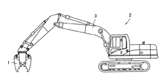
本実施形態の建築作業用アタッチメント1は、図2に示すように油圧ショベル(自走式作業台車)2のアーム3の先端に取り付けられ、主として建築物を解体したり、コンクリートを破砕する用途に使用されるものである。
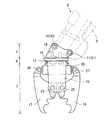
建築作業用アタッチメント1は、図1の様に、油圧ショベル2のアーム3に取り付けられる取り付け用ブラケット部5と、回転座部6と、破砕アーム部7によって構成されている。
取り付け用ブラケット部5は、図1の様に、二つのピン挿通孔10,11を有している。
Embodiments of the present invention will be further described below.
The construction work attachment 1 of this embodiment is attached to the tip of an
As shown in FIG. 1, the construction work attachment 1 includes an
As shown in FIG. 1, the mounting
回転座部6は、固定側部材12と回動側部材13を有している。回動側部材13は、固定側部材12に対して回転可能である。また固定側部材12と回動側部材13の間には図示しない歯車列が内蔵されている。そして当該歯車列に、油圧モータ15が係合しており、油圧モータ15を回転させることによって、回動側部材13が固定側部材12に対して回転する。
本実施形態では、回転座部6の固定側部材12が取り付け用ブラケット部5に一体的に固定されており、前記した油圧モータ15を回転させることによって、回動側部材13が回転する。
The rotary seat portion 6 includes a fixed
In the present embodiment, the fixed
破砕アーム部7は、アームブラケット16と、二つの破砕アーム片17,18及び油圧シリンダー20によって構成されている。
二つの破砕アーム片17,18は、いずれもその一部が、ピン23,25によってアームブラケット16に軸止されており、他の一部が、ピン26,27によって油圧シリンダー20に軸止されている。
そのため油圧シリンダー20を伸縮させると、二つの破砕アーム片17,18は、ピン23,25を中心として揺動し、開閉動作が行われる。
The crushing
A part of each of the two crushing
Therefore, when the
建築作業用アタッチメント1は、取り付け用ブラケット部5が、ピン30,31を介して油圧ショベル2のアーム3の先端に取り付けられており、油圧モータ15を回転させることによって、破砕アーム部7が回転し、破砕アーム片17,18の姿勢が変更される。 また油圧シリンダー20を伸ばすことによって二つの破砕アーム片17,18の先端側が開き、油圧シリンダー20を収縮させることによって二つの破砕アーム片17,18の先端側が閉じる。
In the construction work attachment 1, the mounting
次に、建築作業用アタッチメント1の油圧回路(以下、アタッチメント側油圧回路)40及び油圧ショベル2側の油圧回路(以下、ショベル側油圧回路)41について説明する。
Next, the hydraulic circuit (hereinafter, attachment-side hydraulic circuit) 40 of the building work attachment 1 and the hydraulic circuit (hereinafter, excavator-side hydraulic circuit) 41 on the
本実施形態で採用するアタッチメント側油圧回路40は、図3に図示する全ての配管が、油圧アクチェータたる油圧モータ15と油圧シリンダー20に作動油を供給・排出する作動油給排出配管であり、且つ往復路である。アタッチメント側油圧回路40は、大きく油圧モータ駆動回路42と、油圧シリンダー駆動回路43と、回路切替え手段45と、発電流路46によって構成されている。
回路切替え手段45は、公知の2位置6ポート電磁弁であり、第1作動油給排ポートa、第2作動油給排ポートb、モータ側第1給排ポートe、モータ側第2給排ポートf、シリンダ側第1給排ポートc、シリンダ側第2給排ポートdを有している。
そして弁体(図示せず)が第1位置にあるときは、第1作動油給排ポートaとシリンダ側第1給排ポートcとが繋がり、第2作動油給排ポートbとシリンダ側第2給排ポートdとが繋がる。弁体(図示せず)が第2位置にあるときは、第1作動油給排ポートaと、モータ側第1給排ポートeとが繋がり、第2作動油給排ポートbとモータ側第2給排ポートfとが繋がる。
In the attachment-side
The circuit switching means 45 is a known 2-position 6-port solenoid valve, and includes a first hydraulic oil supply / discharge port a, a second hydraulic oil supply / discharge port b, a motor-side first supply / discharge port e, and a motor-side second supply / discharge. It has a port f, a cylinder side first supply / discharge port c, and a cylinder side second supply / discharge port d.
When the valve body (not shown) is in the first position, the first hydraulic oil supply / discharge port a and the cylinder side first supply / discharge port c are connected, and the second hydraulic oil supply / discharge port b and the cylinder side first port are connected. Two supply / discharge ports d are connected. When the valve body (not shown) is in the second position, the first hydraulic oil supply / discharge port a and the motor side first supply / discharge port e are connected, and the second hydraulic oil supply / discharge port b and the motor side first port are connected. 2 is connected to the supply / discharge port f.
回路切替え手段45は、前記した様に電磁弁であるから、付属する電磁弁ソレノイド47によって弁体(図示せず)が動作する。また後記する様に、建築作業用アタッチメント1は受信機48を備えており、受信機48の信号によって、電磁弁ソレノイド47が動作する。即ち回路切替え手段45は、油圧アクチェータ(油圧モータ15と油圧シリンダー20)を制御する制御弁であって、無線信号によって弁体を動作させることが可能なものである。
Since the circuit switching means 45 is an electromagnetic valve as described above, a valve element (not shown) is operated by the attached
油圧モータ駆動回路42は、前記した回路切替え手段45と油圧モータ15とを接続する作動油給排出配管である。油圧モータ15は、第1ポート50と第2ポート51とを有する。そして第1ポート50から第2ポート51に作動油が流れると正回転し、第2ポート51から第1ポート50に作動油が流れると逆回転する。
油圧モータ駆動回路42は、回路切替え手段45のモータ側第1給排ポートeと油圧モータ15の第1ポート50とを接続するモータ駆動第1配管52と、回路切替え手段45のモータ側第2給排ポートfと、油圧モータ15の第2ポート51とを接続するモータ駆動第2配管53によって構成されている。
また本実施形態では、油圧モータ15の第1ポート50近傍と、第2ポート51の近傍に速度調節部材56a,56bが設けられている。速度調節部材56a,56bは、油圧回路に普通に使用されるものであり、可変絞り54と逆止弁59によって構成されている。
The hydraulic
The hydraulic
In the present embodiment,
油圧シリンダー駆動回路43は、前記した回路切替え手段45と油圧シリンダー20とを接続する作動油給排出配管である。油圧シリンダー20は、第1ポート57と第2ポート58とを有する。そして第1ポート57から作動油が供給され、第2ポート58から作動油が排出されるとロッド21が伸長する。逆に第2ポート58から作動油が供給され、第1ポート57から作動油が排出されるとロッド21が収縮する。
油圧シリンダー駆動回路43は、回路切替え手段45のシリンダ側第1給排ポートcと油圧シリンダー20の第1ポート57とを接続するシリンダ駆動第1配管64と、回路切替え手段45のシリンダ側第2給排ポートdと、油圧シリンダー20の第2ポート58とを接続するシリンダ駆動第2配管69によって構成されている。
The hydraulic
The hydraulic
回路切替え手段45の、第1作動油給排ポートa及び第2作動油給排ポートb側に目を移すと、第1作動油給排ポートa及び第2作動油給排ポートbはいずれもカプラ60,61に接続されている。
また第2作動油給排ポートbとカプラ61との間を接続する第2給排ポート側作動油給排出配管62に、発電流路46が設けられている。発電流路46は、油圧発電機70が介在された流路である。なお第2給排ポート側作動油給排出配管62は、作動油給排出配管であり、且つ往復路である。
発電流路46は、図3の様に、油圧発電機70を通過する主流路65と、油圧発電機70をバイパスするバイパス流路66とを備えている。
そしてバイパス流路66には、バイパス流路調節手段71と、逆止弁72とが設けられている。逆止弁72は、バイパス流路調節手段71よりもカプラ61側に設けられており、カプラ61から回路切替え手段45側に至る流れを遮断し、回路切替え手段45からカプラ61側に戻る流れを許容する。
When the eyes are moved to the first hydraulic oil supply / discharge port a and the second hydraulic oil supply / discharge port b side of the circuit switching means 45, both the first hydraulic oil supply / discharge port a and the second hydraulic oil supply / discharge port b are provided. The
In addition, a power
As shown in FIG. 3, the
The
バイパス流路調節手段71は、具体的にはリリーフ弁であり、回路切替え手段45の第2作動油給排ポートbと油圧発電機70との間の圧力を検知し、この圧力が一定値となる様に開度が調節されるものである。なおバイパス流路調節手段71は、前記した様にリリーフ弁であるから、回路切替え手段45と油圧発電機70との圧力が、一定値よりも低い場合には、全閉状態となっている。
The bypass flow path adjusting means 71 is specifically a relief valve, and detects the pressure between the second hydraulic oil supply / discharge port b of the circuit switching means 45 and the
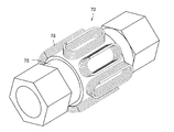
油圧発電機70は、例えば図4、図5に示す様な構造であり、管体75のキャビティ76内に永久磁石77が設けられ、さらに管体75の外側にコイル78が6個配されたものである。
即ち管体75は、アルミ、ステンレス、樹脂等の磁化されにくい素材で作られたものであり、両端が開口し、内部にキャビティ76を有するものである。またキャビティ76内には、永久磁石77を回転可能に支持する支持部材79a,79bが設けられている。
永久磁石77には、図の様に、表面に螺旋形状80や、羽根形状が形成されている。永久磁石77は回転子として機能するものであり、その両端が支持部材79a,79bに支持され、管体75のキャビティ76内に回転可能に保持されている。
なお永久磁石77は、表面にN極とS極が交互に現れる様に着磁されている。
6個のコイル78は、いずれも図示しないボビンに巻かれている。なおコイル78の個数は任意である。
The
That is, the
As shown in the figure, the
The
Each of the six
油圧発電機70の内部に作動油が通過すると、キャビティ76内で永久磁石77が回転し、周囲のコイル78に誘導電流を発生させる。
When hydraulic oil passes through the
次にショベル側油圧回路41について説明する。
ショベル側油圧回路41は、手動切替え弁81と、油圧発生装置82によって構成されている。
手動切替え弁81は、公知の3位置4ポート弁であり、第1作動油給排ポートA、第2作動油給排ポートB、アクチェータ側第1ポートC及びアクチェータ側第2ポートDを有している。
そして第1位置では、第1作動油給排ポートAとアクチェータ側第1ポートCが連通し、第2作動油給排ポートBとアクチェータ側第2ポートDとが連通する。
第2位置(ニュートラル位置)では、全てのポートが閉鎖される。
また第3位置では、第1位置と交差する方向に流路が変更され、具体的には、第1作動油給排ポートAとアクチェータ側第2ポートDとが連通する。また第2作動油給排ポートBとアクチェータ側第1ポートCとが連通する。
Next, the excavator side
The excavator side
The
In the first position, the first hydraulic oil supply / discharge port A and the actuator-side first port C communicate, and the second hydraulic oil supply / discharge port B and the actuator-side second port D communicate.
In the second position (neutral position), all ports are closed.
In the third position, the flow path is changed in a direction intersecting the first position. Specifically, the first hydraulic oil supply / discharge port A and the actuator-side second port D communicate with each other. The second hydraulic oil supply / discharge port B and the actuator side first port C communicate with each other.
また手動切替え弁81の、アクチェータ側第1ポートC、アクチェータ側第2ポートDは、それぞれカプラ83,84に接続されている。
Further, the actuator side first port C and the actuator side second port D of the
油圧発生装置82は、公知の油圧ユニットであり、作動油タンク73と、油圧ポンプ85と、戻り配管86及びリリーフ弁87によって構成されている。
即ち油圧ポンプ85の吐出側が手動切替え弁81の第1作動油給排ポートAに接続されている。また戻り配管86は、作動油タンク73と手動切替え弁81の第2作動油給排ポートBを繋ぐものである。
さらにリリーフ弁87は、油圧ポンプ85の吐出側と戻り配管86との間に設けられている。
The
That is, the discharge side of the
Furthermore, the
次に、アタッチメント側油圧回路40と、ショベル側油圧回路41との接続関係について説明する。
前記した様に、アタッチメント側油圧回路40には、カプラ60,61がある。またショベル側油圧回路41にもカプラ83,84がある。
そして本実施形態では油圧ショベル2側のカプラ83,84と、建築作業用アタッチメント1側のカプラ60,61との間が油圧ホース88a,88bによって接続されている。なおアタッチメント側油圧回路40と、ショベル側油圧回路41との間を接続する部材は任意であり、パイプを使用してもよい。
接続の結果、ショベル側油圧回路41にある手動切替え弁81の、アクチェータ側第1ポートCが、建築作業用アタッチメント1側の回路切替え手段45の第1作動油給排ポートaと接続されている。また手動切替え弁81のアクチェータ側第2ポートDが、回路切替え手段45の第2作動油給排ポートbと接続されている。
Next, the connection relationship between the attachment-side
As described above, the attachment-side
In the present embodiment, the
As a result of the connection, the actuator-side first port C of the
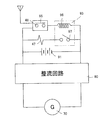
次に建築作業用アタッチメント1の電気回路について説明する(図6)。
建築作業用アタッチメント1では、整流回路90と、蓄電池91と、受信機48と、外部リレー93とを有している。受信機48は、所定の信号を受信することによって内部リレー95を通電状態にするものである。
本実施形態の建築作業用アタッチメント1は、前記した油圧発電機70で発電した電気を整流回路90で整流し、蓄電池91に蓄電することができる。
より具体的には、油圧発電機70の各コイル78が整流回路90に接続されて直流に整流される。そして整流回路90のプラス極と、蓄電池91のプラス極が接続され、さらに整流回路90のマイナス極と、蓄電池91のマイナス極が接続されている。
Next, the electrical circuit of the building work attachment 1 will be described (FIG. 6).
The construction work attachment 1 includes a
The construction work attachment 1 of the present embodiment can rectify the electricity generated by the
More specifically, each
さらに蓄電池91に対して、受信機48と、回路切替え手段45の電磁弁ソレノイド47が並列接続されている。
また受信機48には、外部リレー93のリレーソレノイド96が直列接続されている。また回路切替え手段45の電磁弁ソレノイド47には、外部リレー93の端子97が直列接続されている。
Furthermore, the
The
従って、受信機48が所定の信号を受信すると、受信機48の内部リレー95がオン状態となって外部リレー93のリレーソレノイド96に通電される。その結果、外部リレー93がオン状態となって回路切替え手段45の電磁弁ソレノイド47に通電され、回路切替え手段45の弁体が動く。
この様に本実施形態では、建築作業用アタッチメント1に搭載された電気機器たる受信機48と、回路切替え手段45と、外部リレー93の3者が、蓄電池91又は油圧発電機70から電力供給を受けて動作する。
Therefore, when the
As described above, in this embodiment, the
次に、本実施形態の建築作業用アタッチメント1の作用について説明する。
建築作業用アタッチメント1は、ショベル側油圧回路41から作動油の供給を受けて動作する。即ちショベル側油圧回路41の油圧ポンプ85を動作させ、手動切替え弁81を第1位置又は第3位置にすると、昇圧された作動油が、アタッチメント側油圧回路40に導入される。
またアタッチメント側油圧回路40に導入された作動油は、回路切替え手段45の切替え位置に応じて、油圧モータ15又は油圧シリンダー20に対して選択的に供給される。
即ち回路切替え手段45が第1位置にある場合には、作動油は油圧シリンダー20だけに導入される。
一方、回路切替え手段45が第2位置にある場合には、作動油は油圧モータ15だけに導入される。
Next, the effect | action of the construction work attachment 1 of this embodiment is demonstrated.
The construction work attachment 1 operates upon receiving hydraulic oil from the excavator side
The hydraulic oil introduced into the attachment-side
That is, when the circuit switching means 45 is in the first position, the hydraulic oil is introduced only into the
On the other hand, when the circuit switching means 45 is in the second position, the hydraulic oil is introduced only into the
本実施形態では、油圧モータ15の回転方向の切替えおよび、油圧シリンダー20の伸縮は、油圧ショベル2側の手動切替え弁81によって実施される。
即ち油圧ショベル2側の手動切替え弁81が第1位置にある場合は、油圧シリンダー20は伸びる。また油圧ショベル2側の手動切替え弁81が第1位置にある場合は、油圧モータ15に対して作動油が第1作動油給排ポートAから導入され、油圧モータ15は正回転する。
より詳細に説明すると、油圧ショベル2側の手動切替え弁81が第1位置にあり、建築作業用アタッチメント1の回路切替え手段45が第1位置にある場合には、油圧シリンダー20は伸び方向に動作する。
また油圧ショベル2側の手動切替え弁81が第1位置にあり、建築作業用アタッチメント1の回路切替え手段45が第2位置にある場合には、油圧モータ15は正回転する。
In the present embodiment, switching of the rotation direction of the
That is, when the
More specifically, when the
Further, when the
逆に、油圧ショベル2側の手動切替え弁81が第3位置にある場合は、油圧シリンダー20に対して作動油が第1作動油給排ポートAから導入され、油圧シリンダー20は縮む。また油圧ショベル2側の手動切替え弁81が第3位置にあり、建築作業用アタッチメント1回路切替え手段45が第2位置にある場合は、油圧モータ15は逆回転する。
より詳細に説明すると、油圧ショベル2側の手動切替え弁81が第3位置にあり、建築作業用アタッチメント1の回路切替え手段45が第1位置にある場合には、油圧シリンダー20は縮み方向に動作する。
また油圧ショベル2側の手動切替え弁81が第3位置にあり、建築作業用アタッチメント1の回路切替え手段45が第2位置にある場合には、油圧モータ15は逆回転する。
Conversely, when the
More specifically, when the
When the
建築作業用アタッチメント1の発電流路46に注目すると、油圧ショベル2側の手動切替え弁81が第1位置にある場合は、戻り側となり、作動油は建築作業用アタッチメント1側から油圧ショベル2側に向かって流れる。
一方、油圧ショベル2側の手動切替え弁81が第3位置にある場合は、往き側となり、作動油は油圧ショベル2側から建築作業用アタッチメント1側に向かって流れる。
When attention is paid to the power
On the other hand, when the
まず発電流路46に対して往き側に作動油が流れる場合を考えると、バイパス流路66の逆止弁72が閉鎖方向となるので、全ての作動油が油圧発電機70を通過し、内部の永久磁石77を回転させて発電を行う。
発電された電力は、整流回路90で整流され、さらに蓄電池91に蓄電される。そして必要に応じて、受信機48、外部リレー93、回路切替え手段45の電磁弁ソレノイド47で消費される。
First, considering the case where hydraulic oil flows to the forward side with respect to the power
The generated power is rectified by the
次に、発電流路46に対して戻り側に作動油が流れる場合を考えると、作動油の圧力は、油圧発電機70と、バイパス流路66とに掛かる。ここでバイパス流路66には、バイパス流路調節手段71たるリリーフ弁が設けられているので、リリーフ弁(バイパス流路調節手段71)が開放状態となる圧力未満であるならば、バイパス流路66は閉塞され、全ての作動油が油圧発電機70を通過し、内部の永久磁石77を回転させて発電を行う。
発電された電力は、整流回路90で整流され、さらに蓄電池91に蓄電される。そして必要に応じて、受信機48、外部リレー93、回路切替え手段45の電磁弁ソレノイド47で消費される。
Next, considering the case where hydraulic oil flows to the return side with respect to the power
The generated power is rectified by the
これに対して、油圧発電機70における圧力損失が増大し、油圧発電機70と回路切替え手段45との間が高圧状態となった場合、即ち、油圧モータ15又は油圧シリンダー20に過度に背圧が掛かった場合は、リリーフ弁(バイパス流路調節手段71)が開く。またバイパス流路66に設けられた逆止弁72は、作動油の流れに対して順方向であるから、作動油は逆止弁72を通過することができ、作動油はバイパス流路66にも流れる。その結果、油圧モータ15又は油圧シリンダー20に過度に背圧が掛かることは阻止される。
従って、アクチェータたる油圧モータ15や油圧シリンダー20は、不都合なく動作し、所定の仕事を行う。
On the other hand, when the pressure loss in the
Therefore, the
また本実施形態の建築作業用アタッチメント1には、前記した様に回路切替え手段45が搭載されており、回路切替え手段45は、電磁弁であって電気機器の一つである。
また本実施形態の建築作業用アタッチメント1には、受信機が搭載されており、当該受信機が受信した信号によって、回路切替え手段45が切り換えられる。従って、本実施形態の建築作業用アタッチメント1では、回路切替え手段45を動作させるための信号線や動力線、パイロット配管等が一切不要である。そのため、本実施形態の建築作業用アタッチメント1は配管接続や電気配線が簡便なもので足る。
In addition, as described above, the circuit switching means 45 is mounted on the building work attachment 1 of the present embodiment, and the circuit switching means 45 is an electromagnetic valve and is one of electric devices.
Moreover, the building work attachment 1 of this embodiment is equipped with a receiver, and the circuit switching means 45 is switched by a signal received by the receiver. Therefore, the construction work attachment 1 of this embodiment does not require any signal lines, power lines, pilot piping, or the like for operating the circuit switching means 45. Therefore, the construction work attachment 1 according to the present embodiment is sufficient for simple pipe connection and electrical wiring.
以上説明した実施形態では、建築作業用アタッチメント1に搭載する電気機器として、回路切替え手段45と受信機48及び外部リレー93を例示したが、本発明は、これらに限定されるものではない。他に考えられる電気機器として、テレビカメラや送信機、鉄材を吸着させる電磁石等が挙げられる。送信機は、例えばテレビカメラが撮影した映像を無線送信するものが考えられる。また建築作業用アタッチメント1の動作状況や設置位置を知らせる送信機を搭載することも可能である。即ち建築作業用アタッチメント1にGPS(Global Positioning System) に関連する装置を搭載してもよい。
さらに建築作業用アタッチメント1の使用時間を積算する計算機を搭載することも考えられる。
In the embodiment described above, the circuit switching means 45, the
Furthermore, it is also conceivable to install a computer that integrates the usage time of the building work attachment 1.
また各種のセンサーや電磁弁についても電気機器として採用可能である。
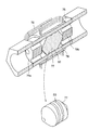
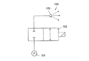
電磁弁を電気機器として採用する例として、散水機能付きの解体機が挙げられる。散水機能付きの解体機は、例えば図7に示すようなアクチェータ(シリンダー)99を動作させる油圧回路98を持つと共に、図8に示すような散水回路100を備えている。散水回路100は、散水ポンプ101と、電磁シャットオフ弁102と、散水ノズル103が直列的に接続されたものである。
そして例えば、油圧回路98のアクチェータ(シリンダー)99から油圧ショベル(自走式作業台車)2の油圧発生装置82側に作動油を戻す作動油給排出配管105に油圧発電機70等を設けて発電を行い、この電力で電磁シャットオフ弁102を動作させる。
Various sensors and solenoid valves can also be used as electrical devices.
An example of employing a solenoid valve as an electrical device is a dismantling machine with a watering function. The dismantling machine with a watering function has a
For example, a
以上説明した実施形態では、油圧発電機70を、回路切替え手段45とショベル側油圧回路41の間に設けたが、油圧発電機70の取り付け位置は任意である。例えば、油圧シリンダー駆動回路43のシリンダ駆動第1配管64又はシリンダ駆動第2配管69に油圧発電機70を設けてもよい。また油圧モータ駆動回路42の、モータ駆動第1配管52や、モータ駆動第2配管53に油圧発電機70を設けてもよい。
ただし油圧シリンダー駆動回路43及び油圧モータ駆動回路42は、選択的に作動油が流れるものであり、常時作動油が流れない。これに対して先の実施形態で示した回路切替え手段45とショベル側油圧回路41の間は、油圧シリンダー駆動回路43等に比べて作動油が流れる頻度が高いので、油圧発電機70を取り付ける位置として推奨される。
In the embodiment described above, the
However, in the hydraulic
また上記した実施形態で採用する油圧発電機70は、表面にN極とS極が交互に現れる様に着磁された永久磁石77を採用し、この永久磁石77を管体75のキャビティ76内に設けた構造を備えたものである。即ち上記した実施形態で採用する油圧発電機70は、永久磁石77そのものが回転子として機能し、キャビティ76内で永久磁石77が回転する。しかしながら本発明はこの構成に限定されるものではなく、樹脂や金属によって回転子のフレームを構成し、このフレームに永久磁石を装着した構造のものを採用してもよい。
樹脂等のフレームに永久磁石を装着する構造を採用する場合には、表面にN極とS極が交互に現れる様に配置することが望ましい。
本構成によると、回転子のフレームが回転することにより、フレームの周囲に装着された永久磁石が管体75のキャビティ76内で回転し、発電が行われる。
Further, the
When adopting a structure in which a permanent magnet is attached to a frame of resin or the like, it is desirable that the N pole and the S pole appear alternately on the surface.
According to this configuration, when the frame of the rotor rotates, the permanent magnet mounted around the frame rotates in the
1 建築作業用アタッチメント
2 油圧ショベル(自走式作業台車)
3 アーム
5 取り付け用ブラケット部
6 回転座部
7 破砕アーム部
15 油圧モータ
20 油圧シリンダー
40 アタッチメント側油圧回路
41 ショベル側油圧回路
42 油圧モータ駆動回路
43 油圧シリンダー駆動回路
45 回路切替え手段
46 発電流路
48 受信機
65 主流路
66 バイパス流路
70 油圧発電機
71 バイパス流路調節手段
72 逆止弁
73 作動油タンク
75 管体
76 キャビティ
77 永久磁石
78 コイル
81 手動切替え弁
82 油圧発生装置
85 油圧ポンプ
86 戻り配管
87 リリーフ弁
91 蓄電池
98 油圧回路
99 アクチェータ(シリンダー)
100 散水回路
1 Attachment for
DESCRIPTION OF
100 Watering circuit
Claims (6)
作動油を通過させることによって発電する油圧発電機と蓄電池とを有し、当該油圧発電機が作動油給排出配管の一部に設けられていて作動油給排出配管を通過する作動油によって発電され、発電された電気が前記蓄電池に蓄電されることを特徴とする土木又は建築作業用アタッチメント。 A civil engineering or building work attachment attached to the arm of a self-propelled work cart having a hydraulic pressure generating device and an arm, and supplying hydraulic oil from the hydraulic pressure generating device on the self-propelled work cart side In an attachment for civil engineering or construction work provided with a hydraulic actuator that operates by receiving and a hydraulic oil supply / discharge pipe that supplies and / or discharges hydraulic oil to the hydraulic actuator,
It has a hydraulic generator and a storage battery that generate electricity by passing hydraulic oil, and the hydraulic generator is provided in a part of the hydraulic oil supply / discharge pipe and is generated by the hydraulic oil passing through the hydraulic oil supply / discharge pipe. The civil engineering or construction work attachment, wherein the generated electricity is stored in the storage battery.
Priority Applications (1)
| Application Number | Priority Date | Filing Date | Title |
|---|---|---|---|
| JP2012183905A JP5698713B2 (en) | 2012-08-23 | 2012-08-23 | Attachment for civil engineering or construction work |
Applications Claiming Priority (1)
| Application Number | Priority Date | Filing Date | Title |
|---|---|---|---|
| JP2012183905A JP5698713B2 (en) | 2012-08-23 | 2012-08-23 | Attachment for civil engineering or construction work |
Publications (2)
| Publication Number | Publication Date |
|---|---|
| JP2014040742A true JP2014040742A (en) | 2014-03-06 |
| JP5698713B2 JP5698713B2 (en) | 2015-04-08 |
Family
ID=50393186
Family Applications (1)
| Application Number | Title | Priority Date | Filing Date |
|---|---|---|---|
| JP2012183905A Expired - Fee Related JP5698713B2 (en) | 2012-08-23 | 2012-08-23 | Attachment for civil engineering or construction work |
Country Status (1)
| Country | Link |
|---|---|
| JP (1) | JP5698713B2 (en) |
Cited By (5)
| Publication number | Priority date | Publication date | Assignee | Title |
|---|---|---|---|---|
| JP3205723U (en) * | 2016-05-30 | 2016-08-12 | 幅 朗 | Attachment for construction machine and attachment system for construction machine |
| JP2017036583A (en) * | 2015-08-10 | 2017-02-16 | 日本車輌製造株式会社 | Construction machine |
| JP2017180530A (en) * | 2016-03-28 | 2017-10-05 | 株式会社タグチ工業 | Regeneration system |
| JP2020133183A (en) * | 2019-02-17 | 2020-08-31 | オカダアイヨン株式会社 | Power generator in demolition attachment |
| WO2025127012A1 (en) * | 2023-12-11 | 2025-06-19 | 株式会社小松製作所 | Attachment management system, information terminal, and attachment management method |
Citations (7)
| Publication number | Priority date | Publication date | Assignee | Title |
|---|---|---|---|---|
| JPH11107311A (en) * | 1997-09-30 | 1999-04-20 | Yutani Heavy Ind Ltd | Power generator of construction machine |
| JP2003049809A (en) * | 2001-08-07 | 2003-02-21 | Hitachi Constr Mach Co Ltd | Pressure oil energy recovering device and construction machine with the same |
| JP2003182968A (en) * | 2001-12-20 | 2003-07-03 | Taguchi Kogyo:Kk | Attachment with electromagnet of construction machinery |
| JP2004225566A (en) * | 2003-01-20 | 2004-08-12 | Kobelco Contstruction Machinery Ltd | Device for preventing key from being left inserted for construction machine |
| JP2005254841A (en) * | 2004-03-09 | 2005-09-22 | Sumitomo (Shi) Construction Machinery Manufacturing Co Ltd | Electrical circuit of construction machinery |
| JP2006272229A (en) * | 2005-03-30 | 2006-10-12 | Nippon Pneumatic Mfg Co Ltd | Crusher with magnet |
| JP2011144555A (en) * | 2010-01-14 | 2011-07-28 | Kenji Kinoshita | Construction machine |
-
2012
- 2012-08-23 JP JP2012183905A patent/JP5698713B2/en not_active Expired - Fee Related
Patent Citations (7)
| Publication number | Priority date | Publication date | Assignee | Title |
|---|---|---|---|---|
| JPH11107311A (en) * | 1997-09-30 | 1999-04-20 | Yutani Heavy Ind Ltd | Power generator of construction machine |
| JP2003049809A (en) * | 2001-08-07 | 2003-02-21 | Hitachi Constr Mach Co Ltd | Pressure oil energy recovering device and construction machine with the same |
| JP2003182968A (en) * | 2001-12-20 | 2003-07-03 | Taguchi Kogyo:Kk | Attachment with electromagnet of construction machinery |
| JP2004225566A (en) * | 2003-01-20 | 2004-08-12 | Kobelco Contstruction Machinery Ltd | Device for preventing key from being left inserted for construction machine |
| JP2005254841A (en) * | 2004-03-09 | 2005-09-22 | Sumitomo (Shi) Construction Machinery Manufacturing Co Ltd | Electrical circuit of construction machinery |
| JP2006272229A (en) * | 2005-03-30 | 2006-10-12 | Nippon Pneumatic Mfg Co Ltd | Crusher with magnet |
| JP2011144555A (en) * | 2010-01-14 | 2011-07-28 | Kenji Kinoshita | Construction machine |
Cited By (6)
| Publication number | Priority date | Publication date | Assignee | Title |
|---|---|---|---|---|
| JP2017036583A (en) * | 2015-08-10 | 2017-02-16 | 日本車輌製造株式会社 | Construction machine |
| JP2017180530A (en) * | 2016-03-28 | 2017-10-05 | 株式会社タグチ工業 | Regeneration system |
| JP3205723U (en) * | 2016-05-30 | 2016-08-12 | 幅 朗 | Attachment for construction machine and attachment system for construction machine |
| JP2020133183A (en) * | 2019-02-17 | 2020-08-31 | オカダアイヨン株式会社 | Power generator in demolition attachment |
| JP7242330B2 (en) | 2019-02-17 | 2023-03-20 | オカダアイヨン株式会社 | Power generator in attachment |
| WO2025127012A1 (en) * | 2023-12-11 | 2025-06-19 | 株式会社小松製作所 | Attachment management system, information terminal, and attachment management method |
Also Published As
| Publication number | Publication date |
|---|---|
| JP5698713B2 (en) | 2015-04-08 |
Similar Documents
| Publication | Publication Date | Title |
|---|---|---|
| JP5698713B2 (en) | Attachment for civil engineering or construction work | |
| US10030355B2 (en) | Hydraulic control system for construction machine | |
| JP5815125B2 (en) | Hybrid excavator with hybrid actuator quick stop | |
| US20090031720A1 (en) | Hydraulic circuit for heavy equipment having variable control device | |
| JP2000273916A (en) | Hydraulic driving device for civil engineering/ construction machinery | |
| CN101634373A (en) | Pipe layer having swing speed adjustable system | |
| JP5097051B2 (en) | Hydraulic control equipment for construction machinery | |
| JP2010203036A (en) | Working machine driving circuit and working machine | |
| CN110905025B (en) | Hydraulic quick-change device and excavator | |
| US20120152368A1 (en) | Independent Metering Valve with Flow Limiter | |
| US7478531B2 (en) | Hydraulic circuit for heavy construction equipment | |
| GB2398364A (en) | Hydraulic system for excavator optional apparatus | |
| JP2011144555A (en) | Construction machine | |
| CN209856134U (en) | Quick-change control system and excavator | |
| JP6922115B2 (en) | Pile press-fitting device and pile press-fitting method | |
| EP3818217B1 (en) | Excavator boom mountable high pressure hydraulic tool including a hydraulic motor driven generator | |
| JP2008308944A (en) | Hydraulic control device of attachment of construction machine | |
| CN102704528A (en) | Excavator hydraulic system, control method for excavator hydraulic system and excavator | |
| CN210087737U (en) | Hydraulic system and rotary drilling rig | |
| CN201884369U (en) | Automatic hydraulic oil way switching device | |
| CN211774103U (en) | Self-defined action priority control hydraulic system and excavator hydraulic control system | |
| JP6282127B2 (en) | hydraulic unit | |
| JP2002030814A (en) | Structure demolition equipment | |
| JP2012067509A (en) | Hydraulic working machine and method of increasing output | |
| JP6466825B2 (en) | Hydraulic drive device and air conditioner for work machine |
Legal Events
| Date | Code | Title | Description |
|---|---|---|---|
| A621 | Written request for application examination |
Free format text: JAPANESE INTERMEDIATE CODE: A621 Effective date: 20140110 |
|
| A977 | Report on retrieval |
Free format text: JAPANESE INTERMEDIATE CODE: A971007 Effective date: 20140623 |
|
| A131 | Notification of reasons for refusal |
Free format text: JAPANESE INTERMEDIATE CODE: A131 Effective date: 20140703 |
|
| A521 | Request for written amendment filed |
Free format text: JAPANESE INTERMEDIATE CODE: A523 Effective date: 20140901 |
|
| TRDD | Decision of grant or rejection written | ||
| A01 | Written decision to grant a patent or to grant a registration (utility model) |
Free format text: JAPANESE INTERMEDIATE CODE: A01 Effective date: 20150205 |
|
| A61 | First payment of annual fees (during grant procedure) |
Free format text: JAPANESE INTERMEDIATE CODE: A61 Effective date: 20150213 |
|
| R150 | Certificate of patent or registration of utility model |
Ref document number: 5698713 Country of ref document: JP Free format text: JAPANESE INTERMEDIATE CODE: R150 |
|
| R250 | Receipt of annual fees |
Free format text: JAPANESE INTERMEDIATE CODE: R250 |
|
| R250 | Receipt of annual fees |
Free format text: JAPANESE INTERMEDIATE CODE: R250 |
|
| LAPS | Cancellation because of no payment of annual fees |