JP2014040734A - Baseboard - Google Patents

Baseboard Download PDF

Info

Publication number
JP2014040734A
JP2014040734A JP2012183403A JP2012183403A JP2014040734A JP 2014040734 A JP2014040734 A JP 2014040734A JP 2012183403 A JP2012183403 A JP 2012183403A JP 2012183403 A JP2012183403 A JP 2012183403A JP 2014040734 A JP2014040734 A JP 2014040734A
Authority
JP
Japan
Prior art keywords
baseboard
lock
cross
pair
skirting board
Prior art date
Legal status (The legal status is an assumption and is not a legal conclusion. Google has not performed a legal analysis and makes no representation as to the accuracy of the status listed.)
Pending
Application number
JP2012183403A
Other languages
Japanese (ja)
Inventor
Toru Hashizume
徹 橋詰
Current Assignee (The listed assignees may be inaccurate. Google has not performed a legal analysis and makes no representation or warranty as to the accuracy of the list.)
Pica Corp
Original Assignee
Pica Corp
Priority date (The priority date is an assumption and is not a legal conclusion. Google has not performed a legal analysis and makes no representation as to the accuracy of the date listed.)
Filing date
Publication date
Application filed by Pica Corp filed Critical Pica Corp
Priority to JP2012183403A priority Critical patent/JP2014040734A/en
Publication of JP2014040734A publication Critical patent/JP2014040734A/en
Pending legal-status Critical Current

Links

Images

Landscapes

  • Details Of Indoor Wiring (AREA)

Abstract

PROBLEM TO BE SOLVED: To provide a baseboard with which a weight of the baseboard can be deposited to a pair of horizontal members and the baseboard can be mounted easily between the pair of horizontal members when mounting the baseboard.SOLUTION: A baseboard 8 comprises a baseboard body 9 having a length spread between a pair of horizontal members 3 of a building frame 1 to install a tread 5 therebetween and a pair of mounting means 10 for mounting both ends of the baseboard body 9 in a length direction to the horizontal members 3, and each of the mounting means 10 includes an engaging member 26 which is engaged to the horizontal member 3 so as to be freely disengaged therefrom for regulating movement of the baseboard body 9 outwards and upwards in the length direction. The baseboard body 9 includes terminal inner/outer walls 16, 17 which are separated inwards and outwards of the building frame 1 and between which the engaging member 26 is disposed. In lower portions of the terminal inner/outer walls 16, 17, a placement fitting part 24 is provided which is fitted to the horizontal member 3 to regulate the movement of the baseboard body 9 outwards and downwards in the length direction.

Description

本発明は、踏み板を架設する一対の横材間に取り付けられる幅木に関するものである。   The present invention relates to a skirting board that is attached between a pair of cross members on which a footboard is installed.

幅木には、踏み板を架設する建枠の一対の横材間に渡る長さの幅木本体と、この幅木本体の長手方向両端を横材に取り付ける一対の装着手段とを備えており、前記各装着手段は横材に係脱自在に係合して幅木本体の長手方向外方及び上方への移動を規制する係合部材を有するものがある。
この種の従来の幅木は、幅木本体の一端部に、下端に係止板を有する第1係止部材を下方突出状に固定して設け、幅木本体の他端部に、下端に係止板を有する第2係止部材を横軸廻りに揺動自在に支持し、第2係止部材をその係止板が幅木長手方向の外方に移動するように横軸廻りに付勢する付勢手段を設け、第1係止部材の係止板を一方の横材に長手方向の内側から外方に向けて係合させると共に、第2係止部材の係止板を他方の横部材に長手方向の内側から外方に向けて係合させることによって、幅木を踏み板の外側縁部に起立状態に取り付けるようにしたものがある(例えば引用文献1)。
The skirting board includes a skirting board main body having a length extending between a pair of cross members of the building frame on which the tread board is installed, and a pair of mounting means for attaching both longitudinal ends of the base board body to the cross members. Each of the mounting means has an engaging member that detachably engages with a cross member and restricts movement of the baseboard body in the longitudinal direction outward and upward.
This type of conventional skirting board is provided with a first locking member having a locking plate at the lower end in a downward projecting manner at one end of the skirting board body, and at the other end of the skirting board at the lower end. A second locking member having a locking plate is swingably supported around the horizontal axis, and the second locking member is attached around the horizontal axis so that the locking plate moves outward in the longitudinal direction of the skirting board. An urging means is provided to engage the locking plate of the first locking member with one cross member from the inside in the longitudinal direction to the outside, and the locking plate of the second locking member is engaged with the other There is one in which a base board is attached to an outer edge portion of a tread board in an upright state by engaging a horizontal member from the inside in the longitudinal direction to the outside (for example, cited document 1).

特開2011−184938号公報JP 2011-184938 A

しかし、従来では、幅木を一対の横材間に取り付ける場合、幅木の重量を横材等に預けることができないため、幅木の重量を支えながら、第1係止部材の係止板を一方の横材に上下左右に位置合わせしながら係止板を一方の横材に係合させる必要があり、しかも、その後、第2係止部材の係止板を上下左右に位置合わせしながら他方の横材に長手方向の内側から係合させる必要があり、幅木の一対の横材への取り付けが非常に面倒であった。   However, conventionally, when the skirting board is attached between a pair of cross members, the weight of the skirting board cannot be entrusted to the cross member or the like, so the locking plate of the first locking member is supported while supporting the weight of the skirting board. It is necessary to engage the locking plate with one of the horizontal members while aligning the horizontal plate with one of the horizontal members. After that, while aligning the locking plate of the second locking member with the vertical and horizontal sides, It was necessary to be engaged with the cross member from the inside in the longitudinal direction, and the attachment to the pair of cross members was very troublesome.

本発明は上記問題点に鑑み、幅木を取り付ける場合に、幅木を一対の横材に立ち姿勢で預けることができ、預けた状態で装着手段を操作して幅木を一対の横材間に簡単に取り付けることができる幅木を提供することを目的としている。   In view of the above-described problems, the present invention allows a baseboard to be deposited in a standing posture on a pair of horizontal members when a baseboard is attached, and the mounting means is operated between the pair of horizontal members by operating the mounting means in the deposited state. The purpose of the present invention is to provide a baseboard that can be easily attached to.

本発明における課題解決のための具体的手段は、次の通りである。
この技術的課題を解決する本発明の技術的手段は、踏み板5を架設する建枠1の一対の横材3間に渡る長さの幅木本体9と、この幅木本体9の長手方向両端を横材3に取り付ける一対の装着手段10とを備えており、前記各装着手段10は横材3に係脱自在に係合して幅木本体9の長手方向外方及び上方への移動を規制する係合部材26を有する幅木であって、
前記幅木本体9は長手方向端部に、建枠1内外方向に離間していてその間に係合部材26を配置した端部内外壁16,17を有し、この端部内外壁16,17の下部に、横材3に嵌合して幅木本体9の長手方向外方及び下方への移動を規制する載置嵌合部24を設けている点にある。
Specific means for solving the problems in the present invention are as follows.
The technical means of the present invention for solving this technical problem includes a baseboard body 9 having a length extending between a pair of cross members 3 of the building frame 1 on which the footboard 5 is installed, and both longitudinal ends of the baseboard body 9 And a pair of attachment means 10 for attaching the crosspiece 3 to the crosspiece 3. Each of the attachment means 10 is detachably engaged with the crosspiece 3 to move the baseboard body 9 outward in the longitudinal direction and upward. A skirting board having an engaging member 26 to be regulated,
The baseboard main body 9 has end inner and outer walls 16 and 17 which are spaced apart in the building frame 1 inside and outside at the longitudinal ends and have engaging members 26 disposed therebetween, and lower portions of the end inner and outer walls 16 and 17. Further, there is provided a mounting fitting portion 24 that is fitted to the cross member 3 and restricts the movement of the baseboard body 9 in the longitudinal direction outward and downward.

また、本発明の他の技術的手段は、前記幅木本体9は長手方向端部に、端部内外壁16,17とそれらを繋ぐ奥壁18とを有して長手方向外方に開放された断面コ字状部材19を有し、この断面コ字状部材19の下端に前記載置嵌合部24を形成している点にある。
また、本発明の他の技術的手段は、前記装着手段10の一方は、前記係合部材26が幅木本体9の長手方向端部に固定され、他方は、幅木本体9の長手方向端部に横軸34を介して揺動自在に支持されかつ揺動して横材3に係脱自在に係合する係合部31を有する前記係合部材26と、この係合部材26を揺動した状態でロックするロック部材27とを有する点にある。
Another technical means of the present invention is that the baseboard body 9 has end inner and outer walls 16 and 17 and a back wall 18 connecting them at the longitudinal end, and is opened outward in the longitudinal direction. The cross-sectionally U-shaped member 19 is provided, and the placement fitting portion 24 is formed at the lower end of the cross-sectionally U-shaped member 19.
Further, according to another technical means of the present invention, one of the mounting means 10 is such that the engaging member 26 is fixed to the longitudinal end of the baseboard body 9 and the other is the longitudinal end of the baseboard body 9. The engaging member 26 having an engaging portion 31 that is swingably supported by the portion via a horizontal shaft 34 and swingably engages and disengages with the cross member 3, and the engaging member 26 is swung. And a lock member 27 that locks in a moved state.

また、本発明の他の技術的手段は、前記両方の装着手段10は、幅木本体9の長手方向端部に横軸34を介して揺動自在に支持されかつ揺動して横材3に係脱自在に係合する係合部31を有する前記係合部材26と、この係合部材26を揺動した状態でロックするロック部材27とを有する点にある。
また、本発明の他の技術的手段は、前記揺動自在に支持された係合部材26は横軸34に嵌合する軸受部35に第1翼29と第2翼30とを突出し、第1翼29に前記係合部31を形成し、第2翼30にロック部材27と当接する当接部32を形成しており、
前記ロック部材27は支持軸39を介して揺動自在に支持され、その先端に揺動して係合部材26の当接部32と面接触して互いに突っ張り状態になるロック部42を形成している点にある。
Further, according to another technical means of the present invention, both of the mounting means 10 are swingably supported at the longitudinal end portion of the skirting board main body 9 via a horizontal shaft 34 and swing to support the cross member 3. The engagement member 26 has an engagement portion 31 that is detachably engaged with the engagement member 26, and a lock member 27 that locks the engagement member 26 in a swinging state.
Further, according to another technical means of the present invention, the engaging member 26 supported in a swingable manner projects the first wing 29 and the second wing 30 to the bearing portion 35 fitted to the horizontal shaft 34, and The engagement portion 31 is formed on one blade 29, and the contact portion 32 that contacts the lock member 27 is formed on the second blade 30.
The lock member 27 is swingably supported via a support shaft 39, and forms a lock portion 42 that swings at the tip of the lock member 27 and comes into surface contact with the abutment portion 32 of the engagement member 26 so as to be in tension. There is in point.

また、本発明の他の技術的手段は、前記係合部材26の当接部32には、ロック部材27のロック部42が当接して揺動力を受ける受け面47と、揺動したときに横軸34と支持軸39とを通る中心線Lに対して略直交してロック部42と面接する被ロック面48とを形成している点にある。   Further, another technical means of the present invention is that when the abutting portion 32 of the engaging member 26 abuts on the receiving surface 47 that receives the oscillating force when the locking portion 42 of the locking member 27 abuts on the abutting portion 32. A locked surface 48 that is in contact with the lock portion 42 is formed substantially orthogonally to the center line L passing through the horizontal shaft 34 and the support shaft 39.

本発明によれば、幅木を取り付ける場合に、端部内外壁の下部に設けた載置嵌合部を、一対の横材に嵌合することによって、幅木を一対の横材に対して位置決めすることができると共に、幅木を一対の横材に立ち姿勢で預けることができ、このため、その後に、装着手段の係合部材を横材に簡単に係合して、幅木を一対の横材間に簡単かつ確実に取り付けることができる。   According to the present invention, when the baseboard is attached, the baseboard is positioned with respect to the pair of cross members by fitting the mounting fitting portion provided at the lower part of the inner wall of the end portion to the pair of cross members. And the baseboard can be deposited in a standing posture on a pair of cross members. Therefore, after that, the engaging member of the mounting means is simply engaged with the cross member, It can be easily and reliably attached between cross members.

本発明の第1実施形態を示す幅木の正面図である。It is a front view of a baseboard which shows 1st Embodiment of this invention. 同幅木の平面図である。It is a top view of the same skirting board. 同幅木の側面図である。It is a side view of the skirting board. 同幅木の長手方向一端部の拡大平面図である。It is an enlarged plan view of the longitudinal direction one end part of the baseboard. 同第4図のA−A線断面図である。It is the sectional view on the AA line of the same FIG. 同幅木の長手方向一端部の斜視図である。It is a perspective view of the longitudinal direction one end part of the baseboard. 同幅木を一対の横材に取り付ける手順を示す正面図である。It is a front view which shows the procedure which attaches the baseboard to a pair of crosspiece. 同一対の横材に取り付けた踏み板及び幅木を示す斜視図である。It is a perspective view which shows the step board and baseboard which were attached to the same pair of cross member. 本発明の第2実施形態を示す幅木の正面図である。It is a front view of a baseboard which shows 2nd Embodiment of this invention. 同幅木の平面図である。It is a top view of the same skirting board. 同幅木の側面図である。It is a side view of the skirting board. 同幅木の長手方向一端部の正面断面図である。It is front sectional drawing of the longitudinal direction one end part of the baseboard. 同幅木を一対の横材に取り付ける手順を示す正面図である。It is a front view which shows the procedure which attaches the baseboard to a pair of crosspiece.

以下、本発明の実施の形態を図面に基づいて説明する。
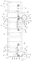
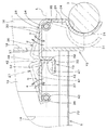
図1〜図8は本発明の第1実施形態を示している。図8において、建枠1の一対の横材3間に足場の踏み板5が架設されている。踏み板5の長手方向両端部にそれぞれ一対の係合体6が突設されており、これら係合体6を建枠1の一対の横材3に上側から係合させることにより、一対の横材3間に踏み板5が水平状に配置固定されている。
Hereinafter, embodiments of the present invention will be described with reference to the drawings.
1 to 8 show a first embodiment of the present invention. In FIG. 8, a footboard 5 of a scaffold is constructed between a pair of cross members 3 of the building frame 1. A pair of engaging bodies 6 are projected from both ends of the tread plate 5 in the longitudinal direction, and by engaging these engaging bodies 6 with the pair of cross members 3 of the building frame 1 from above, The tread plate 5 is horizontally arranged and fixed.

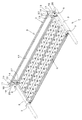
建枠1の一対の横材3間に、踏み板5の外側縁部に沿って幅木8が立設され、幅木8で踏み板5上の建築資材等が落下するのを防止している。
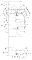
図1〜図8において、幅木8は、一対の横材3間に渡る長さの幅木本体9と、この幅木本体9の長手方向両端を横材3に取り付ける一対の装着手段10とを備えている。
幅木本体9は一対の横材3の離間方向に細長くて所定の上下幅を有する長方形の板部材13を有すると共に、板部材13の長手方向両端部に設けた一対の支持板14を有している。また、幅木本体9は長手方向端部に、建枠1の内外方向に離間した端部内壁16と端部外壁17とを有すると共に、端部内壁16と端部外壁17とを繋ぐ奥壁18とを有しており、端部内壁16と端部外壁17と奥壁18とで長手方向外方に開放された断面コ字状部材19が形成されている。板部材13の長手方向両端に断面コ字状部材19が奥壁18を介して溶接等により固着されている。
A skirting board 8 is erected between the pair of cross members 3 of the building frame 1 along the outer edge of the tread board 5, thereby preventing the building materials and the like on the tread board 5 from falling by the skirting board 8.
In FIG. 1 to FIG. 8, the skirting board 8 includes a baseboard body 9 having a length extending between a pair of crosspieces 3, and a pair of mounting means 10 for attaching both longitudinal ends of the baseboard body 9 to the crosspiece 3. It has.
The skirting board body 9 has a rectangular plate member 13 that is elongated in the separating direction of the pair of cross members 3 and has a predetermined vertical width, and has a pair of support plates 14 provided at both longitudinal ends of the plate member 13. ing. In addition, the baseboard body 9 has an end inner wall 16 and an end outer wall 17 that are spaced apart in the inner and outer directions of the building frame 1 at the end in the longitudinal direction, and a back wall that connects the end inner wall 16 and the end outer wall 17. A U-shaped cross-section member 19 that is open outward in the longitudinal direction is formed by the end inner wall 16, the end outer wall 17, and the back wall 18. A U-shaped cross-section member 19 is fixed to both ends in the longitudinal direction of the plate member 13 by welding or the like via the back wall 18.

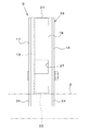
板部材13はその上端部に建枠1内外方向の内方に突出した後に下方に屈曲した上折曲縁部21を有すると共に、下端部に建枠1内外方向の内方に突出した後に上方に向けて屈曲した下折曲縁部22を有している。
一対の支持板14は、板部材13の建枠1内外方向の内方に上下方向に配置され、その上下両端部が板部材13の上折曲縁部21と下折曲縁部22とに連結固定されている。
The plate member 13 has an upper bent edge portion 21 that protrudes inward in the building frame 1 inward and outward at the upper end portion thereof, and upwards after protruding inward in the building frame 1 at the lower end portion. It has the downward bending edge part 22 bent toward the direction.
The pair of support plates 14 are arranged in the vertical direction inside and outside the building frame 1 of the plate member 13, and both upper and lower ends thereof are connected to the upper bent edge 21 and the lower bent edge 22 of the plate member 13. Connected and fixed.

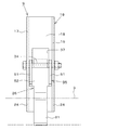
断面コ字状部材19の端部内壁16と端部外壁17との下部に、載置嵌合部24が設けられている。載置嵌合部24は端部内壁16と端部外壁17との下部における幅木本体長手方向の外方側を円弧状に切り欠いてなり、横材3に嵌合して幅木本体9の長手方向外方及び下方への移動を規制する。載置嵌合部24が横材3に嵌合することによって、幅木本体9がその下部を支点に建枠1内外方向に揺動しないように横材3に対して端部内壁16側と端部外壁17側の2点で安定に嵌合保持できるように構成されている。   A placement fitting portion 24 is provided below the end inner wall 16 and the end outer wall 17 of the U-shaped member 19. The mounting fitting portion 24 is formed by cutting out the outer side in the longitudinal direction of the baseboard body at the lower part of the end inner wall 16 and the end outer wall 17 in an arc shape, and is fitted to the cross member 3 to fit the baseboard body 9. The movement in the longitudinal direction outward and downward is regulated. When the mounting fitting portion 24 is fitted to the cross member 3, the end wall inner wall 16 side with respect to the cross member 3 is prevented so that the baseboard body 9 does not swing inward and outward of the building frame 1 with the lower part as a fulcrum. It is configured so that it can be stably fitted and held at two points on the end outer wall 17 side.

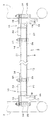
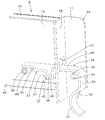
前記各装着手段10は、横材3に係脱自在に係合する係合部材26と、係合部材26を横材3に係合した状態にロックするロック部材27とを有する。
係合部材26は横軸34に回動自在に嵌合する円筒状の軸受部35に第1翼29と第2翼30とが突出され、第1翼29に円弧状に湾曲しかつ建枠1の内外方向に一定の幅を有する係合部31が形成され、第2翼30にロック部材27と当接する当接部32がL字状に屈曲形成されている。
Each mounting means 10 includes an engaging member 26 that is detachably engaged with the cross member 3, and a lock member 27 that locks the engaging member 26 in a state of being engaged with the cross member 3.
The engaging member 26 has a first wing 29 and a second wing 30 projecting from a cylindrical bearing portion 35 that is rotatably fitted to a horizontal shaft 34, and is curved in an arc shape on the first wing 29. An engagement portion 31 having a certain width is formed in the inner and outer directions of the first member, and a contact portion 32 that contacts the lock member 27 is bent and formed in an L shape on the second blade 30.

横軸34は載置嵌合部24の上方に配置され、断面コ字状部材19の端部内壁16と端部外壁17との間に架設されている。係合部材26は断面コ字状部材19の端部内壁16と端部外壁17との間に配置されて、幅木本体9の長手方向端部に横軸34を介して揺動自在に支持され、揺動して係合部31が横材3に係脱自在に係合し、係合部31が横材3に係合することにより、幅木本体9の長手方向外方及び上方への移動を規制するようになっている。   The horizontal shaft 34 is disposed above the placement fitting portion 24 and is laid between the end inner wall 16 and the end outer wall 17 of the U-shaped cross-section member 19. The engaging member 26 is disposed between the end inner wall 16 and the end outer wall 17 of the U-shaped member 19 in cross section, and is supported at the longitudinal end of the baseboard body 9 through a horizontal shaft 34 so as to be swingable. By swinging, the engaging portion 31 is detachably engaged with the cross member 3, and the engaging portion 31 is engaged with the cross member 3. Is supposed to regulate movement.

前記係合部材26の第2翼30の当接部32側は奥壁18に設けた開口孔37から板部材13の建枠1内外方向の内側に突出されている。
ロック部材27は支持軸39を介して揺動自在に支持されている。支持軸39は、横軸34の幅木長手方向の内方側に配置され、幅木本体9の板部材13と支持板14と間に架設されている。支持軸39に円筒状の軸受部40が回動自在に嵌合され、ロック部材27は軸受部40からL字状に突設され、幅木本体9の断面コ字状部材19よりも長手方向の内方側に配置されている。ロック部材27の先端に下方に屈曲したロック部42が形成されている。
The contact portion 32 side of the second wing 30 of the engagement member 26 protrudes from the opening hole 37 provided in the inner wall 18 to the inside of the plate member 13 in the building frame 1 inside / outside direction.
The lock member 27 is swingably supported via a support shaft 39. The support shaft 39 is disposed on the inner side of the horizontal shaft 34 in the longitudinal direction of the skirting board, and is laid between the plate member 13 and the support plate 14 of the skirting board main body 9. A cylindrical bearing 40 is rotatably fitted to the support shaft 39, and the lock member 27 protrudes in an L shape from the bearing 40, and is longer in the longitudinal direction than the U-shaped member 19 in the cross section of the baseboard body 9. It is arranged on the inner side. A lock portion 42 that is bent downward is formed at the tip of the lock member 27.

また、ロック部材27には幅木本体9の側面から建枠1内外方向に突出した摘み部44が設けられている。摘み部44は幅木本体9の支持板14よりも長手方向外方に配置され、支持板14よりも建枠1内外方向の内方に突出しており、摘み部44を摘んでロック部材27を揺動操作できるようになっている。
前記係合部材26の当接部32は下方に屈曲した後に幅木長手方向の内方側に屈曲することにより上述の如くL字状に屈曲しており、当接部32には、ロック部材27のロック部42が当接して揺動力を受ける受け面47と、揺動したときに横軸34と支持軸39とを通る中心線Lに対して略直交してロック部42と面接する被ロック面48とが形成されている。
The lock member 27 is provided with a knob 44 that protrudes inward and outward from the side surface of the skirting board main body 9. The knob 44 is disposed outward in the longitudinal direction from the support plate 14 of the skirting board body 9 and protrudes inward of the building frame 1 from the support plate 14. It can be swung.
The abutting portion 32 of the engaging member 26 is bent downward and then bent inward in the baseboard longitudinal direction to be bent in an L shape as described above. 27, a receiving surface 47 that receives the rocking force by abutting the lock portion 42, and a surface to be in contact with the lock portion 42 substantially perpendicularly to a center line L passing through the horizontal shaft 34 and the support shaft 39 when the rocking portion 42 is swung. A lock surface 48 is formed.

而して、係合部材26及びロック部材27が、図5に2点鎖線で示す如く互いに山形状に屈曲傾斜して、係合部材26の係合部31が横材3から外れた状態から、ロック部材27を支持軸39廻りに図5に示す矢印a方向に揺動させると、ロック部材27のロック部42が係合部材26の当接部32(受け面47)に当接して下方に押圧し、これに伴い、係合部材26が横軸34廻りに図5に示す矢印c方向に揺動してその係合部31が横材3に係合し、このとき、ロック部材27のロック部42が係合部材26の当接部32(被ロック面48)と面接触し、これによりロック部材27と係合部材26とが互いに突っ張り状態になり、ロック部材27で係合部材26を横材3に係合した状態にロックするように構成されている。   Thus, the engagement member 26 and the lock member 27 are bent and inclined in a mountain shape as shown by a two-dot chain line in FIG. 5, and the engagement portion 31 of the engagement member 26 is detached from the cross member 3. When the lock member 27 is swung around the support shaft 39 in the direction of arrow a shown in FIG. 5, the lock portion 42 of the lock member 27 comes into contact with the contact portion 32 (receiving surface 47) of the engagement member 26 and moves downward. Accordingly, the engaging member 26 swings in the direction of the arrow c shown in FIG. 5 around the horizontal shaft 34 and the engaging portion 31 engages with the horizontal member 3. At this time, the locking member 27 The locking portion 42 of the engaging member 26 comes into surface contact with the abutting portion 32 (locked surface 48) of the engaging member 26, so that the locking member 27 and the engaging member 26 are stretched to each other. 26 is configured to be locked in a state of being engaged with the cross member 3.

上記第1実施形態によれば、幅木8を一対の横材3間に取り付ける場合、図1及び図5に2点鎖線で示す如く、ロック部材27を支持軸39廻りに図5に示す矢印b方向に揺動してロックを解除すると共に、係合部材26を横軸34廻りに図5に示す矢印d方向に揺動して、ロック部材27と係合部材26とを山形状に屈曲傾斜させておき、この状態で、図7(a)に示すように幅木8を一対の横材3よりもやや高く持ち上げた後に、幅木8を降ろして、図7(b)に示すように幅木本体9の長手方向両端部の載置嵌合部24をそれぞれ一対の横材3に嵌合する。これによって、幅木8を一対の横材3に対して位置決めすることができると共に、幅木8の重量を一対の横材3に預けることができる。   According to the first embodiment, when the skirting board 8 is attached between the pair of cross members 3, as shown by the two-dot chain line in FIG. 1 and FIG. The lock member 27 is swung in the direction b to release the lock, and the engaging member 26 is swung around the horizontal axis 34 in the direction of the arrow d shown in FIG. 5 to bend the lock member 27 and the engaging member 26 in a mountain shape. In this state, after the baseboard 8 is lifted slightly higher than the pair of cross members 3 as shown in FIG. 7 (a), the baseboard 8 is lowered and as shown in FIG. 7 (b). The mounting fitting portions 24 at both ends in the longitudinal direction of the skirting board main body 9 are fitted into the pair of cross members 3 respectively. Accordingly, the skirting board 8 can be positioned with respect to the pair of cross members 3, and the weight of the skirting board 8 can be deposited in the pair of cross members 3.

その後、ロック部材27の摘み部44を摘んでロック部材27を下方に押圧して、ロック部材27を図5に示す矢印a方向に揺動操作すればよく、ロック部材27のロック部42が当接部32の受け面47に当接して、ロック部材27の矢印a方向への揺動に伴って、当接部32を下方に押圧し、その結果、係合部材26を図5に示す矢印c方向に揺動させ、図7(C)に示すように係合部材26の係合部31が横材3に幅木本体9の長手方向の内側から係脱自在に係合する。   Thereafter, the knob 44 of the lock member 27 is picked, the lock member 27 is pressed downward, and the lock member 27 is swung in the direction of arrow a shown in FIG. Abutting on the receiving surface 47 of the contact portion 32 and pressing the contact portion 32 downward as the lock member 27 swings in the direction of arrow a. As a result, the engagement member 26 is moved to the arrow shown in FIG. As shown in FIG. 7C, the engaging portion 31 of the engaging member 26 is detachably engaged with the cross member 3 from the inner side in the longitudinal direction of the skirting board main body 9 as shown in FIG.

このとき、ロック部材27のロック部42が係合部材26の被ロック面48と面接触して、ロック部材27と係合部材26とが突っ張り状態になり、ロック部材27によって係合部材26が横材3に係合した状態にロックされる。
従って、幅木8を一対の横材3に取り付ける場合に、端部内壁16及び端部外壁17の下部に設けた載置嵌合部24を、一対の横材3に嵌合することによって、幅木8を一対の横材3に対して位置決めすることができると共に、幅木8を一対の横材3に立ち姿勢で預けることができるため、その後に、一対の装着手段10の係合部材26をそれぞれ横材3に簡単に係合させて、幅木8を一対の横材3間に簡単かつ確実に取り付けることができる。また、装着手段10の係合部材26をそれぞれ横材3に係合した後も、端部内壁16及び端部外壁17の下部に設けた載置嵌合部24は一対の横材3に嵌合したままになっており、幅木8を一対の横材3間に確実かつ安定に取り付けておくことができる。
At this time, the lock portion 42 of the lock member 27 comes into surface contact with the locked surface 48 of the engagement member 26, and the lock member 27 and the engagement member 26 are stretched. It is locked in a state engaged with the cross member 3.
Therefore, when the baseboard 8 is attached to the pair of cross members 3, by fitting the placement fitting portion 24 provided at the lower part of the end inner wall 16 and the end outer wall 17 to the pair of cross members 3, Since the skirting board 8 can be positioned with respect to the pair of cross members 3 and the skirting board 8 can be deposited in a standing posture on the pair of cross members 3, thereafter, the engaging members of the pair of mounting means 10 The base plates 8 can be easily and reliably attached between the pair of cross members 3 by easily engaging the cross members 26 with the cross members 3. Further, even after the engaging members 26 of the mounting means 10 are engaged with the cross members 3, the mounting fitting portions 24 provided at the lower portions of the end inner wall 16 and the end outer wall 17 are fitted to the pair of cross members 3. The baseboard 8 can be securely and stably attached between the pair of cross members 3.

しかも、断面コ字状部材19の端部内壁16と端部外壁17との下部に載置嵌合部24が設けられ、係合部材26は断面コ字状部材19の端部内壁16と端部外壁17との間に配置されているので、載置嵌合部24が横材3に嵌合されると共に、係合部材26が建枠1の内外方向に一定の幅を有する係合部31で横材3に係合されることによって、幅木本体9がその下部を支点に建枠1内外方向に揺動しないように横材3に対して端部内壁16側と端部外壁17側の2点で安定に嵌合保持できるし、係合部31の建枠1内外方向の幅によっても建枠1内外方向にガタ付かないように保持することができ、幅木8を一対の横材3に建枠1の内外方向に倒れないように安定かつ強固に固定することができる。   Moreover, a mounting fitting portion 24 is provided below the end inner wall 16 and the end outer wall 17 of the U-shaped cross-section member 19, and the engaging member 26 is connected to the end inner wall 16 and the end of the U-shaped cross-section 19. Since the mounting fitting portion 24 is fitted to the cross member 3 and the engaging member 26 has a certain width in the inner and outer direction of the building frame 1 because it is disposed between the outer wall 17 and the outer wall 17. By engaging with the cross member 3 at 31, the end inner wall 16 side and the end outer wall 17 with respect to the cross member 3 are prevented so that the baseboard body 9 does not swing in the direction of the building frame 1 with the lower part as a fulcrum. It can be stably fitted and held at two points on the side, and can be held so that it does not rattle in or out of the building frame 1 depending on the width of the engaging portion 31 in the inside or outside of the building frame 1. It can be stably and firmly fixed to the cross member 3 so as not to fall in the inner and outer directions of the building frame 1.

また、幅木本体9の長手方向両端を横材3に取り付ける一対の装着手段10は、横材3に係脱自在に係合する係合部材26と、係合部材26を横材3に係合した状態にロックするロック部材27とを有する簡単な構成であって、幅木本体9の長手方向両端部の下部側にコンパクトに配置することができ、構成が簡単で構成部材が少なくて済み、幅木8全体を安価でかつ安上がりに製造することができる。   The pair of mounting means 10 for attaching both ends of the baseboard body 9 in the longitudinal direction to the cross member 3 includes an engagement member 26 that is detachably engaged with the cross member 3, and the engagement member 26 is engaged with the cross member 3. It has a simple configuration having a lock member 27 that locks in the combined state, and can be disposed compactly at the lower side of both longitudinal ends of the skirting board main body 9, and the configuration is simple and the number of configuration members can be reduced. The whole skirting board 8 can be manufactured at low cost and at low cost.

なお、幅木8を一対の横材3間から取り外す場合には、ロック部材27の摘み部44を摘んでロック部材27を上方に引っ張り上げて、ロック部材27を矢印b方向に揺動操作すればよく、ロック部材27の矢印b方向への揺動に伴って、ロック部42が当接部32に接触して上方に引っ張り上げ、その結果、係合部材26を矢印d方向に揺動させ、係合部材26の係合部31が横材3から幅木本体9の長手方向の内側に離間し、係合部材26の横材3への係合が外れる。従って、その後は、幅木8を一対の横材3よりもやや高く持ち上げて、幅木本体9の長手方向両端部の載置嵌合部24をそれぞれ一対の横材3から外せばよい。   When the skirting board 8 is removed from between the pair of cross members 3, the knob 44 of the lock member 27 is picked and the lock member 27 is pulled upward, and the lock member 27 is swung in the direction of arrow b. As the lock member 27 swings in the direction of arrow b, the lock portion 42 comes into contact with the contact portion 32 and pulls upward. As a result, the engagement member 26 swings in the direction of arrow d. The engaging portion 31 of the engaging member 26 is separated from the cross member 3 inward in the longitudinal direction of the skirting board main body 9, and the engagement of the engaging member 26 with the cross member 3 is released. Therefore, after that, the skirting board 8 may be lifted slightly higher than the pair of cross members 3, and the placement fitting portions 24 at both ends in the longitudinal direction of the base board body 9 may be removed from the pair of cross members 3.

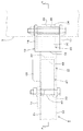
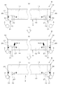
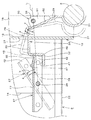
図9〜図13は本発明の第2実施形態を示している。図9〜図13において、前記装着手段10の一方(図例では左側の装着手段10)は、係合部31を有する係合部材26が幅木本体9の長手方向端部に固定されている。
即ち、横軸34に嵌合する軸受部35は、建枠1の内外方向に離間した一対の軸受片51と軸受片51を連結する連結片52とをコの字状に有し、一対の軸受片51が取付孔を介して横軸34に嵌合されると共に、端部内壁16の内面又は端部外壁17の内面に沿うように配置されて、軸受部35が断面コ字状部材19に内嵌されている。
9 to 13 show a second embodiment of the present invention. 9 to 13, one of the mounting means 10 (the left mounting means 10 in the illustrated example) has an engaging member 26 having an engaging portion 31 fixed to the longitudinal end of the baseboard body 9. .
That is, the bearing part 35 fitted to the horizontal shaft 34 has a pair of bearing pieces 51 spaced in the inner and outer directions of the building frame 1 and a connecting piece 52 for connecting the bearing pieces 51 in a U-shape, The bearing piece 51 is fitted to the horizontal shaft 34 through the mounting hole, and is disposed along the inner surface of the end inner wall 16 or the inner surface of the end outer wall 17, so that the bearing portion 35 has a U-shaped cross-section member 19. It is fitted inside.

また、係合部材26に断面コ字状部材19の奥壁18に接当する接当片54が突設され、これにより、係合部材26が断面コ字状部材19に対して動かないように固定されている。
前記装着手段10の他方(図例では右側の装着手段10)は、前記第1実施形態の場合と同様に、幅木本体9の長手方向端部に横軸34を介して揺動自在に支持されかつ揺動して横材3に係脱自在に係合する係合部31を有する係合部材26と、この係合部材26を揺動した状態でロックするロック部材27とを有している。
In addition, a contact piece 54 that contacts the back wall 18 of the U-shaped cross-section member 19 protrudes from the engagement member 26, so that the engagement member 26 does not move relative to the U-shaped cross-section member 19. It is fixed to.
The other of the mounting means 10 (right mounting means 10 in the figure) is swingably supported at the longitudinal end of the skirting board main body 9 via a horizontal shaft 34 as in the case of the first embodiment. And an engaging member 26 having an engaging portion 31 that swings and engages and disengages with the cross member 3 and a lock member 27 that locks the engaging member 26 in a swinging state. Yes.

他方の装着手段10の横軸34に嵌合する軸受部35は、左側の装着手段10の場合と同様に、前後一対の軸受片51と軸受片51を連結する連結片52とをコの字状に有し、一対の軸受片51が取付孔を介して横軸34に嵌合されると共に、端部内壁16の内面又は端部外壁17の内面に沿うように配置されて、軸受部35が断面コ字状部材19に内嵌されている。   As in the case of the left mounting means 10, the bearing portion 35 fitted to the horizontal shaft 34 of the other mounting means 10 includes a pair of front and rear bearing pieces 51 and a connecting piece 52 that connects the bearing pieces 51. The pair of bearing pieces 51 are fitted to the horizontal shaft 34 through the mounting holes, and are arranged along the inner surface of the end inner wall 16 or the inner surface of the end outer wall 17, and the bearing portion 35. Is fitted into the U-shaped member 19 in cross section.

また、ロック部材27は、上壁部57と上壁部57の建枠1内外方向の両端から下方に突出した一対の側壁部58とを有するコの字状に形成され、ロック部材27の幅木本体9長手方向の中央部が支持軸39を介して揺動自在に支持されている。支持軸に39に一対の側壁部58が取付孔を介して回動自在に嵌合され、ロック部材27の幅木本体9長手方向の外端部がロック部42とされている。   In addition, the lock member 27 is formed in a U shape having an upper wall portion 57 and a pair of side wall portions 58 projecting downward from both ends of the upper wall portion 57 in the building frame 1 inside and outside. A central portion of the wood body 9 in the longitudinal direction is supported through a support shaft 39 so as to be swingable. A pair of side wall portions 58 is rotatably fitted to the support shaft 39 through an attachment hole, and an outer end portion of the lock member 27 in the longitudinal direction of the baseboard body 9 is a lock portion 42.

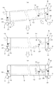
前記第1実施形態の場合と同様に、係合部材26の当接部32には、ロック部材27のロック部42が当接して揺動力を受ける受け面47と、揺動したときに横軸34と支持軸39とを通る中心線Lに対して略直交してロック部42と面接する被ロック面48とが形成されている。
而して、右側の装着手段10では、係合部材26及びロック部材27が、図12に2点鎖線で示す如く互いに山形状に屈曲傾斜して、係合部材26の係合部31が横材3から外れた状態から、ロック部材27を支持軸39廻りに図12に示す矢印a方向に揺動させると、ロック部材27のロック部42が係合部材26の当接部32(受け面47)に当接して下方に押圧し、これに伴い、係合部材26が横軸34廻りに図12に示す矢印c方向に揺動してその係合部31が横材3に係合し、このとき、ロック部材27のロック部42が係合部材26の当接部32(被ロック面48)と面接触し、これによりロック部材27と係合部材26とが互いに突っ張り状態になり、ロック部材27で係合部材26を横材3に係合した状態にロックするように構成されている。
As in the case of the first embodiment, the contact portion 32 of the engagement member 26 is in contact with the receiving surface 47 that receives the rocking force by the lock portion 42 of the lock member 27 coming into contact, and the horizontal axis when swung. A locked surface 48 that is in contact with the lock portion 42 is formed so as to be substantially perpendicular to the center line L passing through the support shaft 39 and the support shaft 39.
Thus, in the right mounting means 10, the engaging member 26 and the locking member 27 are bent and inclined in a mountain shape as shown by a two-dot chain line in FIG. When the lock member 27 is swung around the support shaft 39 in the direction of arrow a shown in FIG. 12 from the state where it is detached from the material 3, the lock portion 42 of the lock member 27 is brought into contact with the contact portion 32 (receiving surface) of the engagement member 26. 47) and pressed downward, and accordingly, the engaging member 26 swings around the horizontal shaft 34 in the direction of the arrow c shown in FIG. At this time, the lock portion 42 of the lock member 27 comes into surface contact with the abutting portion 32 (locked surface 48) of the engagement member 26, whereby the lock member 27 and the engagement member 26 are stretched to each other. The locking member 27 is used to lock the engaging member 26 in the engaged state with the cross member 3. It is configured.

上記第2実施形態によれば、幅木8を一対の横材3間に取り付ける場合、図12に2点鎖線で示す如く、ロック部材27を支持軸39廻りに図12に示す矢印b方向に揺動してロックを解除すると共に、右側の係合部材26を横軸34廻りに図12に示す矢印d方向に揺動して、ロック部材27と係合部材26とを山形状に屈曲傾斜させておき、この状態で、幅木8を一対の横材3よりもやや高く持ち上げた後に、図13(a)に示すように、幅木8の左側を降ろして、幅木本体9の左側の載置嵌合部24を横材3に嵌合する。これによって、幅木8を横材3に対して長手方向に位置決めすることができると共に、幅木8の重量の左側を横材3に預けることができる。   According to the second embodiment, when the skirting board 8 is attached between the pair of cross members 3, the lock member 27 is moved around the support shaft 39 in the direction of the arrow b shown in FIG. The lock member 27 is rocked to release the lock, and the right engagement member 26 is swung around the horizontal axis 34 in the direction of the arrow d shown in FIG. 12, so that the lock member 27 and the engagement member 26 are bent and inclined in a mountain shape. In this state, after the skirting board 8 is lifted slightly higher than the pair of cross members 3, the left side of the skirting board 8 is lowered as shown in FIG. The mounting fitting portion 24 is fitted to the cross member 3. As a result, the skirting board 8 can be positioned in the longitudinal direction with respect to the crosspiece 3 and the left side of the weight of the skirting board 8 can be deposited in the crosspiece 3.

次に、幅木8の右側を降ろして、図13(b)に示すように幅木本体9の右側の載置嵌合部24を横材3に嵌合する。これによって、幅木8を一対の横材3に対して位置決めすることができると共に、幅木8の重量を一対の横材3に預けることができる。
その後、ロック部材27の右側を下方に押して、ロック部材27を図12に示す矢印a方向に揺動操作すればよく、ロック部材27のロック部42が当接部32の受け面47に当接して、ロック部材27の矢印a方向への揺動に伴って、当接部32を下方に押圧し、その結果、係合部材26を図12に示す矢印c方向に揺動させ、図13(C)に示すように右側の係合部材26の係合部31が横材3に幅木本体9の長手方向の内側から係脱自在に係合する。
Next, the right side of the skirting board 8 is lowered, and the placement fitting portion 24 on the right side of the skirting board main body 9 is fitted to the cross member 3 as shown in FIG. Accordingly, the skirting board 8 can be positioned with respect to the pair of cross members 3, and the weight of the skirting board 8 can be deposited in the pair of cross members 3.
Thereafter, the right side of the lock member 27 is pushed downward to swing the lock member 27 in the direction of arrow a shown in FIG. 12, and the lock portion 42 of the lock member 27 contacts the receiving surface 47 of the contact portion 32. As the lock member 27 swings in the direction of arrow a, the contact portion 32 is pressed downward, and as a result, the engaging member 26 swings in the direction of arrow c shown in FIG. As shown in C), the engaging portion 31 of the right engaging member 26 engages with the cross member 3 so as to be freely disengaged from the inside in the longitudinal direction of the baseboard body 9.

このとき、ロック部材27のロック部42が係合部材26の被ロック面48と面接触して、ロック部材27と係合部材26とが突っ張り状態になり、ロック部材27によって係合部材26が横材3に係合した状態にロックされる。
従って、前記第1実施形態の場合と同様に、幅木8を一対の横材3に建枠1の内外方向に倒れないように安定かつ強固に固定することができる。
At this time, the lock portion 42 of the lock member 27 comes into surface contact with the locked surface 48 of the engagement member 26, and the lock member 27 and the engagement member 26 are stretched. It is locked in a state engaged with the cross member 3.
Therefore, as in the case of the first embodiment, the skirting board 8 can be stably and firmly fixed to the pair of cross members 3 so as not to fall inward and outward of the building frame 1.

また、幅木本体9の長手方向両端を横材3に取り付ける一対の装着手段10は、横材3に係脱自在に係合する係合部材26を有する簡単な構成であって、幅木本体9の長手方向両端部の下部側にコンパクトに配置することができ、構成が簡単で構成部材が少なくて済み、幅木8全体を安価でかつ安上がりに製造することができる。
なお、幅木8を一対の横材3間から取り外す場合には、図13(C)に2点鎖線で示す如くロック部材27の左側を下方に押圧して、ロック部材27を矢印b方向に揺動操作すればよく、ロック部材27の矢印b方向への揺動に伴って、ロック部42が当接部32に接触して上方に引っ張り上げ、その結果、右側の係合部材26を矢印d方向に揺動させ、係合部材26の係合部31が横材3から幅木本体9の長手方向の内側に離間し、係合部材26の横材3への係合が外れる。従って、その後は、幅木8の右側を横材3よりもやや高く持ち上げて、幅木本体9の長手方向右端部の載置嵌合部24を横材3から外せばよい。
The pair of mounting means 10 for attaching both ends in the longitudinal direction of the skirting board main body 9 to the cross member 3 is a simple structure having an engaging member 26 detachably engaged with the cross member 3, 9 can be disposed compactly on the lower side of both ends in the longitudinal direction, the configuration is simple and the number of constituent members can be reduced, and the entire skirting board 8 can be manufactured inexpensively and inexpensively.
When removing the skirting board 8 between the pair of cross members 3, press the left side of the lock member 27 downward as shown by a two-dot chain line in FIG. As the lock member 27 swings in the direction of the arrow b, the lock portion 42 comes into contact with the contact portion 32 and is pulled upward. As a result, the right engagement member 26 is moved to the arrow. By swinging in the d direction, the engaging portion 31 of the engaging member 26 is separated from the cross member 3 inward in the longitudinal direction of the skirting board main body 9, and the engagement member 26 is disengaged from the cross member 3. Therefore, after that, the right side of the skirting board 8 may be lifted slightly higher than the cross member 3, and the placement fitting portion 24 at the right end in the longitudinal direction of the base board body 9 may be removed from the cross member 3.

なお、前記実施形態では、幅木本体9の長手方向両端を横材3に取り付ける一対の又は一方の装着手段10は、横材3に係脱自在に係合して幅木本体9の長手方向外方及び上方への移動を規制する係合部材26を有する他に、係合部材26を揺動した状態でロックするロック部材27を有しているが、ロック部材27に代えて、係合部材26を揺動した状態に固定するボルトナット等の締結具を設けてもよい。   In the embodiment, the pair or one mounting means 10 for attaching both ends in the longitudinal direction of the baseboard body 9 to the cross member 3 is detachably engaged with the cross member 3 and the longitudinal direction of the base plate body 9 is engaged. In addition to the engagement member 26 that restricts outward and upward movement, the lock member 27 has a lock member 27 that locks the engagement member 26 in a rocked state. You may provide fasteners, such as a bolt nut which fixes the member 26 in the rock | fluctuated state.

1 建枠
3 横材
5 踏み板
6 係合体
8 幅木
9 幅木本体
10 装着手段
16 端部内壁
17 端部外壁
18 奥壁
19 断面コ字状部材
24 載置嵌合部
26 係合部材
27 ロック部材
29 第1翼
30 第2翼
32 当接部
34 横軸
35 軸受部
39 支持軸
42 ロック部
47 受け面
48 被ロック面
L 中心線
DESCRIPTION OF SYMBOLS 1 Building frame 3 Cross member 5 Footboard 6 Engagement body 8 Skirting board 9 Skirting board main body 10 Mounting means 16 End part inner wall 17 End part outer wall 18 Back wall 19 Cross-section U-shaped member 24 Mounting fitting part 26 Engaging member 27 Lock Member 29 First blade 30 Second blade 32 Contact portion 34 Horizontal shaft 35 Bearing portion 39 Support shaft 42 Lock portion 47 Receiving surface 48 Locked surface L Center line

Claims (6)

踏み板(5)を架設する建枠(1)の一対の横材(3)間に渡る長さの幅木本体(9)と、この幅木本体(9)の長手方向両端を横材(3)に取り付ける一対の装着手段(10)とを備えており、前記各装着手段(10)は横材(3)に係脱自在に係合して幅木本体(9)の長手方向外方及び上方への移動を規制する係合部材(26)を有する幅木であって、
前記幅木本体(9)は長手方向端部に、建枠(1)内外方向に離間していてその間に係合部材(26)を配置した端部内外壁(16,17)を有し、この端部内外壁(16,17)の下部に、横材(3)に嵌合して幅木本体(9)の長手方向外方及び下方への移動を規制する載置嵌合部(24)を設けていることを特徴とする幅木。
A skirting board main body (9) having a length extending between a pair of cross members (3) of the building frame (1) on which the tread board (5) is installed, and both ends in the longitudinal direction of the skirting board main body (9) are cross members (3 And a pair of attachment means (10) attached to each other, and each of the attachment means (10) is detachably engaged with the cross member (3) to disengage the baseboard body (9) in the longitudinal direction and A baseboard having an engagement member (26) for restricting upward movement,
The baseboard body (9) has end inner and outer walls (16, 17) which are spaced apart from each other in the building frame (1) in the longitudinal direction and the engaging members (26) are disposed therebetween at the longitudinal ends. On the lower part of the inner wall of the end portion (16, 17), there is a mounting fitting portion (24) which is fitted to the cross member (3) and regulates the movement of the baseboard body (9) in the longitudinal direction outward and downward. A skirting board characterized by providing.
前記幅木本体(9)は長手方向端部に、端部内外壁(16,17)とそれらを繋ぐ奥壁(18)とを有して長手方向外方に開放された断面コ字状部材(19)を有し、この断面コ字状部材(19)の下端に前記載置嵌合部(24)を形成していることを特徴とする請求項1に記載の幅木。   The said base board main body (9) has a cross-section U-shaped member which has the inner wall (16,17) of an edge part and the back wall (18) which connects them in the longitudinal direction edge part, and was open | released longitudinally outward ( The baseboard according to claim 1, wherein the base fitting portion (24) is formed at a lower end of the U-shaped member (19). 前記装着手段(10)の一方は、前記係合部材(26)が幅木本体(9)の長手方向端部に固定され、他方は、幅木本体(9)の長手方向端部に横軸(34)を介して揺動自在に支持されかつ揺動して横材(3)に係脱自在に係合する係合部(31)を有する前記係合部材(26)と、この係合部材(26)を揺動した状態でロックするロック部材(27)とを有することを特徴とする請求項1又は2に記載の幅木。   One of the mounting means (10) has the engaging member (26) fixed to the longitudinal end of the baseboard body (9), and the other is the horizontal axis at the longitudinal end of the baseboard body (9). The engagement member (26) having an engagement portion (31) supported so as to be swingable through (34) and swingably engaged with and disengaged from the cross member (3). The baseboard according to claim 1 or 2, further comprising a lock member (27) that locks the member (26) in a swinging state. 前記両方の装着手段(10)は、幅木本体(9)の長手方向端部に横軸(34)を介して揺動自在に支持されかつ揺動して横材(3)に係脱自在に係合する係合部(31)を有する前記係合部材(26)と、この係合部材(26)を揺動した状態でロックするロック部材(27)とを有することを特徴とする請求項1又は2に記載の幅木。   Both the mounting means (10) are swingably supported at the longitudinal end of the baseboard body (9) via the horizontal shaft (34) and swingable to and from the horizontal member (3). The engagement member (26) having an engagement portion (31) engaged with the lock member, and a lock member (27) for locking the engagement member (26) in a swinging state. Item 3. A baseboard according to item 1 or 2. 前記揺動自在に支持された係合部材(26)は横軸(34)に嵌合する軸受部(35)に第1翼(29)と第2翼(30)とを突出し、第1翼(29)に前記係合部(31)を形成し、第2翼(30)にロック部材(27)と当接する当接部(32)を形成しており、
前記ロック部材(27)は支持軸(39)を介して揺動自在に支持され、その先端に揺動して係合部材(26)の当接部(32)と面接触して互いに突っ張り状態になるロック部(42)を形成していることを特徴とする請求項3又は4に記載の幅木。
The swingingly supported engaging member (26) projects the first blade (29) and the second blade (30) from the bearing portion (35) fitted to the horizontal shaft (34), and the first blade. The engagement portion (31) is formed in (29), and the contact portion (32) that contacts the lock member (27) is formed in the second wing (30),
The lock member (27) is swingably supported via a support shaft (39), swings at the tip of the lock member (27), and comes into surface contact with the abutting portion (32) of the engagement member (26) so as to be in tension with each other. The baseboard according to claim 3 or 4, wherein a lock portion (42) is formed.
前記係合部材(26)の当接部(32)には、ロック部材(27)のロック部(42)が当接して揺動力を受ける受け面(47)と、揺動したときに横軸(34)と支持軸(39)とを通る中心線(L)に対して略直交してロック部(42)と面接する被ロック面(48)とを形成していることを特徴とする請求項5に記載の幅木。   The abutting portion (32) of the engaging member (26) is contacted by the locking portion (42) of the locking member (27) and receives a swinging force. A locked surface (48) that is in contact with the lock portion (42) is formed substantially orthogonal to a center line (L) passing through (34) and the support shaft (39). Item 6. A skirting board according to item 5.
JP2012183403A 2012-08-22 2012-08-22 Baseboard Pending JP2014040734A (en)

Priority Applications (1)

Application Number Priority Date Filing Date Title
JP2012183403A JP2014040734A (en) 2012-08-22 2012-08-22 Baseboard

Applications Claiming Priority (1)

Application Number Priority Date Filing Date Title
JP2012183403A JP2014040734A (en) 2012-08-22 2012-08-22 Baseboard

Publications (1)

Publication Number Publication Date
JP2014040734A true JP2014040734A (en) 2014-03-06

Family

ID=50393179

Family Applications (1)

Application Number Title Priority Date Filing Date
JP2012183403A Pending JP2014040734A (en) 2012-08-22 2012-08-22 Baseboard

Country Status (1)

Country Link
JP (1) JP2014040734A (en)

Citations (8)

* Cited by examiner, † Cited by third party
Publication number Priority date Publication date Assignee Title
JPS5112774B2 (en) * 1972-06-19 1976-04-22
JP2003129655A (en) * 2001-10-25 2003-05-08 Kamatetsu Kizai Co Ltd Baseboard for framework scaffold
JP2004011155A (en) * 2002-06-04 2004-01-15 Alinco Inc Scaffolding board
JP2004360268A (en) * 2003-06-04 2004-12-24 Alinco Inc Scaffolding board
JP2006169902A (en) * 2004-12-20 2006-06-29 Kyc Machine Industry Co Ltd Temporary scaffolding skirting boards
JP2011042946A (en) * 2009-08-20 2011-03-03 Shinwa Kk Baseboard for scaffold
JP2011149194A (en) * 2010-01-21 2011-08-04 Daisan:Kk Baseboard for temporary scaffold
CN102168486A (en) * 2011-03-28 2011-08-31 张连元 Door-type steel pipe scaffold fastener and self-locking anti-drop device

Patent Citations (8)

* Cited by examiner, † Cited by third party
Publication number Priority date Publication date Assignee Title
JPS5112774B2 (en) * 1972-06-19 1976-04-22
JP2003129655A (en) * 2001-10-25 2003-05-08 Kamatetsu Kizai Co Ltd Baseboard for framework scaffold
JP2004011155A (en) * 2002-06-04 2004-01-15 Alinco Inc Scaffolding board
JP2004360268A (en) * 2003-06-04 2004-12-24 Alinco Inc Scaffolding board
JP2006169902A (en) * 2004-12-20 2006-06-29 Kyc Machine Industry Co Ltd Temporary scaffolding skirting boards
JP2011042946A (en) * 2009-08-20 2011-03-03 Shinwa Kk Baseboard for scaffold
JP2011149194A (en) * 2010-01-21 2011-08-04 Daisan:Kk Baseboard for temporary scaffold
CN102168486A (en) * 2011-03-28 2011-08-31 张连元 Door-type steel pipe scaffold fastener and self-locking anti-drop device

Similar Documents

Publication Publication Date Title
JP2009221786A (en) Connecting structure of scaffold member in temporary scaffold
JP5178286B2 (en) Cable bracket
JP2012197609A (en) Precedence balustrade
JP5270147B2 (en) Temporary scaffolding connection structure
JP2014040734A (en) Baseboard
JP2018204331A (en) Footboard for scaffold and gap cover
JP5399796B2 (en) Gap closing plate with baseboard for scaffolding board
JP5889839B2 (en) Shelf guard connector and shelf guard
JP4350723B2 (en) Cable bracket
JP3180343U (en) Seat tension tool
JP2006014791A (en) Shelf plate attaching structure in self-assembly shelf
JP4567623B2 (en) Scaffolding board mounting device
JP4755951B2 (en) Cable bracket
CN204098761U (en) Anti-falling device for screen window
JP3150973U (en) Fall prevention device for frame scaffolding
KR101193221B1 (en) Cover apparatus and fixing method for an opening
JP3159458U (en) Scaffolding board
JP2006169902A (en) Temporary scaffolding skirting boards
JP5719253B2 (en) Wiring / pipe material hanger, and straps for wiring / pipe material hanger
JP5384185B2 (en) Scaffolding board
JP2006052584A (en) Ditch cover fixture
JP3187059U (en) Roundabout
CN114673443B (en) Self-locking positioning structure for herringbone ladders
JPH0736995Y2 (en) Scaffolding equipment
JP2011106185A (en) Removing device for lattice-like ditch cover

Legal Events

Date Code Title Description
A621 Written request for application examination

Free format text: JAPANESE INTERMEDIATE CODE: A621

Effective date: 20150416

A977 Report on retrieval

Free format text: JAPANESE INTERMEDIATE CODE: A971007

Effective date: 20160219

A131 Notification of reasons for refusal

Free format text: JAPANESE INTERMEDIATE CODE: A131

Effective date: 20160301

A02 Decision of refusal

Free format text: JAPANESE INTERMEDIATE CODE: A02

Effective date: 20160906