JP2014040722A - Work machine - Google Patents
Work machine Download PDFInfo
- Publication number
- JP2014040722A JP2014040722A JP2012182703A JP2012182703A JP2014040722A JP 2014040722 A JP2014040722 A JP 2014040722A JP 2012182703 A JP2012182703 A JP 2012182703A JP 2012182703 A JP2012182703 A JP 2012182703A JP 2014040722 A JP2014040722 A JP 2014040722A
- Authority
- JP
- Japan
- Prior art keywords
- cab
- machine
- machine body
- work
- support device
- Prior art date
- Legal status (The legal status is an assumption and is not a legal conclusion. Google has not performed a legal analysis and makes no representation as to the accuracy of the status listed.)
- Granted
Links
- 230000032258 transport Effects 0.000 description 25
- 230000004048 modification Effects 0.000 description 13
- 238000012986 modification Methods 0.000 description 13
- 239000003921 oil Substances 0.000 description 4
- 238000000354 decomposition reaction Methods 0.000 description 2
- 239000002828 fuel tank Substances 0.000 description 1
- 239000010720 hydraulic oil Substances 0.000 description 1
- 238000005192 partition Methods 0.000 description 1
- 230000002093 peripheral effect Effects 0.000 description 1
- 230000003014 reinforcing effect Effects 0.000 description 1
Images
Landscapes
- Component Parts Of Construction Machinery (AREA)
Abstract
Description
本発明は、機械本体からアタッチメントやクローラなどを取り外して輸送する大型の作業機械に関し、特に機械本体におけるキャブの支持構造に関する。 The present invention relates to a large work machine that removes and transports attachments, crawlers, and the like from a machine body, and more particularly to a cab support structure in the machine body.
機械本体に縦軸まわりに旋回可能に支持されたキャブ(スイングキャブ)は公知である(例えば、特許文献1)。 A cab (swing cab) supported on a machine body so as to be rotatable about a vertical axis is known (for example, Patent Document 1).
スイングキャブは、旋回操作により、機械本体よりも側方に張り出して位置する作業位置と、機械本体の前方に位置する輸送位置とに変位可能に構成されている。機械本体の幅寸法を縮小して輸送を容易にするため、スイングキャブは、分解輸送時に輸送位置に旋回操作される。 The swing cab is configured to be displaceable to a work position that protrudes laterally from the machine body and a transport position that is located in front of the machine body by a turning operation. In order to reduce the width of the machine body and facilitate transportation, the swing cab is swiveled to the transportation position during disassembly and transportation.
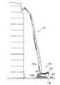
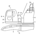
図1に、作業機械の一例を示す。図示の作業機械100は、高層ビルの解体作業などに用いられる解体機である。アタッチメント101を延ばせば、その先端部分は高層階にまで到達する。
FIG. 1 shows an example of a work machine. The illustrated
作業機械100は、左右両側に一対のクローラ102aを有する下部走行体102に旋回自在に搭載された機械本体103を備え、その機械本体103に、アタッチメント101やカウンタウエイト104、キャブ105(スイングキャブ)などが設置されている。
The
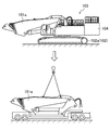
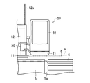
このような大型の作業機械100の場合、そのままでは輸送できないため、アタッチメント101やカウンタウエイト104などは分解して輸送される。例えば、アタッチメント101は複数のパーツに分解され、その基端部分を構成しているメインブーム101aは、図2に示すように、クレーン等を用いて機械本体103から取り外された後、トレーラーに積載して輸送される。
In the case of such a
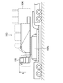
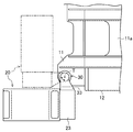
また、下部走行体102及び機械本体103については、図3に示すように、機械本体103から柵やカウンタウエイト104が取り外され、そして、下部走行体102では、両クローラ102aがカーボディ102bから取り外された状態で、トレーラに積載して輸送される。
Further, as shown in FIG. 3, for the lower traveling
その際、横幅の大きいカーボディ102bは、機械本体103に対して90°旋回させた状態で積載され、作業時に機械本体103よりも側方に張り出して位置するキャブ105は、旋回操作されて機械本体103の前方のスペースに収容される。そうすることで、下部走行体102等を輸送時の幅制限の範囲内に収めている。
At that time, the
ところが、輸送時には、幅制限だけでなく高さ制限hもあるため、キャブ105の高さが問題となる場合がある。
However, since there is not only a width restriction but also a height restriction h during transportation, the height of the
すなわち、作業時には、キャブ105の下方にクローラ102aが位置するため、キャブ105は、クローラ102aと接触しない高さに設置する必要がある。更に、キャブ105とクローラ102aとの間が狭いと、その間に鉄筋等を噛み込むおそれがあるため、キャブ105とクローラ102aとの間に十分なスペースを確保する必要がある。
In other words, since the
そのような限られた条件の下で、キャブ105を輸送時の高さ制限hの範囲内に収めなければならないため、キャブ105の大きさが制限される場合があり、機種によっては、キャブ105の室内が狭くなるなどの問題がある。
Under such limited conditions, the size of the
そこで、本発明の目的は、分解輸送時におけるキャブの高さ制限の問題が解消できる作業機械を提供することにある。 Therefore, an object of the present invention is to provide a work machine that can solve the problem of the cab height limitation during disassembly and transportation.
本発明の作業機械は、分解して輸送され、作業時に組み立てられる作業機械である。作業機械は、脱着可能な一対のクローラを有する下部走行体と、前記下部走行体の上に設置された機械本体と、前記機械本体の前部に脱着可能に支持されたアタッチメントと、前記機械本体の後部に脱着可能に支持されたカウンタウエイトと、前記機械本体の前隅部に支持装置を介して支持されたキャブと、を備え、前記キャブは、前記支持装置の作動により、前記機械本体よりも側方に張り出す作業位置と、前記機械本体から前記アタッチメントが取り外された状態において、前記作業位置から前記機械本体の前方に回り込んで位置する輸送位置と、に旋回するとともに、前記輸送位置において前記作業位置から降下される。 The work machine of the present invention is a work machine that is disassembled and transported and assembled during work. A work machine includes a lower traveling body having a pair of detachable crawlers, a machine main body installed on the lower traveling body, an attachment supported detachably on a front portion of the machine main body, and the machine main body A counterweight removably supported at the rear portion, and a cab supported by a support device at a front corner of the machine body, the cab being moved from the machine body by the operation of the support device. Swiveling to a working position projecting sideways and a transport position located around the front of the machine body from the work position in a state where the attachment is removed from the machine body, and the transport position At the working position.
このように構成された作業機械によれば、輸送時に作業位置から機械本体の前方に回り込んで位置する輸送位置では、キャブが作業位置から降下されるので、例えば、旋回しただけでは高さ制限を超えるサイズのキャブでも、作業時には、クローラとの間に十分なスペースを確保しながら、輸送時には、高さ制限の範囲内に収めることができる。 According to the work machine configured as described above, the cab is lowered from the work position at the transport position that is located around the front of the machine body during transport, so that, for example, the height is limited only by turning. Even if the cab exceeds the size, a sufficient space can be secured between the cab and the crawler during work, and the cab can be kept within the height limit during transportation.
具体的には、前記キャブの最上部が、あらかじめ設定された所定の高さに対して、前記作業位置では高くなり、前記輸送位置では同じか低くなる位置に構成するのが好ましい。 Specifically, it is preferable that the uppermost part of the cab is configured to be higher than the predetermined height set in advance at the working position and at the same or lower position at the transport position.
なお、ここでいう「キャブの最上部」とは、キャブ自体の最上部に限らずキャブやその備品を含めたキャブ全体の最上部をいう。例えば、キャブの上部にキャブガードが取り付けられていて、キャブガードがキャブの上方に突出しているときには、キャブガードの最上部がキャブの最上部に相当する。更にここでいう「所定の高さ」とは、例えば、道路交通法により定められた陸送時の輸送時制限高さが相当する。 The “top of the cab” here is not limited to the top of the cab itself, but the top of the entire cab including the cab and its equipment. For example, when the cab guard is attached to the upper part of the cab and the cab guard protrudes above the cab, the uppermost part of the cab guard corresponds to the uppermost part of the cab. Further, the “predetermined height” referred to here corresponds to, for example, a restricted height during transportation defined by the Road Traffic Law.
また、前記機械本体の少なくとも安全柵を除いた最大高さ位置は、前記あらかじめ設定された所定の高さであるのが好ましい。 Moreover, it is preferable that the maximum height position excluding at least the safety fence of the machine body is the predetermined height set in advance.
そうすれば、例えば、輸送時に、機械本体からアタッチメントやカウンタウエイトを取り外すことで機械本体を所定の高さ一杯まで高くできる。従って、機械本体3の内部空間を十二分に確保でき、作業時には機械本体3の高さよりキャブ20を高く位置させることで作業視界を良好にすることができ、輸送時には機械本体3の高さ以下に低くキャブ20を位置させることができる。
If it does so, for example, at the time of transportation, the machine body can be raised to a predetermined height by removing the attachment and the counterweight from the machine body. Therefore, the internal space of the machine
より具体的には、前記支持装置は、中心線が鉛直方向に延びるように前記機械本体に固定された円筒状の内筒部と、前記内筒部の外側にスライド自在に嵌め込まれ、前記キャブをブラケットを介して支持する円筒状の外筒部と、前記内筒部に収容され、前記中心線に沿ってロッド部及びシリンダ部が配置された油圧シリンダと、を有し、前記外筒部が、前記内筒部に対して、回動するとともに、前記油圧シリンダの駆動によって上下動するように構成することができる。 More specifically, the support device is slidably fitted to a cylindrical inner cylinder portion fixed to the machine body so that a center line extends in the vertical direction, and to the outside of the inner cylinder portion, and the cab A cylindrical outer tube portion that supports the outer cylinder portion, and a hydraulic cylinder that is accommodated in the inner tube portion and that has a rod portion and a cylinder portion disposed along the center line. However, it can be configured to rotate with respect to the inner cylinder portion and to move up and down by driving the hydraulic cylinder.
そうすれば、比較的簡素な構造の支持装置でキャブの旋回及び昇降の動作を行うことができる。 If it does so, the operation | movement of turning and raising / lowering of a cab can be performed with the support apparatus of a comparatively simple structure.
この場合、前記内筒部及び前記外筒部のいずれか一方に、前記シリンダ部が取り付けられ、前記内筒部及び前記外筒部の他方に、前記ロッド部の突端を受け止める軸受部が設けられ、前記油圧シリンダの収縮時に、前記ロッド部の突端が前記軸受部から離れて位置するようにするとよい。 In this case, the cylinder part is attached to one of the inner cylinder part and the outer cylinder part, and a bearing part that receives the protruding end of the rod part is provided on the other of the inner cylinder part and the outer cylinder part. When the hydraulic cylinder contracts, the protruding end of the rod portion may be positioned away from the bearing portion.
そうすれば、油圧シリンダの収縮時には、ロッド部の突端が軸受部から離れて位置しているため、その状態でキャブを旋回操作することにより、比較的弱い力で旋回させることができる。従って、機械力に頼らず、手動でもキャブを容易に旋回操作できるし、構造を簡素にできる。旋回時に油圧シリンダに過度な負荷が加わらないため、耐久性にも優れる。 Then, when the hydraulic cylinder is contracted, the protruding end of the rod portion is located away from the bearing portion, so that the cab can be turned with a relatively weak force by turning the cab in this state. Therefore, the cab can be easily swiveled manually without depending on the mechanical force, and the structure can be simplified. Since excessive load is not applied to the hydraulic cylinder during turning, it has excellent durability.
本発明によれば、分解輸送時におけるキャブの高さ制限の問題が解消できる。 According to the present invention, the problem of the cab height limitation during disassembly and transportation can be solved.
以下、本発明の実施形態を図面に基づいて詳細に説明する。ただし、以下の説明は、本質的に例示に過ぎず、本発明、その適用物あるいはその用途を制限するものではない。 Hereinafter, embodiments of the present invention will be described in detail with reference to the drawings. However, the following description is merely illustrative in nature and does not limit the present invention, its application, or its use.
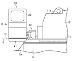
図4に、本発明を適用した解体機1(作業機械の一例)を示す。この解体機1は、高層ビルの解体作業向けに設計された大型機種である。解体機1は、そのままでは輸送できないため、分解して輸送され、作業現場で組み立てて使用される。
FIG. 4 shows a dismantling machine 1 (an example of a work machine) to which the present invention is applied. The
解体機1は、下部走行体2と、機械本体3とで構成されている。下部走行体2は、前後方向よりも幅方向の方が長いカーボディ5と、一対のクローラ6,6とを有している。各クローラ6は、カーボディ5の幅方向側の各端部に設けられた連結部5aに、脱着可能に取り付けられている(図10参照)。各クローラ6は、輸送時にはカーボディ5から取り外される。
The
機械本体3は、カーボディ5の上に旋回ベアリングを介して旋回自在に支持されたフレーム11や、そのフレーム11の上に設置された機械収容部12やカウンタウエイト13などを有している。フレーム11にはまた、アタッチメント14やキャブ20が支持されている。フレーム11の主体は、肉厚な底板で構成されている。
The
アタッチメント14は、圧砕機14aやアーム14b、中間部位の2箇所で屈曲可能なロングブーム14cなどで構成されている。アタッチメント14は、機械本体3の前部中央に起伏自在に支持されている。アタッチメント14は、分解可能な複数のパーツで構成されており、輸送時には、各パーツに分解される。
The
例えば、アタッチメント14の基端部分を構成しているメインブーム14dは、ブームシリンダ等とともに、フレーム11に設けられたアタッチメント支持部11aに脱着可能に支持されている。輸送時には、このメインブーム14dを含め、アタッチメント14は機械本体3から取り外される。
For example, the
機械収容部12の周囲はガードで覆われており、その内部にエンジンや油圧ポンプなどの駆動機器、燃料タンク等が収容されている。ガードの上部には、安全柵12aが着脱可能に取り付けられている。安全柵12aは、高さを抑制するために輸送時には取り外される。安全柵12は取り外されずに折り畳まれる場合もある。高重量のカウンタウエイト13は、アタッチメント14と前後のバランスを保つために機械本体3の後部に設置されている。カウンタウエイト13も輸送時には分解して輸送される。
The periphery of the
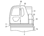
図5、図6に詳しく示すように、キャブ20は、箱形の運転室であり、フレーム11の左側の前隅部に支持装置30を介して支持されている。
As shown in detail in FIGS. 5 and 6, the
具体的には、キャブ20は、キャブベース21と、キャブベース21の上に設置され、箱形の運転室を区画するキャブカバー22とを有している。この解体機1のキャブ20は、更に、キャブカバー22の後方にチルト装置23を有している。作業時には、このチルト装置23により、キャブ20の前部が斜め上方に向くように、キャブ20をキャブベース21ごと傾動させことができる。
Specifically, the
図7に実線で示すように、作業時には、キャブ20は、機械本体3よりも側方に張り出した位置(作業位置)に固定される。そして、図5、図6に示すように、作業位置では、キャブベース21の下面(キャブ20の最下部、その高さ位置を符号Hで示す)は、少なくとも機械本体3の下面、具体的にはフレーム11の下面よりも上側に位置するように設定されている。
As shown by a solid line in FIG. 7, the
そして、輸送時に、アタッチメント支持部11aからアタッチメント14が取り外されると、機械本体3の前方にスペースが生じる。このスペースを利用して、キャブ20は、支持装置30の作動により、図7に仮想線で示すように、機械本体3の前方に回り込んだ位置(輸送位置)に旋回され、固定される。
When the
図8、図9に詳しく示すように、輸送位置では、支持装置30の作動により、キャブ20はキャブベース21とともに作業位置から降下される。
As shown in detail in FIGS. 8 and 9, in the transport position, the
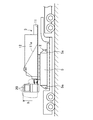
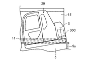
具体的には、図10に示すように、輸送位置では、キャブ20やキャブベース21は、作業位置(仮想線)よりも下方に位置しており、キャブ20の最上部は、道路交通法により定められた陸送時の輸送時制限高さの上限(高さ制限h)よりも低く位置している。従って、輸送時には、高さ制限hの範囲内にキャブ20を収めることができるので、輸送時におけるキャブの高さ制限の問題が解消できる。
Specifically, as shown in FIG. 10, at the transport position, the
しかも、上述したように、輸送時の機械本体3には、アタッチメント14やカウンタウエイト13は含まれていないので、機械本体3を高さ制限h一杯まで高くできる。従って、機械本体3の内部空間を十二分に確保でき、作業時には機械本体3の高さよりキャブ20を高く位置させることで作業視界を良好にすることができ、輸送時には機械本体3の高さ以下に低くキャブ20を位置させることができる。
In addition, as described above, since the
同時に、輸送位置でのキャブ20の最下部も、作業位置での高さ位置Hよりも低く位置しており、キャブベース21の下面がフレーム11の下面よりも下側に入り込んでいる。従って、キャブ20の高さ方向における制約が緩和されるため、キャブ20を高さ制限hの範囲内に収めつつ、従来であれば実現できなかった大きさのキャブも設置できるようになる。
At the same time, the lowermost part of the
輸送時にはまた、図10に示すように、機械本体3からは、カウンタウエイト13や安全柵12a等が取り外され、下部走行体2からは両クローラ6,6が取り外される。また、キャブの上部にキャブガードが着脱可能に取り付けられている場合には、キャブガードが取り外される場合もある。そして、カーボディ5の長手側(幅方向側)が、機械本体3の長手側と重なるように、下部走行体2に対して機械本体3が90°旋回される。そうして幅寸法や高さ寸法を小さくした状態で、下部走行体2及び機械本体3は、トレーラに積載される。
Also during transportation, as shown in FIG. 10, the
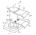
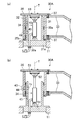
(支持装置)
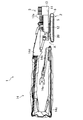
図11、図12に、本実施形態の支持装置30を示す。支持装置30は、内筒部31や外筒部32、ブラケット33、油圧シリンダ34などで構成されている。支持装置30は、ブラケット33を介してキャブ20を片持ち状に支持しており、キャブ20の旋回及び昇降の動作は支持装置30によって行われる。
(Supporting device)
11 and 12 show the
内筒部31は、下端部分に取付基部31aを有する円筒状の強度部材であり、その中心線Tが鉛直方向に延びるように、取付基部31aがフレーム11に固定されている。外筒部32は、内筒部31よりも直径が大きい円筒状の強度部材であり、内筒部31の外側に上下2つのブッシュ35a,35bを介して上下方向及び円周方向にスライド自在に嵌め込まれている。そのため、下側のブッシュ35bは、外筒部32の下端の下側にも面しており、半径方向である、内筒部31と外筒部32との間に介在するだけでなく、軸方向である、外筒部32の下端と取付基部31aの上面との間にも介在している。
The
外筒部32の上端には、開口を塞ぐように蓋板36が固定されている。外筒部32の側面には、一対のフランジ部37,37が設けられている。これらフランジ部37,37は、上下に離れて位置し、互いに対向するように外筒部32の側面から突出している。これらフランジ部37の各々に、キャブ20の後部に取り付けられ、側方に突き出すように延びるブラケット33が締結して固定されている。
A
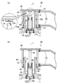
油圧シリンダ34は、シリンダ部38やロッド部39などで構成されており、内筒部31に収容されている。シリンダ部38は、筒状の耐圧容器であり、その中心が内筒部31の中心線Tに沿って延びるように、その下端部分が取付基部31aに一体に取り付けられている。封止されたシリンダ部38の下端部分には、油圧配管が接続されたオイルポート38aが設けられている。
The
ロッド部39は、その下端部分からシリンダ部38に挿入されている。ロッド部39の下端部分には、シリンダ部38の内周面に圧接して摺動するピストン39aが設けられている。シリンダ部38の上端部分には、ロッド部39をスライド自在に支持するシリンダキャップ40が取り付けられている。
The
オイルポート38aを通じてシリンダ部38に圧油が出入りすることによってピストン39aが変位し、中心線Tに沿って配置されたロッド部39は上下にスライドする。詳しくは、ロッド部39は、ピストン39aが最下点に位置し、その突端側の一部がシリンダ部38から突出した収縮位置(図12の(a)に示す)と、ピストン39aが最上点に位置し、その突端側の大部分がシリンダ部38から突出した伸張位置(図12の(b)に示す)との間でスライドする。
When the pressure oil enters and exits the
収縮位置では、ロッド部39の突端は、支持装置30の内部の空間に位置している。そのロッド部39の突端には、球面状に突出した係合部41が設けられている。収縮時に、ロッド部39の上方に離れて位置する蓋板36の内面の部分には、軸受部42が設けられており、その軸受部42に、係合部41に対応して下向きに球面状に凹む凹部42aが形成されている。
In the contracted position, the protruding end of the
外筒部32は、油圧シリンダ34の駆動によって上下動する。すなわち、収縮位置にある油圧シリンダ34に圧油が供給されると、ロッド部39が上昇して、その突端が軸受部42に突き当たり、係合部41は凹部42aに受け入れられる。更にロッドが上昇することで、伸張位置に至るまで外筒部32が持ち上げられる。そして、伸張位置にある油圧シリンダ34から圧油が除去されれば、キャブ20等の荷重を受けてロッド部39とともに外筒部32が降下し、収縮位置に至る。
The
外筒部32は、保持機構により、作業位置での伸張位置及び輸送位置での収縮位置の各位置に保持される。例えば、この支持装置30では、保持機構として、ピン43とピン孔44,45とが設けられている。具体的には、図12に仮想線で示すように、外筒部32の周面に外ピン孔44が1つ形成されており、内筒部31の周面には、上下方向及び周方向に離れた位置に内ピン孔45が2つ形成されている。なお、便宜上、図12の各ピン孔44,45は周方向の配置をずらして表している。
The
外ピン孔44及び各内ピン孔45は、作業位置での伸張位置及び輸送位置での収縮位置の各位置で、互いに重なってピン43が差し込めるように配置されている。これらピン孔44,45にピン43を差し込むことで、外筒部32は保持機構によって各位置に保持される。
The
従って、この解体機1では、支持装置30を操作することにより、作業位置においてはキャブ20を相対的に高位置に支持でき、輸送位置においてはキャブ20を相対的に低位置に支持できる。その結果、作業時においてはキャブ20の十分な高さを確保しつつ、キャブ20を高さ制限の範囲内に収めて分解輸送できる。
Therefore, in this dismantling
特に、この支持装置30の場合、手動操作で、容易にキャブ20が旋回できるようになっている。
In particular, in the case of this
具体的には、収縮位置では、ロッド部39の突端が軸受部42から離れているため、その状態でキャブ20を旋回操作することにより、比較的弱い力で旋回させることができる。従って、機械力に頼らず、手動でもキャブ20を容易に旋回操作できるし、構造を簡素にできる。旋回時に油圧シリンダ34に過度な負荷が加わらないため、耐久性にも優れる。
Specifically, in the contracted position, the protruding end of the
しかも、外筒部32は、球面状の係合部41と凹部42aとを介してロッド部39に支持される。従って、外筒部32が多少がたつくようなことがあっても、係合部41と凹部42aとが相対的にずれるため、ロッド部39を曲げるような負荷がロッド部39に作用せずに済む。
Moreover, the
(第1変形例)
図13に、上述した支持装置30の変形例を示す。本変形例の支持装置30Aでは、従来の油圧シリンダ34をそのまま用いて構成されている。なお、基本的構成は上述した支持装置30と同じであるため、同様の機能を有する構成については同じ符号を用い、その説明は省略する(他の変形例も同様)。
(First modification)
In FIG. 13, the modification of the
具体的には、取付基部31aの上面に下ブラケット51が設けられ、蓋板36の内面には、ベアリング装置53を介して、下ブラケット51と上下に対向して上ブラケット52が設けられている。そして、シリンダ部38の下端部分が下ブラケット51に回動可能に軸支され、ロッド部39の突端部分が上ブラケット52に回動可能に軸支されている。
Specifically, a
従って、この支持装置30Aでも、ベアリング装置53の作動により、外筒部32を内筒部31に対して回動させ、キャブ20を旋回させることができる。そして、油圧シリンダ34の駆動により、外筒部32を内筒部31に対して上下動させ、キャブ20を昇降させることができる。
Therefore, also in this
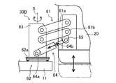
(第2変形例)
図14に、上述した支持装置30の変形例を示す。本変形例の支持装置30Bでは、キャブ20の昇降にリンク機構61が用いられている。
(Second modification)
In FIG. 14, the modification of the
具体的には、この支持装置30Bは、リンク機構61や基部62、旋回部63、油圧シリンダからなる作動部64などで構成されている。基部62は、機械本体3に設置されており、旋回部63は、基部62に、ベアリング機構62aを介して鉛直方向に延びる旋回軸Sまわりに旋回自在に支持されている。リンク機構61は、旋回部63に設けられていて、キャブ20を片持ち状に支持している。
Specifically, the
リンク機構61は、上下に並んで互いに平行に延びる上側アーム61a及び下側アーム61bを有している。これらアーム61a,61bの一端はキャブ20に横軸回りに回動可能に軸支され、他端は旋回部63に横軸回りに回動可能に軸支されている。下側アーム61bのキャブ20側の端部には、下方に突出するようにロッド連結部65が設けられている。
The
作動部64のシリンダ64aは、旋回部63における下側アーム61bの下方の部分に横軸回りに回動可能に軸支されており、作動部64のロッド64bは、ロッド連結部65に横軸回りに回動可能に軸支されている。
The
従って、この支持装置30Bでも、旋回部63を旋回操作することにより、キャブ20を作業位置と輸送位置の間で旋回させることができる。そして、作動部64の駆動により、作動部64とリンク機構61とが協働して、キャブ20を昇降させることができる。
Therefore, also in this
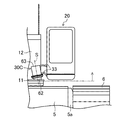
(第3変形例)
図15、図16に、上述した支持装置30の変形例を示す。本変形例の支持装置30Cでは、旋回軸Sが傾いている。そうすることにより、作業位置から輸送位置にキャブ20を旋回させることで、キャブ20の位置が降下する。
(Third Modification)
15 and 16 show a modification of the
具体的には、この支持装置30Cは、基部62や旋回部63、ブラケット33などで構成されている。基部62は、機械本体3に設置されており、旋回部63は、この基部62に旋回自在に支持されている。支持装置30Cは、その上部が機械本体3の中央側に傾いた状態で固定されており、旋回部63が旋回する旋回軸Sは、機械本体3の幅方向を中央側から端側に向かって下向きに傾斜して延びている。
Specifically, the
キャブ20は、ブラケット33を介して旋回部63に片持ち状に支持されている。図15に示すように、作業位置では、キャブベース21が水平になるように構成されている。
The
支持装置30Cの旋回軸Sが傾いているため、キャブ20を輸送位置に向かって旋回操作すると、キャブ20は次第に傾いていく。そうして、図16に示すように、輸送位置に至ると、キャブ20はその前側部分が下向きに傾いた状態で作業位置よりも低く位置する。
Since the turning axis S of the
従って、この支持装置30Cによれば、単に旋回操作を行うだけで、キャブ20の旋回と昇降とが同時に行える。油圧シリンダ34等の駆動装置が不要になるため、構造の簡素化も図れる。
Therefore, according to the
なお、本発明にかかる作業機械は、上述した実施形態に限定されず、それ以外の種々の構成をも包含する。 In addition, the working machine according to the present invention is not limited to the above-described embodiment, and includes various other configurations.
例えば、上述した実施形態では、作業機械として解体機を例示したが、クレーンやショベル等、他の作業機械にも適用できる。また、支持装置における油圧シリンダの取付は逆に、すなわち、シリンダ部38を外筒部32の側に取り付け、ロッド部39を内筒部31の側に取り付けてもよい。
For example, in the above-described embodiment, the dismantling machine is exemplified as the work machine, but the present invention can also be applied to other work machines such as a crane and an excavator. Further, the mounting of the hydraulic cylinder in the support device may be reversed, that is, the
1 解体機(作業機械)
2 下部走行体
3 機械本体
6 クローラ
14 アタッチメント
20 キャブ
30 支持装置
1 Demolition machine (work machine)
2 Lower traveling
Claims (7)
脱着可能な一対のクローラを有する下部走行体と、
前記下部走行体の上に設置された機械本体と、
前記機械本体の前部に脱着可能に支持されたアタッチメントと、
前記機械本体の後部に脱着可能に支持されたカウンタウエイトと、
前記機械本体の前隅部に支持装置を介して支持されたキャブと、
を備え、
前記キャブは、
前記支持装置の作動により、
前記機械本体よりも側方に張り出す作業位置と、
前記機械本体から前記アタッチメントが取り外された状態において、前記作業位置から前記機械本体の前方に回り込んで位置する輸送位置と、
に旋回するとともに、
前記輸送位置において前記作業位置から降下される作業機械。 A work machine that is disassembled and transported and assembled during work,
A lower traveling body having a pair of detachable crawlers;
A machine body installed on the lower traveling body;
An attachment supported detachably at the front of the machine body;
A counterweight removably supported at the rear of the machine body;
A cab supported via a support device at the front corner of the machine body;
With
The cab is
By operation of the support device,
A working position projecting laterally from the machine body;
In a state where the attachment is removed from the machine body, a transport position that wraps around from the working position to the front of the machine body, and
And turn to
A work machine that is lowered from the work position at the transport position.
前記キャブの上面が、あらかじめ設定された所定の高さに対して、前記作業位置では高くなり、前記輸送位置では同じか低くなる位置に構成される作業機械。 The work machine according to claim 1,
A work machine configured such that an upper surface of the cab is higher at a predetermined height than the predetermined height at the work position and is the same or lower at the transport position.
前記機械本体の少なくとも安全柵を除いた最大高さ位置が、前記あらかじめ設定された所定の高さであることを特徴とする作業機械。 The work machine according to claim 2,
A working machine, wherein a maximum height position excluding at least a safety fence of the machine body is the predetermined height set in advance.
前記支持装置は、
中心線が鉛直方向に延びるように前記機械本体に固定された円筒状の内筒部と、
前記内筒部の外側にスライド自在に嵌め込まれ、前記キャブをブラケットを介して支持する円筒状の外筒部と、
前記内筒部に収容され、前記中心線に沿ってロッド部及びシリンダ部が配置された油圧シリンダと、
を有し、
前記外筒部が、前記内筒部に対して、回動するとともに、前記油圧シリンダの駆動によって上下動する作業機械。 In the work machine according to any one of claims 1 to 3,
The support device is
A cylindrical inner cylinder fixed to the machine body such that the center line extends in the vertical direction;
A cylindrical outer tube portion that is slidably fitted to the outside of the inner tube portion and supports the cab via a bracket;
A hydraulic cylinder housed in the inner cylinder portion, and a rod portion and a cylinder portion arranged along the center line;
Have
A work machine in which the outer cylinder part rotates relative to the inner cylinder part and moves up and down by driving the hydraulic cylinder.
前記内筒部及び前記外筒部のいずれか一方に、前記シリンダ部が取り付けられ、
前記内筒部及び前記外筒部の他方に、前記ロッド部の突端を受け止める軸受部が設けられ、
前記油圧シリンダの収縮時に、前記ロッド部の突端が前記軸受部から離れて位置する作業機械。 The work machine according to claim 4,
The cylinder part is attached to either the inner cylinder part or the outer cylinder part,
On the other of the inner cylinder part and the outer cylinder part, a bearing part for receiving the protruding end of the rod part is provided,
A working machine in which a protruding end of the rod portion is located away from the bearing portion when the hydraulic cylinder contracts.
前記支持装置は、
前記機械本体に設置された基部と、
前記基部に、鉛直方向に延びる旋回軸まわりに旋回自在に支持された旋回部と、
前記旋回部に設けられ、当該キャブを昇降可能に支持するリンク機構と、
前記旋回部と前記キャブとの間に設けられ、前記リンク機構と協働して前記キャブを昇降させる油圧シリンダと、
を有している作業機械。 In the work machine according to any one of claims 1 to 3,
The support device is
A base installed in the machine body;
A swivel portion supported by the base portion so as to be turnable around a swivel axis extending in a vertical direction;
A link mechanism provided in the swivel unit and supporting the cab so as to be movable up and down;
A hydraulic cylinder provided between the swivel unit and the cab and moving the cab up and down in cooperation with the link mechanism;
Having working machine.
前記支持装置は、
前記機械本体に設置された基部と、
前記基部に旋回自在に支持され、前記キャブをブラケットを介して支持する旋回部と、
を有し、
前記旋回部が、前記機械本体の幅方向を中央側から端側に向かって下向きに傾斜して延びる旋回軸まわりに旋回する作業機械。 In the work machine according to any one of claims 1 to 3,
The support device is
A base installed in the machine body;
A swivel portion that is pivotally supported by the base and supports the cab via a bracket;
Have
A work machine in which the swivel part swivels about a swivel axis extending in a downwardly inclined direction from the center side toward the end side in the width direction of the machine body.
Priority Applications (1)
| Application Number | Priority Date | Filing Date | Title |
|---|---|---|---|
| JP2012182703A JP5991072B2 (en) | 2012-08-21 | 2012-08-21 | Work machine |
Applications Claiming Priority (1)
| Application Number | Priority Date | Filing Date | Title |
|---|---|---|---|
| JP2012182703A JP5991072B2 (en) | 2012-08-21 | 2012-08-21 | Work machine |
Publications (2)
| Publication Number | Publication Date |
|---|---|
| JP2014040722A true JP2014040722A (en) | 2014-03-06 |
| JP5991072B2 JP5991072B2 (en) | 2016-09-14 |
Family
ID=50393168
Family Applications (1)
| Application Number | Title | Priority Date | Filing Date |
|---|---|---|---|
| JP2012182703A Expired - Fee Related JP5991072B2 (en) | 2012-08-21 | 2012-08-21 | Work machine |
Country Status (1)
| Country | Link |
|---|---|
| JP (1) | JP5991072B2 (en) |
Cited By (5)
| Publication number | Priority date | Publication date | Assignee | Title |
|---|---|---|---|---|
| CN105523091A (en) * | 2016-03-03 | 2016-04-27 | 中国矿业大学 | Automatic balancing control device and method for truck carriage based on anticipatory control |
| JP2017506202A (en) * | 2014-02-07 | 2017-03-02 | マニタウォック クレイン カンパニーズ, エルエルシーManitowoc Crane Companies, Llc | Tilting mechanism for crane |
| WO2022227643A1 (en) * | 2021-12-02 | 2022-11-03 | 江苏徐工工程机械研究院有限公司 | Modular excavator |
| US20230416058A1 (en) * | 2020-12-08 | 2023-12-28 | Kobelco Construction Machinery Co., Ltd. | Crane |
| US12618218B2 (en) | 2021-12-02 | 2026-05-05 | Jiangsu Xcmg Construction Machinery Research Institute Ltd. | Modular excavator |
Citations (8)
| Publication number | Priority date | Publication date | Assignee | Title |
|---|---|---|---|---|
| JPH07156657A (en) * | 1993-12-01 | 1995-06-20 | Shin Caterpillar Mitsubishi Ltd | Cab device in construction machine for road work |
| JPH07304596A (en) * | 1994-05-13 | 1995-11-21 | Toyo Umpanki Co Ltd | Forklift truck |
| JP2000281277A (en) * | 1999-03-29 | 2000-10-10 | Kobelco Contstruction Machinery Ltd | Cabin fitting device for construction machine |
| JP2005105521A (en) * | 2003-09-26 | 2005-04-21 | Kobelco Contstruction Machinery Ltd | Working machine |
| JP2006168941A (en) * | 2004-12-17 | 2006-06-29 | Kobelco Cranes Co Ltd | Crawler crane |
| JP2007210468A (en) * | 2006-02-09 | 2007-08-23 | Kobelco Contstruction Machinery Ltd | Cabin lifting device |
| JP2009002141A (en) * | 2007-04-19 | 2009-01-08 | Wirtgen Gmbh | Automobile construction equipment |
| JP2009040599A (en) * | 2007-08-10 | 2009-02-26 | Tadano Ltd | Mobile crane |
-
2012
- 2012-08-21 JP JP2012182703A patent/JP5991072B2/en not_active Expired - Fee Related
Patent Citations (8)
| Publication number | Priority date | Publication date | Assignee | Title |
|---|---|---|---|---|
| JPH07156657A (en) * | 1993-12-01 | 1995-06-20 | Shin Caterpillar Mitsubishi Ltd | Cab device in construction machine for road work |
| JPH07304596A (en) * | 1994-05-13 | 1995-11-21 | Toyo Umpanki Co Ltd | Forklift truck |
| JP2000281277A (en) * | 1999-03-29 | 2000-10-10 | Kobelco Contstruction Machinery Ltd | Cabin fitting device for construction machine |
| JP2005105521A (en) * | 2003-09-26 | 2005-04-21 | Kobelco Contstruction Machinery Ltd | Working machine |
| JP2006168941A (en) * | 2004-12-17 | 2006-06-29 | Kobelco Cranes Co Ltd | Crawler crane |
| JP2007210468A (en) * | 2006-02-09 | 2007-08-23 | Kobelco Contstruction Machinery Ltd | Cabin lifting device |
| JP2009002141A (en) * | 2007-04-19 | 2009-01-08 | Wirtgen Gmbh | Automobile construction equipment |
| JP2009040599A (en) * | 2007-08-10 | 2009-02-26 | Tadano Ltd | Mobile crane |
Cited By (6)
| Publication number | Priority date | Publication date | Assignee | Title |
|---|---|---|---|---|
| JP2017506202A (en) * | 2014-02-07 | 2017-03-02 | マニタウォック クレイン カンパニーズ, エルエルシーManitowoc Crane Companies, Llc | Tilting mechanism for crane |
| CN105523091A (en) * | 2016-03-03 | 2016-04-27 | 中国矿业大学 | Automatic balancing control device and method for truck carriage based on anticipatory control |
| US20230416058A1 (en) * | 2020-12-08 | 2023-12-28 | Kobelco Construction Machinery Co., Ltd. | Crane |
| US12358762B2 (en) * | 2020-12-08 | 2025-07-15 | Kobelco Construction Machinery Co., Ltd. | Crane |
| WO2022227643A1 (en) * | 2021-12-02 | 2022-11-03 | 江苏徐工工程机械研究院有限公司 | Modular excavator |
| US12618218B2 (en) | 2021-12-02 | 2026-05-05 | Jiangsu Xcmg Construction Machinery Research Institute Ltd. | Modular excavator |
Also Published As
| Publication number | Publication date |
|---|---|
| JP5991072B2 (en) | 2016-09-14 |
Similar Documents
| Publication | Publication Date | Title |
|---|---|---|
| CN107257772B (en) | Moving device for counterweight | |
| JP5184407B2 (en) | Working machine | |
| JP2014501655A (en) | Mobile work machine with support structure | |
| JP5991072B2 (en) | Work machine | |
| EP2829499A1 (en) | Outrigger connection locking device | |
| EP2354327A1 (en) | Demolition machine with compact transport configuration | |
| WO2016129262A1 (en) | Crawler crane car body weight supporting device | |
| JP2014129161A (en) | Counterweight device of construction machine and construction machine | |
| JP2010058874A (en) | High lift work vehicle | |
| JP2007205100A (en) | Body frame of construction machinery and the construction machinery | |
| JP2020029320A (en) | Counterweight attaching/detaching device | |
| JP6539602B2 (en) | Crawler-type forklift | |
| JP4494287B2 (en) | Generator-equipped work machine | |
| JP5454308B2 (en) | crane | |
| JP2012197155A (en) | Crawler crane | |
| JP2009107774A (en) | Mobile crane | |
| JP4746642B2 (en) | Working unit structure | |
| JP4648962B2 (en) | Working unit structure | |
| JP6607224B2 (en) | Hoisting device | |
| JP2013075753A (en) | Outrigger device | |
| JP3999697B2 (en) | Outrigger jack | |
| JP7452399B2 (en) | crane | |
| JP7684874B2 (en) | pile driver | |
| JP7720247B2 (en) | Outrigger device | |
| JP7098938B2 (en) | Loadable truck crane |
Legal Events
| Date | Code | Title | Description |
|---|---|---|---|
| A621 | Written request for application examination |
Free format text: JAPANESE INTERMEDIATE CODE: A621 Effective date: 20150618 |
|
| A977 | Report on retrieval |
Free format text: JAPANESE INTERMEDIATE CODE: A971007 Effective date: 20160411 |
|
| A131 | Notification of reasons for refusal |
Free format text: JAPANESE INTERMEDIATE CODE: A131 Effective date: 20160419 |
|
| A521 | Request for written amendment filed |
Free format text: JAPANESE INTERMEDIATE CODE: A523 Effective date: 20160617 |
|
| TRDD | Decision of grant or rejection written | ||
| A01 | Written decision to grant a patent or to grant a registration (utility model) |
Free format text: JAPANESE INTERMEDIATE CODE: A01 Effective date: 20160719 |
|
| A61 | First payment of annual fees (during grant procedure) |
Free format text: JAPANESE INTERMEDIATE CODE: A61 Effective date: 20160801 |
|
| R150 | Certificate of patent or registration of utility model |
Ref document number: 5991072 Country of ref document: JP Free format text: JAPANESE INTERMEDIATE CODE: R150 |
|
| LAPS | Cancellation because of no payment of annual fees |