JP2014026041A - Exposure device and exposure method - Google Patents
Exposure device and exposure method Download PDFInfo
- Publication number
- JP2014026041A JP2014026041A JP2012164879A JP2012164879A JP2014026041A JP 2014026041 A JP2014026041 A JP 2014026041A JP 2012164879 A JP2012164879 A JP 2012164879A JP 2012164879 A JP2012164879 A JP 2012164879A JP 2014026041 A JP2014026041 A JP 2014026041A
- Authority
- JP
- Japan
- Prior art keywords
- exposure
- alignment
- unit
- mask
- turned
- Prior art date
- Legal status (The legal status is an assumption and is not a legal conclusion. Google has not performed a legal analysis and makes no representation as to the accuracy of the status listed.)
- Pending
Links
Images


Abstract
Description
本発明は、露光装置及び露光方法に用いて好適な技術に関する。 The present invention relates to a technique suitable for use in an exposure apparatus and an exposure method.
従来より、タッチパネルは、例えばATM、自動販売機、携帯情報端末、携帯ゲーム機、電子案内表示板、カーナビゲーション、携帯電話等に広く用いられている。
タッチパネルを液晶パネルの上に載せて使う従来方法に対して、タッチパネル機能を液晶パネルの中に一体化する方法の研究が盛んになっている。このタッチパネルと液晶パネルの一体化には、近年、タッチパネルセンサの薄型化と製造工程の簡単化のトレンドとして、インセル方式、オンセル方式と並んで、カバーガラスに直接パターニングする方法が検討されている。
Conventionally, touch panels have been widely used in, for example, ATMs, vending machines, portable information terminals, portable game machines, electronic guidance display boards, car navigation systems, mobile phones, and the like.
In contrast to the conventional method of using a touch panel on a liquid crystal panel, research on methods for integrating a touch panel function into a liquid crystal panel has become active. In recent years, for the integration of the touch panel and the liquid crystal panel, as a trend of thinning the touch panel sensor and simplifying the manufacturing process, a method of directly patterning the cover glass along with the in-cell method and the on-cell method has been studied.
現在市場に流通しているカバーガラスは、最終的に得られる製品のサイズ・形状にカットした後に強化処理を行っている。この工程を逆にすることが技術的障壁であり、カットされたカバーガラスヘのパターニングが行われている。即ち、強化処理を行った複数取りの大型ガラス基板を露光・パターニング後にカットすると、クラックが入るなどして製品化ができない、また、最終的に得られる製品の形状が矩形ではなくなり、単純にカットできないのが現状である。 The cover glass currently on the market is tempered after being cut into the final product size and shape. Reversing this process is a technical barrier, and the cut cover glass is patterned. In other words, if multiple large glass substrates that have undergone tempering treatment are cut after exposure and patterning, they cannot be commercialized due to cracks or the like, and the final product shape is not rectangular and is simply cut The current situation is not possible.
そこで、製品サイズ・形状にカットされたガラス基板に対して露光処理を行う露光装置が求められているが、そのような露光装置ではタクトタイムが大きくなってしまい、生産性向上の妨げとなっている。 Therefore, there is a demand for an exposure apparatus that performs an exposure process on a glass substrate that has been cut into a product size and shape. However, such an exposure apparatus increases the takt time, which hinders productivity improvement. Yes.
また、従来から、露光処理に必要な時間をより一層短縮する生産性の向上を安価に実現したいという要望は存在した。 Conventionally, there has been a desire to realize an improvement in productivity that can further reduce the time required for exposure processing at a low cost.
本発明は、このような従来の実情に鑑みて考案されたものであり、個別形状にカットされた基板などに対して露光処理を行う露光装置において、タクトタイムを短縮して、生産性を向上できる露光装置及び露光方法を提供することを目的とする。 The present invention has been devised in view of such conventional circumstances, and in an exposure apparatus that performs exposure processing on a substrate or the like cut into individual shapes, the tact time is shortened and the productivity is improved. An object of the present invention is to provide an exposure apparatus and an exposure method that can be used.
本発明の露光方法は、露光すべきパターンを有するマスクを保持するマスク保持部と、被露光材としてのワークを保持するワーク保持部と、前記マスク保持部と前記ワーク保持部とを相対的に駆動する駆動部と、前記マスクに形成されたマスク側アライメントマーク及び前記ワークに形成されたワーク側アライメントマークを検出可能なアライメントカメラと、アライメント開始可能であることを出力するレディ信号出力手段と、を備え前記ワーク上に前記マスクのパターンを露光転写する露光部が複数設けられ、これら複数の露光部において、それぞれ前記アライメントカメラによって検出された前記両アライメントマークのずれ量に基づいて、前記駆動部を駆動制御してアライメント動作を実行するための制御部が共通して設けられた露光装置における露光方法であって、
前記制御部が、前記レディ信号を出力している前記露光部のうち1つの露光部を選択してアライメント開始信号を出力する工程と、
この選択された露光部において、前記両アライメントマークのずれ量が露光転写時の所望のアライメント精度範囲以内となるよう前記駆動部によるアライメント動作を実行する工程とを有することにより上記課題を解決した。
本発明において、前記ワークが、予め強化処理が施されたガラス基板とされてなることがより好ましい。
本発明には、前記制御部が、前記選択した露光部において、前記駆動部に前記アライメント開始信号を出力する工程の後、前記レディ信号が再度出力される前に、前記レディ信号を出力している他の露光部を選択して前記アライメント開始信号を出力する工程を有することが可能である。
また、本発明の露光装置において、露光すべきパターンを有するマスクを保持するマスク保持部と、
被露光材としてのワークを保持するワーク保持部と、
前記マスク保持部と前記ワーク保持部とを相対的に駆動する駆動部と、
前記マスクに形成されたマスク側アライメントマーク及び前記ワークに形成されたワーク側アライメントマークを検出可能なアライメントカメラと、
アライメント開始可能であることを出力するレディ信号出力手段と、
を備え前記ワーク上に前記マスクのパターンを露光転写する露光部が複数設けられ、
これら複数の露光部において、それぞれ前記アライメントカメラによって検出された前記両アライメントマークのずれ量に基づいて、前記駆動部を駆動制御してアライメント動作を実行するための制御部が共通して設けられた露光装置であって、
前記制御部が、前記レディ信号を出力している前記露光部のうち1つの露光部を選択してアライメント開始信号を出力することで、
この選択された露光部において、前記両アライメントマークのずれ量が露光転写時の所望のアライメント精度範囲以内となるよう前記駆動部によるアライメント動作を実行する手段を採用することもできる。
また、前記ワークが、予め強化処理が施されたガラス基板とされてなることができる。
本発明においては、前記制御部が、前記選択した露光部において、前記駆動部に前記アライメント開始信号を出力した後、前記レディ信号が再度出力される前に、前記レディ信号を出力している他の露光部を選択して前記アライメント開始信号を出力することが望ましい。
さらに、前記ワーク保持部が複数のワークを保持可能とされることが可能である。
In the exposure method of the present invention, a mask holding part that holds a mask having a pattern to be exposed, a work holding part that holds a work as an exposed material, and the mask holding part and the work holding part are relatively A driving unit for driving, an alignment camera capable of detecting a mask-side alignment mark formed on the mask and a workpiece-side alignment mark formed on the workpiece, and a ready signal output means for outputting that alignment can be started; A plurality of exposure units that expose and transfer the mask pattern onto the workpiece, and the driving unit is configured to detect the alignment marks detected by the alignment camera in the plurality of exposure units. A common control unit for controlling the drive and executing the alignment operation. An exposure method in the apparatus,
The control unit selects one exposure unit from among the exposure units outputting the ready signal and outputs an alignment start signal;
The selected exposure unit has a step of performing an alignment operation by the drive unit so that the deviation amount of the alignment marks is within a desired alignment accuracy range at the time of exposure transfer.
In the present invention, it is more preferable that the workpiece is a glass substrate that has been pre-strengthened.
In the present invention, after the step of outputting the alignment start signal to the drive unit in the selected exposure unit, the control unit outputs the ready signal before the ready signal is output again. It is possible to include a step of selecting the other exposed portion and outputting the alignment start signal.
Further, in the exposure apparatus of the present invention, a mask holding unit that holds a mask having a pattern to be exposed;
A work holding unit for holding a work as an exposed material;
A drive unit that relatively drives the mask holding unit and the work holding unit;
An alignment camera capable of detecting a mask side alignment mark formed on the mask and a work side alignment mark formed on the workpiece;
Ready signal output means for outputting that alignment can be started;
A plurality of exposure portions for exposing and transferring the pattern of the mask on the workpiece.
In each of the plurality of exposure units, a common control unit is provided for controlling the driving unit to execute an alignment operation based on the shift amount of the alignment marks detected by the alignment camera. An exposure apparatus,
The control unit selects one of the exposure units that are outputting the ready signal and outputs an alignment start signal,
In the selected exposure unit, means for executing the alignment operation by the drive unit may be adopted so that the shift amount between the alignment marks is within a desired alignment accuracy range at the time of exposure transfer.
Moreover, the said workpiece | work can be made into the glass substrate by which the reinforcement | strengthening process was performed previously.
In the present invention, the control unit outputs the ready signal in the selected exposure unit after outputting the alignment start signal to the driving unit and before outputting the ready signal again. It is desirable to select the exposure portion and output the alignment start signal.
Furthermore, the workpiece holding unit can hold a plurality of workpieces.
本発明によれば、前記制御部が、前記レディ信号を出力している前記露光部のうち1つの露光部を選択してアライメント開始信号を出力することで、この選択された露光部において、前記両アライメントマークのずれ量が露光転写時の所望のアライメント精度範囲以内となるよう前記駆動部によるアライメント動作を実行することにより、共通となる制御部で複数の露光部を制御して露光を並列的におこなう際に、一つの露光部で駆動部によるアライメント中に、他の露光部でアライメントカメラからの画像に基づく駆動量の演算とアライメント信号の出力をおこなうことで、制御部を共通として複数の露光部を制御してタクトタイムを短縮するとともに装置の製造コストを削減するという効果を奏することができる。 According to the present invention, the control unit selects one exposure unit among the exposure units outputting the ready signal and outputs an alignment start signal. By performing the alignment operation by the drive unit so that the deviation amount of both alignment marks is within the desired alignment accuracy range at the time of exposure transfer, a common control unit controls a plurality of exposure units to perform exposure in parallel. When performing the operation, the exposure unit calculates the drive amount based on the image from the alignment camera and outputs the alignment signal during the alignment by the drive unit in one exposure unit. The exposure unit can be controlled to shorten the tact time and reduce the manufacturing cost of the apparatus.
本発明によれば、予め強化処理が施されたガラス基板に対しても、効率的に露光処理を行うことができ、安価にタクトタイムを短縮して、生産性を向上できる露光装置を提供することができる。 According to the present invention, there is provided an exposure apparatus that can efficiently perform an exposure process even on a glass substrate that has been subjected to a strengthening process in advance, can reduce takt time at low cost, and can improve productivity. be able to.
本発明においては、前記制御部が、前記選択した露光部において、前記駆動部に前記アライメント開始信号を出力した後、前記レディ信号が再度出力される前に、前記レディ信号を出力している他の露光部を選択して前記アライメント開始信号を出力することにより、共通の制御部における空き時間を短縮して、複数の露光部において効率的にタクトタイムを短縮することが可能となる。 In the present invention, the control unit outputs the ready signal in the selected exposure unit after outputting the alignment start signal to the driving unit and before outputting the ready signal again. By selecting the exposure unit and outputting the alignment start signal, it is possible to shorten the idle time in the common control unit and efficiently reduce the tact time in the plurality of exposure units.
以下、本発明に係る露光装置および露光方法の第1実施形態を、図面に基づいて説明する。
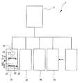
図1は、本実施形態における露光装置を示す模式図であり、図において、符号1は、露光装置である。
A first embodiment of an exposure apparatus and exposure method according to the present invention will be described below with reference to the drawings.
FIG. 1 is a schematic diagram showing an exposure apparatus according to the present embodiment. In the figure,
本実施形態における露光装置1は、制御部Cと、この制御部Cに接続された複数の露光部20,30,40,50・・・とを有する。露光部の台数は特に限定されるものではないが、本実施形態では、4台分のみを用いて説明する。
The
露光部20,露光部30,露光部40,露光部50は、いずれも、ほぼ等しい構成とされるため、代表して符号20を付したものについて説明する。また、これ以降の説明において、それぞれの露光部における構成は、符号20およびこれから派生した20番台の構成要素が、符号30,40,50およびこれから派生した30番台、40番台、50番台の構成要素に読み替えられるものとして記載する。
Since all of the
露光部20は、マスクMを保持するマスクステージ(マスク保持部)21と、ガラス基板(被露光材としてのワーク)Wを保持するワークステージ(ワーク保持部)22と、ワークステージ22をX軸,Y軸,Z軸方向に移動し、且つワークステージ22のチルト調整を行うワークステージ移動機構(駆動部)23と、アライメントカメラ24と、レディ信号出力手段25と、照射光学系26と、ワークWをロード・アンロードする搬送系27とを有する。
The
なお、ガラス基板W(以下、単に「ワークW」と称する。)は、露光時にはマスクMに対向配置され、このマスクMに描かれたマスクパターンを露光転写すべく表面(マスクMの対向面側)に感光剤が塗布されている。また、マスクMは、溶融石英からなり、長方形状に形成されている。 A glass substrate W (hereinafter simply referred to as “work W”) is disposed to face the mask M at the time of exposure, and the surface (opposite surface side of the mask M) for exposing and transferring the mask pattern drawn on the mask M. ) Is coated with a photosensitive agent. The mask M is made of fused quartz and has a rectangular shape.
マスクステージ(マスク保持部)21は、例えば、中央部に矩形形状の開口部が形成されるマスクステージベースと、マスクステージベースの開口部にX軸,Y軸,θ方向に移動可能に装着されるマスク保持枠(マスク保持部)と、マスク保持枠に取り付けられ、マスクMを吸着保持するチャック部と、マスク保持枠とチャック部とをX軸,Y軸,θ方向に移動させ、このマスク保持枠に保持されるマスクMの位置を調整するマスク位置調整機構(マスク駆動部)とを備えることができる。マスクステージベースは、Z軸移動装置によりZ軸方向に移動可能に支持され、ワークステージの上方に配置される。Z軸移動装置は、例えば、モータ及びボールねじ等からなる電動アクチュエータ、或いは空圧シリンダ等を備え、単純な上下動作を行うことにより、マスクステージを所定の位置まで昇降可能とする。また、マスク位置調整機構は、マスク保持枠のX軸方向に沿う一辺に取り付けられるY軸方向駆動装置と、マスク保持枠のY軸方向に沿う一辺に取り付けられる2台のX軸方向駆動装置とを備え、マスク保持枠をθ方向に移動(Z軸回りの回転)させることができる。 The mask stage (mask holding portion) 21 is mounted, for example, on a mask stage base having a rectangular opening at the center, and is movable in the X, Y, and θ directions at the opening of the mask stage base. The mask holding frame (mask holding portion), the chuck portion attached to the mask holding frame and holding the mask M by suction, and the mask holding frame and chuck portion are moved in the X-axis, Y-axis, and θ directions to move the mask. A mask position adjusting mechanism (mask driving unit) that adjusts the position of the mask M held by the holding frame can be provided. The mask stage base is supported by a Z-axis moving device so as to be movable in the Z-axis direction, and is disposed above the work stage. The Z-axis moving device includes, for example, an electric actuator including a motor and a ball screw, a pneumatic cylinder, or the like, and can move the mask stage up and down to a predetermined position by performing a simple vertical movement. The mask position adjusting mechanism includes a Y-axis direction driving device attached to one side along the X-axis direction of the mask holding frame, and two X-axis direction driving devices attached to one side along the Y-axis direction of the mask holding frame. The mask holding frame can be moved in the θ direction (rotated about the Z axis).
さらに、マスクステージ21の上側には、マスクMのアライメントマーク21aとワークWのアライメントマーク22aを撮像するためのアライメントカメラ24が設けられる。アライメントカメラ24は、移動機構を介してX軸,Y軸方向に移動可能に保持され、平面視してマスク保持枠内に配置可能である。
Further, an
ワークステージ(ワーク保持部)22は、は、ワークステージ移動機構23上に設置されており、ワークWをワークステージ22に保持するための吸着面を上面に有するワークチャックを備える。なお、ワークチャックは、真空吸着によりワークWを保持可能である。
The work stage (work holding unit) 22 is installed on the work
ワークステージ移動機構23は、ワークステージをY軸方向に移動させるY軸送り機構と、ワークステージ22をX軸方向に移動させるX軸送り機構と、ワークステージ22のチルト調整を行うと共に、ワークステージ22をZ軸方向に微動させるZ−チルト調整機構とを備える。なお、駆動部としてはマスクMとガラス基板Wとが相対移動可能であればよく、ワークステージ移動機構23およびマスク位置調整機構(マスク駆動部)とを含めた構成とすることができる。
The work
搬送系27は、所定位置にワークWをロードし、露光終了後にアンロード可能であればどのような構成でもよく、たとえば、多関節系のロボットハンドや、一方向に流れるコンベアなどが採用できる。なお、図1においては、模式的に搬送系27を示している。
The
レディ信号出力手段25は、所定位置にワークWが位置してアライメント開始可能である状態を出力するものとされ、搬送系27、あるいは、アライメントカメラ24などからの信号出力手段とすることができる。または、搬送系27の動作を制御部Cで制御する場合などには、制御部Cがレディ信号をONとして、制御部C自身をレディ信号出力手段25とすることもできる。
The ready signal output means 25 outputs a state in which the workpiece W is positioned at a predetermined position and alignment can be started, and can be a signal output means from the
照射光学系26は、露光照射が可能な構成であれば特に限定されることはないが、例えば、紫外線照射用の光源である例えば高圧水銀ランプと、この高圧水銀ランプから照射された光を集光する凹面鏡と、この凹面鏡の焦点近傍に切替え自在に配置された二種類のオプチカルインテグレータと、光路の向きを変えるための複数の平面ミラー及び球面ミラーと、この平面ミラーとオプチカルインテグレータとの間に配置されて照射光路を開閉制御する露光制御用シャッタとを備える構成とすることができる。
The irradiation
このように構成された露光装置1における露光方法を説明するために、まず、露光部20が単一の状態での動作を説明する。
In order to describe an exposure method in the
図2は、本実施形態の露光装置1における露光処理状態を示すタイムチャートである。図2において、符号20rは、露光部20におけるレディ信号のON・OFF、20Aは、露光部20におけるアライメント駆動状態のON・OFF、20Eは、露光部20におけるアライメント終了後処理のON・OFF、Calは、制御部Cにおけるアライメント演算状態のON・OFFを示すものである。
FIG. 2 is a time chart showing an exposure processing state in the
このように構成された露光装置1を用いて、露光処理をおこなう際には、まず、ガラス基板Wを、搬送系27によってワークステージ22に搬送し所定範囲の位置にロードする。このワークWには、パターニングする対象となる薄膜が形成されるとともにアライメントマーク(ワーク側アライメントマーク)22aが形成されたものとされる。
When performing exposure processing using the
ガラス基板Wがロードされたことを検知したレディ信号出力手段25は、レディ信号20rをON状態とする。
この初期状態では、図2において時刻t0で示すように、駆動部23におけるアライメント動作であるアライメント駆動20AはOFF、アライメント終了後の処理として照射光学系26における露光処理および搬送系27による露光処理が終了したガラス基板Wのアンロードと次に処理するための未処理のガラス基板Wのロードとを含めた処理状態である後処理20EもOFFとされる。
The ready signal output means 25 that has detected that the glass substrate W is loaded turns on the
In this initial state, as shown at time t0 in FIG. 2, the
制御部Cは、アライメントを開始する場合には、レディ信号がONであることを確認した後、図2において時刻t1で示すように、制御部Cがアライメント開始信号を出力してアライメント演算状態CalがONとなる。
アライメント演算状態CalがONになると、レディ信号がOFFとなるとともに、アライメントカメラ24から出力された画像が制御部Cに入力されて、制御部Cは、この画像を処理してマスクMのアライメントマーク21aとガラス基板Wのアライメントマーク22aとの位置関係を演算し、この演算結果から、これらのアライメントマーク21a,22aを一致させる等の露光のために設定された位置関係とのずれ量、すなわち、アライメントするためのベクトルデータを算出し、この結果を、駆動部23への駆動信号のデータとして出力する。
When the control unit C starts alignment, after confirming that the ready signal is ON, the control unit C outputs an alignment start signal and outputs the alignment calculation state Cal as shown at time t1 in FIG. Is turned on.
When the alignment calculation state Cal is turned ON, the ready signal is turned OFF, and the image output from the
駆動部23への駆動信号はアライメント動作実行信号とされて、このアライメント動作実行信号の出力により、図2において時刻t2で示すように、アライメント演算状態CalがOFFとなるとともに、駆動部23がアライメントステージ21を駆動して、アライメント駆動状態20AがONとなる。
The drive signal to the
駆動部23の駆動が終了すると、図2において時刻t3で示すように、アライメント駆動状態20AがOFFとなるとともに、再度、アライメント演算状態CalがONになる。
時刻t3でアライメント演算状態CalがONになると、時刻t1と同様に、アライメントカメラ24から出力された画像が制御部Cに入力されて、制御部Cは、この画像を処理して、t2からt3までのアライメント動作による変化後のマスクMのアライメントマーク21aとガラス基板Wのアライメントマーク22aとの位置関係を演算し、この演算結果から、これらのアライメントマーク21a,22aが露光のために設定された位置範囲となっていない場合には、そのずれ量、すなわち、アライメントするためのベクトルデータを算出し、この結果を、駆動部23へのリトライ信号としての駆動データを出力する。
When the drive of the
When the alignment calculation state Cal is turned ON at time t3, the image output from the
駆動部23へのリトライ信号は再度アライメント動作実行信号とされて、このアライメント動作実行信号の出力により、図2において時刻t4で示すように、アライメント演算状態Calが再度OFFとなるとともに、駆動部23がアライメントステージ21を駆動して、アライメント駆動状態20Aが再度ONとなる。
The retry signal to the
駆動部23のリトライ駆動が終了すると、図2において時刻t5で示すように、アライメント駆動状態20AがOFFとなるとともに、もう一度、アライメント演算状態CalがONになる。
時刻t5でアライメント演算状態CalがONになると、時刻t3と同様に、アライメントカメラ24から出力された画像が制御部Cに入力されて、制御部Cは、この画像を処理して、t4からt5までのリトライ動作による変化後のマスクMのアライメントマーク21aとガラス基板Wのアライメントマーク22aとの位置関係を演算し、この演算結果から、これらのアライメントマーク21a,22aが露光のために設定された位置関係となった場合には、露光処理を開始するための露光開始信号を照射光学系26に出力する。
When the retry drive of the
When the alignment calculation state Cal is turned ON at time t5, the image output from the
照射光学系26への露光開始信号の出力により、図2において時刻t6で示すように、アライメント演算状態CalがOFFとなるとともに、後処理20EがONとなる。
後処理20EがONとなったことにより、照射光学系26では、露光制御用シャッタを開制御し、高圧水銀ランプから照射された光がマスクステージ21に保持されるマスクM、さらにはワークステージ22に保持されるワークWの表面に対して垂直にパターン露光用の平行光として照射される。これにより、マスクMのマスクパターンがワークW上に露光転写される。必要であれば複数回ショットをおこない露光転写を繰り返して露光を終了した後、搬送系27を駆動して、露光処理の終わったガラス基板Wをアンロードするとともに、未処理のガラス基板Wをロードする。
By outputting the exposure start signal to the irradiation
When the post-processing 20E is turned ON, the irradiation
未処理のガラス基板Wをロードが完了したことを確認したレディ信号出力手段25は、図2において時刻t7で示すように、レディ信号20rをON状態とする。同時に、後処理20EがOFFとなり、露光部20は、制御部Cからのアライメント開始信号を待機するレディ状態となる。
The ready signal output means 25 that has confirmed that loading of the unprocessed glass substrate W has been completed turns on the
このように、単機の露光部20のみを駆動した場合には、アライメント動作中である時刻t2から時刻t3およびリトライ動作中である時刻t4から時刻t5、露光処理を含む後処理中である時刻t6から時刻t7は、制御部Cは演算を行っていない。
As described above, when only the
次に、露光装置1における複数の露光部20,30,40,50を並列に処理する状態での動作を説明する。
Next, the operation of the
図3は、本実施形態の露光装置1における露光処理状態を示すタイムチャートである。図3において、符号30,40,50およびこれから派生した要素は、上述したように、符号20から派生したレディ信号20r、アライメント駆動状態20A、アライメント終了後処理20Eに読み替えられるものとして記載する。
また、各時刻におけるそれぞれの露光部30,40,50での各ON・OFFにかかわる部分において、上記の図2に示した露光部20での動作と同じ部分は、対応する符号を付してその説明を省略する。
FIG. 3 is a time chart showing the exposure processing state in the
Further, in the portion related to each ON / OFF in each
説明のため各露光部20,30,40,50は、図3において時刻t00で示すように、いずれもレディ信号がONの状態とされている。
制御部Cは、図3において時刻t01で示すように、これらレディ信号がONとなっている複数の露光部から露光部20を選択して、アライメント開始信号を出力し、レディ信号20rをOFF、アライメント演算状態CalをONとし、露光部20に対する演算処理を開始する。
図3において時刻t02で示すように、露光部20に対する演算処理が終了すると、アライメント演算状態CalをOFF、アライメント駆動状態20AがONとなる。
For the sake of explanation, each of the
As shown at time t01 in FIG. 3, the control unit C selects the
As shown at time t02 in FIG. 3, when the calculation process for the
制御部Cは、露光部20へのアライメント動作実行信号を出力した後、駆動部23がアライメント動作実行中である図3において時刻t03で示すように、レディ信号がONとなっている露光部30を選択して、アライメント開始信号を出力し、レディ信号30rをOFF、アライメント演算状態CalをONとし、露光部30に対する演算処理を開始する。
図3において時刻t04で示すように、露光部30に対する演算処理が終了すると、アライメント演算状態CalをOFF、アライメント駆動状態30AがONとなる。
After outputting the alignment operation execution signal to the
As shown at time t04 in FIG. 3, when the calculation process for the
制御部Cは、露光部30へのアライメント動作実行信号を出力した後、駆動部23および駆動部33がアライメント動作実行中である図3において時刻t05で示すように、レディ信号がONとなっている露光部40を選択して、アライメント開始信号を出力し、レディ信号40rをOFF、アライメント演算状態CalをONとし、露光部40に対する演算処理を開始する。
図3において時刻t06で示すように、露光部40に対する演算処理が終了すると、アライメント演算状態CalをOFF、アライメント駆動状態40AがONとなる。
After outputting the alignment operation execution signal to the
As shown at time t06 in FIG. 3, when the calculation process for the
制御部Cは、露光部40へのアライメント動作実行信号を出力した後、駆動部23、駆動部33および駆動部43がアライメント動作実行中である図3において時刻t07で示すように、レディ信号がONとなっている露光部50を選択して、アライメント開始信号を出力し、レディ信号50rをOFF、アライメント演算状態CalをONとし、露光部50に対する演算処理を開始する。
図3において時刻t08で示すように、露光部50に対する演算処理が終了すると、アライメント演算状態CalをOFF、アライメント駆動状態50AがONとなる。
After outputting the alignment operation execution signal to the
As shown at time t08 in FIG. 3, when the calculation process for the
駆動部23の駆動が終了すると、駆動部33、駆動部43および駆動部53がアライメント動作実行中である図3において時刻t09で示すように、アライメント駆動状態20AがOFF、アライメント演算状態CalがONになる。制御部Cは、t02からt09までのアライメント動作後の露光部20に対する演算処理を開始する。
When the driving of the driving
図3において時刻t10で示すように、アライメントマーク21a,22aが露光のために設定された位置範囲となっていない場合には、制御部Cは、演算結果を駆動部23へのリトライ信号として出力し、アライメント演算状態Calが再度OFFとなるとともに、アライメント駆動状態20Aが再度ONとなる。
As shown at time t10 in FIG. 3, when the alignment marks 21a and 22a are not in the position range set for exposure, the control unit C outputs the calculation result as a retry signal to the
駆動部33の駆動が終了すると、駆動部23、駆動部43および駆動部53がアライメント動作実行中である図3において時刻t11で示すように、アライメント駆動状態30AがOFF、アライメント演算状態CalがONになる。制御部Cは、t04からt11までのアライメント動作後の露光部30に対する演算処理を開始する。
When the driving of the driving unit 33 is finished, the driving
図3において時刻t12で示すように、アライメントマーク31a,32aが露光のために設定された位置範囲となっている場合には、制御部Cは、アライメント演算状態CalをOFF、後処理30EをONとし、露光開始信号を照射光学系36および搬送系37等に出力し、露光部30に対する露光処理、処理済みガラス基板Wのアンロード、未処理ガラス基板Wのロードまで一連の処理を連続させる。
As shown at time t12 in FIG. 3, when the alignment marks 31a and 32a are in the position range set for exposure, the control unit C turns off the alignment calculation state Cal and turns on the post-processing 30E. Then, an exposure start signal is output to the irradiation optical system 36, the transport system 37, etc., and a series of processes are continued from the exposure process to the
駆動部43の駆動が終了すると、駆動部23および駆動部53がアライメント動作実行中かつ照射光学系36または搬送系37が後処理実行中である図3において時刻t13で示すように、アライメント駆動状態40AがOFF、アライメント演算状態CalがONになる。制御部Cは、t06からt13までのアライメント動作後の露光部40に対する演算処理を開始する。
When the driving of the driving unit 43 is completed, the driving
図3において時刻t14で示すように、アライメントマーク41a,42aが露光のために設定された位置範囲となっていない場合には、制御部Cは、演算結果を駆動部43へのリトライ信号として出力し、アライメント演算状態Calが再度OFFとなるとともに、アライメント駆動状態40Aが再度ONとなる。
As shown at time t14 in FIG. 3, when the alignment marks 41a and 42a are not in the position range set for exposure, the control unit C outputs the calculation result as a retry signal to the drive unit 43. Then, the alignment calculation state Cal is turned off again, and the
駆動部53の駆動が終了すると、駆動部23および駆動部43がアライメント動作実行中かつ照射光学系36または搬送系37が後処理実行中である図3において時刻t15で示すように、アライメント駆動状態50AがOFF、アライメント演算状態CalがONになる。制御部Cは、t08からt15までのアライメント動作後の露光部50に対する演算処理を開始する。
When the driving of the driving unit 53 is finished, the driving
図3において時刻t16で示すように、アライメントマーク51a,52aが露光のために設定された位置範囲となっていない場合には、制御部Cは、演算結果を駆動部53へのリトライ信号として出力し、アライメント演算状態Calが再度OFFとなるとともに、アライメント駆動状態50Aが再度ONとなる。
As shown at time t <b> 16 in FIG. 3, when the alignment marks 51 a and 52 a are not in the position range set for exposure, the control unit C outputs the calculation result as a retry signal to the drive unit 53. Then, the alignment calculation state Cal is turned off again, and the
照射光学系36または搬送系37の後処理が終了すると、駆動部23、駆動部43および駆動部53がアライメント動作実行中である図3において時刻t17で示すように、後処理30EをOFF、レディ信号30rをONとして、露光部30は待機状態となる。
When the post-processing of the irradiation optical system 36 or the transport system 37 is completed, the post-processing 30E is turned off and ready as shown at time t17 in FIG. 3 in which the
駆動部23の駆動が終了すると、駆動部43および駆動部53がアライメント動作実行中である図3において時刻t18で示すように、アライメント駆動状態20AがOFF、アライメント演算状態CalがONになる。制御部Cは、t10からt18までのリトライ動作後の露光部20に対する演算処理を開始する。
When the drive of
図3において時刻t19で示すように、アライメントマーク21a,22aが露光のために設定された位置範囲となっている場合には、制御部Cは、アライメント演算状態CalをOFF、後処理20EをONとし、露光開始信号を照射光学系26および搬送系27等に出力し、露光部20に対する露光処理、処理済みガラス基板Wのアンロード、未処理ガラス基板Wのロードまで一連の処理を連続させる。
As shown at time t19 in FIG. 3, when the alignment marks 21a and 22a are in the position range set for exposure, the controller C turns off the alignment calculation state Cal and turns on the post-processing 20E. Then, an exposure start signal is output to the irradiation
制御部Cは、図3において時刻t20で示すように、レディ信号がONとなっている露光部30を選択して、アライメント開始信号を出力し、レディ信号30rをOFF、アライメント演算状態CalをONとし、露光部30に対する演算処理を開始する。
図3において時刻t21で示すように、露光部30に対する演算処理が終了すると、アライメント演算状態CalをOFF、アライメント駆動状態30AがONとなる。
As shown at time t20 in FIG. 3, the control unit C selects the
As shown at time t21 in FIG. 3, when the calculation process for the
駆動部43の駆動が終了すると、駆動部33および駆動部53がアライメント動作実行中かつ照射光学系26または搬送系27が後処理実行中である図3において時刻t22で示すように、アライメント駆動状態40AがOFF、アライメント演算状態CalがONになる。制御部Cは、t14からt22までのリトライ動作後の露光部40に対する演算処理を開始する。
When the driving of the driving unit 43 is finished, the driving unit 33 and the driving unit 53 are executing the alignment operation and the irradiation
図3において時刻t23で示すように、アライメントマーク41a,42aが露光のために設定された位置範囲となっている場合には、制御部Cは、アライメント演算状態CalをOFF、後処理40EをONとし、露光開始信号を照射光学系46および搬送系47等に出力し、露光部40に対する露光処理、処理済みガラス基板Wのアンロード、未処理ガラス基板Wのロードまで一連の処理を連続させる。
As shown at time t23 in FIG. 3, when the alignment marks 41a and 42a are in the position range set for exposure, the controller C turns off the alignment calculation state Cal and turns on the post-processing 40E. Then, an exposure start signal is output to the irradiation optical system 46, the transport system 47, etc., and a series of processes are continued from the exposure process to the
駆動部53の駆動が終了すると、駆動部33がアライメント動作実行中かつ照射光学系26または搬送系27、照射光学系46または搬送系47が後処理実行中である図3において時刻t24で示すように、アライメント駆動状態50AがOFF、アライメント演算状態CalがONになる。制御部Cは、t16からt24までのリトライ動作後の露光部50に対する演算処理を開始する。
When the driving of the driving unit 53 is completed, the driving unit 33 is executing the alignment operation and the irradiation
照射光学系26または搬送系27の後処理が終了すると、駆動部33がアライメント動作実行中かつ照射光学系46または搬送系47が後処理実行中である図3において時刻t25で示すように、後処理20EをOFF、レディ信号20rをONとして、露光部20は待機状態となる。
When the post-process of the irradiation
図3において時刻t26で示すように、アライメントマーク51a,52aが露光のために設定された位置範囲となっている場合には、制御部Cは、アライメント演算状態CalをOFF、後処理50EをONとし、露光開始信号を照射光学系56および搬送系57等に出力し、露光部50に対する露光処理、処理済みガラス基板Wのアンロード、未処理ガラス基板Wのロードまで一連の処理を連続させる。
As shown at time t26 in FIG. 3, when the alignment marks 51a and 52a are in the position range set for exposure, the control unit C turns off the alignment calculation state Cal and turns on the post-processing 50E. Then, an exposure start signal is output to the irradiation optical system 56, the transport system 57, etc., and a series of processes are continued from the exposure process to the
制御部Cは、図3において時刻t27で示すように、レディ信号がONとなっている露光部20を選択して、アライメント開始信号を出力し、レディ信号20rをOFF、アライメント演算状態CalをONとし、露光部20に対する演算処理を開始する。
図3において時刻t28で示すように、露光部20に対する演算処理が終了すると、アライメント演算状態CalをOFF、アライメント駆動状態20AがONとなる。
As shown at time t27 in FIG. 3, the control unit C selects the
As shown at time t28 in FIG. 3, when the calculation process for the
照射光学系46または搬送系47の後処理が終了すると、駆動部23、駆動部33がアライメント動作実行中かつ照射光学系56または搬送系57が後処理実行中である図3において時刻t29で示すように、後処理40EをOFF、レディ信号40rをONとして、露光部40は待機状態となる。
When the post-processing of the irradiation optical system 46 or the transport system 47 is completed, the
駆動部33の駆動が終了すると、駆動部23がアライメント動作実行中かつ照射光学系56または搬送系57が後処理実行中である図3において時刻t30で示すように、アライメント駆動状態30AがOFF、アライメント演算状態CalがONになる。制御部Cは、t21からt30までのアライメント動作後の露光部30に対する演算処理を開始する。
When the drive of the drive unit 33 is completed, the
照射光学系56または搬送系57の後処理が終了すると、駆動部23がアライメント動作実行中である図3において時刻t31で示すように、後処理50EをOFF、レディ信号50rをONとして、露光部50は待機状態となる。
When the post-processing of the irradiation optical system 56 or the transport system 57 is completed, as shown at time t31 in FIG. 3 in which the
図3において時刻t32で示すように、アライメントマーク31a,32aが露光のために設定された位置範囲となっている場合には、制御部Cは、アライメント演算状態CalをOFF、後処理30EをONとし、露光開始信号を照射光学系36および搬送系37等に出力し、露光部30に対する露光処理、処理済みガラス基板Wのアンロード、未処理ガラス基板Wのロードまで一連の処理を連続させる。
As shown at time t32 in FIG. 3, when the alignment marks 31a and 32a are in the position range set for exposure, the control unit C turns off the alignment calculation state Cal and turns on the post-processing 30E. Then, an exposure start signal is output to the irradiation optical system 36, the transport system 37, etc., and a series of processes are continued from the exposure process to the
制御部Cは、駆動部23がアライメント動作実行中かつ照射光学系36または搬送系37が後処理実行中である図3において時刻t33で示すように、レディ信号がONとなっている露光部40を選択して、アライメント開始信号を出力し、レディ信号40rをOFF、アライメント演算状態CalをONとし、露光部40に対する演算処理を開始する。
図3において時刻t34で示すように、露光部40に対する演算処理が終了すると、アライメント演算状態CalをOFF、アライメント駆動状態40AがONとなる。
As shown at time t33 in FIG. 3 in which the
As shown at time t34 in FIG. 3, when the calculation process for the
制御部Cは、駆動部23、駆動部43がアライメント動作実行中かつ照射光学系36または搬送系37が後処理実行中である図3において時刻t35で示すように、レディ信号がONとなっている露光部50を選択して、アライメント開始信号を出力し、レディ信号50rをOFF、アライメント演算状態CalをONとし、露光部50に対する演算処理を開始する。
図3において時刻t36で示すように、露光部50に対する演算処理が終了すると、アライメント演算状態CalをOFF、アライメント駆動状態50AがONとなる。
As shown at time t35 in FIG. 3 in which the
As shown at time t36 in FIG. 3, when the calculation process for the
駆動部23の駆動が終了すると、駆動部43、駆動部53がアライメント動作実行中かつ照射光学系36または搬送系37が後処理実行中である図3において時刻t37で示すように、アライメント駆動状態20AがOFF、アライメント演算状態CalがONになる。制御部Cは、t28からt37までのアライメント動作後の露光部20に対する演算処理を開始する。
When the driving of the driving
照射光学系36または搬送系37の後処理が終了すると、駆動部43および駆動部53がアライメント動作実行中である図3において時刻t38で示すように、後処理30EをOFF、レディ信号30rをONとして、露光部30は待機状態となる。
When the post-processing of the irradiation optical system 36 or the transport system 37 is completed, the post-processing 30E is turned off and the
図3において時刻t39で示すように、アライメントマーク21a,22aが露光のために設定された位置範囲となっていない場合には、制御部Cは、演算結果を駆動部23へのリトライ信号として出力し、アライメント演算状態Calが再度OFFとなるとともに、アライメント駆動状態20Aが再度ONとなる。
As shown at time t39 in FIG. 3, when the alignment marks 21a and 22a are not in the position range set for exposure, the control unit C outputs the calculation result as a retry signal to the
制御部Cは、図3において時刻t40で示すように、レディ信号がONとなっている露光部30を選択して、アライメント開始信号を出力し、レディ信号30rをOFF、アライメント演算状態CalをONとし、露光部30に対する演算処理を開始する。
図3において時刻t41で示すように、露光部30に対する演算処理が終了すると、アライメント演算状態CalをOFF、アライメント駆動状態30AがONとなる。
As shown at time t40 in FIG. 3, the control unit C selects the
As shown at time t41 in FIG. 3, when the calculation process for the
駆動部43の駆動が終了すると、駆動部23、駆動部33および駆動部53がアライメント動作実行中である図3において時刻t42で示すように、アライメント駆動状態40AがOFF、アライメント演算状態CalがONになる。制御部Cは、t34からt42までのアライメント動作後の露光部40に対する演算処理を開始する。
When the driving of the driving unit 43 is completed, the driving
図3において時刻t43で示すように、アライメントマーク41a,42aが露光のために設定された位置範囲となっていない場合には、制御部Cは、演算結果を駆動部43へのリトライ信号として出力し、アライメント演算状態Calが再度OFFとなるとともに、アライメント駆動状態40Aが再度ONとなる。
As shown at time t43 in FIG. 3, when the alignment marks 41a and 42a are not in the position range set for exposure, the control unit C outputs the calculation result as a retry signal to the drive unit 43. Then, the alignment calculation state Cal is turned off again, and the
駆動部53の駆動が終了すると、駆動部23、駆動部33および駆動部43がアライメント動作実行中である図3において時刻t44で示すように、アライメント駆動状態50AがOFF、アライメント演算状態CalがONになる。制御部Cは、t08からt15までのアライメント動作後の露光部50に対する演算処理を開始する。
When driving of the drive unit 53 is completed, the
図3において時刻t45で示すように、アライメントマーク51a,52aが露光のために設定された位置範囲となっていない場合には、制御部Cは、演算結果を駆動部53へのリトライ信号として出力し、アライメント演算状態Calが再度OFFとなるとともに、アライメント駆動状態50Aが再度ONとなる。
As shown at time t <b> 45 in FIG. 3, when the alignment marks 51 a and 52 a are not in the position range set for exposure, the control unit C outputs the calculation result as a retry signal to the drive unit 53. Then, the alignment calculation state Cal is turned off again, and the
駆動部23の駆動が終了すると、駆動部33、駆動部43および駆動部53がアライメント動作実行中である図3において時刻t46で示すように、アライメント駆動状態20AがOFF、アライメント演算状態CalがONになる。制御部Cは、t39からt46までのリトライ動作後の露光部20に対する演算処理を開始する。
When the drive of the
図3において時刻t47で示すように、アライメントマーク21a,22aが露光のために設定された位置範囲となっている場合には、制御部Cは、アライメント演算状態CalをOFF、後処理20EをONとし、露光開始信号を照射光学系26および搬送系27等に出力し、露光部20に対する露光処理、処理済みガラス基板Wのアンロード、未処理ガラス基板Wのロードまで一連の処理を連続させる。
As shown at time t47 in FIG. 3, when the alignment marks 21a and 22a are in the position range set for exposure, the control unit C turns off the alignment calculation state Cal and turns on the post-processing 20E. Then, an exposure start signal is output to the irradiation
駆動部33の駆動が終了すると、駆動部23、駆動部43および駆動部53がアライメント動作実行中である図3において時刻t48で示すように、アライメント駆動状態30AがOFF、アライメント演算状態CalがONになる。制御部Cは、t41からt48までのアライメント動作後の露光部30に対する演算処理を開始する。
When driving of the drive unit 33 is completed, the
図3において時刻t49で示すように、アライメントマーク31a,32aが露光のために設定された位置範囲となっている場合には、制御部Cは、アライメント演算状態CalをOFF、後処理30EをONとし、露光開始信号を照射光学系36および搬送系37等に出力し、露光部30に対する露光処理、処理済みガラス基板Wのアンロード、未処理ガラス基板Wのロードまで一連の処理を連続させる。
As shown at time t49 in FIG. 3, when the alignment marks 31a and 32a are in the position range set for exposure, the control unit C turns off the alignment calculation state Cal and turns on the post-processing 30E. Then, an exposure start signal is output to the irradiation optical system 36, the transport system 37, etc., and a series of processes are continued from the exposure process to the
駆動部43の駆動が終了すると、駆動部53がアライメント動作実行中かつ照射光学系26または搬送系27、照射光学系36または搬送系37が後処理実行中である図3において時刻t50で示すように、アライメント駆動状態40AがOFF、アライメント演算状態CalがONになる。制御部Cは、t43からt50までのリトライ動作後の露光部40に対する演算処理を開始する。
When the driving of the driving unit 43 is completed, the driving unit 53 is executing the alignment operation and the irradiation
照射光学系26または搬送系27の後処理が終了すると、駆動部33がアライメント動作実行中かつ照射光学系46または搬送系47が後処理実行中である図3において時刻t51で示すように、後処理20EをOFF、レディ信号20rをONとして、露光部20は待機状態となる。
When the post-processing of the irradiation
図3において時刻t52で示すように、アライメントマーク41a,42aが露光のために設定された位置範囲となっている場合には、制御部Cは、アライメント演算状態CalをOFF、後処理40EをONとし、露光開始信号を照射光学系46および搬送系47等に出力し、露光部40に対する露光処理、処理済みガラス基板Wのアンロード、未処理ガラス基板Wのロードまで一連の処理を連続させる。
As shown at time t52 in FIG. 3, when the alignment marks 41a and 42a are in the position range set for exposure, the control unit C turns off the alignment calculation state Cal and turns on the post-processing 40E. Then, an exposure start signal is output to the irradiation optical system 46, the transport system 47, etc., and a series of processes are continued from the exposure process to the
駆動部53の駆動が終了すると、駆動部33がアライメント動作実行中かつ照射光学系26または搬送系27、照射光学系46または搬送系47が後処理実行中である図3において時刻t53で示すように、アライメント駆動状態50AがOFF、アライメント演算状態CalがONになる。制御部Cは、t45からt53までのリトライ動作後の露光部50に対する演算処理を開始する。
When the driving of the driving unit 53 is completed, the driving unit 33 is executing the alignment operation and the irradiation
照射光学系36または搬送系37の後処理が終了すると、照射光学系46または搬送系47が後処理実行中である図3において時刻t54で示すように、後処理30EをOFF、レディ信号30rをONとして、露光部30は待機状態となる。
When the post-processing of the irradiation optical system 36 or the transport system 37 is completed, as shown at time t54 in FIG. 3 where the irradiation optical system 46 or the transport system 47 is executing the post-processing, the post-processing 30E is turned off and the
図3において時刻t55で示すように、アライメントマーク51a,52aが露光のために設定された位置範囲となっている場合には、制御部Cは、アライメント演算状態CalをOFF、後処理50EをONとし、露光開始信号を照射光学系56および搬送系57等に出力し、露光部50に対する露光処理、処理済みガラス基板Wのアンロード、未処理ガラス基板Wのロードまで一連の処理を連続させる。
As shown at time t55 in FIG. 3, when the alignment marks 51a and 52a are in the position range set for exposure, the controller C turns off the alignment calculation state Cal and turns on the post-processing 50E. Then, an exposure start signal is output to the irradiation optical system 56, the transport system 57, etc., and a series of processes are continued from the exposure process to the
制御部Cは、図3において時刻t56で示すように、レディ信号がONとなっている露光部20を選択して、アライメント開始信号を出力し、レディ信号20rをOFF、アライメント演算状態CalをONとし、露光部20に対する演算処理を開始する。
図3において時刻t57で示すように、露光部20に対する演算処理が終了すると、アライメント演算状態CalをOFF、アライメント駆動状態20AがONとなる。
As shown at time t56 in FIG. 3, the control unit C selects the
As shown at time t57 in FIG. 3, when the calculation process for the
制御部Cは、図3において時刻t58で示すように、レディ信号がONとなっている露光部30を選択して、アライメント開始信号を出力し、レディ信号30rをOFF、アライメント演算状態CalをONとし、露光部30に対する演算処理を開始する。
As shown at time t58 in FIG. 3, the control unit C selects the
照射光学系46または搬送系47の後処理が終了すると、駆動部23、駆動部53がアライメント動作実行中である図3において時刻t59で示すように、後処理40EをOFF、レディ信号40rをONとして、露光部40は待機状態となる。
When the post-processing of the irradiation optical system 46 or the transport system 47 is finished, the post-processing 40E is turned off and the
これ以降、各露光部20,30,40,50を制御部Cが制御して、各露光部のうち、レディ信号がONになっている露光部を選択して順次処理を開始する。これにより、本実施形態においては、これら複数の露光部を有する露光装置1において、ガラス基板の露光処理を並列的にかつ順次行うことができる。
特に、図2に示したように単独の露光部20のみで処理をおこなった場合、時刻t2〜t3および時刻t4〜t5という制御部Cがなにもしていない時間が存在する。また、このような制御部と露光部とのセットを複数設けた露光装置においては、装置駆動時間の大半で制御部が動作していない時間を有することになる。これに対し、本実施形態においては、図3に示すように、制御部Cの動作していない時間を短縮することができるため、制御部Cを共通として装置コストを削減した状態で、各露光部20,30,40,50が駆動していないロスタイムを減少して、結果的に、タクトタイムを短縮して、生産効率を向上することが可能となる。
Thereafter, the control unit C controls each of the
In particular, as shown in FIG. 2, when processing is performed with only the
以下、本発明に係る露光装置および露光方法の第2実施形態を、図面に基づいて説明する。
本実施形態における露光装置1は、第1実施形態とは、露光部に関する部分が異なり、これ以外の対応する構成要素には同一の符号を付してその説明を省略する。図4は、本実施形態の露光装置における露光部を示す斜視図(a)、上面図(b)、断面図(c)である。
Hereinafter, a second embodiment of an exposure apparatus and exposure method according to the present invention will be described with reference to the drawings.
The
本実施形態における露光部100は、第1実施形態の露光部20,30,40,50に対応するものとされる。
この露光部100は、最終的に得られる製品の個別形状にカットされた基板Wに対して露光処理を行うものとされ、露光ユニット110と、前記基板Wが載置される基板保持ユニット120と、前記露光ユニット110を前記基板保持ユニット120の上方に支持するとともに、前記露光ユニット110を少なくとも鉛直方向に移動させる脚ユニット130と、を備える。
The
The
前記基板Wは、最終的に得られる製品の個別形状にカットされるとともに、予め強化処理が施されたガラス基板である。本実施形態において、基板Wは、例えば化学強化ガラスからなる。このような化学強化ガラスは、温度が400℃程度のカリウム塩溶融浴に浸漬して化学強化処理を行ったガラスであり、ガラス基板Wのナトリウムイオンがカリウムイオンにイオン交換されている。ここで、ナトリウムのイオン半径は95nmであるのに対して、カリウムイオンのイオン半径は133nmであり、カリウムイオンの方がナトリウムイオンよりもイオン半径が大きい。このため、ガラス基板は、表面の化学強化層に起因する圧縮応力によって強度が強化された状態にある。 The substrate W is a glass substrate that is cut into individual shapes of a finally obtained product and subjected to a strengthening process in advance. In the present embodiment, the substrate W is made of, for example, chemically strengthened glass. Such chemically strengthened glass is glass that has been subjected to chemical strengthening treatment by being immersed in a potassium salt molten bath having a temperature of about 400 ° C., and sodium ions of the glass substrate W are ion-exchanged with potassium ions. Here, the ionic radius of sodium is 95 nm, whereas the ionic radius of potassium ions is 133 nm. The ionic radius of potassium ions is larger than that of sodium ions. For this reason, the glass substrate is in a state where the strength is enhanced by the compressive stress resulting from the chemical strengthening layer on the surface.
また、本実施形態において、基板は、大型のガラス基板を切断した後、強化処理されてなる。このため、大型の強化ガラス基板を切断する必要がないので、製品サイズのガラス基板を効率よく生産することができる。なお、基板Wには、その表面にパターニングする対象となる薄膜が形成され、その薄膜表面にフォトレジスト膜が予め形成されていてもよい。 In the present embodiment, the substrate is reinforced after cutting a large glass substrate. For this reason, since it is not necessary to cut | disconnect a large tempered glass substrate, the glass substrate of a product size can be produced efficiently. Note that a thin film to be patterned may be formed on the surface of the substrate W, and a photoresist film may be formed in advance on the thin film surface.
露光ユニット110は、光源111、前記光源111の下方に配されたフレーム部材112、前記フレーム部材112に取付けられたマスク113(フォトマスク)、フレーム部材112の(鉛直方向の)位置を調整可能な移動機構(アクチュエータ114)を備える。
光源111としては、例えば、波長365nmを基準波長とする超高圧水銀ランプが好ましい。このランプを使用する場合、点灯/消灯制御を頻繁に行うことは現実的ではないので、継続点灯状態で用いる。そのため、光源からの光の出射/遮蔽動作を行うためには、2次デバイスが必要となる。この2次デバイスとしては通常、モータ駆動のメカニカルなシャッタが搭載される。後述するミラーデバイスは、このシャッタの代替要素の一例である。
The
As the
フレーム部材112は、マスク113を位置決めして保持する。マスク113は、例えば、ガラス等の透明基板上に、所定パターンの遮光膜が形成されることで構成される。アクチュエータ114は、マスク113を保持したフレーム部材112を、少なくともY軸の方向(鉛直方向)に移動可能である。これにより、基板保持ユニット120に載置された基板W上に形成される、照明領域の形状又は位置を調整することができる。
The
本実施形態における露光部100は、いわゆる、「プロキシミティ露光」装置を主な対象として検討されたものである。ここで、「プロキシミティ露光」とは、マスク(レチクル)とワーク(試料、基板)のギャップを求められる解像度に対応して数μmから数百μm程度に設定して露光する非接触の露光方式を意味する。「プロキシミティ露光」は、マスクをワークに接触させる「コンタクト露光」に比較して、たとえばマスク表面にレジスト材料が展着するようなリスクを回避できる反面、マスク開口部を通過する光(マスク開口通過光)の放射成分(完全な平行光は作れない)によって、マスクパターン外のレジスト材にも微小に露光が進行し、解像度が劣化する。この解像劣化量は、ギャップ量に比例して進行するので、例えばタッチパネルの場合、ギャップ量としては150μm程度が好ましい。
The
アクチュエータ114は、マスク113と基板Wとの間のギャップを精密に制御することが可能ものとされる。
露光ユニット110において、光源111とマスク113との間に、コンデンサレンズ(図示せず)が配されていてもよい。コンデンサレンズは、例えば一対の非球面レンズからなり、光源111からの照射光を略平行光とする。また、マスク113と基板保持ユニット120との間に、縮小投影レンズ(図示せず)が配されていてもよい。縮小投影レンズは、マスク113上のパターンを、基板保持ユニット120に載置された基板W上に縮小投影する。
The
In the
基板保持ユニット120は、その表面に、露光処理が施される被処理基板Wが載置される。基板保持ユニット120は、例えば真空吸着、静電吸着、メカニカルクランプなどにより基板2を固定する手段を有していてもよい。本実施形態において、前記基板保持ユニット120は、複数の基板Wを連続的に搬送するコンベア121の一部である。
コンベア121は、例えば、駆動用回転ローラ、回転ローラ、及びコンベアベルトを備える。モータを所定方向に回転させて、コンベアベルトを所定方向に回転させ、これにより、コンベアベルト上に載置された複数の基板Wを、連続的に搬送するとともに、光照射位置(露光ユニット110の下方位置)において、露光処理がなされる被処理基板Wを停止した状態で保持する。
On the surface of the
The
脚ユニット130は、前記露光ユニット110を前記基板保持ユニット120の上方に支持するとともに、前記露光ユニット110を少なくとも鉛直方向に移動させる。脚ユニット130は、昇降モータ(図示せず)に連結され鉛直方向に延びる昇降脚131を有し、この昇降脚131の上端部には、露光ユニット110が取り付けられている。昇降脚131の数は特に限定されるものではないが、複数とすることが好ましく、例えば3本とする。
The
このような構成の露光部100を用いて、ガラスからなる基板W表面に形成された薄膜をパターニングするには、まず、複数の基板2をコンベア121(基板保持ユニット120)に載置する。なお、基板Wは、その表面にパターニングする対象となる薄膜が形成され、その薄膜表面にフォトレジスト膜が予め形成されている。
In order to pattern the thin film formed on the surface of the substrate W made of glass using the
このとき、昇降ユニットは上昇し、その昇降脚131によって露光ユニット110を支持して上昇した状態とされている。コンベア121は、露光処理がなされる被処理基板Wを、処理が行われる所定位置(露光ユニット110の下方位置)まで搬送し、光照射位置において、被処理基板Wを停止した状態で保持する。この状態まで、レディ信号がONとなっている。
At this time, the elevating unit is raised, and the
次いで、アライメント開始信号の出力により、駆動部である昇降ユニットの昇降脚131を下降させることで露光ユニット110を下降させ、その状態で、レディ信号100rをOFF、アライメント演算状態CalをONとした後、アライメント演算状態CalをOFF、アライメント駆動状態100AをONとしてアライメントを行う。このとき、脚ユニット130により露光ユニット110の鉛直方向の位置を調整してもよい。また、アクチュエータ114により、マスク113を保持したフレーム部材112の少なくともY軸の方向(鉛直方向)の位置を調整してもよい。
Next, the
その後、アライメント演算状態CalをOFF、後処理100EをONとし、露光開始信号を出力し、基板Wに対して露光処理を行う。この状態で、光源111から光を発すると、その光がコンデンサレンズに照射され、コンデンサレンズで集光されて平行光束が形成され、マスク113に照射される。
Thereafter, the alignment calculation state Cal is turned off, the post-processing 100E is turned on, an exposure start signal is output, and the substrate W is exposed. In this state, when light is emitted from the
マスク113に照射された平行光束は、マスク113を透過した後、縮小投影レンズ115で縮小されて基板保持ユニット120に載置された基板表面に照射される。その結果、基板Wの表面のフォトレジスト膜の一部領域に、マスク113と同じパターンで、縮小された像を結像するように、フォトレジスト膜の一部領域が露光されて潜像が形成される。 露光処理終了後、昇降ユニットの昇降脚131を上昇させることで露光ユニット110を上昇させ、再びコンベア121を動作させることで処理済の基板Wを搬送するとともに、次に露光処理がなされる基板Wを、所定位置(露光ユニット110の下方位置)まで搬送し、レディ信号100rをONとする。
The parallel light beam applied to the
このように、本発明の露光部100によれば、個別形状にカットされた複数の基板Wに対して、迅速に露光処理を行うことができる。これによりタクトタイムを短縮して、生産性を向上することができる。
As described above, according to the
なお、本実施形態の露光装置では、並行して配された複数の前記コンベア121と、
該複数のコンベア121のそれぞれに対応して配された、複数の前記露光ユニット110及び前記脚ユニット130と、を備えた構成とすることもできる。これにより、より多くの基板Wに対して露光処理をおこなうことができ、生産性をさらに向上することができる。
In the exposure apparatus of the present embodiment, a plurality of the
A plurality of the
以下、本発明に係る露光装置および露光方法の第3実施形態を、図面に基づいて説明する。
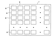
本実施形態における露光装置1は、第1実施形態とは、露光部に関する部分が異なり、これ以外の対応する構成要素には同一の符号を付してその説明を省略する。図5は、本実施形態の露光装置における露光部を示す模式平面図である。
Hereinafter, a third embodiment of an exposure apparatus and an exposure method according to the present invention will be described with reference to the drawings.
The
本実施形態における露光部200は、第1実施形態の露光部20,30,40,50に対応し、照射光学系226下にアライメントステージを有するものとされる。
この露光部200は、図5に示すように、搬送部227がロード用ロボットハンド227aおよびアンロード用ロボットハンド227bを有するものとされる。露光部200は、ストッカー227cの未処理基板をロード用ロボットハンド227aによって照射光学系226下の所定位置にロードして、レディ信号がONとする。また、露光部200は、後処理200EをONとして露光処理を終了した後、アンロード用ロボットハンド227bによって照射光学系226下の処理済基板をストッカー227dにアンロードする。
本実施形態では、露光部200において、第1実施形態のように基板Wを順次露光処理することができる。
The
In the
In the present embodiment, the
さらに、本実施形態では、露光部200において、複数の基板Wを同一工程で露光処理することもできる。
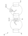
この場合、 図6に示すように、トレイTに載置された複数の基板Wを送部227にて搬送することや、図6に示すトレイTに載置した状態のように、複数の基板Wを照射光学系226下のアライメントステージ上の所定位置に整列して載置し、一括して露光処理することができる。
これにより、本実施形態においては、処理時間を短縮し、より多くの基板Wに対して露光処理をおこなうことができ、生産性をさらに向上することができる。
Further, in the present embodiment, the
In this case, as shown in FIG. 6, the plurality of substrates W placed on the tray T are transported by the sending
Thereby, in the present embodiment, the processing time can be shortened, the exposure processing can be performed on more substrates W, and the productivity can be further improved.
1…露光装置
C…制御部
20,30,40,50…露光部
M…マスク
21…マスクステージ(マスク保持部)
W…ガラス基板(ワーク)
22…ワークステージ(ワーク保持部)
23…ワークステージ移動機構(駆動部)
24…アライメントカメラ
25…レディ信号出力手段
26…照射光学系
27…搬送系
DESCRIPTION OF
W ... Glass substrate (workpiece)
22 ... Work stage (work holding part)
23. Work stage moving mechanism (drive unit)
24 ...
Claims (8)
前記制御部が、前記レディ信号を出力している前記露光部のうち1つの露光部を選択してアライメント開始信号を出力する工程と、
この選択された露光部において、前記両アライメントマークのずれ量が露光転写時の所望のアライメント精度範囲以内となるよう前記駆動部によるアライメント動作を実行する工程とを有することを特徴とする露光方法。 A mask holding unit that holds a mask having a pattern to be exposed; a work holding unit that holds a work as an exposed material; a drive unit that relatively drives the mask holding unit and the work holding unit; A mask-side alignment mark formed on the mask, an alignment camera capable of detecting the workpiece-side alignment mark formed on the workpiece, and a ready signal output means for outputting that alignment can be started. There are provided a plurality of exposure sections that expose and transfer the mask pattern, and the plurality of exposure sections respectively drive and control the drive section based on the displacement amount of the alignment marks detected by the alignment camera. Exposure method in an exposure apparatus provided with a common control unit for executing There is,
The control unit selects one exposure unit from among the exposure units outputting the ready signal and outputs an alignment start signal;
And a step of performing an alignment operation by the driving unit so that a deviation amount between the alignment marks is within a desired alignment accuracy range during exposure transfer in the selected exposure unit.
被露光材としてのワークを保持するワーク保持部と、
前記マスク保持部と前記ワーク保持部とを相対的に駆動する駆動部と、
前記マスクに形成されたマスク側アライメントマーク及び前記ワークに形成されたワーク側アライメントマークを検出可能なアライメントカメラと、
アライメント開始可能であることを出力するレディ信号出力手段と、
を備え前記ワーク上に前記マスクのパターンを露光転写する露光部が複数設けられ、
これら複数の露光部において、それぞれ前記アライメントカメラによって検出された前記両アライメントマークのずれ量に基づいて、前記駆動部を駆動制御してアライメント動作を実行するための制御部が共通して設けられた露光装置であって、
前記制御部が、前記レディ信号を出力している前記露光部のうち1つの露光部を選択してアライメント開始信号を出力することで、
この選択された露光部において、前記両アライメントマークのずれ量が露光転写時の所望のアライメント精度範囲以内となるよう前記駆動部によるアライメント動作を実行することを特徴とする露光装置。 A mask holding unit for holding a mask having a pattern to be exposed;
A work holding unit for holding a work as an exposed material;
A drive unit that relatively drives the mask holding unit and the work holding unit;
An alignment camera capable of detecting a mask side alignment mark formed on the mask and a work side alignment mark formed on the workpiece;
Ready signal output means for outputting that alignment can be started;
A plurality of exposure portions for exposing and transferring the pattern of the mask on the workpiece.
In each of the plurality of exposure units, a common control unit is provided for controlling the driving unit to execute an alignment operation based on the shift amount of the alignment marks detected by the alignment camera. An exposure apparatus,
The control unit selects one of the exposure units that are outputting the ready signal and outputs an alignment start signal,
An exposure apparatus that performs an alignment operation by the driving unit so that a shift amount between the alignment marks is within a desired alignment accuracy range during exposure transfer in the selected exposure unit.
Priority Applications (1)
| Application Number | Priority Date | Filing Date | Title |
|---|---|---|---|
| JP2012164879A JP2014026041A (en) | 2012-07-25 | 2012-07-25 | Exposure device and exposure method |
Applications Claiming Priority (1)
| Application Number | Priority Date | Filing Date | Title |
|---|---|---|---|
| JP2012164879A JP2014026041A (en) | 2012-07-25 | 2012-07-25 | Exposure device and exposure method |
Publications (1)
| Publication Number | Publication Date |
|---|---|
| JP2014026041A true JP2014026041A (en) | 2014-02-06 |
Family
ID=50199749
Family Applications (1)
| Application Number | Title | Priority Date | Filing Date |
|---|---|---|---|
| JP2012164879A Pending JP2014026041A (en) | 2012-07-25 | 2012-07-25 | Exposure device and exposure method |
Country Status (1)
| Country | Link |
|---|---|
| JP (1) | JP2014026041A (en) |
Cited By (1)
| Publication number | Priority date | Publication date | Assignee | Title |
|---|---|---|---|---|
| JP2014085649A (en) * | 2012-10-26 | 2014-05-12 | Ulvac Japan Ltd | Exposure apparatus |
Citations (9)
| Publication number | Priority date | Publication date | Assignee | Title |
|---|---|---|---|---|
| JPH09274582A (en) * | 1996-04-03 | 1997-10-21 | Nikon Corp | Exposure system |
| JPH1140469A (en) * | 1997-07-16 | 1999-02-12 | Nikon Corp | Lithography system and method of control work thereof |
| JP2000036451A (en) * | 1998-07-17 | 2000-02-02 | Nikon Corp | Exposure method and lithography system |
| JP2002359174A (en) * | 2001-05-31 | 2002-12-13 | Mitsubishi Electric Corp | Exposure process managing system, method therefor and program for managing exposure process |
| JP2003022962A (en) * | 2001-07-10 | 2003-01-24 | Canon Inc | Exposing system, method for fabricating device, factory for producing semiconductor and method for maintaining aligner |
| JP2006108474A (en) * | 2004-10-07 | 2006-04-20 | Canon Inc | Exposure device and display manufacturing method using the same |
| WO2007049704A1 (en) * | 2005-10-28 | 2007-05-03 | Nikon Corporation | Device manufacturing apparatus connecting apparatus and connecting method, program, device manufacturing system, exposing apparatus, exposing method, determining/testing apparatus and determining/testing method |
| JP2007173336A (en) * | 2005-12-20 | 2007-07-05 | Nikon Corp | Function supply method, exposure method, exposure apparatus, measuring/inspection method, measuring/inspection apparatus, function supply system, program, recording medium, and providing condition determining method |
| JP2011164590A (en) * | 2010-01-14 | 2011-08-25 | Nsk Ltd | Exposing device and exposure method |
-
2012
- 2012-07-25 JP JP2012164879A patent/JP2014026041A/en active Pending
Patent Citations (9)
| Publication number | Priority date | Publication date | Assignee | Title |
|---|---|---|---|---|
| JPH09274582A (en) * | 1996-04-03 | 1997-10-21 | Nikon Corp | Exposure system |
| JPH1140469A (en) * | 1997-07-16 | 1999-02-12 | Nikon Corp | Lithography system and method of control work thereof |
| JP2000036451A (en) * | 1998-07-17 | 2000-02-02 | Nikon Corp | Exposure method and lithography system |
| JP2002359174A (en) * | 2001-05-31 | 2002-12-13 | Mitsubishi Electric Corp | Exposure process managing system, method therefor and program for managing exposure process |
| JP2003022962A (en) * | 2001-07-10 | 2003-01-24 | Canon Inc | Exposing system, method for fabricating device, factory for producing semiconductor and method for maintaining aligner |
| JP2006108474A (en) * | 2004-10-07 | 2006-04-20 | Canon Inc | Exposure device and display manufacturing method using the same |
| WO2007049704A1 (en) * | 2005-10-28 | 2007-05-03 | Nikon Corporation | Device manufacturing apparatus connecting apparatus and connecting method, program, device manufacturing system, exposing apparatus, exposing method, determining/testing apparatus and determining/testing method |
| JP2007173336A (en) * | 2005-12-20 | 2007-07-05 | Nikon Corp | Function supply method, exposure method, exposure apparatus, measuring/inspection method, measuring/inspection apparatus, function supply system, program, recording medium, and providing condition determining method |
| JP2011164590A (en) * | 2010-01-14 | 2011-08-25 | Nsk Ltd | Exposing device and exposure method |
Cited By (1)
| Publication number | Priority date | Publication date | Assignee | Title |
|---|---|---|---|---|
| JP2014085649A (en) * | 2012-10-26 | 2014-05-12 | Ulvac Japan Ltd | Exposure apparatus |
Similar Documents
| Publication | Publication Date | Title |
|---|---|---|
| US9766503B2 (en) | Polarized light irradiating apparatus and method of irradiating polarized light for photo alignment | |
| US8223319B2 (en) | Exposure device | |
| TW201718159A (en) | Laser processing apparatus | |
| KR101384440B1 (en) | Article loading/unloading method and article loading/unloading device, exposure method and exposure apparatus, and method of manufacturing device | |
| WO2016134654A1 (en) | Mask transmission device and transmission method | |
| JP4158514B2 (en) | Double-sided projection exposure system | |
| KR100523350B1 (en) | Back side Mask Aligner and Exposure | |
| JP5945211B2 (en) | Exposure equipment | |
| JP2007293376A (en) | Exposure device and method for manufacturing substrate | |
| JP4312247B2 (en) | Proximity exposure apparatus and substrate manufacturing method | |
| JP4020261B2 (en) | Exposure method, exposure apparatus, and substrate manufacturing method | |
| JP2014026041A (en) | Exposure device and exposure method | |
| WO2015107855A1 (en) | Normal temperature bonding device | |
| JP4312248B2 (en) | Proximity exposure apparatus and substrate manufacturing method | |
| JP2009194147A (en) | Wafer exposure apparatus and wafer exposure method | |
| JP2010034427A (en) | Treatment device and method of manufacturing device | |
| JP2005086093A (en) | Aligner and method of controlling stage apparatus | |
| JPH06291017A (en) | Semiconductor manufacturing device | |
| JPH0774084A (en) | Substrate processor | |
| US20100182586A1 (en) | Lithography apparatus, and method of manufacturing device using same | |
| JP5799304B2 (en) | Exposure unit and exposure method using the same | |
| KR20110053903A (en) | Exposure apparatus and method of manufacturing device | |
| CN112835271B (en) | Exposure method for lithographic apparatus with rotary exchange double workpiece stage | |
| JP7216568B2 (en) | Conveying device, exposure device, and article manufacturing method | |
| TW202309681A (en) | Multiple camera apparatus for photolithographic processing |
Legal Events
| Date | Code | Title | Description |
|---|---|---|---|
| A621 | Written request for application examination |
Free format text: JAPANESE INTERMEDIATE CODE: A621 Effective date: 20150423 |
|
| A977 | Report on retrieval |
Free format text: JAPANESE INTERMEDIATE CODE: A971007 Effective date: 20160226 |
|
| A131 | Notification of reasons for refusal |
Free format text: JAPANESE INTERMEDIATE CODE: A131 Effective date: 20160308 |
|
| A02 | Decision of refusal |
Free format text: JAPANESE INTERMEDIATE CODE: A02 Effective date: 20160913 |