JP2014023611A - Radiographic apparatus, control method, and program - Google Patents
Radiographic apparatus, control method, and program Download PDFInfo
- Publication number
- JP2014023611A JP2014023611A JP2012164740A JP2012164740A JP2014023611A JP 2014023611 A JP2014023611 A JP 2014023611A JP 2012164740 A JP2012164740 A JP 2012164740A JP 2012164740 A JP2012164740 A JP 2012164740A JP 2014023611 A JP2014023611 A JP 2014023611A
- Authority
- JP
- Japan
- Prior art keywords
- radiation
- irradiation
- subject
- size
- detecting
- Prior art date
- Legal status (The legal status is an assumption and is not a legal conclusion. Google has not performed a legal analysis and makes no representation as to the accuracy of the status listed.)
- Withdrawn
Links
- 238000000034 method Methods 0.000 title claims description 8
- 230000005855 radiation Effects 0.000 claims abstract description 129
- 238000001514 detection method Methods 0.000 claims abstract description 74
- 238000003384 imaging method Methods 0.000 claims description 78
- 230000001678 irradiating effect Effects 0.000 claims description 5
- 238000012545 processing Methods 0.000 description 9
- 238000002594 fluoroscopy Methods 0.000 description 6
- 230000008859 change Effects 0.000 description 5
- 230000006870 function Effects 0.000 description 5
- 230000008569 process Effects 0.000 description 5
- 238000006243 chemical reaction Methods 0.000 description 4
- 230000007246 mechanism Effects 0.000 description 4
- 239000000758 substrate Substances 0.000 description 4
- 238000010586 diagram Methods 0.000 description 3
- OAICVXFJPJFONN-UHFFFAOYSA-N Phosphorus Chemical compound [P] OAICVXFJPJFONN-UHFFFAOYSA-N 0.000 description 2
- 238000004891 communication Methods 0.000 description 2
- 238000012790 confirmation Methods 0.000 description 2
- 238000003745 diagnosis Methods 0.000 description 2
- 229910052751 metal Inorganic materials 0.000 description 2
- 239000002184 metal Substances 0.000 description 2
- 238000002601 radiography Methods 0.000 description 2
- 201000010099 disease Diseases 0.000 description 1
- 208000037265 diseases, disorders, signs and symptoms Diseases 0.000 description 1
- 210000001035 gastrointestinal tract Anatomy 0.000 description 1
- 239000011521 glass Substances 0.000 description 1
- 229910001385 heavy metal Inorganic materials 0.000 description 1
- 239000000463 material Substances 0.000 description 1
- 230000035699 permeability Effects 0.000 description 1
- 238000011160 research Methods 0.000 description 1
- 239000011347 resin Substances 0.000 description 1
- 229920005989 resin Polymers 0.000 description 1
- 238000012546 transfer Methods 0.000 description 1
- 230000009466 transformation Effects 0.000 description 1
Images


Classifications
-
- A—HUMAN NECESSITIES
- A61—MEDICAL OR VETERINARY SCIENCE; HYGIENE
- A61B—DIAGNOSIS; SURGERY; IDENTIFICATION
- A61B6/00—Apparatus for radiation diagnosis, e.g. combined with radiation therapy equipment
- A61B6/10—Application or adaptation of safety means
- A61B6/107—Protection against radiation, e.g. shielding
-
- A—HUMAN NECESSITIES
- A61—MEDICAL OR VETERINARY SCIENCE; HYGIENE
- A61B—DIAGNOSIS; SURGERY; IDENTIFICATION
- A61B6/00—Apparatus for radiation diagnosis, e.g. combined with radiation therapy equipment
- A61B6/44—Constructional features of apparatus for radiation diagnosis
- A61B6/4429—Constructional features of apparatus for radiation diagnosis related to the mounting of source units and detector units
- A61B6/4435—Constructional features of apparatus for radiation diagnosis related to the mounting of source units and detector units the source unit and the detector unit being coupled by a rigid structure
- A61B6/4441—Constructional features of apparatus for radiation diagnosis related to the mounting of source units and detector units the source unit and the detector unit being coupled by a rigid structure the rigid structure being a C-arm or U-arm
-
- A—HUMAN NECESSITIES
- A61—MEDICAL OR VETERINARY SCIENCE; HYGIENE
- A61B—DIAGNOSIS; SURGERY; IDENTIFICATION
- A61B6/00—Apparatus for radiation diagnosis, e.g. combined with radiation therapy equipment
- A61B6/46—Apparatus for radiation diagnosis, e.g. combined with radiation therapy equipment with special arrangements for interfacing with the operator or the patient
- A61B6/461—Displaying means of special interest
-
- A—HUMAN NECESSITIES
- A61—MEDICAL OR VETERINARY SCIENCE; HYGIENE
- A61B—DIAGNOSIS; SURGERY; IDENTIFICATION
- A61B6/00—Apparatus for radiation diagnosis, e.g. combined with radiation therapy equipment
- A61B6/54—Control of apparatus or devices for radiation diagnosis
-
- A—HUMAN NECESSITIES
- A61—MEDICAL OR VETERINARY SCIENCE; HYGIENE
- A61B—DIAGNOSIS; SURGERY; IDENTIFICATION
- A61B6/00—Apparatus for radiation diagnosis, e.g. combined with radiation therapy equipment
- A61B6/06—Diaphragms
-
- A—HUMAN NECESSITIES
- A61—MEDICAL OR VETERINARY SCIENCE; HYGIENE
- A61B—DIAGNOSIS; SURGERY; IDENTIFICATION
- A61B6/00—Apparatus for radiation diagnosis, e.g. combined with radiation therapy equipment
- A61B6/46—Apparatus for radiation diagnosis, e.g. combined with radiation therapy equipment with special arrangements for interfacing with the operator or the patient
- A61B6/467—Apparatus for radiation diagnosis, e.g. combined with radiation therapy equipment with special arrangements for interfacing with the operator or the patient characterised by special input means
- A61B6/469—Apparatus for radiation diagnosis, e.g. combined with radiation therapy equipment with special arrangements for interfacing with the operator or the patient characterised by special input means for selecting a region of interest [ROI]
-
- A—HUMAN NECESSITIES
- A61—MEDICAL OR VETERINARY SCIENCE; HYGIENE
- A61B—DIAGNOSIS; SURGERY; IDENTIFICATION
- A61B6/00—Apparatus for radiation diagnosis, e.g. combined with radiation therapy equipment
- A61B6/54—Control of apparatus or devices for radiation diagnosis
- A61B6/547—Control of apparatus or devices for radiation diagnosis involving tracking of position of the device or parts of the device
Abstract
Description
本発明は、放射線撮影装置、制御方法およびプログラムに関するものである。 The present invention relates to a radiation imaging apparatus, a control method, and a program.
被写体を透過した放射線(例えば、X線)の検出に基づいて放射線画像を撮影する放射線撮影装置が知られている。放射線撮影装置は、例えば、放射線により消化管等の撮影部位を撮影する。また、放射線撮影装置は、病気治療時の検査のみならず、定期健診等にも広く使用されている。
放射線撮影装置には種々の形態がある。例えば、特許文献1および2では、Cアームと呼ばれる支持部材の両端に取り付けられたX線発生装置とX線検出装置との間に、寝台の天板に載せた被写体を位置させ、当該被写体を透視および撮影する装置がある。X線発生装置から照射されたX線は被写体を透過してX線検出装置に入射する。この被写体を透過したX線は、X線検出装置において、電気信号に変換される。このような動作を所定のX線照射条件で実施することにより、被写体の透視および撮影画像をリアルタイムにモニタに表示させることができる。
A radiation imaging apparatus that captures a radiation image based on detection of radiation (for example, X-rays) that has passed through a subject is known. For example, the radiation imaging apparatus images an imaging region such as a digestive tract with radiation. In addition, the radiographic apparatus is widely used not only for examination at the time of disease treatment but also for regular medical examinations.
There are various types of radiation imaging apparatuses. For example, in
上述したX線撮影装置の場合、オペレータが行う透視および撮影に係わる操作ステップとして、1)透視しながら行う位置決め、2)透視状態における診断(撮影部位の確認)、3)位置決めした部位の撮影、に大きく分類される。
このうち、1)の「透視しながら行う位置決め」では、撮影部位がモニタの適切な位置(例えば、中央の位置)に所望サイズで表示されるように位置決めを行う。位置決めでは、オペレータは、X線発生装置、X線検出装置、天板の少なくとも何れかを移動させる。つまり、位置決め中、オペレータがこれらを移動させているため、モニタに表示される画像(観察画像)は動いていることになる。
これに対して、2)の「透視状態における診断(撮影部位の確認)」では、オペレータによる位置決め操作は行われておらず、モニタの観察画像の位置は固定した状態にある。その後、オペレータが目視で撮影部位を確認すると、所定のX線照射条件により、3)の「撮影」が実施される。X線撮影に際しては、これら1)〜3)の操作ステップが繰り返される。
In the case of the above-described X-ray imaging apparatus, as operation steps relating to fluoroscopy and radiographing performed by an operator, 1) positioning performed while fluoroscopically performed, 2) diagnosis in fluoroscopic state (confirmation of radiographic region), 3) radiography of the positioned region, Is broadly classified.
Among these, in 1) “positioning while seeing through”, positioning is performed so that the imaging region is displayed in a desired size at an appropriate position (for example, the center position) of the monitor. In positioning, the operator moves at least one of the X-ray generator, the X-ray detector, and the top board. That is, since the operator moves these during positioning, the image (observation image) displayed on the monitor is moving.
On the other hand, in 2) “diagnosis in fluoroscopic state (confirmation of imaging region)”, the positioning operation by the operator is not performed, and the position of the observation image on the monitor is fixed. Thereafter, when the operator visually confirms the imaging region, “imaging” of 3) is performed under predetermined X-ray irradiation conditions. In the X-ray imaging, the operation steps 1) to 3) are repeated.
一般に、X線を使用する医用モダリティにおいては、透視および撮影に要する時間や、被写体のX線被爆量をいかに低減させるかということが、重要な管理項目および研究項目になっている。
例えば、上述した「透視しながら行う位置決め」では、モニタに表示される画像がオペレータの位置決め操作のみに連動してモニタ上を移動すれば、透視することなく位置決め操作の継続が可能となり、被写体のX線被爆量を低減できる。
In general, in medical modalities that use X-rays, the time required for fluoroscopy and imaging and how to reduce the amount of X-ray exposure of an object are important management items and research items.
For example, in the above-described “positioning performed while seeing through”, if the image displayed on the monitor moves on the monitor in conjunction with only the positioning operation of the operator, the positioning operation can be continued without seeing through the subject. X-ray exposure can be reduced.
本発明は、上記問題点に鑑みてなされたものであり、位置決め操作時における操作性を向上させると共に、撮影部位の位置決め操作に必要な放射線の照射や撮影を必要十分なタイミングにすることにより、被写体の放射線被爆量を低減することを目的とする。 The present invention has been made in view of the above problems, and improves operability at the time of positioning operation, and at the necessary and sufficient timing of radiation irradiation and imaging necessary for positioning operation of the imaging region, The object is to reduce the radiation exposure of the subject.
本発明は、放射線を被写体に向けて照射する放射線発生手段と、前記被写体を透過した放射線を検出する放射線検出手段と、前記放射線発生手段により照射される放射線の照射範囲のサイズを検出する照射サイズ検出手段と、前記被写体に対する前記放射線発生手段および前記放射線検出手段の相対的な移動を検出する移動検出手段と、前記放射線発生手段による前記被写体に向けた放射線の照射を制御する制御手段と、を有し、前記制御手段は、前記放射線の照射の停止後、前記移動検出手段により検出された相対的な移動量および前記照射サイズ検出手段により検出される照射範囲のサイズに応じて前記放射線発生手段による前記被写体に向けた放射線の照射を再開することを特徴とする。 The present invention relates to a radiation generating means for irradiating radiation toward a subject, a radiation detecting means for detecting radiation transmitted through the subject, and an irradiation size for detecting a size of a radiation range irradiated by the radiation generating means. Detection means; movement detection means for detecting relative movement of the radiation generation means and the radiation detection means with respect to the subject; and control means for controlling irradiation of the radiation toward the subject by the radiation generation means. And the control means includes the radiation generating means according to a relative movement amount detected by the movement detecting means and a size of an irradiation range detected by the irradiation size detecting means after the radiation irradiation is stopped. The irradiation of the radiation toward the subject is resumed.
本発明によれば、位置決め操作時における操作性が向上し、被写体の放射線被爆量を低減できる。 According to the present invention, the operability during the positioning operation is improved, and the radiation exposure amount of the subject can be reduced.
以下、本発明に係る実施形態について図面を参照して詳細に説明する。なお、以下の実施形態では、放射線としてX線を適用した場合を例に挙げて説明するが、X線に限られず、電磁波や、α線、β線、γ線等であってもよい。また、以下の実施形態では、放射線撮影装置として、Cアームを搭載したX線撮影装置を例に挙げて説明する。このX線撮影装置では、X線発生部とX線検出部とを互いに連結して構成した撮影系を移動または回転させながら撮影を行う。なお、本発明はこのようなタイプのX線撮影装置に限られず、例えばRF撮影装置等と呼ばれているテーブル型のX線撮影装置等であってもよい。 Hereinafter, embodiments according to the present invention will be described in detail with reference to the drawings. In the following embodiments, a case where X-rays are applied as radiation will be described as an example. However, the present invention is not limited to X-rays, and may be electromagnetic waves, α rays, β rays, γ rays, or the like. In the following embodiments, an X-ray imaging apparatus equipped with a C-arm will be described as an example of the radiation imaging apparatus. In this X-ray imaging apparatus, imaging is performed while moving or rotating an imaging system configured by connecting an X-ray generation unit and an X-ray detection unit to each other. The present invention is not limited to such a type of X-ray imaging apparatus, and may be a table type X-ray imaging apparatus called an RF imaging apparatus, for example.
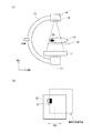
図1は、X線撮影装置10の構成の一例を示す図である。
X線撮影装置10は、単数または複数のコンピュータを含んで構成される。コンピュータは、後述する制御部21として機能し、例えば、CPU、ROM(Read Only Memory)、RAM(Random Access Memory)等を具備する。また、X線撮影装置10は、ネットワークカード等の通信部、キーボード、マウス等の入力部、モニタ等の表示部、タッチパネル等の入出力部等を具備してもよい。なお、これら各構成部は、バス等により接続され、CPUがROMに記憶されたプログラムを実行することで制御される。
FIG. 1 is a diagram illustrating an example of the configuration of the
The
X線撮影装置10は、本体部11と、水平軸12と、Cアーム13とを具備して構成される。水平軸12は、本体部11に支持されており、本体部11に対して移動および回転する。Cアーム13は、水平軸12の先端に設けられ、C字状のアーム部材から構成される。これら水平軸12やCアーム13は、図中矢印に示す方向へ回転(矢印Rc、Rh、Rv)したり、移動(矢印Mh、Mv)したりする。
Cアーム13の両端には、X線発生部14とX線検出部1とが対向して設けられる。Cアーム13は、X線発生部14とX線検出部1との互いの距離を一定に保つようにこれらを支持する。X線発生部14およびX線検出部1は、可動機構(不図示)により被写体15に対して任意の位置および角度で位置決めされる。
The
At both ends of the C-
X線発生部14は、放射線発生部として機能し、被写体(例えば、人体)15に向けて放射線(X線)を照射(曝射)する。X線検出部1は、放射線検出部として機能し、被写体を透過したX線を検出する。被写体15は、被写体支持手段として機能する天板16に支持される。天板16は、X線発生部14とX線検出部1との間に設けられる。仮想軸17は、X線検出部1の有効撮影範囲の中央とX線発生部14とを結ぶX線照射軸である。
ここで、X線発生部14には、絞り部18が設けられる。絞り部18は、X線の量(放射線量)を調整する絞り機構として機能する。この機構によりX線の照射範囲(特に、照射領域のサイズ)が変更される。絞り部18は、X線の量を調整するために遮蔽板(例えば、X線遮蔽率の高い鉛等の重金属等から形成される)を有して構成される。これにより、X線発生部14は、撮影部位に応じて最適な形状でX線を被写体15に照射する。絞り部18は、例えば、二枚の遮蔽板により開口幅を変化させる2組の遮蔽機構を互いに直交して配置する構成(矩形状の構成)であってもよいし、また、円形状や多角形状等の構成であってもよい。更に、X線発生部14には、照射範囲のサイズを検出する照射サイズ検出部19が設けられる。照射サイズ検出部19は、絞り部18の開口幅およびX線発生部14とX線検出部1との距離から、照射範囲のサイズを検出する。
The
Here, the
また、本体部11には、機能的な構成として、例えば、移動検出部20と、制御部21とが設けられる。移動検出部20は、水平軸12の移動や回転に関する情報(例えば、移動方向、移動量、移動速度)を検出する。すなわち、移動検出部20は、Mh方向およびMv方向への水平軸12の移動や、Rv方向への水平軸12の回転を検出する。移動検出部20としては、例えば、リニアエンコーダを用いることができる。制御部21は、絞り部18の動作(絞り)制御、撮影された放射線画像のモニタ(不図示)への表示制御を含めたX線撮影装置10の制御や撮影された放射線画像の記憶等を行う。
このようなX線撮影装置10において、オペレータは、モニタに表示された放射線画像を観察しながら、被写体15の所望撮影部位31が撮影できるように位置決め操作を行う。
The
In such an
次に、本実施形態の位置決め操作時における撮影制御処理について、図2〜図4を参照して説明する。図2(a)、図3(a)、図4(a)はCアームと所望撮影部位との位置関係を示す図である。図2(b)、図3(b)、図4(b)は、それぞれ図2(a)、図3(a)、図4(a)に対応するモニタの表示を示す図である。
ここでは、被写体15の所望撮影部位31と、X線撮影装置10とが図2(a)に示す位置関係で透視されているとする。この場合、所望撮影部位31の右側部分のみにX線が照射されているので、図2(b)に示すように、モニタには全体画像32の中の所望撮影部位31の右側部分(黒色部)のみが表示される。所望撮影部位31の左側部分(ハッチング部)は、X線が照射されていないので、モニタに表示されない。所望撮影部位31の全体を観察する為に、所望撮影部位31をX線の照射範囲の中央付近へ移動する場合、オペレータは、Cアーム13をMh方向(より詳細には、被写体15から遠ざかる向き)に移動させる操作を行う。これにより、制御部21はX線発生部14およびX線検出部1を被写体15に対して相対的に移動させる。制御部21は、Cアーム13の移動を開始させるとX線の照射を停止し、X線の照射の停止直前に撮影された最終放射線画像を制御部21内の例えばRAMに記憶すると同時にモニタに表示する。制御部21はオペレータの操作に応じてCアーム13を継続して移動させている場合、最終放射線画像がモニタ上をシフトするように継続して表示する。制御部21は最終放射線画像のモニタ上のシフト方向およびシフト量を、移動検出部20の検出結果に連動して決定する。すなわち、本実施形態では、制御部21はCアーム13の移動中、図3(a)に示すようなCアーム13の移動方向および移動量に対応して、図3(b)に示すように最終放射線画像(点線部)を右方向へ移動させながらモニタに表示する。
Next, the imaging control process during the positioning operation of the present embodiment will be described with reference to FIGS. 2 (a), 3 (a), and 4 (a) are diagrams showing the positional relationship between the C-arm and the desired imaging region. FIGS. 2B, 3B, and 4B are diagrams showing the display on the monitor corresponding to FIGS. 2A, 3A, and 4A, respectively.
Here, it is assumed that the desired
一方、位置決めを継続する為に、Cアーム13がX線の照射範囲以上を移動し、最終放射線画像がモニタに全く表示されない状態になる前にX線の照射を再開する必要がある。すなわち、本実施形態では、制御部21は、Cアーム13の移動方向および移動量が、最終放射線画像のX線の照射範囲と所定関係になった時点でX線の照射を再開し、その放射線画像をモニタに表示する。図4に示す例では、制御部21は、図4(a)に示すようにCアーム13を最終放射線画像のX線の照射範囲のおおよそ半分の距離だけ移動した時点で照射を再開するように制御している。したがって、制御部21は、図4(a)の状態で所望撮影部位31の全体にX線を照射し、図4(b)に示すようにその放射線画像をモニタに表示する。
On the other hand, in order to continue positioning, it is necessary to resume the X-ray irradiation before the C-
次に、図1に示すX線検出部1の内部の断面構成の一例について図5を参照して説明する。
検出パネル2は、被写体を透過したX線を検出するパネルである。検出パネル2は、蛍光板2aと、光電変換素子2bと、基板2cとを具備して構成される。基板2cには、例えば、ガラス板を用いることができる。基板2c上に光電変換素子2bが2次元状(または1次元状)に配列される。検出パネル2の端部には、光電変換された電気信号を読み出す読出回路や、読出対象となる素子を選択するための駆動回路等が接続される。検出パネル2は、例えば、矩形形状であり、読出回路と駆動回路とは、互いに直交する辺にそれぞれ配置される。
Next, an example of a cross-sectional configuration inside the X-ray detection unit 1 shown in FIG. 1 will be described with reference to FIG.
The
蛍光板2aには、例えば、金属化合物の蛍光体を樹脂板に塗布したものが用いられる。蛍光板2aは、基板2cと一体化されて形成され、検出パネル2として金属製の基台3に固定される。基台3の裏側には、電気基板4が配置される。電気基板4は、検出パネル2から得られる電気信号に基づいてX線画像(放射線画像)を生成する。なお、電気基板4は、フレキシブル回路基板5を介して検出パネル2と接続されている。
As the
基台3は、筐体6aに固定される。X線検出部1は、この筐体6aと、X線透過性の高い材料から成る筐体蓋6bとによって密閉されて構成される。X線検出部1は、ケーブル7および中継用電気回路部8を介して、制御部21に接続される。これにより、X線検出部1は、電源供給や信号転送等を行う。
X線検出部1は、上述した通り、被写体を透過したX線に基づいて放射線画像の撮影を行う。被写体を透過したX線がX線検出部1に入射されると、蛍光板2aの蛍光体が発光し、2次元配列された光電変換素子2bがその光を電気信号に変換する。そして、ケーブル7を介して電気的な画像情報として制御部21に転送される。制御部21がモニタに画像情報を表示することで、オペレータはリアルタイムで放射線画像を観察できる。
The base 3 is fixed to the
As described above, the X-ray detection unit 1 captures a radiographic image based on X-rays transmitted through the subject. When X-rays that have passed through the subject are incident on the X-ray detector 1, the phosphor of the
次に、X線撮影装置10における撮影動作の一例について図6に示すフローチャートを参照して説明する。
オペレータにより(または自動的に)透視の開始が指示された場合、X線撮影装置10の制御部21は、被写体15の透視を開始する(S101)。具体的には、X線発生部14において、X線被写体(例えば、人体)に向けてX線を照射し、X線検出部1において、被写体を透過したX線に基づく放射線画像を連続して撮影する。制御部21は、図2(b)に示すように、所定の照射範囲の放射線画像をリアルタイムでモニタに表示する(S102)。
Next, an example of an imaging operation in the
When the start of fluoroscopy is instructed by the operator (or automatically), the
次に、制御部21は、オペレータにより(または自動的に)撮影の終了が指示されたか否かを判定する(S103)。撮影の終了が指示された場合(S103でYES)、制御部21は、撮影処理を終了する。撮影の終了が指示されていない場合(S103でNO)、制御部21は、この撮影中におけるCアーム13の移動を継続的に監視する。具体的には、制御部21は、移動検出部20から水平軸12の移動や回転に関する情報を検出し、Cアーム13が移動したか否かを判定する(S104)。移動検出部20による検出結果に変化がない場合には、制御部21はCアーム13が移動していないと判定し(S104でNO)、現状のX線の照射および放射線画像のリアルタイム表示状態を維持する(S101、S102)。一方、検出結果に変化がある場合には、制御部21はCアーム13が移動していると判定し(S104でYES)、X線の照射を停止すると共に(S105)、最終放射線画像を制御部21内のRAM等に記憶する(S106)。この処理は、記憶手段による処理の一例に対応する。ここで、最終放射線画像は、X線の照射を停止するとき(停止直前)に撮影された放射線画像である。
Next, the
そして、制御部21はCアーム13の移動(すなわち、移動検出部20の検出結果)に応じて最終放射線画像をモニタに連続してシフトさせながら表示する(S107)。例えば、図3(a)に示すようにMh方向において被写体15から遠ざかる向き(すなわち、左側)にCアーム13を移動させている場合には、制御部21は、図3(b)に示すように、最終放射線画像がモニタ上を右方向へシフトするように表示する。図3に示すように、Cアーム13の移動距離がLであれば、モニタに表示される最終放射線画像が距離Lに相当する量だけ変化する。ここでは、距離LはX線の照射範囲のMh方向のサイズのおおよそ1/4である。
このようにして、制御部21は、所望撮影部位31にX線を照射することなく、所望撮影部位31とX線の照射範囲との相対位置関係をモニタに表示する。制御部21は、Cアーム13の移動に応じて継続して最終放射線画像を表示する。例えば、Cアーム13の移動方向がこれまでと逆方向に変われば、制御部21は、右方向へ移動していた最終放射線画像を左方向へ移動する。
Then, the
In this way, the
S107に続いて、制御部21は、Cアーム13の移動量が所定値になったか否かを判定する。Cアーム13の移動量が所定値になったことを検出した場合(S108でYES)、制御部21は、S101の処理に戻り、図4(a)、(b)に示すように、X線の照射を再開する。なお、その後、Cアーム13が停止した場合(S104でYES)であっても、S101に戻り、制御部21はX線の照射を継続する。
一方、S108において、Cアーム13の移動量が所定値になっていない場合(S108でNO)、制御部21は、S103の処理に戻る。そして、撮影が終了するまで上述した処理を繰り返し行う。
Subsequent to S107, the
On the other hand, in S108, when the movement amount of the C-
本実施形態では、Cアーム13の移動量が、最終放射線画像の撮影時のX線の照射範囲のサイズの1/2、すなわち所望撮影部位31がX線の照射範囲の中央部に位置することにより照射を再開するように制御される。したがって、図4(a)、(b)において、モニタの中央部に表示されている所望撮影部位31は、X線の照射が再開されることで撮影された放射線画像である。なお、最終放射線画像の撮影時のX線の照射範囲のサイズは、照射サイズ検出部19の検出結果に基づいている。
In the present embodiment, the movement amount of the C-
また、本実施形態におけるX線の照射が再開されるCアーム13の移動量は一例であり、撮影目的に応じて、X線の照射範囲のサイズに基づき任意に設定することができる。
例えば、X線撮影装置10では、オペレータが照射範囲のサイズの「1/3」の移動量で照射を再開させることを入力部を介して制御部21に入力(選択を含む)するように構成することができる。ここでは、「1/3」を照射再開サイズ割合という。この場合、制御部21は、照射サイズ検出部19から最終放射線画像の照射範囲のサイズを取得し、取得した照射範囲のサイズの例えば一辺の距離に、入力された照射再開サイズ割合(「1/3」)を乗算した距離を算出する。制御部21は、算出した距離を、照射を再開するか否かを判定するための所定値として設定することができる。
Further, the amount of movement of the
For example, the
また、オペレータが照射再開サイズ割合を入力する場合等に限られず、被爆量の大〜小を段階的または連続的に入力(選択を含む)できるように構成してもよい。この場合、被爆量「小」には照射範囲のサイズの例えば「1/2」の移動量で照射を再開させることを関連付け、被爆量「大」には照射範囲のサイズの例えば「1/4」の移動量で照射を再開させることを関連付けて、記憶されたテーブルがROM等に予め記憶されている。制御部21は、入力された被爆量の大〜小からテーブルを参照することで照射を再開する照射再開サイズ割合(「1/2」、「1/4」等)を取得する。制御部21は、取得した照射再開サイズ割合を用いて上述と同様の処理をすることで、照射を再開するか否かを判定するための所定値を設定することができる。
Moreover, it is not restricted to the case where an operator inputs the irradiation resumption size ratio etc., You may comprise so that the magnitude | size of exposure amount may be input in steps or continuously (a selection is included). In this case, the exposure amount “small” is associated with resuming the irradiation with a movement amount of, for example, “½” of the irradiation range size, and the exposure amount “large” is, for example, “1/4” of the irradiation range size. The stored table is stored in advance in a ROM or the like in association with the resumption of irradiation with the movement amount of “”. The
また、例えばオペレータが「撮影目的(撮影部位を含む)」等を入力部を介して制御部21に入力(選択を含む)するように構成してもよい。この場合、「撮影目的」と、照射を再開する照射再開サイズ割合(「1/2」、「1/4」等)とを関連付けて、記憶されたテーブルがROM等に予め記憶されている。制御部21は、入力された「撮影目的」からテーブルを参照することで照射を再開する照射再開サイズ割合(「1/2」、「1/4」等)を取得する。制御部21は、取得した照射再開サイズ割合を用いて上述と同様の処理をすることで、照射を再開するか否かを判定するための所定値を設定することができる。
Further, for example, the operator may input (including selection) “imaging purpose (including imaging region)” or the like to the
以上、本実施形態によれば、オペレータによる位置決め操作に応じてX線を照射する期間が自動的に決定される。より詳細には、制御部21は、X線の照射範囲のサイズと、被写体に対するX線発生部14およびX線検出部1の相対的な位置情報(移動量)とに基づいてX線の照射有無を制御する。これにより自動で照射タイミングが制御されるので位置決め操作時における操作性が向上し、被写体のX線被爆量を低減できる。
また、本実施形態では、放射線の照射を停止された状態から、被写体に対するX線発生部14およびX線検出部1の相対的な移動量に加えて、照射サイズ検出部19により検出される照射範囲のサイズに応じて放射線の照射を再開するか否かを判定している。すなわち、制御部21は、例えば相対的な移動量が同じでも、照射範囲のサイズが大きい場合には放射線の照射は再開せず、照射範囲のサイズが小さい場合には放射線の照射は再開するように制御することができる。このような制御をすることで、照射範囲のサイズに応じて被写体の被爆量を低減できると共に、照射範囲のサイズに応じて放射線の照射は再開されるのでオペレータは所望する放射線画像を観察することができる。
As described above, according to the present embodiment, the period of X-ray irradiation is automatically determined according to the positioning operation by the operator. More specifically, the
In the present embodiment, in addition to the relative movement amount of the
(第2の実施形態)
次に、第2の実施形態のX線撮影装置10における撮影動作の一例について図7に示すフローチャートを参照して説明する。なお、本実施形態において、第1の実施形態と同一の部材およびフローチャートのステップには同一の記号を付し、当該部材およびステップについては詳細な説明を省略する。ここでは、図7に示すフローチャートのうち、ステップS101からステップS104、ステップS105からステップS108までは、第1の実施形態のフローチャートと同一である。本実施形態では、ステップS104とステップS105の間にステップS201を追加している。
(Second Embodiment)
Next, an example of an imaging operation in the
ステップS201では、制御部21は、Cアーム13の移動速度が所定速度以上か否かを判定する。この判定は、移動検出部20による検出結果に基づいて行う。Cアーム13の移動速度が所定速度以上の場合(S201でYES)、制御部21はX線の照射を停止する(S105)。一方、Cアーム13の移動速度が所定速度よりも小さい場合(S201でNO)、制御部21は、ステップ102へ戻り、現状の照射状態を維持する。そして、撮影が終了するまで上述した処理を繰り返し行う。本実施形態では、移動速度が大きい場合にはラフな位置決め操作を行っていると判断し、放射線画像をリアルタイムで表示する必要性が高くないという考えに基づいている。ここで、X線の照射を停止するか否かを判定するための所定速度は、X線の照射範囲のサイズに基づいて任意に設定すればよい。例えば、制御部21は、照射範囲のサイズが大きい場合やオペレータの操作の熟練度が高い場合には、上述した所定速度を大きくして設定することができる。この処理は設定手段による処理の一例に対応する。このように照射範囲サイズが大きい場合やオペレータの操作の熟練度が高い場合には、所定速度を大きく設定しても、位置決め操作への支障は少ない。
In step S201, the
以上、本実施形態によれば、上述した第1の実施形態と同様、自動で照射タイミングが制御されるので位置決め操作時における操作性が向上し、被写体のX線被爆量を低減できる。また、本実施形態では、被写体に対するX線発生部14およびX線検出部1の相対的な移動があった場合に、その移動速度が所定速度以上の場合にはラフな位置決め操作の段階であるとしてX線の照射を停止させることで、被写体のX線被爆量を低減できる。また、所定速度よりも小さい場合には、オペレータが放射線画像を観察したい段階であるとしてX線の照射を継続させることで、操作性を向上させることができる。
As described above, according to the present embodiment, since the irradiation timing is automatically controlled as in the first embodiment described above, the operability during the positioning operation is improved, and the X-ray exposure amount of the subject can be reduced. In the present embodiment, when the
以上、本発明の好ましい実施形態について説明したが、本発明はこれらの実施形態に限定されないことはいうまでもなく、その要旨の範囲内で種々の変形および変更が可能である。
例えば、上述した実施形態では、Cアーム13のMh方向の移動に応じてX線の照射を行う期間が自動的に決定され、X線を照射しない期間はモニタに表示した最終放射線画像をシフトさせて表示する場合について説明した。しかしながら、これ以外の位置決め操作が行われときにも本発明を適用できる。例えば、Cアーム13のRv方向への回転、複数方向への移動や回転が同時に行われた場合にも、X線の照射を行う期間を自動的に設定するようにしてもよい。具体的には、図8(a)に示すように、Cアーム13が、Mh方向において被写体15から遠ざかる向きへ移動すると共に、紙面の表側へ向かって移動された場合である。この場合、図8(b)に示すように、最終放射線画像はモニタ上を右上方へシフトしながら表示される。
As mentioned above, although preferred embodiment of this invention was described, it cannot be overemphasized that this invention is not limited to these embodiment, A various deformation | transformation and change are possible within the range of the summary.
For example, in the above-described embodiment, the period during which X-ray irradiation is performed is automatically determined according to the movement of the C-
また、上述した実施形態では、被写体15を支持する天板16が固定され、撮影系のみが移動するタイプのX線撮影装置10を例に挙げて説明したが、X線撮影装置は、このタイプの装置に限られない。X線撮影装置は、撮影系と天板との相対的な位置および角度の変化、移動速度を検出する検出部を備えていればよく、例えば、天板のみが移動するタイプのものであってもよいし、撮影系と天板との両方が移動するタイプのものであってもよい。また、撮影系や天板の移動は、手動であっても、電動であっても構わない。
In the above-described embodiment, the
また、上述したX線撮影装置10における処理を、コンピュータにインストールされたプログラムにより実施するように構成してもよい。なお、このプログラムは、ネットワーク等の通信手段により提供することは勿論、CD−ROM等の記録媒体に格納して提供することも可能である。
Moreover, you may comprise so that the process in the
1:X線検出部 10:X線撮影装置(放射線撮影装置) 14:X線発生部 15:被写体 19:照射サイズ検出部 20:移動検出部 21:制御部 31:所望撮影部位 1: X-ray detection unit 10: X-ray imaging apparatus (radiography apparatus) 14: X-ray generation unit 15: Subject 19: Irradiation size detection unit 20: Movement detection unit 21: Control unit 31: Desired imaging region
Claims (9)
前記被写体を透過した放射線を検出する放射線検出手段と、
前記放射線発生手段により照射される放射線の照射範囲のサイズを検出する照射サイズ検出手段と、
前記被写体に対する前記放射線発生手段と前記放射線検出手段との相対的な移動を検出する移動検出手段と、
前記放射線発生手段による前記被写体に向けた放射線の照射を制御する制御手段と、を有し、
前記制御手段は、
前記放射線の照射の停止後、前記移動検出手段により検出された相対的な移動量および前記照射サイズ検出手段により検出される照射範囲のサイズに応じて前記放射線発生手段による前記被写体に向けた放射線の照射を再開することを特徴とする放射線撮影装置。 Radiation generating means for irradiating the subject with radiation,
Radiation detecting means for detecting radiation transmitted through the subject;
An irradiation size detecting means for detecting a size of an irradiation range of radiation irradiated by the radiation generating means;
A movement detecting means for detecting a relative movement between the radiation generating means and the radiation detecting means with respect to the subject;
Control means for controlling irradiation of radiation toward the subject by the radiation generating means,
The control means includes
After the radiation irradiation is stopped, the radiation generation unit detects the radiation directed toward the subject according to the relative movement amount detected by the movement detection unit and the size of the irradiation range detected by the irradiation size detection unit. A radiation imaging apparatus characterized by resuming irradiation.
前記表示制御手段は、前記被写体に向けた放射線の照射が停止されるときに前記放射線検出手段により検出された放射線の放射線画像を表示すると共に、前記移動検出手段により検出された相対的な移動に応じて前記放射線画像を移動させて表示することを特徴とする請求項1または2に記載の放射線撮影装置。 Display control means for displaying a radiation image of the radiation detected by the radiation detection means on a display unit;
The display control means displays a radiation image of the radiation detected by the radiation detection means when irradiation of the radiation toward the subject is stopped, and displays the relative movement detected by the movement detection means. The radiation imaging apparatus according to claim 1, wherein the radiation image is moved and displayed accordingly.
前記表示制御手段は、前記記憶手段により記憶された放射線画像を前記移動検出手段により検出された相対的な移動に応じて移動させて表示することを特徴とする請求項3に記載の放射線撮影装置。 Storage means for storing a radiation image of radiation detected by the radiation detection means when irradiation of radiation toward the subject is stopped;
The radiographic apparatus according to claim 3, wherein the display control means displays the radiographic image stored in the storage means by moving the radiographic image according to the relative movement detected by the movement detecting means. .
前記移動検出手段により相対的な移動が検出された場合かつ相対的な移動速度が所定速度以上である場合、前記放射線発生手段による前記被写体に向けた放射線の照射を停止することを特徴とする請求項1ないし5の何れか1項に記載の放射線撮影装置。 The control means includes
The irradiation of radiation toward the subject by the radiation generation unit is stopped when a relative movement is detected by the movement detection unit and the relative movement speed is equal to or higher than a predetermined speed. Item 6. The radiographic apparatus according to any one of Items 1 to 5.
前記被写体を透過した放射線を検出する放射線検出手段と、
前記放射線発生手段により照射される放射線の照射範囲のサイズを検出する照射サイズ検出手段と、
前記被写体に対する前記放射線発生手段と前記放射線検出手段との相対的な移動を検出する移動検出手段と、
前記放射線発生手段による前記被写体に向けた放射線の照射を制御する制御手段と、を有する放射線撮影装置の制御方法であって、
前記放射線の照射の停止後、前記移動検出手段により検出された相対的な移動量および前記照射サイズ検出手段により検出される照射範囲のサイズに応じて前記放射線発生手段による前記被写体に向けた放射線の照射を再開するステップ、を有することを特徴とする制御方法。 Radiation generating means for irradiating the subject with radiation,
Radiation detecting means for detecting radiation transmitted through the subject;
An irradiation size detecting means for detecting a size of an irradiation range of radiation irradiated by the radiation generating means;
A movement detecting means for detecting a relative movement between the radiation generating means and the radiation detecting means with respect to the subject;
Control means for controlling the irradiation of radiation toward the subject by the radiation generating means, and a control method for a radiation imaging apparatus comprising:
After the radiation irradiation is stopped, the radiation generation unit detects the radiation directed toward the subject according to the relative movement amount detected by the movement detection unit and the size of the irradiation range detected by the irradiation size detection unit. And a step of restarting irradiation.
前記被写体を透過した放射線を検出する放射線検出手段と、
前記放射線発生手段により照射される放射線の照射範囲のサイズを検出する照射サイズ検出手段と、
前記被写体に対する前記放射線発生手段と前記放射線検出手段との相対的な移動を検出する移動検出手段と、
前記放射線発生手段による前記被写体に向けた放射線の照射を制御する制御手段と、を有する放射線撮影装置を制御するためのプログラムであって、
前記放射線の照射の停止後、前記移動検出手段により検出された相対的な移動量および前記照射サイズ検出手段により検出される照射範囲のサイズに応じて前記放射線発生手段による前記被写体に向けた放射線の照射を再開するステップ、をコンピュータに実行させるためのプログラム。 Radiation generating means for irradiating the subject with radiation,
Radiation detecting means for detecting radiation transmitted through the subject;
An irradiation size detecting means for detecting a size of an irradiation range of radiation irradiated by the radiation generating means;
A movement detecting means for detecting a relative movement between the radiation generating means and the radiation detecting means with respect to the subject;
A program for controlling a radiographic apparatus having control means for controlling irradiation of radiation toward the subject by the radiation generating means,
After the radiation irradiation is stopped, the radiation generation unit detects the radiation directed toward the subject according to the relative movement amount detected by the movement detection unit and the size of the irradiation range detected by the irradiation size detection unit. A program for causing a computer to execute the step of resuming irradiation.
Priority Applications (2)
| Application Number | Priority Date | Filing Date | Title |
|---|---|---|---|
| JP2012164740A JP2014023611A (en) | 2012-07-25 | 2012-07-25 | Radiographic apparatus, control method, and program |
| US13/948,993 US9113821B2 (en) | 2012-07-25 | 2013-07-23 | Radiation imaging apparatus and method |
Applications Claiming Priority (1)
| Application Number | Priority Date | Filing Date | Title |
|---|---|---|---|
| JP2012164740A JP2014023611A (en) | 2012-07-25 | 2012-07-25 | Radiographic apparatus, control method, and program |
Publications (2)
| Publication Number | Publication Date |
|---|---|
| JP2014023611A true JP2014023611A (en) | 2014-02-06 |
| JP2014023611A5 JP2014023611A5 (en) | 2015-08-20 |
Family
ID=49994904
Family Applications (1)
| Application Number | Title | Priority Date | Filing Date |
|---|---|---|---|
| JP2012164740A Withdrawn JP2014023611A (en) | 2012-07-25 | 2012-07-25 | Radiographic apparatus, control method, and program |
Country Status (2)
| Country | Link |
|---|---|
| US (1) | US9113821B2 (en) |
| JP (1) | JP2014023611A (en) |
Families Citing this family (2)
| Publication number | Priority date | Publication date | Assignee | Title |
|---|---|---|---|---|
| US10517553B2 (en) | 2017-03-29 | 2019-12-31 | General Electric Company | C-arm imaging system with multiple automated independent rotational axes |
| JP7344769B2 (en) * | 2019-11-22 | 2023-09-14 | キヤノン株式会社 | Radiation detection device and output method |
Family Cites Families (2)
| Publication number | Priority date | Publication date | Assignee | Title |
|---|---|---|---|---|
| JP2005027806A (en) | 2003-07-10 | 2005-02-03 | Toshiba Corp | Radiodiagnostic apparatus |
| JP5538734B2 (en) | 2009-02-24 | 2014-07-02 | キヤノン株式会社 | Radiation imaging apparatus and processing method thereof |
-
2012
- 2012-07-25 JP JP2012164740A patent/JP2014023611A/en not_active Withdrawn
-
2013
- 2013-07-23 US US13/948,993 patent/US9113821B2/en active Active
Also Published As
| Publication number | Publication date |
|---|---|
| US9113821B2 (en) | 2015-08-25 |
| US20140029722A1 (en) | 2014-01-30 |
Similar Documents
| Publication | Publication Date | Title |
|---|---|---|
| JP5345076B2 (en) | Radiation imaging system | |
| JP2011045439A (en) | Radiographic image capturing device, radiographic image capturing system, and radiographic image capturing method | |
| JP2000201909A (en) | X-ray diagnostic device | |
| JP2013128585A (en) | X-ray diagnostic apparatus | |
| JP4909730B2 (en) | X-ray diagnostic imaging apparatus and movement control method | |
| JP5550209B2 (en) | X-ray equipment | |
| JP2009207527A (en) | Radiographic imaging system | |
| WO2012120841A1 (en) | Radiological imaging method and device | |
| JP5538734B2 (en) | Radiation imaging apparatus and processing method thereof | |
| JP5553965B2 (en) | Radiation imaging system | |
| EP3260046A1 (en) | Radiographic imaging apparatus, radiographic imaging system, radiographic imaging method, and program | |
| JP6512144B2 (en) | Radiography device | |
| JP2014023611A (en) | Radiographic apparatus, control method, and program | |
| JP2011183021A (en) | Radiographic image capturing system and method of displaying radiographic image | |
| JP2006116038A (en) | X-ray diagnostic apparatus and x-ray radiographing method | |
| JP2009233158A (en) | Radiological diagnostic apparatus and radiography method | |
| JP2010063586A (en) | Method of changing display direction of image, and x-ray apparatus using the same | |
| JP2010158298A (en) | Tomographic image capturing apparatus and tomographic image capturing method | |
| JP2015100361A (en) | X-ray diagnostic apparatus | |
| JP4701015B2 (en) | X-ray CT system | |
| JP5676883B2 (en) | X-ray CT system | |
| JP2003038484A (en) | Operation method of medical x-ray apparatus and medical x-ray apparatus | |
| JP2013180050A (en) | Radiographic imaging control device, radiation image photographing system, control method for radiographic apparatus and control program for radiation image photographing | |
| JP2014023592A (en) | X-ray diagnostic device | |
| JP2010051571A (en) | Radiation image capturing system |
Legal Events
| Date | Code | Title | Description |
|---|---|---|---|
| A521 | Request for written amendment filed |
Free format text: JAPANESE INTERMEDIATE CODE: A523 Effective date: 20150703 |
|
| A621 | Written request for application examination |
Free format text: JAPANESE INTERMEDIATE CODE: A621 Effective date: 20150703 |
|
| A761 | Written withdrawal of application |
Free format text: JAPANESE INTERMEDIATE CODE: A761 Effective date: 20160404 |