JP2014014716A - Endoscopic apparatus - Google Patents
Endoscopic apparatus Download PDFInfo
- Publication number
- JP2014014716A JP2014014716A JP2013216169A JP2013216169A JP2014014716A JP 2014014716 A JP2014014716 A JP 2014014716A JP 2013216169 A JP2013216169 A JP 2013216169A JP 2013216169 A JP2013216169 A JP 2013216169A JP 2014014716 A JP2014014716 A JP 2014014716A
- Authority
- JP
- Japan
- Prior art keywords
- light
- endoscope apparatus
- endoscope
- color tone
- information
- Prior art date
- Legal status (The legal status is an assumption and is not a legal conclusion. Google has not performed a legal analysis and makes no representation as to the accuracy of the status listed.)
- Pending
Links
Images


Classifications
-
- A—HUMAN NECESSITIES
- A61—MEDICAL OR VETERINARY SCIENCE; HYGIENE
- A61B—DIAGNOSIS; SURGERY; IDENTIFICATION
- A61B1/00—Instruments for performing medical examinations of the interior of cavities or tubes of the body by visual or photographical inspection, e.g. endoscopes; Illuminating arrangements therefor
- A61B1/00002—Operational features of endoscopes
- A61B1/00004—Operational features of endoscopes characterised by electronic signal processing
- A61B1/00009—Operational features of endoscopes characterised by electronic signal processing of image signals during a use of endoscope
- A61B1/000094—Operational features of endoscopes characterised by electronic signal processing of image signals during a use of endoscope extracting biological structures
Abstract
Description
本発明は、内視鏡装置に関する。 The present invention relates to an endoscope apparatus.
通常、内視鏡装置の照明光には白色光源が用いられるが、近年、特定の狭帯域化された波長の光を照射して粘膜組織の状態の強調表示や、予め投与した蛍光物質からの自家蛍光を観察する等の特殊光観察が可能な光源が搭載された内視鏡装置が活用されている(特許文献1,2)。この種の内視鏡装置では、例えば粘膜層或いは粘膜下層に発生する新生血管の微細構造、病変部の強調等、通常の観察像では得られない生体情報を簡単に可視化できる。
Usually, a white light source is used for illumination light of an endoscope apparatus, but in recent years, light of a specific narrow band wavelength is irradiated to highlight the state of mucosal tissue, and from a previously administered fluorescent substance. Endoscope apparatuses equipped with a light source capable of special light observation such as observing autofluorescence are used (
また、内視鏡装置の照明光は、観察対象部位により病変部を見つけやすい光源色調が異なるため、診断に適した色調に合わせることが望まれる。例えば、大腸の診断においては、低倍率の観察時には大腸内の形態や色味を観察し、高倍率の観察時には表層の血管を観察することで、病変部の識別がより確実に行える。ところが、上記の内視鏡装置においては、通常観察時には照明光を白色光、特殊光観察時には特殊光に切り替えできるが、観察対象に応じて、又は拡大観察等の種々の診断場面に応じて、照明光の色調を任意に変更することができない。 In addition, the illumination light of the endoscope apparatus has a light source color tone that makes it easy to find a lesion depending on the observation target site, so it is desired to match the color tone suitable for diagnosis. For example, in the diagnosis of the large intestine, the shape and color in the large intestine are observed when observing at a low magnification, and the blood vessels on the surface layer are observed when observing at a high magnification, so that the lesion can be identified more reliably. However, in the endoscope apparatus described above, the illumination light can be switched to white light during normal observation and special light during special light observation, but depending on various diagnostic scenes such as an observation object or magnified observation, The color of the illumination light cannot be changed arbitrarily.
本発明は、観察対象や診断場面に応じて照明光の色調を任意に変更可能な内視鏡装置を提供することを目的とする。 An object of this invention is to provide the endoscope apparatus which can change the color tone of illumination light arbitrarily according to an observation object or a diagnostic scene.
本発明は下記構成からなる。
照明光を内視鏡先端部から出射する照明手段と、前記照明光の照射された被検体の被観察領域を撮像する撮像素子を有する撮像手段と、を備えた内視鏡装置であって、
前記照明手段が発光波長の異なる複数種の光源を有し、
前記複数種の光源の各出射光量の比率を変更して前記照明光の色調を変更する色調制御手段を備えた内視鏡装置。
The present invention has the following configuration.
An endoscope apparatus comprising: an illuminating unit that emits illumination light from a distal end portion of an endoscope; and an imaging unit that includes an imaging element that captures an observation region of a subject irradiated with the illumination light.
The illumination means has a plurality of types of light sources having different emission wavelengths,
An endoscope apparatus comprising color tone control means for changing the color tone of the illumination light by changing the ratio of the amounts of emitted light of the plurality of types of light sources.
本発明の内視鏡装置によれば、観察対象や診断場面に応じて照明光の色調を任意に変更することができる。 According to the endoscope apparatus of the present invention, the color tone of the illumination light can be arbitrarily changed according to the observation object and the diagnosis scene.
以下、本発明の実施形態について、図面を参照して詳細に説明する。
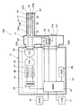
図1は本発明の実施形態を説明するための図で、内視鏡装置の概念的なブロック構成図、図2は図1に示す内視鏡装置の一例としての外観図である。
内視鏡装置100は、内視鏡11と、この内視鏡11が接続される制御装置13とを有する。制御装置13には、画像情報等を表示する表示部15と、入力操作を受け付ける入力部17が接続されている。内視鏡11は、内視鏡挿入部19の先端から照明光を出射する照明光学系と、被観察領域を撮像する撮像素子21を含む撮像光学系とを有する、電子内視鏡である。
Hereinafter, embodiments of the present invention will be described in detail with reference to the drawings.
FIG. 1 is a diagram for explaining an embodiment of the present invention, and is a conceptual block diagram of an endoscope apparatus. FIG. 2 is an external view as an example of the endoscope apparatus shown in FIG.
The
図1,図2に示すように、内視鏡11は、被検体内に挿入される内視鏡挿入部19と、内視鏡挿入部19の先端の湾曲操作や観察のための操作を行う操作部23と、内視鏡11を制御装置13に着脱自在に接続するコネクタ部25A,25Bを備える。なお、図示はしないが、内視鏡11の内部には、組織採取用処置具等を挿入する鉗子チャンネルや、送気・送水用のチャンネル等、各種のチャンネルが設けられる。
As shown in FIGS. 1 and 2, the
内視鏡挿入部19は、可撓性を持つ軟性部31と、湾曲部33と、先端部(以降、内視鏡先端部とも呼称する)35から構成される。内視鏡先端部35には、被観察領域へ光を照射する照射口37A,37Bと、被観察領域の画像情報を取得するCCD(Charge Coupled Device)イメージセンサやCMOS(Complementary Metal-Oxide Semiconductor)イメージセンサ等の撮像素子21が配置されている。なお、撮像素子21には焦点距離を制御するズーム機能と、被写体に焦点を合わせるオートフォーカス機能を有する対物レンズユニット39が取り付けられている。
The
湾曲部33は、軟性部31と先端部35との間に設けられ、操作部23に配置されたアングルノブ22の回動操作やアクチュエータの作動等により湾曲自在にされている。この湾曲部33は、内視鏡11が使用される被検体の部位等に応じて、任意の方向、任意の角度に湾曲でき、内視鏡先端部35の照射口37A,37B及び撮像素子21の観察方向を、所望の観察部位に向けることができる。また、図示は省略するが、内視鏡挿入部19の照射口37A,37Bには、カバーガラスやレンズが配置される。
The
制御装置13は、内視鏡先端部35の照射口37A,37Bに供給する照明光を発生する光源装置41、撮像素子21からの画像信号を画像処理するプロセッサ43を備え、コネクタ部25A,25Bを介して内視鏡11と接続される。また、プロセッサ43には、前述の表示部15と入力部17が接続されている。プロセッサ43は、内視鏡11の操作部23や入力部17からの指示に基づいて、内視鏡11から伝送されてくる撮像信号を画像処理し、表示部15へ表示用画像を生成して供給する。
The
光源装置41は、中心波長445nmの青色レーザ光源(第1の光源)45と、中心波長405nmの紫色レーザ光源(第2の光源)47とを発光源として備えている。これらの各光源45,47の半導体発光素子からの発光は、光源制御部49により個別に制御されており、青色レーザ光源45の出射光と、紫色レーザ光源47の出射光との光量比は変更自在になっている。つまり、光源制御部49は照明光の色調制御手段として機能する。
The
青色レーザ光源45及び紫色レーザ光源47は、ブロードエリア型のInGaN系レーザダイオードが利用でき、また、InGaNAs系レーザダイオードやGaNAs系レーザダイオードを用いることもできる。また、上記光源として、発光ダイオード等の発光体を用いた構成としてもよい。
As the blue
これら各光源45,47から出射されるレーザ光は、集光レンズ(図示略)によりそれぞれ光ファイバに入力され、合波器であるコンバイナ51と、分波器であるカプラ53を介してコネクタ部25Aに伝送される。なお、これに限らず、コンバイナ51とカプラ53を用いずに各光源45,47からのレーザ光を直接コネクタ部25Aに送出する構成であってもよい。
Laser light emitted from each of the
コネクタ部25Aに供給された中心波長445nmの青色レーザ光、及び中心波長405nmの紫色レーザ光が合波されたレーザ光は、光ファイバ55A,55Bによって、それぞれ内視鏡11の内視鏡先端部35まで伝搬される。そして、青色レーザ光は、内視鏡先端部35の光ファイバ55A,55Bの光出射端に配置された波長変換部材である蛍光体57を励起して蛍光を発光させる。また、一部の青色レーザ光は、そのまま蛍光体57を透過する。紫色レーザ光は、蛍光体57を励起させることなく透過して、狭帯域波長の照明光となる。
The laser beam obtained by combining the blue laser beam having the central wavelength of 445 nm and the purple laser beam having the central wavelength of 405 nm supplied to the
光ファイバ55A,55Bは、マルチモードファイバであり、一例として、コア径105μm、クラッド径125μm、外皮となる保護層を含めた径がφ0.3〜0.5mmの細径なケーブルを使用できる。
The
蛍光体57は、青色レーザ光の一部を吸収して緑色〜黄色に励起発光する複数種の蛍光体(例えばYAG系蛍光体、或いはBAM(BaMgAl10O17)等を含む蛍光体等)を含んで構成される。これにより、青色レーザ光を励起光とする緑色〜黄色の励起光と、蛍光体57により吸収されず透過した青色レーザ光とが合わされて、白色(疑似白色)の照明光となる。本構成例のように、半導体発光素子を励起光源として用いれば、高い発光効率で高強度の白色光が得られ、更に、白色光の強度を容易に調整できる。しかも、白色光の色温度、色度の変化を小さく抑えることができる。
The
上記の蛍光体57と光偏向・拡散部材59は、レーザ光の可干渉性により生じるスペックルに起因して、撮像の障害となるノイズの重畳や、動画像表示を行う際のちらつきの発生等の現象を防ぐことができる。また、蛍光体57は、蛍光体を構成する蛍光物質と、充填剤となる固定・固化用樹脂との屈折率差を考慮して、蛍光物質そのものと充填剤に対する粒径を、赤外域の光に対して吸収が小さく、かつ散乱が大きい材料で構成することが好ましい。これにより、赤色や赤外域の光に対して光強度を落とすことなく散乱効果が高められ、凹レンズ等の光路変更手段が不要となり、光学的損失が小さくなる。
The
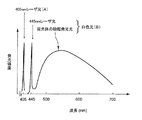
図3は、紫色レーザ光源47からの紫色レーザ光と、青色レーザ光源45からの青色レーザ光及び青色レーザ光が蛍光体57により波長変換された後の発光スペクトルを示すグラフである。紫色レーザ光は、中心波長405nmの輝線(プロファイルA)で表される。また、青色レーザ光は、中心波長445nmの輝線で表され、青色レーザ光による蛍光体57からの励起発光光は、概ね450nm〜700nmの波長帯域で発光強度が増大する分光強度分布となる。この励起発光光と青色レーザ光によるプロファイルBによって、前述した白色光が形成される。
FIG. 3 is a graph showing an emission spectrum after the wavelength conversion of the violet laser light from the violet
ここで、本明細書でいう白色光とは、厳密に可視光の全ての波長成分を含むものに限らず、例えばR,G,B等、特定の波長帯の光を含むものであればよく、例えば、緑色から赤色にかけての波長成分を含む光や、青色から緑色にかけての波長成分を含む光等も広義に含むものとする。 Here, the white light referred to in this specification is not limited to one that strictly includes all wavelength components of visible light, and may be any light that includes light in a specific wavelength band such as R, G, and B, for example. For example, light including a wavelength component from green to red, light including a wavelength component from blue to green, and the like are included in a broad sense.
この内視鏡装置100では、プロファイルAとプロファイルBとの発光強度を光源制御部49により相対的に増減制御して、任意の色調の照明光を生成するので、プロファイルA,Bの混合比率に応じて特性の異なる照明光を得ることができる。
In the
再び図1に戻り説明する。上記のように青色レーザ光と蛍光体57からの励起発光光、及び紫色レーザ光により形成される照明光は、内視鏡11の先端部35から被検体の被観察領域に向けて照射される。そして、照明光が照射された被観察領域の様子を対物レンズユニット39により撮像素子21上に結像させて撮像する。対物レンズユニット39は、ズーム制御部61によりズーム倍率を指定され、指定されたズーム倍率で合焦させる。
Returning again to FIG. As described above, the illumination light formed by the blue laser light, the excitation light emitted from the
撮像後に撮像素子21から出力される撮像画像の画像信号は、スコープケーブル63を通じてA/D変換器65に伝送されてデジタル信号に変換され、コネクタ部25bを介してプロセッサ43の制御部67に入力される。制御部67では、入力されたデジタル画像信号を画像データに変換して適宜な画像処理を行い、所望の出力用画像情報を生成する。そして、得られた画像情報は、内視鏡観察画像として表示部15に表示され、必要に応じて、メモリやストレージ装置からなる記憶部69に記憶される。
The image signal of the captured image output from the
記憶部69は、図示のようにプロセッサ43に内蔵されてもよく、プロセッサ43にネットワークを介して接続されていてもよい。なお、記憶部69に記憶される内視鏡観察画像の情報には、撮像時の光量比の情報を併せて記録することが好ましい。これにより、記憶された内視鏡観察画像に対して内視鏡観察後に正確な読影が行え、また、光量比に応じて、画像を標準化する等の適宜な画像処理を施すこともでき、内視鏡観察画像の活用範囲を拡げることができる。
The
上記構成の内視鏡装置100においては、内視鏡先端部35から出射する照明光の色調を連続的に変更することができる。また、レーザ光源を用いることで、高い分解能で色調が制御でき、色調の経時変化が少なく、しかも高い応答性で光量制御できる。また、発光効率が高いために省電力化が図られる。内視鏡診断においては、照明光の色調を診断に適した色調に合わせると、病変部の発見や診断が容易になることがあり、内視鏡診断中に照明光を任意のタイミングで変更自在にすることは診断精度を向上させる上で重要である。以下に、照明光の色調を各種のパラメータに応じて変更する内視鏡装置の構成例について順次説明する。
In the
<被観察領域の観察倍率に応じて照明光の色調を変更する構成>
まず、被観察領域と内視鏡先端部との距離に応じて色調を変更する構成例を説明する。被観察領域と内視鏡先端部35(図1参照)との距離である観察距離は、拡大観察する場合には短く、広い視野で観察する場合は長くされ、従って、観察倍率が高いほど観察距離が短くなる。この観察倍率は、対物レンズユニット39のズーム機構により内視鏡の術者が任意に設定する。ここで、対物レンズユニット39の一構成例を図4に示した。
<Configuration for changing color tone of illumination light according to observation magnification of observation area>
First, a configuration example will be described in which the color tone is changed according to the distance between the observation region and the endoscope distal end. The observation distance, which is the distance between the region to be observed and the endoscope distal end portion 35 (see FIG. 1), is short when magnifying and is long when observing with a wide field of view. The distance becomes shorter. This observation magnification is arbitrarily set by the endoscope operator by the zoom mechanism of the
図4に示すように、対物レンズユニット39の光学系は、撮像対象側から順に、固定レンズ71A、バリフォーカルレンズとして構成された変倍用の第1可動レンズ71B及び第2可動レンズ71C、固定レンズ71D及びフォーカス調整用の第3可動レンズ71Eが配置されており、この第3可動レンズ71Eの後側に、プリズム73、カバーガラス75を介して撮像素子21が配置される。この撮像素子21で撮像された信号は、回路基板77及び信号線79を介してプロセッサ43(図1参照)へ供給される。
As shown in FIG. 4, the optical system of the
上記の第1可動レンズ71Bは、係合孔81aを有する保持枠81に、第2可動レンズ71Cは係合孔83aを有する保持枠83に保持され、この係合孔81a,83aが円柱状のカム軸85の外周に嵌合する状態で、各レンズ71B,71Cはこのカム軸85に取り付けられる。上記の係合孔81aにはカムピン87が、係合孔81bにはカムピン89が突出配置され、カム軸85には、その軸線に対して傾斜角度の異なるカム溝91a,91bが形成されており、このカム溝91aに上記カムピン87が、カム溝91bに上記カムピン89が係合する。
The first
そして、上記カム軸85には、多重コイルバネ等からなる線状伝達部材93の一端が連結されており、この線状伝達部材93の他端は操作部23(図1参照)に設けられた図示しないモータの回転軸に取り付けられる。従って、モータの駆動によって線状伝達部材93を介してカム軸85を回転させれば、カム溝91a,91bとカムピン87,89の係合によって第1可動レンズ71B、第2可動レンズ71Cが光軸方向の前後にそれぞれ異なる量だけ移動し、これによって光学的変倍(拡大)等が行われる。即ち、第1及び第2の可動レンズ71B,71Cは、バリフォーカル光学系を構成しており、相対的に前後移動しながら光学的変倍を行う(観察距離、観察深度、焦点距離等が可変となる)。上記構成が変倍駆動機構となる。
One end of a
一方、上記フォーカス調整用の第3可動レンズ71Eを駆動するために、圧電素子を利用した小形で高速のアクチュエータ95が支持部97に取り付けられており、このアクチュエータ95の駆動軸95aの外周が、第3可動レンズ71Eの保持枠99の係合孔99aに移動可能に嵌合配置される。このアクチュエータ95では、駆動軸95aに圧電素子が取り付けられており、この圧電素子で駆動軸95aを緩急を以って前後に動かすことにより、第3可動レンズ71Eを前後方向へ移動させることができる。上記個性がフォーカス駆動機構となる。なお、このアクチュエータ95としては、静電アクチュエータ等の他の小形リニアアクチュエータを用いてもよい。
On the other hand, in order to drive the third
上記の対物レンズユニット39の光学系は、単純には図5に示すブロック構成図のようになる。つまり、ズーム制御部61は、対物レンズユニット39の変倍駆動機構111と、フォーカス駆動機構113を制御して、所望の倍率に設定すると共に、その倍率下で合焦させている。倍率の設定は、ズーム制御部61に接続されるズーム操作部115の操作により行われる。ズーム操作部115は、操作部23(図2参照)に配置された操作ボタン又はスライドスイッチであり、連続的に観察倍率が可変となるように構成される。
The optical system of the
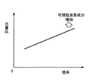
例えば、大腸の内視鏡診断においては、低倍率時には粘膜表面の形態や色味を観察し、高倍率時には表層の血管を観察することがあり、観察倍率に応じて照明光の好ましい色調が異なる。つまり、低倍率時には照明光が白色であることが好ましく、高倍率時には表層の血管情報を抽出する可視短波長成分を多く含む照明光であることが好ましい。 For example, in endoscopic diagnosis of the large intestine, the morphology and color of the mucous membrane surface may be observed when magnification is low, and blood vessels on the surface layer may be observed when magnification is high, and the preferred color tone of illumination light varies depending on the observation magnification. . That is, the illumination light is preferably white when the magnification is low, and is preferably illumination light including a lot of visible short wavelength components for extracting blood vessel information on the surface layer when the magnification is high.
そのため、図6に観察倍率と光量比との関係を示すように、観察倍率に応じて照明光の色調を変更する。具体的には、青色レーザ光源45と、紫色レーザ光源47の出射光量比を光源制御部49により制御して、ズーム制御部61による観察倍率が高いほど、紫色レーザ光源47の出射光量を増加させる。これにより、図3に示す短波長のプロファイルAと、白色光となるプロファイルBとの光量比が、観察倍率が高くなるほどプロファイルAの光量が増加し、より短波長の光成分を多く含む照明光となる。この色調の変更は、内視鏡の術者等のズーム操作に連動してリアルタイムで行われるため、応答性の高い制御が可能となる。なお、図4に示す関係は、直線状に限らず、非線形な曲線状であってもよく、階段状に変化する関係であってもよい。
Therefore, the color tone of the illumination light is changed according to the observation magnification so as to show the relationship between the observation magnification and the light amount ratio in FIG. Specifically, the light emission ratio between the blue
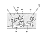
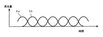
ここで、図5に生体組織の粘膜表層の血管を模式的に表した説明図を示した。生体組織の粘膜表層は、粘膜深層の血管B1から樹脂状血管網等の毛細血管B2が粘膜表層までの間に形成され、生体組織の病変はその毛細血管B2等の微細構造に現れることが報告されている。そこで、粘膜表層の毛細血管を画像強調して観察し、微小病変の早期発見や、病変範囲の診断が試みられている。 Here, FIG. 5 shows an explanatory diagram schematically showing blood vessels in the mucous membrane surface layer of the living tissue. It has been reported that the surface layer of the mucosa of the living tissue is formed between the blood vessel B1 of the deep mucosa and the capillary blood vessel B2 such as a resinous vascular network to the surface of the mucosa, and the lesion of the living tissue appears in the fine structure such as the capillary blood vessel B2. Has been. Therefore, it has been attempted to detect microscopic lesions at an early stage and diagnose the lesion area by observing capillary blood vessels on the surface of the mucosa with image enhancement.
生体組織に照明光が入射されると、入射光は生体組織内を拡散的に伝播するが、生体組織の吸収・散乱特性は波長依存性を有しており、短波長ほど散乱特性が強くなる傾向がある。つまり、照明光の波長によって光の深達度が変化する。そのため、照明光が400nm付近の波長域λaでは粘膜表層の毛細血管からの血管情報が得られ、波長500nm付近の波長域λbでは、更に深層の血管を含む血管情報が得られるようになる。そのため、生体組織表層の血管観察には、中心波長360〜800nm、好ましくは365〜515nm、更に好ましくは中心波長400nm〜470nmの光源が用いられる。 When illumination light enters a living tissue, the incident light propagates diffusively through the living tissue, but the absorption and scattering characteristics of the living tissue have wavelength dependence, and the shorter the wavelength, the stronger the scattering characteristics. Tend. That is, the depth of light changes depending on the wavelength of illumination light. Therefore, blood vessel information from capillaries on the mucosal surface layer is obtained when the illumination light is in the wavelength region λa near 400 nm, and blood vessel information including deeper blood vessels is obtained in the wavelength region λb near the wavelength of 500 nm. Therefore, a light source having a central wavelength of 360 to 800 nm, preferably 365 to 515 nm, and more preferably a central wavelength of 400 nm to 470 nm is used for blood vessel observation on the surface of the living tissue.
図8に内視鏡装置による観察画像の概略的な表示例を示すように、照明光を白色光とした場合の観察画像では、比較的粘膜深層の血管像が得られる反面、粘膜表層の微細な毛細血管はぼやけて見える。一方、可視短波長成分を多く含む照明光とした場合の観察画像では、粘膜表層の微細な毛細血管が鮮明に見えるようになる。 As shown in the schematic display example of the observation image by the endoscope apparatus in FIG. 8, in the observation image when the illumination light is white light, a relatively deep mucosal blood vessel image is obtained, but the fine mucosa surface layer is fine. Capillaries appear blurred. On the other hand, in the observation image when the illumination light includes a lot of visible short wavelength components, fine capillaries on the mucous membrane surface layer can be seen clearly.
つまり、観察倍率を高めて表層の血管を観察する場合は、照明光の色調が青みを強くするように制御し、観察倍率が低い場合は、照明光の青みを抑えて白色になるように制御すると、内視鏡の術者にとって診断に適した照明光となる。これにより、術者は観察倍率を調整する際に、青色レーザ光源45、紫色レーザ光源47の出射光量を併せて調整する等の煩わしい操作が不要となり、常に観察部位に最適な色調の照明光を自動的に得られるようになる。
In other words, when observing a blood vessel on the surface layer at a higher observation magnification, control the illumination light color tone to make it more bluish, and if the observation magnification is lower, control the illumination light to be less white and turn white. Then, it becomes illumination light suitable for diagnosis for an endoscope operator. This eliminates the need for troublesome operations such as adjusting the amount of light emitted from the blue
また、この内視鏡装置100によれば、照明光の色調の変更を光源45,47の駆動により行うため、カラーフィルタ等を用いて色調を変更する場合と比較して、光利用効率が増し、観察画像のノイズを低減できる。また、きめ細かな色調の調整が可能となる。
Further, according to the
上記の各光源45,47の駆動は、次のようにして行える。
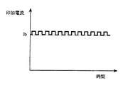
図1に示す光源制御部49は、制御部67からの指示に基づいて各光源45,47の出射光量を制御する。各光源45,47は、図9に示すような印加電流と発光量との関係R1を有しており、各光源45,47への印加電流を制御することで所望の発光量が得られる。例えば、発光量Laを得るためには、印加電流をIbとして関係R1に基づく発光量Lbを確保し、更に、微調整代としての発光量LbとLaとの差ΔLを、印加電流に、パルス変調されたパルス電流を重畳することで得る。
The above
The light
その場合の印加電流は、例えば、図10に印加電流のパルス電流重畳波形を示すように、発光量Laを、印加電流Ibをバイアスとするパルス電流により得る。パルス電流のパルス幅制御は、適宜なPWM回路により任意の波形が得られるため、発光量を正確に設定できる。このようなバイアス電流制御とパルス変調制御により、設定可能な発光量のダイナミックレンジを広く確保できる。 In this case, the applied current is obtained by, for example, a light emission amount La using a pulse current having the applied current Ib as a bias, as shown in FIG. In the pulse width control of the pulse current, an arbitrary waveform can be obtained by an appropriate PWM circuit, so that the light emission amount can be set accurately. By such bias current control and pulse modulation control, a wide dynamic range of light emission amount that can be set can be secured.
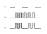
なお、この場合のパルス変調制御は、種々の駆動波形が利用できる。例えば、図11(a)に示すような撮像素子の画像1フレーム分の光蓄積時間と同期してオンオフを繰り返すパルス波形を用いれば、無駄な発熱を無くすことができる。また、図11(b)に示すような前記の光蓄積時間に対して十分に速い周期のパルス波形を用いれば、レーザのスペックルによる画像ノイズを低減できる。さらに、図11(c)に示すような、図11(a)のパルス波形のオン期間を図11(b)の速い周期のパルス波形とした(a)及び(b)の混合型のパルス波形を用いれば、上記の各効果を同時に享受できる。 In this case, various drive waveforms can be used for the pulse modulation control. For example, use of a pulse waveform that repeatedly turns on and off in synchronization with the light accumulation time for one image frame of the image sensor as shown in FIG. 11A can eliminate useless heat generation. Further, if a pulse waveform having a period sufficiently fast with respect to the light accumulation time as shown in FIG. 11B is used, image noise due to laser speckle can be reduced. Further, as shown in FIG. 11 (c), the ON period of the pulse waveform of FIG. 11 (a) is a pulse waveform having a fast cycle as shown in FIG. 11 (b), and the mixed pulse waveform of (a) and (b). By using the above, it is possible to simultaneously enjoy the above effects.
また、図12に示すように、各光源45,47を交互に点灯して、発光量が交互に最大となるように制御すると、光源45,47を合わせた光源装置41の最大駆動電力を抑えることができ、被検体である生体への負担も軽減できる。また、各光源45,47の照明光による撮像画像を個別に取得することもでき、その場合、取得した画像の画像間演算も可能となり、画像処理の自由度が向上する。
In addition, as shown in FIG. 12, when the
以上のように、被検体の被観察領域と内視鏡先端部35との接近度情報の一つである観察倍率に応じて、接近度が高いほど照明光の可視短波長成分の割合を増加させ、照明光の色調を自動的に変更することで、常に観察に適した色調の照明光が得られ、内視鏡操作の利便性が高められる。なお、ここでいう観察倍率とは、被観察領域に対する観察倍率であって、上述したような対物レンズユニット39により光学的に観察画像の画角を変化させる光学倍率に限らず、撮像素子21(図1参照)により得られた観察画像に対して、電気的に画角を変化させるデジタルズーム倍率であってもよい。デジタルズーム倍率とする場合は、図1に示す入力部17からの入力情報に基づいて、制御部67が光源制御部49に各光源45,47の出射光量比を指示する。
As described above, the proportion of the visible short wavelength component of the illumination light increases as the degree of proximity increases according to the observation magnification, which is one of the degree of proximity information between the observation region of the subject and the endoscope
また、内視鏡11の操作部23に設けた操作スイッチ117の操作により、観察倍率に変化が伴う観察モードの切り替えが行われる場合には、この操作スイッチ117の操作に同期して、上記の光量比の変更を行う構成としてもよい。
In addition, when the observation mode is changed by changing the observation magnification by the operation of the
<被観察領域からの光量に応じて照明光の色調を変更する構成>
次に、被観察領域と内視鏡先端部35との接近度情報に応じて照明光の色調を変更する他の例であって、撮像素子21から出力される撮像信号に対する被観察領域からの光量に応じて色調を変更する構成例を説明する。図13に示すように、被観察領域と内視鏡先端部との距離が離れる場合は、撮像素子21の受光量が減少し、距離が短い場合は受光量が増加する傾向がある。つまり、被観察領域と内視鏡先端部35との距離は、撮像素子21の受光量から推定できる。そこで、撮像素子21からの出力信号から、反射光の光量を示す信号(以下、A/E信号と称する)を生成して、このA/E信号に基づいて光源45,47の出射光量比を変更する。
<Configuration for changing the color tone of illumination light according to the amount of light from the observed area>
Next, another example of changing the color tone of the illumination light according to the information on the degree of proximity between the observation region and the endoscope
つまり、制御部67は、検出されたA/E信号の輝度が低いほど、被観察領域と内視鏡先端部との距離が短く、接近度が高いと判断して、光源制御部49に紫色レーザ光源47の出射光量の割合を増加させ、照明光の色調が青みを強くする。逆にA/E信号の輝度が高いほど、青色レーザ光源45の出射光量の割合を増加させ、照明光の青みを抑えて白色になるように制御する。
That is, the
この構成によれば、内視鏡観察時に常時連続的に得られる撮像素子21からの出力信号を利用して、被検体の被観察領域と内視鏡先端部35との接近度情報の一つである反射光の光量をA/E信号から求め、被観察領域と内視鏡先端部との距離を推定するので、高い応答性で照明光を常に最適な色調に変更できる。
According to this configuration, using the output signal from the
<被観察領域の部位に応じて照明光の色調を変更する構成>
次に、被観察領域の部位に応じて照明光の色調を変更する構成例を説明する。図14に本構成例による内視鏡装置の概略的なブロック構成図を示した。図14に示すように、内視鏡装置200は基本的に図1に示す構成と同様であり、制御装置13を病院内のネットワーク121に接続している。また、このネットワーク121には、受付端末123、サーバ125、診療科端末127等が接続され、内視鏡装置200との間で各種情報が共有されるようになっている。
<Configuration for changing the color tone of the illumination light according to the region of the observed region>
Next, a configuration example in which the color tone of the illumination light is changed according to the site of the observation area will be described. FIG. 14 shows a schematic block diagram of an endoscope apparatus according to this configuration example. As shown in FIG. 14, the
本内視鏡装置200の構成例においては、被検体となる患者の内視鏡による観察部位を検査オーダ情報から抽出し、この抽出された観察部位の情報に応じて、照明光の色調を変更する。照明光の色調を観察部位の診断に適した色調に合わせることで、病変部の発見や診断が容易となる。ここでは、病院内で患者が内視鏡検査を行うことを例に説明する。
In the configuration example of the
電子カルテや検査オーダリングシステム等の病院内管理システムの環境下で、まず、患者が病院内の受付端末123から受付処理を済ませると、受付情報がサーバ125へ送信される。サーバ125では、受付された患者情報を、サーバ125が有する大容量ハードディスク等の記憶装置を参照して、図15に示すように、登録された患者に対する患者ID、患者名、年齢等の患者情報と、検査予定がある場合は、その検査に対する検査部位、検査使用機器、担当医師等の検査情報を抽出する。
In the environment of an in-hospital management system such as an electronic medical record or an examination ordering system, first, when a patient completes an accepting process from the accepting
そして、サーバ125から患者情報と検査情報を含む検査オーダ情報が、内視鏡検査を行う特定の診療科の診療科端末127に送信されると、この特定の診療科において、上記患者の内視鏡検査が行われる。
When the examination order information including the patient information and the examination information is transmitted from the
このとき使用される内視鏡装置が上記の内視鏡装置200であった場合、内視鏡装置200の制御部67は、所定のタイミングで検査オーダ情報の検査部位の情報を取得し、この検査部位に応じた照明光の色調に設定する。検査部位と照明光の色調との関係は、予め内視鏡装置200側の記憶部69に記憶され、制御部67はこの記憶されたテーブル情報を参照して、各光源45,47が所定の光量比となるように光源制御部49に指示する。
When the endoscope apparatus used at this time is the
この構成によれば、検査前に予め観察部位が分かっている場合に、内視鏡装置の照明光の色調を、例えば生体臓器毎の観察部位に応じて最適に設定することができる。例えば、同じ上部消化管内視鏡による内視鏡検査でも、胃と食道とを比較すると、血管の多い胃では赤みが強い。このため、内視鏡による胃の観察時には、撮像画像は、赤色成分が最初に飽和し、緑色と青色の光量が不足した状態になりやすく、観察画像のS/Nが劣化する。その場合は、光源の青色や緑色の成分の比率を増加させることで、赤色、緑色、青色の3色が共にS/Nの良い画像を得ることができる。なお、光源の色調を変更した場合には、撮像画像の色調を画像処理により色バランスを補正することで、観察画像を表示する表示部15における色味を一定に保持する。
According to this configuration, when the observation site is known in advance before the examination, the color tone of the illumination light of the endoscope apparatus can be optimally set according to the observation site for each living organ, for example. For example, even in endoscopy using the same upper gastrointestinal endoscope, redness is strong in a stomach with many blood vessels when comparing the stomach and esophagus. For this reason, at the time of observing the stomach with an endoscope, the picked-up image tends to be in a state where the red component is first saturated and the light amounts of green and blue are insufficient, and the S / N of the observed image deteriorates. In that case, by increasing the ratio of the blue and green components of the light source, it is possible to obtain an image with good S / N for all three colors of red, green and blue. When the color tone of the light source is changed, the color tone of the captured image is corrected by image processing to maintain the color tone of the
なお、上記の病院内管理システムによる検査部位の設定の他にも、例えば、内視鏡の術者が内視鏡装置200に対して検査部位の情報を入力することで、内視鏡装置200が自動的に観察部位に最適な照明光の色調に変更する等、種々の設定方法が利用可能である。
In addition to the setting of the examination part by the above-mentioned hospital management system, for example, when the endoscope operator inputs information on the examination part to the
<内視鏡の機種に応じて照明光の色調を変更する構成>
次に、内視鏡の機種に応じて照明光の色調を変更する構成例を説明する。図16に本構成例による内視鏡装置の概略的なブロック構成図を示した。図16に示すように、内視鏡装置300は基本的に図1に示す構成と同様であり、内視鏡11には、内視鏡11の個体識別情報を記憶した本体側記憶部131が内蔵されている。また、制御装置13は、サーバ125や記憶装置133の接続されたネットワーク121に接続されている。
<Configuration to change the color of the illumination light according to the endoscope model>
Next, a configuration example in which the color tone of the illumination light is changed according to the endoscope model will be described. FIG. 16 shows a schematic block diagram of an endoscope apparatus according to this configuration example. As shown in FIG. 16, the
本体側記憶部131は、ICメモリやICタグ等で構成され、ICメモリではフラッシュメモリ等のROM、あるいやRAM、ICタグではRFID(Radio frequency identification)等が利用可能である。ICタグとした場合は、コネクタ部25Bにリーダ装置を配置して、ICタグを読み取った信号を制御部67に入力する構成とすればよい。
The main body
本内視鏡装置300の構成例においては、内視鏡11に内蔵された本体側記憶部131が、内視鏡11の個体識別情報を記憶しており、内視鏡11が制御装置13にコネクタ部25Bを介して接続された際に、制御部67が内視鏡11の本体側記憶部131から個体識別情報を読み取ることで、制御部67は接続された内視鏡11を認識する。
In the configuration example of the
そして、制御部67は、接続された内視鏡11の個体識別情報に応じた照明光の色調に設定する。個体識別情報と照明光の色調との関係は、予め内視鏡装置300側の記憶部69に記憶され、制御部67はこの記憶されたテーブル情報を参照して、各光源45,47が所定の光量比となるように光源制御部49に指示する。
Then, the
上記の個体識別情報としては、例えば、検査の適用部位毎に異なる内視鏡11の機種名とすることができる。図17に内視鏡の機種名を含む個体識別情報の登録テーブルの一例を示す。この登録テーブルには、内視鏡11の機種名、製造番号、適用部位等の個体情報と、照明光の色調を変更するための光源の光量比の情報が含まれる。例えば、機種名「EC−100」の内視鏡では、検査の適用部位が大腸であり、各光源45,47(図16参照)の光量比をR12に設定する。
As said individual identification information, it can be set as the model name of the
この内視鏡装置300によれば、制御装置13に接続された内視鏡11の個体識別情報に応じて、その内視鏡11に最適な照明光の色調に変更できる。なお、登録テーブルには光量比に限らず、照明光の色調を指定するものであれば他のパラメータであってもよい。
According to the
また、内視鏡11の個体識別情報としては、上記の適用部位に対応する情報以外にも、内視鏡11の構成部材に対応した情報であってもよい。例えば、内視鏡11に用いる蛍光体57(図1参照)、光ファイバ55A,55B、固体撮像素子21、対物レンズユニット39、等の光学系部材の種類や成分等に関する情報であってもよい。
Further, the individual identification information of the
図18に内視鏡1に用いられる蛍光体の種類、固体差を含む固体識別情報の登録テーブルの一例を示す。この登録テーブルには、内視鏡11の機種名、製造番号、蛍光体種、ロット番号等の個体情報と、照明光の色調を変更するための光源の光量比の情報が含まれる。例えば、「EG−120」の内視鏡では、蛍光体種が「Y−5」、ロット番号が「514」であり、光量比がR24として規定されている。ロット番号は、製造メーカの製造時情報から、蛍光体種「Y−5」のより詳細な組成が特定できるので、蛍光体の組成によって微妙に変化する色調を、規定の色調に補正することができる。つまり、この特定された蛍光体に最適な光量比を正確に規定することが可能となる。
FIG. 18 shows an example of a registration table of solid identification information including types of phosphors used in the
このように、内視鏡11の個体識別情報に応じて照明光の色調を変更することで、使用する内視鏡11に最適な照明光の色調を簡単に設定することができる。
Thus, by changing the color tone of the illumination light according to the individual identification information of the
以上説明した内視鏡装置100,200,300は、2種類のレーザ光源45,47を合波・分波して、蛍光体57に導き、照明光を発生させていたが、これに限らず、他の光源装置の構成にすることも勿論可能である。以下に、照明装置の他の構成例を例示する。
In the
図19は光源装置41から内視鏡11までの光路を1本の光ファイバ55Aで構成した内視鏡装置の概略的な構成図である。この構成においては、中心波長445nmの青色レーザ光源45からの青色レーザ光が光ファイバ55Aに導入されるまでの光路途中に、中心波長405nmの紫色レーザ光源47からの紫色レーザ光を合流させるダイクロイックプリズム135を配置している。
FIG. 19 is a schematic configuration diagram of an endoscope apparatus in which an optical path from the
また、この場合の光ファイバ55Aの光出射側に配置される蛍光体137は、青色レーザ光源45からの青色レーザ光の一部を吸収して緑色〜黄色に励起発光し、吸収されず透過した青色レーザ光と合わせて白色光を形成すると共に、紫色レーザ光源47からの紫色レーザ光を殆ど吸収せずに透過させる性質を有する。そのため、蛍光体137には、青色レーザ光により高効率で励起発光して、青色レーザ光と合わせて白色光が形成される材料と、紫色レーザ光に対しては、蛍光体の発光光量が少なくなる材料とを用いる。
Further, in this case, the
なお、一般的に蛍光体137による波長変換には、原理的に発生する発熱等の波長変換損失(ストークスロス)が存在する。そのため、発光波長の長い励起波長を選択した方が蛍光体の発光効率が高く、蛍光体の発熱を抑制する上で有利になる。本構成では、上記理由により、長波長側のレーザ光により白色光を生成して、発光効率を高めた構成にしている。
In general, wavelength conversion by the
図19に示す光源装置41と蛍光体137による照明光の発光スペクトルの例を図20に示した。図20に示すように、紫色レーザ光によっても蛍光体137が励起されるが、この紫色レーザ光による蛍光体137の励起発光量は、青色レーザ光による励起発光量に比較して、数分の一(少なくとも1/3、望ましくは1/5、更に望ましくは1/10以下)である。この程度に紫色レーザ光による蛍光体137の励起発光を抑えることで、白色光の色温度を適正に維持できる。
An example of an emission spectrum of illumination light by the
上記構成によれば、複数のレーザ光の光路をダイクロイックプリズム135により統合させるため、光源装置41から内視鏡11の蛍光体137までを1本の光ファイバ55Aで導光させ、しかも、照明光の出射口を蛍光体137の1箇所に収められるので、スペース効率を高めて内視鏡挿入部の細径化に寄与できる。
According to the above configuration, in order to integrate the optical paths of the plurality of laser beams by the
また、青色レーザ光源45、紫色レーザ光源47の他に、更に他のレーザ光源を備える場合であっても、同様にダイクロイックプリズム等の光カップリング手段を介して光路を統合すればよい。また、蛍
光体137についても、他のレーザ光源の波長に励起しない、又は励起しにくい蛍光物質を用いればよい。
Further, in addition to the blue
ここで、上記構成例における具体的な蛍光体137の材料としては、例えば、特開2006−2115号公報に記載のような、添加元素として鉛(Pb)を含み4硫化2ガリウムカルシウム(CaGa2S4)を母体とする結晶性の固体蛍光材料、或いは、添加元素として鉛(Pb)とセリウム(Ce)を含み4硫化2ガリウムカルシウム(CaGa2S4)を母体とする結晶性の固体蛍光材料が使用できる。この蛍光体材料によれば、約460nm〜約660nmのほぼ可視全域に至る蛍光を得ることができ、白色光照明時における演色性が向上する。
Here, as a specific material of the
また、この他にも、緑色蛍光体であるLiTbW2O8(小田喜 勉、“白色LED用蛍光体について”、電子情報通信学会技術研究報告ED2005-28, CFM2005-20, SDM2005-28, pp.69-74(2005-05)等を参照)、ベータサイアロン(β−sialon:Eu)青色蛍光体(広崎 尚登、解 栄軍、佐久間 健、“サイアロン系信蛍光体とそれを用いた白色LEDの開発”、応用物理学会誌 第74巻、第11号、pp.1449-1452(2005)、或いは、山元 明 東京工科大パイオニクス学部、応用物理学会誌 第76巻 第3号、p.241(2007)を参照)、CaAlSiN3赤色蛍光体等を組み合わせて用いることができる。ベータサイアロンは、β型窒化ケイ素結晶にアルミニウムと酸とが固溶したSi6-zAl2O2N8-z(zは固溶量)の組成で示される結晶である。蛍光体137は、これらLiTbW2O8とベータサイアロン、CaAlSiN3を混在させたものとしてもよく、また、これらの蛍光体を層状に重ねた構成としてもよい。
In addition to this, LiTbW 2 O 8 which is a green phosphor (Yoshitoshi Oda, “About phosphor for white LED”, IEICE Technical Report ED2005-28, CFM2005-20, SDM2005-28, pp .69-74 (2005-05), etc.), beta-sialon (Eu) blue phosphor (Naoto Hirosaki, Hoei Gun, Ken Sakuma, “Sialon-based phosphor and white LED using it” Development, "Journal of Applied Physics, Vol. 74, No. 11, pp. 1449-1452 (2005), or Akira Yamamoto, Tokyo University of Technology, Department of Pionics, Vol. 76, No. 3, p. 2007)), a CaAlSiN 3 red phosphor or the like can be used in combination. Beta sialon is a crystal having a composition of Si 6-z Al 2 O 2 N 8-z (z is a solid solution amount) in which aluminum and an acid are dissolved in β-type silicon nitride crystal. The
図21は多数のレーザ光源を用いた他の内視鏡装置の例を示す概略的な構成図である。図21に示す構成によれば、例えば中心波長445nmの青色レーザ光源45からの青色レーザ光は、コネクタ部25Aを介して内視鏡11内の光ファイバ55Cに導入され、光ファイバ55Cの光出射端に配置された蛍光体57に照射される。そして、この青色レーザ光を励起光とする蛍光体57からの励起発光光と、蛍光体57を透過する青色レーザ光とによって白色光が生成される。
FIG. 21 is a schematic configuration diagram showing an example of another endoscope apparatus using a large number of laser light sources. According to the configuration shown in FIG. 21, for example, blue laser light from a blue
また、例えば中心波長405nmの紫色レーザ光源47、例えば中心波長515nmの青緑色レーザ光源141、例えば中心波長630nmの赤色レーザ光源143からの各レーザ光が、コネクタ部25Aを介して光ファイバ55D,55E,55Fにそれぞれ導入され、光偏向・拡散部材145,147,149を通じて、それぞれ紫色、青緑色、赤色の照明光となる。
Further, for example, laser beams from a violet
光偏向・拡散部材145,147,149は、入射されたレーザ光を透過させる材料であればよく、例えば透光性を有する樹脂材料やガラス等が用いられる。更には、光偏向・拡散部材145,147,149は、樹脂材料やガラスの表面等に、微小凹凸や屈折率の異なる粒子(フィラー等)を混在させた光拡散層を設けた構成や、半透明体の材料を用いた構成としてもよい。これにより、光偏向・拡散部材145,147,149から出射する透過光は、所定の照射領域内で光量が均一化された狭帯域波長の照明光となる。
The light deflecting / diffusing
このように、発光波長の異なる多数のレーザ光源を用い、各光源の光量比を調整して照明光を生成すれば、光源制御部49の生成可能な色調範囲を拡大でき、観察に適した色調の調整範囲を拡げることができる。また、微妙な色調の調整を容易にしかも正確に行える。
In this way, by using a large number of laser light sources having different emission wavelengths and adjusting the light quantity ratio of each light source to generate illumination light, the color tone range that can be generated by the light
なお、上記光ファイバ55C,55D,55E,55Fは、使用する波長に応じてそれぞれ最適なファイバを選定して用いることが好ましい。光ファイバのコアは、水酸基(OH−)濃度の高/低により伝送損失が変化する波長依存性を有し、赤外域の特定の波長では可視域の波長とは異なる吸収率となる。そのため、光源の波長が650nm以下の場合は高水酸基濃度のコアの光ファイバを用い、650nmを超える場合は低水酸基濃度のコアの光ファイバを用いるようにする。
The
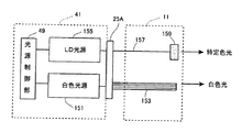
図22は白色光源とレーザ光源を用いた他の内視鏡装置の例を示す概略的な構成図である。本構成例においては、白色光源151としてハロゲンランプ、キセノンランプ、或いは白色発光ダイオード等のブロードな波長帯の光を出射する光源を用い、光ファイバ束であるライトガイド153を通じて内視鏡11の先端部から白色光を照射する。照明光の色調は、1つ又は複数種のレーザ光源155の出射光量に応じて変更する。レーザ光源155からの出射光は、コネクタ部25を介して、光ファイバ157により内視鏡先端部まで伝送され、光ファイバ157の光出射端に配置された光偏向・拡散部材159から特定色の照明光として供される。また、光偏向・拡散部材159に代えて蛍光体を配置して所望の色の蛍光を照明光としてもよい。
FIG. 22 is a schematic configuration diagram showing an example of another endoscope apparatus using a white light source and a laser light source. In this configuration example, a light source that emits light in a broad wavelength band such as a halogen lamp, a xenon lamp, or a white light emitting diode is used as the
上記構成によれば、簡単な構成で照明光の色調の変更が可能となる。 According to the above configuration, the color tone of the illumination light can be changed with a simple configuration.
図23は内視鏡11の先端部に発光ダイオードを設けた内視鏡装置の例を示す概略的な構成図である。本構成例においては、内視鏡11の先端部に発光ダイオードを配置する。発光ダイオードとしては、例えば、青色発光ダイオード161、緑色発光ダイオード163、赤色発光ダイオード165を用い、光源装置41側の光源制御部49に接続されたドライバ167により、発光量をそれぞれ個別に制御する。
FIG. 23 is a schematic configuration diagram showing an example of an endoscope apparatus in which a light emitting diode is provided at the distal end portion of the
この構成によれば、光の三原色の発光素子を用いることで白色を含む任意の色調の照明光が得られる。また、白色光の光量を稼ぐために白色光源169を別途に設けて、内視鏡11に白色光を供給する構成としてもよい。この場合の白色光源169としては、ハロゲンランプ、キセノンランプ、白色発光ダイオード、或いは、前述のレーザ光源と蛍光体との組合せによる光源が利用可能である。
According to this configuration, illumination light having an arbitrary color tone including white can be obtained by using light emitting elements of the three primary colors of light. Alternatively, a
上記の各内視鏡装置の構成においては、照明光の色調を光源制御部49によって各光源の出射光量の調整により制御しているが、この他、各光源の出射光量を変更することなく、色調を変更することもできる。例えば、各光源を個別に点灯させ、それぞれの点灯タイミングにおける撮像素子21の露光時間を変更することで、擬似的に照明光の色調を変更する。即ち、各光源と撮像素子21とを同期制御して、例えば青色レーザ光源等の第1の光源のみ点灯させて撮像する撮像素子21の露光時間と、例えば白色光源などの第2の光源のみ点灯させて撮像する露光時間との、各露光時間をそれぞれ個別に増減調整し、得られる各撮像画像を合成して観察画像データとする。この観察画像データは、各光源下での露光時間がその光源の光量に相当するため、照明光の色調が擬似的に変化したものとみなせる。つまり、光源の出射光量比により照明光の色調を直接的に制御することに代えて、光源と撮像素子とを同期制御する撮像制御手段により、撮像素子21の露光時間を各照明光下で個別に調整することでも、間接的に照明光の色調を変更することができる。
In the configuration of each endoscope apparatus described above, the color tone of the illumination light is controlled by adjusting the emitted light amount of each light source by the light
このように、本発明は上記の実施形態に限定されるものではなく、明細書の記載、並びに周知の技術に基づいて、当業者が変更、応用することも本発明の予定するところであり、保護を求める範囲に含まれる。 As described above, the present invention is not limited to the above-described embodiments, and modifications and applications by those skilled in the art based on the description of the specification and well-known techniques are also within the scope of the present invention. It is included in the range to calculate.
以上の通り、本明細書には次の事項が開示されている。
(1) 照明光を内視鏡先端部から出射する照明手段と、前記照明光の照射された被検体の被観察領域を撮像する撮像素子を有する撮像手段と、を備えた内視鏡装置であって、
前記照明手段が発光波長の異なる複数種の光源を有し、
前記複数種の光源の各出射光量の比率を変更して前記照明光の色調を変更する色調制御手段を備えた内視鏡装置。
この内視鏡装置によれば、観察対象に応じて、又は拡大観察等の種々の診断場面に応じて、照明光の色調を任意に変更することができ、最適な色調の照明光で観察することができる。
As described above, the following items are disclosed in this specification.
(1) An endoscope apparatus comprising: an illuminating unit that emits illumination light from an endoscope distal end; and an imaging unit that includes an imaging element that captures an observation region of the subject irradiated with the illumination light. There,
The illumination means has a plurality of types of light sources having different emission wavelengths,
An endoscope apparatus comprising color tone control means for changing the color tone of the illumination light by changing the ratio of the amounts of emitted light of the plurality of types of light sources.
According to this endoscope apparatus, the color tone of the illumination light can be arbitrarily changed according to the observation target or according to various diagnostic scenes such as magnified observation, and observation is performed with the illumination light having the optimum color tone. be able to.
(2) (1)の内視鏡装置であって、
前記色調制御手段が、前記照明光の色調を連続変化可能に構成された内視鏡装置。
この内視鏡装置によれば、微妙な色調の調整が可能となり、目的とする照明光の色調が正確に得られる。
(2) The endoscope apparatus according to (1),
An endoscope apparatus in which the color tone control means is configured to be able to continuously change the color tone of the illumination light.
According to this endoscope apparatus, it is possible to finely adjust the color tone, and the desired color tone of the illumination light can be obtained accurately.
(3) (1)又は(2)の内視鏡装置であって、
前記複数の光源の少なくともいずれかが半導体発光素子を発光源とする光源である内視鏡装置。
この内視鏡装置によれば、高い分解能で色調が制御でき、色調の経時変化が少なく、しかも高い応答性で光量制御できる。また、発光効率が高いために省電力化が図られる。
(3) The endoscope apparatus according to (1) or (2),
An endoscope apparatus, wherein at least one of the plurality of light sources is a light source having a semiconductor light emitting element as a light source.
According to this endoscope apparatus, the color tone can be controlled with high resolution, the change in the color tone with time is small, and the light amount can be controlled with high response. Moreover, since the luminous efficiency is high, power saving can be achieved.
(4) (1)〜(3)のいずれかの内視鏡装置であって、
前記複数の光源の少なくともいずれかが白色光源である内視鏡装置。
この内視鏡装置によれば、白色光源からの白色照明光に他の特定色の光源光が配分されることで、十分な光量を確保した上で色調の変更を容易に行うことができる。
(4) The endoscope apparatus according to any one of (1) to (3),
An endoscope apparatus in which at least one of the plurality of light sources is a white light source.
According to this endoscope apparatus, the light source light of another specific color is distributed to the white illumination light from the white light source, so that it is possible to easily change the color tone while securing a sufficient amount of light.
(5) (4)の内視鏡装置であって、
前記白色光源が、半導体発光素子を発光源とする励起光源と、該励起光源からの出射光により励起発光する蛍光体とを含む内視鏡装置。
この内視鏡装置によれば、特定の狭い波長帯の励起光源からの出射光と、この出射光により蛍光体を励起発光させた励起発光光とによって、広い波長帯の照明光が得られる。
(5) The endoscope apparatus according to (4),
An endoscope apparatus, wherein the white light source includes an excitation light source using a semiconductor light emitting element as a light source, and a phosphor that emits light by excitation light emitted from the excitation light source.
According to this endoscope apparatus, illumination light in a wide wavelength band can be obtained by light emitted from an excitation light source having a specific narrow wavelength band and excitation light emitted by exciting the phosphor with the emitted light.
(6) (1)〜(5)のいずれかの内視鏡装置であって、
前記色調制御手段が、前記被検体の被観察領域と前記内視鏡先端部との接近度情報に基づいて前記色調を制御する内視鏡装置。
この内視鏡装置によれば、被観察領域と内視鏡先端部との距離を表す接近度情報に応じて色調を制御することで、観察対象や診断場面毎に照明光を実質的に最適にできる。
(6) The endoscope apparatus according to any one of (1) to (5),
An endoscope apparatus in which the color tone control unit controls the color tone based on proximity information between an observation area of the subject and the endoscope distal end portion.
According to this endoscope apparatus, the illumination light is substantially optimized for each observation target and diagnosis scene by controlling the color tone according to the proximity information indicating the distance between the observed region and the endoscope tip. Can be.
(7) (6)の内視鏡装置であって、
前記色調制御手段が、前記接近度情報の接近度が高いほど、前記撮像画像に含まれる可視短波長成分の割合を増加させる内視鏡装置。
この内視鏡装置によれば、接近度が高いほど、つまり、被観察領域と内視鏡先端部との距離が短いほど、可視短波長成分の割合を増加させることで、例えば、表層血管を観察したい場合に血管情報を画像強調することができる。
(7) The endoscope apparatus according to (6),
An endoscope apparatus in which the color tone control unit increases the proportion of a visible short wavelength component included in the captured image as the approach degree of the approach degree information is higher.
According to this endoscope apparatus, the higher the degree of approach, that is, the shorter the distance between the observed region and the endoscope tip, the greater the proportion of visible short wavelength components, for example, When it is desired to observe, blood vessel information can be image-enhanced.
(8) (6)又は(7)の内視鏡装置であって、
前記接近度情報が、前記被観察領域に対する観察倍率を表す倍率情報である内視鏡装置。
この内視鏡装置によれば、被観察領域と内視鏡先端部との接近度の高低に連動する観察倍率の情報を用いることで、接近度に応じた色調に変更でき、実質的に観察対象や診断場面毎に最適な観察が行える。
(8) The endoscope apparatus according to (6) or (7),
An endoscope apparatus in which the proximity information is magnification information representing an observation magnification with respect to the observation region.
According to this endoscope apparatus, it is possible to change the color tone according to the degree of approach and to substantially observe by using the information of the observation magnification that is linked to the degree of approach between the observation region and the tip of the endoscope. Optimal observation can be performed for each target and diagnosis scene.
(9) (8)の内視鏡装置であって、
前記倍率情報が、前記撮像手段により得られる観察画像に対し、光学的に前記観察画像の画角を変化させる撮像光学系の光学倍率の情報である内視鏡装置。
この内視鏡装置によれば、内視鏡の術者等による光学倍率の変更操作に同期して色調を変更するため、色調変更をリアルタイムで迅速に行うことができる。
(9) The endoscope apparatus according to (8),
An endoscope apparatus in which the magnification information is information on an optical magnification of an imaging optical system that optically changes an angle of view of the observation image with respect to an observation image obtained by the imaging means.
According to this endoscope apparatus, since the color tone is changed in synchronization with the optical magnification changing operation by an endoscope operator or the like, the color tone can be quickly changed in real time.
(10) (8)の内視鏡装置であって、
前記倍率情報が、前記撮像手段により得られる観察画像に対し、電気的に画角を変化させるデジタルズーム倍率の情報である内視鏡装置。
この内視鏡装置によれば、内視鏡の術者等によるデジタルズーム倍率の変更操作に同期して色調を変更するため、色調変更をリアルタイムで迅速に行うことができる。
(10) The endoscope apparatus according to (8),
An endoscope apparatus, wherein the magnification information is information on a digital zoom magnification that electrically changes an angle of view with respect to an observation image obtained by the imaging unit.
According to this endoscope apparatus, since the color tone is changed in synchronization with the digital zoom magnification change operation by an endoscope operator or the like, the color tone can be quickly changed in real time.
(11) (6)又は(7)の内視鏡装置であって、
前記接近度情報が、前記撮像手段により得られる撮像画像の光量情報である内視鏡装置。
この内視鏡装置によれば、内視鏡観察時に常時連続的に得られる撮像素子から出力される光量情報を利用して色調を変更するので、高い応答性で常に最適な色調に合わせることができる。
(11) The endoscope apparatus according to (6) or (7),
An endoscope apparatus in which the proximity information is light amount information of a captured image obtained by the imaging unit.
According to this endoscope apparatus, since the color tone is changed using the light amount information output from the image pickup device that is continuously obtained at the time of endoscopic observation, it is possible to always match the optimum color tone with high responsiveness. it can.
(12) (11)の内視鏡装置であって、
前記色調制御手段が、前記光量情報の光量値が低いほど前記接近度が高いと判断する内視鏡装置。
この内視鏡装置によれば、被観察領域と内視鏡先端部との距離が離れるほど、撮像素子の受光量が減少することを利用して、接近度を推定することができる。
(12) The endoscope apparatus according to (11),
An endoscope apparatus in which the color tone control unit determines that the degree of approach is higher as the light amount value of the light amount information is lower.
According to this endoscope apparatus, the degree of approach can be estimated by utilizing the fact that the amount of light received by the image sensor decreases as the distance between the observed region and the endoscope distal end increases.
(13) (1)〜(5)のいずれかの内視鏡装置であって、
前記色調制御手段が、前記被検体の観察部位の情報に基づいて前記色調を制御する内視鏡装置。
この内視鏡装置によれば、観察部位の診断に適した色調に合わせることで、病変部の発見や診断が容易となる。
(13) The endoscope apparatus according to any one of (1) to (5),
An endoscope apparatus in which the color tone control unit controls the color tone based on information on an observation site of the subject.
According to this endoscope apparatus, it becomes easy to find and diagnose a lesioned part by matching the color tone suitable for diagnosis of the observation site.
(14) (13)の内視鏡装置であって、
前記観察部位の情報が、前記被検体の生体臓器毎に規定された情報である内視鏡装置。
この内視鏡装置によれば、生体臓器毎に診断に最適な色調に合わせることができる。
(14) The endoscope apparatus according to (13),
An endoscope apparatus in which the information on the observation site is information defined for each living organ of the subject.
According to this endoscope apparatus, it is possible to adjust the color tone optimal for diagnosis for each living organ.
(15) (1)〜(5)のいずれかの内視鏡装置であって、
前記内視鏡先端部を含む内視鏡本体と、該内視鏡本体が接続される内視鏡制御部と、を備え、
前記内視鏡本体に該内視鏡本体の個体識別情報を記憶する本体側記憶部を有し、
前記色調制御手段が、前記本体記憶部に記憶された個体識別情報に基づいて、前記色調を制御する内視鏡装置。
この内視鏡装置によれば、内視鏡本体の個体識別情報に応じて最適な色調にできる。
(15) The endoscope apparatus according to any one of (1) to (5),
An endoscope body including the endoscope distal end, and an endoscope control unit to which the endoscope body is connected,
A main body side storage unit that stores individual identification information of the endoscope main body in the endoscope main body,
An endoscope apparatus in which the color tone control unit controls the color tone based on individual identification information stored in the main body storage unit.
According to this endoscope apparatus, an optimum color tone can be obtained according to the individual identification information of the endoscope body.
(16) (15)の内視鏡装置であって、
前記内視鏡本体が対応可能な被検体の適用部位の情報を有する機種情報が前記個体識別情報に含まれ、
前記色調制御手段が前記機種情報に応じて前記色調を制御する内視鏡装置。
この内視鏡装置によれば、適用部位に応じた色調で観察が行える。
(16) The endoscope device according to (15),
Model information including information on the application site of the subject that can be supported by the endoscope body is included in the individual identification information,
An endoscope apparatus in which the color tone control means controls the color tone according to the model information.
According to this endoscope apparatus, observation can be performed with a color tone according to the application site.
(17) (16)の内視鏡装置であって、
少なくともいずれかの前記光源からの光を励起光として励起発光する蛍光体が前記内視鏡本体に配置され、
前記蛍光体の組成を表す個体情報が前記個体識別情報に含まれ、
前記色調制御手段が前記蛍光体の個体情報に応じて前記色調を制御する内視鏡装置。
この内視鏡装置によれば、蛍光体の組成によって変化する色調を、所望の色調に正確に補正することができる。
(17) The endoscope device according to (16),
A phosphor that emits and emits light using at least light from the light source as excitation light is disposed in the endoscope body,
Individual information representing the composition of the phosphor is included in the individual identification information,
An endoscope apparatus in which the color tone control means controls the color tone according to individual information of the phosphor.
According to this endoscope apparatus, the color tone that changes depending on the composition of the phosphor can be accurately corrected to a desired color tone.
11 内視鏡
13 制御装置
15 表示部
21 撮像素子
23 操作部
35 先端部
37A,37B 照射口
39 対物レンズユニット
41 光源装置
43 プロセッサ
45 青色レーザ光源
47 紫色レーザ光源
49 光源制御部(色調制御手段)
55A,55B 光ファイバ
57 蛍光体
61 ズーム制御部
67 制御部
69 記憶部
100,200,300 内視鏡装置
111 変倍駆動機構
113 フォーカス駆動機構
115 ズーム操作部
117 操作スイッチ
121 ネットワーク
131 本体側記憶部
133 記憶装置
141 青緑色レーザ光源
143 赤色レーザ光源
145,147,149 光偏向・拡散部材
151 白色光源
155 レーザ光源
159 光偏向・拡散部材
161 青色発光ダイオード
163 緑色発光ダイオード
165 赤色発光ダイオード
DESCRIPTION OF
55A,
つまり、制御部67は、検出されたA/E信号の輝度が高いほど、被観察領域と内視鏡先端部との距離が短く、接近度が高いと判断して、光源制御部49に紫色レーザ光源47の出射光量の割合を増加させ、照明光の色調が青みを強くする。逆にA/E信号の輝度が低いほど、青色レーザ光源45の出射光量の割合を増加させ、照明光の青みを抑えて白色になるように制御する。
That is, the
Claims (17)
察領域を撮像する撮像素子を有する撮像手段と、を備えた内視鏡装置であって、
前記照明手段が発光波長の異なる複数種の光源を有し、
前記複数種の光源の各出射光量の比率を変更して前記照明光の色調を変更する色調制御
手段を備えた内視鏡装置。 An endoscope apparatus comprising: an illuminating unit that emits illumination light from a distal end portion of an endoscope; and an imaging unit that includes an imaging element that captures an observation region of a subject irradiated with the illumination light.
The illumination means has a plurality of types of light sources having different emission wavelengths,
An endoscope apparatus comprising color tone control means for changing the color tone of the illumination light by changing the ratio of the amounts of emitted light of the plurality of types of light sources.
前記色調制御手段が、前記照明光の色調を連続変化可能に構成された内視鏡装置。 The endoscope apparatus according to claim 1,
An endoscope apparatus in which the color tone control means is configured to be able to continuously change the color tone of the illumination light.
前記複数の光源の少なくともいずれかが半導体発光素子を発光源とする光源である内視
鏡装置。 The endoscope apparatus according to claim 1 or 2,
An endoscope apparatus, wherein at least one of the plurality of light sources is a light source having a semiconductor light emitting element as a light source.
前記複数の光源の少なくともいずれかが白色光源である内視鏡装置。 The endoscope apparatus according to any one of claims 1 to 3,
An endoscope apparatus in which at least one of the plurality of light sources is a white light source.
前記白色光源が、半導体発光素子を発光源とする励起光源と、該励起光源からの出射光
により励起発光する蛍光体とを含む内視鏡装置。 The endoscope apparatus according to claim 4, wherein
An endoscope apparatus, wherein the white light source includes an excitation light source using a semiconductor light emitting element as a light source, and a phosphor that emits light by excitation light emitted from the excitation light source.
前記色調制御手段が、前記被検体の被観察領域と前記内視鏡先端部との接近度情報に基
づいて前記色調を制御する内視鏡装置。 The endoscope apparatus according to any one of claims 1 to 5,
An endoscope apparatus in which the color tone control unit controls the color tone based on proximity information between an observation area of the subject and the endoscope distal end portion.
前記色調制御手段が、前記接近度情報の接近度が高いほど、前記撮像画像に含まれる可
視短波長成分の割合を増加させる内視鏡装置。 The endoscope apparatus according to claim 6, wherein
An endoscope apparatus in which the color tone control unit increases the proportion of a visible short wavelength component included in the captured image as the approach degree of the approach degree information is higher.
前記接近度情報が、前記被観察領域に対する観察倍率を表す倍率情報である内視鏡装置
。 The endoscope apparatus according to claim 6 or 7, wherein
An endoscope apparatus in which the proximity information is magnification information representing an observation magnification with respect to the observation region.
前記倍率情報が、前記撮像手段により得られる観察画像に対し、光学的に前記観察画像
の画角を変化させる撮像光学系の光学倍率の情報である内視鏡装置。 The endoscope apparatus according to claim 8, wherein
An endoscope apparatus in which the magnification information is information on an optical magnification of an imaging optical system that optically changes an angle of view of the observation image with respect to an observation image obtained by the imaging means.
前記倍率情報が、前記撮像手段により得られる観察画像に対し、電気的に画角を変化さ
せるデジタルズーム倍率の情報である内視鏡装置。 The endoscope apparatus according to claim 8, wherein
An endoscope apparatus, wherein the magnification information is information on a digital zoom magnification that electrically changes an angle of view with respect to an observation image obtained by the imaging unit.
前記接近度情報が、前記撮像手段により得られる撮像画像の光量情報である内視鏡装置
。 The endoscope apparatus according to claim 6 or 7, wherein
An endoscope apparatus in which the proximity information is light amount information of a captured image obtained by the imaging unit.
前記色調制御手段が、前記光量情報の光量値が低いほど前記接近度が高いと判断する内
視鏡装置。 The endoscope apparatus according to claim 11, wherein
An endoscope apparatus in which the color tone control unit determines that the degree of approach is higher as the light amount value of the light amount information is lower.
前記色調制御手段が、前記被検体の観察部位の情報に基づいて前記色調を制御する内視
鏡装置。 The endoscope apparatus according to any one of claims 1 to 5,
An endoscope apparatus in which the color tone control unit controls the color tone based on information on an observation site of the subject.
前記観察部位の情報が、前記被検体の生体臓器毎に規定された情報である内視鏡装置。 An endoscope apparatus according to claim 13,
An endoscope apparatus in which the information on the observation site is information defined for each living organ of the subject.
前記内視鏡先端部を含む内視鏡本体と、該内視鏡本体が接続される内視鏡制御部と、を
備え、
前記内視鏡本体に該内視鏡本体の個体識別情報を記憶する本体側記憶部を有し、
前記色調制御手段が、前記本体記憶部に記憶された個体識別情報に基づいて、前記色調
を制御する内視鏡装置。 The endoscope apparatus according to any one of claims 1 to 5,
An endoscope body including the endoscope distal end, and an endoscope control unit to which the endoscope body is connected,
A main body side storage unit that stores individual identification information of the endoscope main body in the endoscope main body,
An endoscope apparatus in which the color tone control unit controls the color tone based on individual identification information stored in the main body storage unit.
前記内視鏡本体が対応可能な被検体の適用部位の情報を有する機種情報が前記個体識別
情報に含まれ、
前記色調制御手段が前記機種情報に応じて前記色調を制御する内視鏡装置。 The endoscope apparatus according to claim 15, wherein
Model information including information on the application site of the subject that can be supported by the endoscope body is included in the individual identification information,
An endoscope apparatus in which the color tone control means controls the color tone according to the model information.
少なくともいずれかの前記光源からの光を励起光として励起発光する蛍光体が前記内視鏡本体に配置され、
前記蛍光体の組成を表す個体情報が前記個体識別情報に含まれ、
前記色調制御手段が前記蛍光体の個体情報に応じて前記色調を制御する内視鏡装置。 The endoscope apparatus according to claim 16, wherein
A phosphor that emits and emits light using at least light from the light source as excitation light is disposed in the endoscope body,
Individual information representing the composition of the phosphor is included in the individual identification information,
An endoscope apparatus in which the color tone control means controls the color tone according to individual information of the phosphor.
Priority Applications (1)
| Application Number | Priority Date | Filing Date | Title |
|---|---|---|---|
| JP2013216169A JP2014014716A (en) | 2013-10-17 | 2013-10-17 | Endoscopic apparatus |
Applications Claiming Priority (1)
| Application Number | Priority Date | Filing Date | Title |
|---|---|---|---|
| JP2013216169A JP2014014716A (en) | 2013-10-17 | 2013-10-17 | Endoscopic apparatus |
Related Parent Applications (1)
| Application Number | Title | Priority Date | Filing Date |
|---|---|---|---|
| JP2009185687A Division JP5401205B2 (en) | 2009-08-10 | 2009-08-10 | Endoscope device |
Related Child Applications (2)
| Application Number | Title | Priority Date | Filing Date |
|---|---|---|---|
| JP2014227997A Division JP5922209B2 (en) | 2014-11-10 | 2014-11-10 | Endoscope device |
| JP2014227998A Division JP5879422B2 (en) | 2014-11-10 | 2014-11-10 | Endoscope device |
Publications (1)
| Publication Number | Publication Date |
|---|---|
| JP2014014716A true JP2014014716A (en) | 2014-01-30 |
Family
ID=50109912
Family Applications (1)
| Application Number | Title | Priority Date | Filing Date |
|---|---|---|---|
| JP2013216169A Pending JP2014014716A (en) | 2013-10-17 | 2013-10-17 | Endoscopic apparatus |
Country Status (1)
| Country | Link |
|---|---|
| JP (1) | JP2014014716A (en) |
Cited By (3)
| Publication number | Priority date | Publication date | Assignee | Title |
|---|---|---|---|---|
| JPWO2016021285A1 (en) * | 2014-08-04 | 2017-04-27 | オリンパス株式会社 | Medical image color integration system |
| JP2017522074A (en) * | 2014-06-04 | 2017-08-10 | ジャイラス・エーシーエムアイ・インコーポレーテッド | Illumination balancing and solid-state narrowband imaging using fiber bundle design and assembly techniques within an endoscope |
| WO2018061392A1 (en) * | 2016-09-30 | 2018-04-05 | 富士フイルム株式会社 | Endoscope system and method for operating same |
Citations (10)
| Publication number | Priority date | Publication date | Assignee | Title |
|---|---|---|---|---|
| JPS62183293A (en) * | 1986-02-06 | 1987-08-11 | Toshiba Corp | Endoscope device |
| JPH01308531A (en) * | 1988-02-08 | 1989-12-13 | Olympus Optical Co Ltd | Endoscopic apparatus |
| JPH08224209A (en) * | 1995-02-23 | 1996-09-03 | Olympus Optical Co Ltd | Fluorescence observing device |
| JP2001137172A (en) * | 1999-11-11 | 2001-05-22 | Fuji Photo Film Co Ltd | Fluorescence detection equipment |
| JP2005006856A (en) * | 2003-06-18 | 2005-01-13 | Olympus Corp | Endoscope apparatus |
| JP2005122237A (en) * | 2003-10-14 | 2005-05-12 | Olympus Corp | Inspection device management method, and server device |
| JP2005279255A (en) * | 2004-03-05 | 2005-10-13 | Junichi Shimada | Illuminating apparatus, filter apparatus and image display |
| JP2006055350A (en) * | 2004-08-19 | 2006-03-02 | Olympus Corp | Endoscope |
| JP2006341078A (en) * | 2005-05-12 | 2006-12-21 | Olympus Medical Systems Corp | Biological observation system |
| JP2007307202A (en) * | 2006-05-19 | 2007-11-29 | Fujifilm Corp | Method, apparatus and program for processing spectral image |
-
2013
- 2013-10-17 JP JP2013216169A patent/JP2014014716A/en active Pending
Patent Citations (10)
| Publication number | Priority date | Publication date | Assignee | Title |
|---|---|---|---|---|
| JPS62183293A (en) * | 1986-02-06 | 1987-08-11 | Toshiba Corp | Endoscope device |
| JPH01308531A (en) * | 1988-02-08 | 1989-12-13 | Olympus Optical Co Ltd | Endoscopic apparatus |
| JPH08224209A (en) * | 1995-02-23 | 1996-09-03 | Olympus Optical Co Ltd | Fluorescence observing device |
| JP2001137172A (en) * | 1999-11-11 | 2001-05-22 | Fuji Photo Film Co Ltd | Fluorescence detection equipment |
| JP2005006856A (en) * | 2003-06-18 | 2005-01-13 | Olympus Corp | Endoscope apparatus |
| JP2005122237A (en) * | 2003-10-14 | 2005-05-12 | Olympus Corp | Inspection device management method, and server device |
| JP2005279255A (en) * | 2004-03-05 | 2005-10-13 | Junichi Shimada | Illuminating apparatus, filter apparatus and image display |
| JP2006055350A (en) * | 2004-08-19 | 2006-03-02 | Olympus Corp | Endoscope |
| JP2006341078A (en) * | 2005-05-12 | 2006-12-21 | Olympus Medical Systems Corp | Biological observation system |
| JP2007307202A (en) * | 2006-05-19 | 2007-11-29 | Fujifilm Corp | Method, apparatus and program for processing spectral image |
Cited By (5)
| Publication number | Priority date | Publication date | Assignee | Title |
|---|---|---|---|---|
| JP2017522074A (en) * | 2014-06-04 | 2017-08-10 | ジャイラス・エーシーエムアイ・インコーポレーテッド | Illumination balancing and solid-state narrowband imaging using fiber bundle design and assembly techniques within an endoscope |
| JPWO2016021285A1 (en) * | 2014-08-04 | 2017-04-27 | オリンパス株式会社 | Medical image color integration system |
| WO2018061392A1 (en) * | 2016-09-30 | 2018-04-05 | 富士フイルム株式会社 | Endoscope system and method for operating same |
| JP2018051143A (en) * | 2016-09-30 | 2018-04-05 | 富士フイルム株式会社 | Endoscope system and method for operating the same |
| US11089949B2 (en) | 2016-09-30 | 2021-08-17 | Fujifilm Corporation | Endoscope system and method of operating same |
Similar Documents
| Publication | Publication Date | Title |
|---|---|---|
| JP5401205B2 (en) | Endoscope device | |
| JP5508959B2 (en) | Endoscope device | |
| JP5606120B2 (en) | Endoscope device | |
| JP5767775B2 (en) | Endoscope device | |
| JP5216429B2 (en) | Light source device and endoscope device | |
| JP5460507B2 (en) | Endoscope apparatus operating method and endoscope apparatus | |
| JP2011206227A (en) | Endoscopic system | |
| JP2009297290A (en) | Endoscope apparatus and image processing method thereof | |
| JP6550420B2 (en) | Endoscope device | |
| JP2014014716A (en) | Endoscopic apparatus | |
| JP5922209B2 (en) | Endoscope device | |
| JP5677555B2 (en) | Endoscope device | |
| JP2012115372A (en) | Endoscope apparatus | |
| JP6155367B2 (en) | Endoscope device | |
| JP6389912B2 (en) | Endoscope device | |
| JP2012075561A (en) | Endoscope light source device and endoscope apparatus using the same | |
| JP6209642B2 (en) | Endoscope device | |
| JP6277068B2 (en) | Endoscope light source device and endoscope system | |
| JP5879422B2 (en) | Endoscope device | |
| JP5897663B2 (en) | Endoscope device | |
| JP2017087078A (en) | Endoscope apparatus | |
| JP7338845B2 (en) | Endoscopic system and method of operating the endoscopic system | |
| JP2017200601A (en) | Endoscope apparatus | |
| JP6104419B2 (en) | Endoscope device | |
| JP6379260B2 (en) | Endoscope device |
Legal Events
| Date | Code | Title | Description |
|---|---|---|---|
| A131 | Notification of reasons for refusal |
Free format text: JAPANESE INTERMEDIATE CODE: A131 Effective date: 20140422 |
|
| A977 | Report on retrieval |
Free format text: JAPANESE INTERMEDIATE CODE: A971007 Effective date: 20140425 |
|
| A521 | Written amendment |
Free format text: JAPANESE INTERMEDIATE CODE: A523 Effective date: 20140618 |
|
| A02 | Decision of refusal |
Free format text: JAPANESE INTERMEDIATE CODE: A02 Effective date: 20140916 |