JP2014014193A - Method and apparatus for channel encoding and decoding in system using low density parity-check codes - Google Patents
Method and apparatus for channel encoding and decoding in system using low density parity-check codes Download PDFInfo
- Publication number
- JP2014014193A JP2014014193A JP2013220347A JP2013220347A JP2014014193A JP 2014014193 A JP2014014193 A JP 2014014193A JP 2013220347 A JP2013220347 A JP 2013220347A JP 2013220347 A JP2013220347 A JP 2013220347A JP 2014014193 A JP2014014193 A JP 2014014193A
- Authority
- JP
- Japan
- Prior art keywords
- shortened
- bit
- information bits
- shortening
- information
- Prior art date
- Legal status (The legal status is an assumption and is not a legal conclusion. Google has not performed a legal analysis and makes no representation as to the accuracy of the status listed.)
- Granted
Links
- 238000000034 method Methods 0.000 title claims abstract description 105
- 238000004904 shortening Methods 0.000 claims abstract description 147
- 238000000638 solvent extraction Methods 0.000 claims description 2
- 239000011159 matrix material Substances 0.000 description 51
- 230000000875 corresponding effect Effects 0.000 description 25
- 238000004891 communication Methods 0.000 description 21
- 238000010586 diagram Methods 0.000 description 20
- 230000005540 biological transmission Effects 0.000 description 19
- 238000013507 mapping Methods 0.000 description 17
- 230000008569 process Effects 0.000 description 15
- 238000009826 distribution Methods 0.000 description 12
- 230000008859 change Effects 0.000 description 8
- 230000008901 benefit Effects 0.000 description 4
- 238000000605 extraction Methods 0.000 description 4
- 238000004458 analytical method Methods 0.000 description 3
- 230000003044 adaptive effect Effects 0.000 description 2
- 238000012937 correction Methods 0.000 description 2
- 230000000694 effects Effects 0.000 description 2
- 238000005516 engineering process Methods 0.000 description 2
- 238000005562 fading Methods 0.000 description 2
- 230000006870 function Effects 0.000 description 2
- 230000000670 limiting effect Effects 0.000 description 2
- 238000012986 modification Methods 0.000 description 2
- 230000004048 modification Effects 0.000 description 2
- 230000010363 phase shift Effects 0.000 description 2
- 238000003860 storage Methods 0.000 description 2
- 230000004075 alteration Effects 0.000 description 1
- 230000003796 beauty Effects 0.000 description 1
- 230000015556 catabolic process Effects 0.000 description 1
- 230000002596 correlated effect Effects 0.000 description 1
- 230000007423 decrease Effects 0.000 description 1
- 238000006731 degradation reaction Methods 0.000 description 1
- 230000009977 dual effect Effects 0.000 description 1
- 239000000284 extract Substances 0.000 description 1
- 238000010295 mobile communication Methods 0.000 description 1
- 238000005457 optimization Methods 0.000 description 1
- 238000011160 research Methods 0.000 description 1
- 230000011664 signaling Effects 0.000 description 1
Images


Classifications
-
- H—ELECTRICITY
- H03—ELECTRONIC CIRCUITRY
- H03M—CODING; DECODING; CODE CONVERSION IN GENERAL
- H03M13/00—Coding, decoding or code conversion, for error detection or error correction; Coding theory basic assumptions; Coding bounds; Error probability evaluation methods; Channel models; Simulation or testing of codes
- H03M13/03—Error detection or forward error correction by redundancy in data representation, i.e. code words containing more digits than the source words
- H03M13/05—Error detection or forward error correction by redundancy in data representation, i.e. code words containing more digits than the source words using block codes, i.e. a predetermined number of check bits joined to a predetermined number of information bits
- H03M13/11—Error detection or forward error correction by redundancy in data representation, i.e. code words containing more digits than the source words using block codes, i.e. a predetermined number of check bits joined to a predetermined number of information bits using multiple parity bits
- H03M13/1102—Codes on graphs and decoding on graphs, e.g. low-density parity check [LDPC] codes
- H03M13/1148—Structural properties of the code parity-check or generator matrix
- H03M13/116—Quasi-cyclic LDPC [QC-LDPC] codes, i.e. the parity-check matrix being composed of permutation or circulant sub-matrices
- H03M13/1165—QC-LDPC codes as defined for the digital video broadcasting [DVB] specifications, e.g. DVB-Satellite [DVB-S2]
-
- H—ELECTRICITY
- H03—ELECTRONIC CIRCUITRY
- H03M—CODING; DECODING; CODE CONVERSION IN GENERAL
- H03M13/00—Coding, decoding or code conversion, for error detection or error correction; Coding theory basic assumptions; Coding bounds; Error probability evaluation methods; Channel models; Simulation or testing of codes
- H03M13/03—Error detection or forward error correction by redundancy in data representation, i.e. code words containing more digits than the source words
- H03M13/05—Error detection or forward error correction by redundancy in data representation, i.e. code words containing more digits than the source words using block codes, i.e. a predetermined number of check bits joined to a predetermined number of information bits
- H03M13/11—Error detection or forward error correction by redundancy in data representation, i.e. code words containing more digits than the source words using block codes, i.e. a predetermined number of check bits joined to a predetermined number of information bits using multiple parity bits
- H03M13/1102—Codes on graphs and decoding on graphs, e.g. low-density parity check [LDPC] codes
-
- H—ELECTRICITY
- H03—ELECTRONIC CIRCUITRY
- H03M—CODING; DECODING; CODE CONVERSION IN GENERAL
- H03M13/00—Coding, decoding or code conversion, for error detection or error correction; Coding theory basic assumptions; Coding bounds; Error probability evaluation methods; Channel models; Simulation or testing of codes
- H03M13/61—Aspects and characteristics of methods and arrangements for error correction or error detection, not provided for otherwise
- H03M13/615—Use of computational or mathematical techniques
- H03M13/616—Matrix operations, especially for generator matrices or check matrices, e.g. column or row permutations
-
- H—ELECTRICITY
- H03—ELECTRONIC CIRCUITRY
- H03M—CODING; DECODING; CODE CONVERSION IN GENERAL
- H03M13/00—Coding, decoding or code conversion, for error detection or error correction; Coding theory basic assumptions; Coding bounds; Error probability evaluation methods; Channel models; Simulation or testing of codes
- H03M13/61—Aspects and characteristics of methods and arrangements for error correction or error detection, not provided for otherwise
- H03M13/618—Shortening and extension of codes
-
- H—ELECTRICITY
- H03—ELECTRONIC CIRCUITRY
- H03M—CODING; DECODING; CODE CONVERSION IN GENERAL
- H03M13/00—Coding, decoding or code conversion, for error detection or error correction; Coding theory basic assumptions; Coding bounds; Error probability evaluation methods; Channel models; Simulation or testing of codes
- H03M13/63—Joint error correction and other techniques
- H03M13/6325—Error control coding in combination with demodulation
-
- H—ELECTRICITY
- H04—ELECTRIC COMMUNICATION TECHNIQUE
- H04L—TRANSMISSION OF DIGITAL INFORMATION, e.g. TELEGRAPHIC COMMUNICATION
- H04L1/00—Arrangements for detecting or preventing errors in the information received
- H04L1/004—Arrangements for detecting or preventing errors in the information received by using forward error control
- H04L1/0056—Systems characterized by the type of code used
- H04L1/0057—Block codes
-
- H—ELECTRICITY
- H04—ELECTRIC COMMUNICATION TECHNIQUE
- H04L—TRANSMISSION OF DIGITAL INFORMATION, e.g. TELEGRAPHIC COMMUNICATION
- H04L1/00—Arrangements for detecting or preventing errors in the information received
- H04L1/004—Arrangements for detecting or preventing errors in the information received by using forward error control
- H04L1/0056—Systems characterized by the type of code used
- H04L1/0067—Rate matching
- H04L1/0068—Rate matching by puncturing
- H04L1/0069—Puncturing patterns
-
- H—ELECTRICITY
- H04—ELECTRIC COMMUNICATION TECHNIQUE
- H04L—TRANSMISSION OF DIGITAL INFORMATION, e.g. TELEGRAPHIC COMMUNICATION
- H04L1/00—Arrangements for detecting or preventing errors in the information received
- H04L1/12—Arrangements for detecting or preventing errors in the information received by using return channel
- H04L1/16—Arrangements for detecting or preventing errors in the information received by using return channel in which the return channel carries supervisory signals, e.g. repetition request signals
- H04L1/18—Automatic repetition systems, e.g. Van Duuren systems
- H04L1/1812—Hybrid protocols; Hybrid automatic repeat request [HARQ]
- H04L1/1819—Hybrid protocols; Hybrid automatic repeat request [HARQ] with retransmission of additional or different redundancy
-
- H—ELECTRICITY
- H04—ELECTRIC COMMUNICATION TECHNIQUE
- H04L—TRANSMISSION OF DIGITAL INFORMATION, e.g. TELEGRAPHIC COMMUNICATION
- H04L27/00—Modulated-carrier systems
- H04L27/32—Carrier systems characterised by combinations of two or more of the types covered by groups H04L27/02, H04L27/10, H04L27/18 or H04L27/26
- H04L27/34—Amplitude- and phase-modulated carrier systems, e.g. quadrature-amplitude modulated carrier systems
- H04L27/3405—Modifications of the signal space to increase the efficiency of transmission, e.g. reduction of the bit error rate, bandwidth, or average power
- H04L27/3416—Modifications of the signal space to increase the efficiency of transmission, e.g. reduction of the bit error rate, bandwidth, or average power in which the information is carried by both the individual signal points and the subset to which the individual points belong, e.g. using coset coding, lattice coding, or related schemes
-
- H—ELECTRICITY
- H04—ELECTRIC COMMUNICATION TECHNIQUE
- H04L—TRANSMISSION OF DIGITAL INFORMATION, e.g. TELEGRAPHIC COMMUNICATION
- H04L27/00—Modulated-carrier systems
- H04L27/32—Carrier systems characterised by combinations of two or more of the types covered by groups H04L27/02, H04L27/10, H04L27/18 or H04L27/26
- H04L27/34—Amplitude- and phase-modulated carrier systems, e.g. quadrature-amplitude modulated carrier systems
- H04L27/3488—Multiresolution systems
Abstract
Description
本発明は、低密度パリティ検査(Low−Density Parity−Check:以下、“LDPC”と称する。)符号を使用するシステムに関し、より詳細には、高次変調方式で与えられたLDPC符号から様々な符号語の長さ及び符号率を有するLDPC符号を生成するチャネル符号化及び復号化方法並びにその装置に関する。 The present invention relates to a system using a low-density parity-check (hereinafter referred to as “LDPC”) code, and more particularly, various LDPC codes given in a high-order modulation scheme. The present invention relates to a channel encoding and decoding method and apparatus for generating an LDPC code having a codeword length and code rate.
無線通信システムにおいて、チャネルの様々な雑音、フェージング現象、及びシンボル間干渉(inter−symbol interference:以下、“ISI”と称する。)によりリンク性能が著しく低下する。従って、次世代移動通信、デジタルブロードキャスト、及びモバイルインターネットのような高いデータ処理量及び信頼度を要求する高速のデジタル通信システムを実現するためには、雑音、フェージング、及びISIを克服する技術を開発することが重要である。近年では、歪曲された情報を効率的に復元することにより通信の信頼度を高めるための方法としてエラー訂正符号に関する研究が活発になされている。 In a wireless communication system, link performance is significantly degraded due to various channel noises, fading phenomena, and inter-symbol interference (hereinafter referred to as “ISI”). Therefore, in order to realize high-speed digital communication systems that require high data throughput and reliability, such as next-generation mobile communication, digital broadcast, and mobile Internet, the technology that overcomes noise, fading, and ISI is developed. It is important to. In recent years, research on error correction codes has been actively conducted as a method for improving communication reliability by efficiently restoring distorted information.
LDPC符号、即ち、エラー訂正符号のタイプは、一般的に、パリティ検査行列で定義され、タナー(Tanner)グラフと称される二部グラフ(bipartite graph)を用いて表現することができる。この二部グラフは、グラフを構成する頂点が相互に異なる2つのタイプに分けられることを意味し、LDPC符号は、変数ノードと検査ノードと呼ばれる頂点でなされた二部グラフで表現される。この変数ノードは、符号化されたビットに一対一にマッピングされる。 The type of an LDPC code, that is, an error correction code, is generally defined by a parity check matrix and can be expressed using a bipartite graph called a Tanner graph. This bipartite graph means that the vertices constituting the graph are divided into two different types, and the LDPC code is represented by a bipartite graph made up of vertices called variable nodes and check nodes. This variable node is mapped one-to-one with the encoded bits.
図1は、4個の行及び8個の列で構成されたLDPC符号のパリティ検査行列H1の一例を示す。 FIG. 1 shows an example of a parity check matrix H 1 of an LDPC code configured with 4 rows and 8 columns.
図1を参照すると、列の個数が8であるために、パリティ検査行列H1は、長さ8の符号語を生成するLDPC符号であり、この列は、符号化された8ビットにマッピングされる。 Referring to FIG. 1, since the number of columns is 8, the parity check matrix H 1 is an LDPC code that generates a codeword having a length of 8, and this column is mapped to encoded 8 bits. The
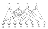
図2は、図1のパリティ検査行列H1に対応するタナーグラフを示す図である。 Figure 2 is a diagram illustrating a Tanner graph corresponding to the parity-check matrix H 1 of FIG. 1.
図2を参照すると、LDPC符号のタナーグラフは、8個の変数ノードx1(202)、x2(204)、x3(206)、x4(208)、x5(210)、x6(212)、x7(214)、及びx8(216)と4個の検査ノード(218、220、222、224)とを含む。 Referring to FIG. 2, a Tanner graph of an LDPC code includes eight variable nodes x 1 (202), x 2 (204), x 3 (206), x 4 (208), x 5 (210), x 6 (212), x 7 (214), and x 8 (216) and four check nodes (218, 220, 222, 224).
ここで、LDPC符号のパリティ検査行列H1のi番目の列及びj番目の行は、変数ノードxi及びj番目の検査ノードにマッピングされる。また、LDPC符号のパリティ検査行列H1のi番目の列及びj番目の行が相互に交差する地点での1の値、即ち、0でない値は、図2のタナーグラフ上で変数ノードxiとj番目の検査ノード間にエッジが存在することを意味する。 Here, the i th column and the j th row of the parity check matrix H 1 of the LDPC code are mapped to the variable node x i and the j th check node. Also, a value of 1 at the point where the i-th column and j-th row of the parity check matrix H 1 of the LDPC code intersect each other, that is, a non-zero value, is the variable node x i on the Tanner graph of FIG. Means that there is an edge between the j-th check node.
LDPC符号のタナーグラフにおいて、変数ノード及び検査ノードの次数(degree)は、各ノードに接続されているエッジの個数を意味し、これは、LDPC符号のパリティ検査行列で関連するノードに対応する列、又は行で0でないエントリーの個数と同一である。例えば、図2において、変数ノードx1(202)、x2(204)、x3(206)、x4(208)、x5(210)、x6(212)、x7(214)、及びx8(216)の次数は、それぞれ4、3、3、3、2、2、2、及び2であり、検査ノード218、220、222、及び224の次数は、それぞれ6、5、5、及び5である。また、図2の変数ノードに対応する図1のパリティ検査行列H1のそれぞれの列で0でないエントリーの個数は、上記した次数4、3、3、3、2、2、2、及び2と一致し、図2の検査ノードに対応する図1のパリティ検査行列H1のそれぞれの行で0でないエントリーの個数は、上記した次数6、5、5、及び5と一致する。
In a Tanner graph of an LDPC code, the degree of a variable node and a check node means the number of edges connected to each node, which is a column corresponding to a related node in the parity check matrix of the LDPC code. Or the number of non-zero entries in the row. For example, in FIG. 2, variable nodes x 1 (202), x 2 (204), x 3 (206), x 4 (208), x 5 (210), x 6 (212), x 7 (214), And x 8 (216) have orders of 4, 3, 3, 3, 2, 2, 2, and 2, respectively, and
LDPC符号のノードに対する次数分布(degree distribution)を示すために、次数がiである変数ノードの個数と変数ノードの総数との比率をfiとして定義し、次数がjである検査ノードの個数と検査ノード総数との比率をgjとして定義する。 To demonstrate the degree distribution (degree distribution) for a node of the LDPC code, defines the ratio of the total number of the number and variable nodes of the variable node degree is i as f i, and the number of check nodes degree-j The ratio with the total number of check nodes is defined as g j .
例えば、図1及び図2に対応するLDPC符号の場合には、f2=4/8、f3=3/8、f4=1/8、i≠2、3、4に対してfi=0であり、g5=3/4、g6=1/4、j≠5、6に対してgj=0である。LDPC符号の長さをN、即ち、列の個数をNとして定義し、行の個数をN/2として定義する場合、上述した次数分布を有する全パリティ検査行列で0でないエントリーの密度は、下記の数式(1)のように計算される。
For example, for the LDPC code corresponding to FIGS. 1 and 2, f 2 = 4/8,

上記数式(1)において、Nが増加するに従って、パリティ検査行列内の‘1’の密度は減少する。一般的に、LDPC符号について、符号語の長さNが0でないエントリーの密度に反比例するので、Nが大きいLDPC符号は、0でないエントリーの非常に低い密度を有する。LDPC符号の名称での用語“低密度(low−density)”は、上述した関係から由来する。 In Equation (1), as N increases, the density of ‘1’ in the parity check matrix decreases. In general, for LDPC codes, codeword length N is inversely proportional to the density of non-zero entries, so LDPC codes with large N have a very low density of non-zero entries. The term “low-density” in the name of the LDPC code is derived from the relationship described above.
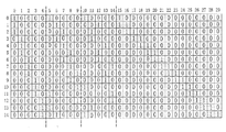
図3は、ヨーロッパデジタルブロードキャスト標準の中の1つであるDVB−S2(Digital Video Broadcasting−Satellite Transmission 2nd generation)で標準技術として採択されたLDPC符号を概略的に示す図である。
Figure 3 is a diagram schematically showing in is one DVB-S2 (Digital Video Broadcasting- Satellite
図3において、N1はLDPC符号語の長さを示し、K1は情報語の長さを示し、(N1−K1)はパリティ長さを提供する。また、M1及びqは、q=(N1−K1)/M1を満足する。好ましくは、K1/M1は、整数である。 In FIG. 3, N 1 indicates the length of the LDPC codeword, K 1 indicates the length of the information word, and (N 1 -K 1 ) provides the parity length. Further, M 1 and q satisfy q = (N 1 −K 1 ) / M 1 . Preferably, K 1 / M 1 is an integer.
図3を参照すると、パリティ検査行列でパリティ部分、即ち、K1番目の列から(N1−1)番目の列までの構成は、デュアル対角(dual diagonal)形態を有する。従って、パリティ部分に対応する列の次数の分布について、次数‘1’を有する最後の列を除いて、全ての列は、次数‘2’を有する。 Referring to FIG. 3, the parity part of the parity check matrix, that is, the configuration from the K 1 th column to the (N 1 −1) th column has a dual diagonal configuration. Therefore, with regard to the distribution of the degree of the column corresponding to the parity part, all the columns have the degree '2' except for the last column having the degree '1'.
パリティ検査行列において、情報語部分、即ち、0番目の列から(K1−1)番目の列までは、次の規則を用いて生成される。 In the parity check matrix, the information word part, that is, the 0th column to the (K 1 −1) th column is generated using the following rule.
〔規則1〕パリティ検査行列で情報語に対応するK1個の列をM1個の列で構成された複数のグループにグルーピングすることにより、トータルK1/M1個の列グループを生成する。各列グループに属している列を形成する方法は、下記の規則2に従う。
By grouping [Rule 1] K 1 piece corresponding to the information word in the parity-check matrix of the column into a plurality of groups composed of M 1 single row, to generate a total K 1 / M 1 column groups . The method of forming columns belonging to each column group follows the
〔規則2〕最初に、i(ここで、i=1、...、K1/M1)番目の列グループ内の各0番目の列での‘1’の位置を決定する。各i番目の列グループ内の0番目の列の次数をDiで示す場合、‘1’を有する行の位置を [Rule 2] First, the position of '1' in each 0th column in the i (where i = 1,..., K 1 / M 1 ) th column group is determined. When indicating the degree of the 0th column in each i th column group in D i, the positions of rows with '1'
![]()
![]()
![]()
![]()
上述した規則に従うと、i番目の列グループに属している列の次数が全てDiに等しいことが分かる。上述した規則に従ってパリティ検査行列に関する情報を格納しているDVB−S2 LDPC符号の構成を容易に理解するために、次のような具体的な例について説明する。 According to the above rules, it can be seen the degree of sequence belonging to the i-th column group are all equal to D i. In order to easily understand the configuration of the DVB-S2 LDPC code storing information related to the parity check matrix in accordance with the rules described above, the following specific example will be described.
具体的な一例として、N1=30、K1=15、M1=5、及びq=3であり、3個の列グループ内の0番目の列に対する‘1’を有する行の位置に関する情報の3つのシーケンスは、次のように表現することができる。ここで、このシーケンスは、“加重値−1位置シーケンス”と称する。 As a specific example, N 1 = 30, K 1 = 15, M 1 = 5, and q = 3, and information regarding the position of the row having '1' for the 0th column in the three column groups These three sequences can be expressed as follows. Here, this sequence is referred to as a “weight value-1 position sequence”.
各列グループ内の0番目の列の加重値−1位置シーケンスについて、説明の便宜上、列グループ別に対応する位置シーケンスだけを次の通りに表現することができる。例えば、
0 1 2
0 11 13
0 10 14
For the convenience of explanation, only the position sequence corresponding to each column group can be expressed as follows for the weighted value-1 position sequence of the 0th column in each column group. For example,
0 1 2
0 11 13
0 10 14
即ち、i番目のラインでこのi番目の“加重値−1位置シーケンス”は、i番目の列グループに対する‘1’を有する行の位置に関する情報を順次に示す。 That is, the i-th “weight-1 position sequence” in the i-th line sequentially indicates information regarding the position of the row having “1” for the i-th column group.
上述した具体的な例に対応する情報と規則1及び規則2とを用いてパリティ検査行列を構成することにより、図4のDVB−S2 LDPC符号と同一の概念を有するLDPC符号を生成することができる。
An LDPC code having the same concept as the DVB-S2 LDPC code of FIG. 4 can be generated by constructing a parity check matrix using information corresponding to the specific example described above and
規則1及び規則2に従って設計されたDVB−S2 LDPC符号が構造形状を用いて効率的に符号化することができることが知られている。パリティ検査行列に基づくDVB−S2を用いてLDPC符号化を実行する工程での各ステップを、次のような例を挙げて説明する。
It is known that DVB-S2 LDPC codes designed according to
以下の説明において、具体的な例として、N1=16200、K1=10800、M1=360、及びq=15を有するDVB−S2 LDPC符号を使用する符号化工程について説明する。説明の便宜のために、長さK1を有する情報語ビットは、 In the following description, an encoding process using a DVB-S2 LDPC code having N 1 = 16200, K 1 = 10800, M 1 = 360, and q = 15 will be described as a specific example. For convenience of explanation, an information word bit having a length K 1 is
![]()
![]()
![]()
![]()
〔ステップ1〕LDPC符号化器は、パリティビットを次のように初期化する。 [Step 1] The LDPC encoder initializes the parity bits as follows.
![]()
![]()
〔ステップ2〕LDPC符号化器は、格納されているパリティ検査行列を示すシーケンスの0番目の“加重値−1位置シーケンス”から列グループ内の‘1’が位置した行に関する情報を読み出す。
0 2084 1613 1548 1286 1460 3196 4297 2481 3369 3451 4620 2622
[Step 2] The LDPC encoder reads information on the row in which “1” is located in the column group from the 0th “weight value-1 position sequence” of the sequence indicating the stored parity check matrix.
0 2084 1613 1548 1286 1460 3196 4297 2481 3369 3451 4620 2622
LDPC符号化器は、上記読み出された情報及び第1の情報語ビットi0を用いて下記の数式(3)に従って特定のパリティビットpxをアップデートする。ここで、xは、 LDPC encoder updates particular parity bits p x in accordance with the following equation (3) using the information and the first information bits i 0 read above. Where x is
![]()
![]()
![]()
![]()
![]()
![]()
![]()
![]()
〔ステップ3〕LDPC符号化器は、i0の後の次の359個の情報語ビットim(ここで、m=1、2、...、359)に対して下記の数式(4)の値を求める。
{x+(m mod M1)×q} mod (N1−K1)
M1=360、m=1,2,...,359 ・・・数式(4)
上述した数式(4)において、xは、
[Step 3] The LDPC encoder performs the following equation (4) for the next 359 information word bits i m (where m = 1, 2,..., 359) after i 0. Find the value of.
{X + (m mod M 1 ) × q} mod (N 1 −K 1 )
M 1 = 360, m = 1, 2,. . . , 359 (4)
In the above equation (4), x is
![]()
![]()
次いで、LDPC符号化器は、上述した数式(4)で求められた値を用いて数式(3)と類似した動作を実行する。即ち、LDPC符号化器は、imに対して Next, the LDPC encoder performs an operation similar to Equation (3) using the value obtained in Equation (4) described above. That, LDPC encoder for i m
![]()
![]()
例えば、m=1の場合、即ち、i1に対して、LDPC符号化器は、下記の数式(5)で定義されるように、パリティビット For example, when m = 1, that is, for i 1 , the LDPC encoder performs parity bits as defined by Equation (5) below.
![]()
![]()
上述した数式(5)において、q=15である。LDPC符号化器は、m=1、2、...、359に対して上記のような工程を同様に実行する。 In the above formula (5), q = 15. The LDPC encoder has m = 1, 2,. . . 359, the above process is performed in the same manner.
〔ステップ4〕ステップ2と同様に、LDPC符号化器は、361番目の情報語ビットi360に対して1番目の加重値−1位置シーケンス [Step 4] Similar to step 2, the LDPC encoder performs the first weight value-1 position sequence on the 361st information word bit i 360 .
![]()
![]()
![]()
![]()
![]()
![]()
〔ステップ5〕LDPC符号化器は、それぞれの360個の情報語ビットを有する全てのグループに対してステップ2、3、及び4を反復する。
[Step 5] The LDPC encoder repeats
〔ステップ6〕LDPC符号化器は、最終的に数式(6)を用いてパリティビットを決定する。 [Step 6] The LDPC encoder finally determines parity bits using Equation (6).
![]()
![]()
数式(6)のパリティビットpiは、LDPC符号化が完了することにより得られたパリティビットである。 The parity bit p i in Expression (6) is a parity bit obtained by completing the LDPC encoding.
上述したように、DVB−S2は、ステップ1からステップ6までの工程で説明したように符号化を行う。
As described above, DVB-S2 performs encoding as described in the steps from
LDPC符号を実際の通信システムに適用するためには、LDPC符号は、通信システムで要求されるデータ送信量に適合するように設計されなければならない。特に、ハイブリッド自動再送要求(Hybrid Automatic Retransmission Request:HARQ)方式及び適応型変調及び符号化(Adaptive Modulation and Coding:AMC)方式を適用する適応型通信システムだけでなく、様々なブロードキャストサービスをサポートする通信システムでも、システムの要求に従って様々なデータ送信量をサポートするために様々な符号語の長さを有するLDPC符号が必要とされる。 In order to apply the LDPC code to an actual communication system, the LDPC code must be designed to match the amount of data transmission required in the communication system. In particular, communication that supports various broadcast services as well as an adaptive communication system that applies a Hybrid Automatic Retransmission Request (HARQ) method and an adaptive modulation and coding (AMC) method. The system also requires LDPC codes with different codeword lengths to support different data transmissions according to system requirements.
しかし、上述したように、DVB−S2システムで使用されるLDPC符号は、その制限された使用により2種類の符号語の長さのみを有し、LDPC符号の各タイプは、独立したパリティ検査行列を必要とする。このような理由で、システムの拡張性及び柔軟性を増加させるために様々な符号語の長さをサポートする方法が必要である。特に、DVB−S2システムでは、シグナリング情報の送信のために数百から数千ビットのデータ送信が必要である。しかし、DVB−S2 LDPC符号の長さには、16200及び64800のみが使用可能であるため、様々な符号語の長さをサポートする必要があるという問題がある。しかし、LDPC符号の各符号語の長さに対して独立したパリティ検査行列を格納することは、メモリ効率性を減少させるため、新たなパリティ検査行列を設計せず、既存のパリティ検査行列から様々な符号語の長さを効率的にサポートすることができる方式が要求されている。 However, as described above, the LDPC code used in the DVB-S2 system has only two codeword lengths due to its limited use, and each type of LDPC code has an independent parity check matrix. Need. For this reason, there is a need for a method that supports various codeword lengths to increase system scalability and flexibility. In particular, in the DVB-S2 system, data transmission of hundreds to thousands of bits is necessary for transmission of signaling information. However, since only DVB-S2 LDPC codes of 16200 and 64800 can be used, there is a problem that it is necessary to support various codeword lengths. However, storing an independent parity check matrix for the length of each codeword of the LDPC code reduces memory efficiency, so a new parity check matrix is not designed and a variety of existing parity check matrices are used. There is a need for a scheme that can efficiently support long codeword lengths.
高次変調方式が2位相偏移変調(BPSK)又は4位相偏移変調(QPSK)だけを使用する通信システムに適用される場合とは異なり、高次変調方式が様々な符号語の長さを有するLDPC符号を要求する通信システムで使用される場合に、高次変調シンボルに含まれたビットの信頼度が異なることに留意すべきである。 Unlike when higher order modulation schemes are applied to communication systems that use only binary phase shift keying (BPSK) or quadrature phase shift keying (QPSK), higher order modulation schemes have different codeword lengths. It should be noted that the reliability of the bits included in the higher-order modulation symbols is different when used in a communication system that requires an LDPC code having.
高次変調方式での信頼度差を証明するために、以下では、通信システムで一般に使用される高次変調方式である直交振幅変調(QAM)方式を適用する場合の信号コンステレーションについて説明する。QAMで変調されたシンボルは、実数部及び虚数部を含み、様々な変調シンボルは、各実数部及び虚数部の大きさ及び符号を異ならせることにより生成することができる。QAMは、QAM特性の詳細をより明確に提供するためにQPSK変調方式と共に説明する。 In order to prove the reliability difference in the high-order modulation scheme, a signal constellation when applying a quadrature amplitude modulation (QAM) scheme, which is a high-order modulation scheme generally used in a communication system, will be described below. A symbol modulated by QAM includes a real part and an imaginary part, and various modulation symbols can be generated by changing the size and sign of each real part and imaginary part. QAM will be described with a QPSK modulation scheme to provide more details of QAM characteristics more clearly.
図5Aは、従来のQPSK変調方式の信号コンステレーションを概略的に示す図である。 FIG. 5A is a diagram schematically showing a signal constellation of a conventional QPSK modulation method.
図5Aを参照すると、y0は実数部の符号を決定し、y1は虚数部の符号を決定する。即ち、y0=0の場合、実数部の符号は正(+)であり、y0=1の場合、実数部の符号は負(−)である。また、y1=0の場合、虚数部の符号は正(+)であり、y1=1の場合、虚数部の符号は負(−)である。y0及びy1が実数部及び虚数部の各符号を示す符号表示ビットであるので、y0及びy1のエラー発生確率は同一である。従って、QPSK変調方式の場合、1つの変調信号に対応する(y0,y1)ビットの信頼度は同一である。ここで、y0,q及びy1,qで表記した時、2番目の下付き文字インデックスqは、変調信号に含まれたビットのq番目の出力を示す。 Referring to FIG. 5A, y 0 determines the sign of the real part and y 1 determines the sign of the imaginary part. That is, when y 0 = 0, the sign of the real part is positive (+), and when y 0 = 1, the sign of the real part is negative (−). Further, when y 1 = 0, the sign of the imaginary part is positive (+), and when y 1 = 1, the sign of the imaginary part is negative (−). Since y 0 and y 1 are sign indication bits indicating the signs of the real part and the imaginary part, the error occurrence probabilities of y 0 and y 1 are the same. Therefore, in the case of the QPSK modulation method, the reliability of (y 0 , y 1 ) bits corresponding to one modulation signal is the same. Here, when expressed as y 0, q and y 1, q , the second subscript index q indicates the q-th output of the bit included in the modulation signal.
図5Bは、従来の16−QAM変調方式の信号コンステレーションを概略的に示す図である。 FIG. 5B is a diagram schematically showing a signal constellation of a conventional 16-QAM modulation method.
図5Bを参照すると、(y0、y1、y2、y3)は、1つの変調信号のビットに対応する。特に、ビットy0及びy2は、それぞれ実数部の符号及び大きさを決定し、ビットy1及びy3は、それぞれ虚数部の符号及び大きさを決定する。即ち、y0及びy1は、変調信号の実数部及び虚数部の符号を決定し、y2及びy3は、変調信号の実数部及び虚数部の大きさを決定する。変調された信号の符号の識別がこの変調された信号の大きさの識別より更に容易であるために、エラー発生確率においては、y2及びy3がy0及びy1より高い。従って、ビットのエラーが発生しない確率(即ち、信頼度)の観点では、y0=y1>y2=y3の順序となる。即ち、QPSKとは異なり、QAM変調信号に含まれたビット(y0、y1、y2、y3)は、相互に異なる信頼度を有する。 Referring to FIG. 5B, (y 0 , y 1 , y 2 , y 3 ) corresponds to one modulated signal bit. In particular, bits y 0 and y 2 determine the sign and size of the real part, respectively, and bits y 1 and y 3 determine the sign and size of the imaginary part, respectively. That is, y 0 and y 1 determine the sign of the real part and imaginary part of the modulation signal, and y 2 and y 3 determine the magnitude of the real part and imaginary part of the modulation signal. Since the identification of the code of the modulated signal is easier than the identification of the magnitude of this modulated signal, y 2 and y 3 are higher than y 0 and y 1 in the error probability. Therefore, from the viewpoint of the probability that no bit error occurs (that is, reliability), the order is y 0 = y 1 > y 2 = y 3 . That is, unlike QPSK, bits (y 0 , y 1 , y 2 , y 3 ) included in the QAM modulated signal have different reliability.
16−QAM変調方式において、信号を構成する4個のビットの中で2個のビットは、信号の実数部及び虚数部の符号を決定し、残りの2個のビットは、信号の実数部及び虚数部の大きさを決定すればよい。従って、(y0、y1、y2、y3)の順序及び各ビットの役割は、変わる可能性がある。 In the 16-QAM modulation scheme, two of the four bits constituting a signal determine the sign of the real part and the imaginary part of the signal, and the remaining two bits are the real part of the signal and What is necessary is just to determine the magnitude | size of an imaginary part. Therefore, the order of (y 0 , y 1 , y 2 , y 3 ) and the role of each bit may change.
図5Cは、従来の64−QAM変調方式の信号コンステレーションを概略的に示す図である。 FIG. 5C is a diagram schematically illustrating a signal constellation of a conventional 64-QAM modulation method.
1つの変調信号のビットに対応する(y0、y1、y2、y3、y4、y5)の中で、ビットy0、y2、及びy4は、実数部の大きさ及び符号を決定し、y1、y3、及びy5は、虚数部の大きさ及び符号を決定する。この時、y0及びy1は、それぞれ実数部及び虚数部の符号を決定し、y2とy4との組合せ及びy3とy5との組合せは、それぞれ実数部及び虚数部の大きさを決定する。上述したように、変調された信号の符号の識別がこの変調された信号の大きさの識別より更に容易であるために、y0及びy1の信頼度は、y2、y3、y4、及びy5の信頼度より高い。 Among (y 0 , y 1 , y 2 , y 3 , y 4 , y 5 ) corresponding to the bits of one modulation signal, the bits y 0 , y 2 , and y 4 are the size of the real part and The sign is determined, and y 1 , y 3 , and y 5 determine the size and sign of the imaginary part. At this time, y 0 and y 1 determine the sign of the real part and the imaginary part, respectively, and the combination of y 2 and y 4 and the combination of y 3 and y 5 are the sizes of the real part and the imaginary part, respectively. To decide. As mentioned above, the reliability of y 0 and y 1 is y 2 , y 3 , y 4 because the identification of the sign of the modulated signal is easier than the identification of the magnitude of the modulated signal. , and higher than the reliability of the y 5.
ビットy2及びy3は、変調されたシンボルの大きさが4より大きいか又は小さいかに基づいて決定され、ビットy4及びy5は、変調されたシンボルの大きさが2を基準にして4又は0に近いかに従って決定されるか、或いは、6を基準にして4又は8に近いかに従って決定される。従って、y2及びy3により決定される範囲の大きさは4であり、y4及びy5により決定される範囲の大きさは2である。従って、y2及びy3の信頼度がy4及びy5の信頼度より高い。その結果、各ビットのエラーが発生しない確率(即ち、信頼度)の観点では、y0=y1>y2=y3>y4=y5の順序となる。 Bits y 2 and y 3 are determined based on whether the modulated symbol size is greater than or less than 4, and bits y 4 and y 5 are based on a modulated symbol size of 2 It is determined according to whether it is close to 4 or 0, or is determined according to whether it is close to 4 or 8 with reference to 6. Therefore, the size of the range determined by y 2 and y 3 is 4, and the size of the range determined by y 4 and y 5 is 2. Therefore, the reliability of y 2 and y 3 is higher than the reliability of y 4 and y 5. As a result, the order of y 0 = y 1 > y 2 = y 3 > y 4 = y 5 is satisfied from the viewpoint of the probability that an error of each bit does not occur (that is, reliability).
64−QAM変調方式において、信号を構成する6個のビットの中で2個のビットは、信号の実数部及び虚数部の符号を決定し、4個のビットは、信号の実数部及び虚数部の大きさを決定すればよい。従って、(y0、y1、y2、y3、y4、y5)の順序及び各ビットの役割は、変わる可能性がある。また、256−QAM又はそれ以上の信号コンステレーションの場合にも、上述したものと同一の方式で変調信号を構成するビットの役割及び信頼度が異なる。従って、これに関する詳細な説明は省略する。 In 64-QAM modulation, two of the six bits that make up a signal determine the sign of the real and imaginary parts of the signal, and four bits are the real and imaginary parts of the signal. The size of can be determined. Therefore, the order of (y 0 , y 1 , y 2 , y 3 , y 4 , y 5 ) and the role of each bit may change. Also in the case of a signal constellation of 256-QAM or higher, the role and reliability of the bits constituting the modulation signal in the same manner as described above are different. Therefore, the detailed description regarding this is abbreviate | omitted.
要約すると、BPSK又はQPSK変調方式では、シンボルに含まれたビットの信頼度が同一であり、短縮又はパンクチャーリングを適用したLDPC符号語で各符号語ビットの信頼度も同一であるため、短縮及びパンクチャーリングパターンを決定する際に変調方式を考慮する必要はない。しかし、16−QAM、64−QAM、256−QAMのような高次変調方式では、シンボルに含まれたビットの役割及び信頼度が異なるために、変調方式及び信号コンステレーション/ビットマッピング(信号コンステレーション上のビットマッピング)方式が決定された際、短縮又はパンクチャーリングを適用した後のLDPC符号語での各符号語ビットの信頼度が短縮又はパンクチャーリングを適用する前のそれとは異なることがあるという問題がある。 In summary, in the BPSK or QPSK modulation scheme, the reliability of the bits included in the symbol is the same, and the reliability of each codeword bit is the same in the LDPC codeword to which the shortening or puncturing is applied. It is not necessary to consider the modulation scheme when determining the puncturing pattern. However, in higher-order modulation schemes such as 16-QAM, 64-QAM, and 256-QAM, the role and reliability of the bits included in the symbols are different, so the modulation scheme and signal constellation / bit mapping (signal constellation) are different. When the bit mapping method is determined, the reliability of each codeword bit in the LDPC codeword after applying shortening or puncturing is different from that before applying shortening or puncturing. There is a problem that there is.
従って、高次変調方式に基づく短縮又はパンクチャーリングを用いてLDPC符号を生成する装置及び方法が要求される。 Accordingly, there is a need for an apparatus and method for generating an LDPC code using shortening or puncturing based on a higher-order modulation scheme.
本発明は、上記従来の問題点に鑑みてなされたものであって、本発明の目的は、通信システムにおいて高次変調を考慮して決定された短縮又はパンクチャーリングを用いて与えられたLDPC符号から異なる符号語の長さを有するLDPC符号を生成し、この生成されたLDPC符号を用いてチャネルの符号化及び復号化を行う符号化及び復号化方法並びにその装置を提供することにある。 The present invention has been made in view of the above-described conventional problems, and an object of the present invention is to provide LDPC given using shortening or puncturing determined in consideration of higher-order modulation in a communication system. An object of the present invention is to provide an encoding and decoding method and apparatus for generating LDPC codes having different codeword lengths from the codes, and performing channel encoding and decoding using the generated LDPC codes.
また、本発明の他の目的は、LDPC符号を使用する通信システムにおいてDVB−S2構成を考慮して最適の性能を提供するチャネル符号化及び復号化方法並びにその装置を提供することにある。 Another object of the present invention is to provide a channel coding and decoding method and apparatus for providing optimum performance in consideration of the DVB-S2 configuration in a communication system using an LDPC code.
上記目的を達成するために、本発明の一態様によれば、低密度パリティ検査(LDPC)符号を使用するシステムにおけるチャネル符号化方法を提供する。前記方法は、情報ビットを複数のビットグループに区分するステップと、短縮される情報ビットの数を決定するステップと、前記決定された短縮される情報ビットの数に基づいて短縮されるビットグループの数を決定するステップと、予め定められたビットグループの順序に従って前記決定されたビットグループの情報ビットを短縮するステップと、前記短縮された情報ビットを符号化するステップと、を有し、情報ビットの長さが7200であり、符号語の長さが16200である場合に、前記予め定められたビットグループの順序は、18、17、16、15、14、13、12、11、4、10、9、8、7、3、2、1、6、5、19、及び0である。 To achieve the above object, according to an aspect of the present invention, a channel coding method in a system using a low density parity check (LDPC) code is provided. The method includes partitioning information bits into a plurality of bit groups; determining a number of information bits to be shortened; and reducing a bit group to be shortened based on the determined number of information bits to be shortened. Determining a number; shortening information bits of the determined bit group according to a predetermined order of bit groups; and encoding the shortened information bits. Is 7200 and the codeword length is 16200, the predetermined order of the bit groups is 18, 17, 16, 15, 14, 13, 12, 11, 4, 10 , 9, 8, 7, 3, 2, 1, 6, 5, 19, and 0.
本発明の他の態様によれば、低密度パリティ検査(LDPC)符号を使用するシステムにおけるチャネル符号化装置を提供する。前記装置は、情報ビットを複数のビットグループに区分し、短縮される情報ビットの数を決定し、前記決定された短縮される情報ビットの数に基づいて短縮されるビットグループの数を決定し、予め定められたビットグループの順序に従って前記決定されたビットグループの情報ビットを短縮する短縮パターン適用部と、前記短縮された情報ビットを符号化する符号化器と、を備え、情報ビットの長さが7200であり、符号語の長さが16200である場合に、前記予め定められたビットグループの順序は、18、17、16、15、14、13、12、11、4、10、9、8、7、3、2、1、6、5、19、及び0である。 According to another aspect of the present invention, a channel coding apparatus in a system using a low density parity check (LDPC) code is provided. The apparatus divides information bits into a plurality of bit groups, determines the number of information bits to be shortened, and determines the number of bit groups to be shortened based on the determined number of information bits to be shortened. A shortening pattern application unit that shortens the information bits of the determined bit group according to a predetermined order of the bit groups, and an encoder that encodes the shortened information bits. Is 7200 and the codeword length is 16200, the predetermined bit group order is 18, 17, 16, 15, 14, 13, 12, 11, 4, 10, 9 , 8, 7, 3, 2, 1, 6, 5, 19, and 0.
本発明の他の態様によれば、低密度パリティ検査(LDPC)符号を使用するシステムにおけるチャネル復号化方法を提供する。前記方法は、受信された信号を復調するステップと、短縮された情報ビットの位置を決定するステップと、前記決定された短縮された情報ビットの位置を考慮して前記復調された信号を復号化するステップと、を有し、前記短縮された情報ビットの位置を決定するステップは、短縮された情報ビットの数を決定するステップと、前記決定された短縮された情報ビットの数に基づいて短縮されたビットグループの数を決定するステップと、予め定められたビットグループの順序を取得するステップと、を有し、情報ビットの長さが7200であり、符号語の長さが16200である場合に、前記予め定められたビットグループの順序は、18、17、16、15、14、13、12、11、4、10、9、8、7、3、2、1、6、5、19、及び0である。 According to another aspect of the present invention, a channel decoding method in a system using a low density parity check (LDPC) code is provided. The method comprises: demodulating a received signal; determining a position of a shortened information bit; and decoding the demodulated signal in consideration of the determined position of the shortened information bit. Determining the position of the shortened information bits, determining the number of shortened information bits, and shortening based on the determined number of shortened information bits. A step of determining the number of assigned bit groups and a step of obtaining a predetermined order of bit groups, wherein the information bit length is 7200 and the codeword length is 16200 In addition, the order of the predetermined bit groups is 18, 17, 16, 15, 14, 13, 12, 11, 4, 10, 9, 8, 7, 3, 2, 1, 6, 5, 19 , Beauty is 0.
本発明の他の態様によれば、低密度パリティ検査(LDPC)符号を使用するシステムにおけるチャネル復号化装置を提供する。前記装置は、受信された信号を復調する復調器と、短縮された情報ビットの位置を決定する短縮パターン決定部と、前記決定された短縮された情報ビットの位置を考慮して前記復調された信号を復号化する復号化器と、を備え、前記短縮された情報ビットの位置は、短縮された情報ビットの数を決定し、前記決定された短縮された情報ビットの数に基づいて短縮されたビットグループの数を決定し、予め定められたビットグループの順序を取得することにより決定され、情報ビットの長さが7200であり、符号語の長さが16200である場合に、前記予め定められたビットグループの順序は、18、17、16、15、14、13、12、11、4、10、9、8、7、3、2、1、6、5、19、及び0である。 According to another aspect of the present invention, a channel decoding apparatus in a system using a low density parity check (LDPC) code is provided. The apparatus includes a demodulator that demodulates a received signal, a shortened pattern determining unit that determines a position of a shortened information bit, and the demodulated in consideration of the determined position of the shortened information bit. A decoder for decoding a signal, wherein the position of the shortened information bits is determined based on the determined number of shortened information bits, determining the number of shortened information bits The predetermined number of bit groups is determined and the predetermined bit group order is obtained, and when the information bit length is 7200 and the codeword length is 16200, the predetermined bit group order is determined. The order of the given bit groups is 18, 17, 16, 15, 14, 13, 12, 11, 4, 10, 9, 8, 7, 3, 2, 1, 6, 5, 19, and 0 .
本発明は、高次変調及びLDPC符号を使用する通信システムにおいて所定のパリティ検査行列に関する情報を用いて異なる符号語の長さを有する個別のLDPC符号を生成することができるという長所がある。 The present invention has an advantage in that individual LDPC codes having different codeword lengths can be generated using information on a predetermined parity check matrix in a communication system using higher-order modulation and LDPC codes.
また、本発明の実施形態は、変調方式に従って異なる短縮パターンを用いて短縮を行うことができるという長所がある。 In addition, the embodiment of the present invention has an advantage that shortening can be performed using different shortening patterns according to the modulation scheme.
本発明の他の目的、利点、及び顕著な特徴は、添付の図面及び本発明の実施形態からなされた以下の詳細な説明から、この分野の当業者に明確になるはずである。 Other objects, advantages and salient features of the present invention will become apparent to those skilled in the art from the accompanying drawings and the following detailed description made from the embodiments of the present invention.
添付の図面を参照した下記の説明は、特許請求の範囲の記載及びこれと均等なものの範囲内で定められるような本発明の実施形態の包括的な理解を助けるために提供する。これは、この理解を助けるための様々な特定の詳細を含むが、唯一つの実施形態にすぎない。従って、本発明の範囲及び趣旨を逸脱することなく、ここに説明した実施形態の様々な変更及び修正が可能であるということは、当該技術分野における通常の知識を有する者には明らかである。また、明瞭性と簡潔性の観点から、当業者に良く知られている機能や構成に関する具体的な説明は、省略する。 The following description with reference to the accompanying drawings is provided to assist in a comprehensive understanding of embodiments of the invention as defined in the appended claims and their equivalents. This includes various specific details to aid this understanding, but is only one embodiment. Accordingly, it will be apparent to those skilled in the art that various modifications and variations can be made to the embodiments described herein without departing from the scope or spirit of the invention. In addition, from the viewpoints of clarity and conciseness, detailed descriptions of functions and configurations well known to those skilled in the art are omitted.
また、次の説明及び請求項に使用する用語及び単語は、辞典的意味に限定されるものではなく、発明者により本発明の理解を明確且つ一貫性のあるようにするために使用する。従って、本発明の実施形態の説明が単に実例を提供するためのものであり、特許請求の範囲とこれと均等なものに基づいて定義される発明を限定する目的で提供するものでないことは、本発明の技術分野における通常の知識を持つ者には明らかである。 Also, the terms and words used in the following description and claims are not limited to the dictionary meaning, but are used by the inventor to make the understanding of the present invention clear and consistent. Accordingly, the description of the embodiments of the present invention is merely provided for illustrative purposes, and is not intended to limit the invention defined based on the claims and their equivalents. It will be apparent to those of ordinary skill in the art of the present invention.
本発明の実施形態の下記の説明は、特定の構造形状(structural shape)のLDPC符号のパリティ検査行列を用いて高次変調に適合した様々な符号語の長さを有するLDPC符号をサポートする方法を提案する。また、本発明の実施形態の説明は、特定の構造形状のLDPC符号を使用する通信システムにおいて、高次変調方式に従って様々な符号語の長さをサポートする装置及びその制御方法を提案する。特に、本発明の実施形態の説明は、与えられたLDPC符号のパリティ検査行列を用いて与えられたLDPC符号より小さいLDPC符号を生成する方法及びその装置を提案する。 The following description of embodiments of the present invention describes a method for supporting LDPC codes having various codeword lengths adapted to higher-order modulation using a parity check matrix of LDPC codes having a specific structure shape. Propose. In addition, the description of the embodiment of the present invention proposes an apparatus that supports various codeword lengths according to a higher-order modulation scheme and a control method thereof in a communication system using an LDPC code having a specific structure. In particular, the embodiments of the present invention propose a method and apparatus for generating an LDPC code smaller than a given LDPC code using a parity check matrix of the given LDPC code.
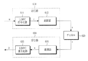
図6は、LDPC符号を使用する通信システムの送受信器の構成を示すブロック図である。 FIG. 6 is a block diagram illustrating a configuration of a transceiver of a communication system using an LDPC code.
図6を参照すると、メッセージuは、受信器630に送信される前に送信器610内のLDPC符号化器611に入力される。LDPC符号化器611は、入力されたメッセージuを符号化し、この符号化した信号cを変調器613に出力する。変調器613は、符号化した信号cを変調した後に、この変調した信号sを無線チャネル620を介して受信器630に送信する。受信器630内の復調器631は、受信した信号rを復調した後に、この復調した信号xをLDPC復号化器633に出力する。LDPC復号化器633は、復調信号xを復号化した後に、無線チャネル620を介して受信したデータに基づいてメッセージの推定値
Referring to FIG. 6, the message u is input to the
![]()
![]()
LDPC符号化器611は、所定の方式を用いて通信システムにより要求される符号語の長さに従ってパリティ検査行列を生成する。特に、本発明の一実施形態によると、LDPC符号化器611は、付加的な格納情報を別途に必要とせずにLDPC符号を用いて様々な符号語の長さをサポートすることができる。
The
本発明の一実施形態によると、与えられたLDPC符号から様々な符号語の長さを取得する方法は、短縮法(shortening)及びパンクチャーリング法(puncturing)を使用する。符号化率又は符号語の長さに従って短縮又はパンクチャーリングをLDPC符号に適用することにより性能を最適化する方法が現在知られている。しかし、殆どの場合、短縮及びパンクチャーリングパターンを決定する既知の方法が2位相偏移変調(BPSK)又は4位相偏移変調(QPSK)だけを考慮して最適化工程を実行するため、最適化された短縮及び/又はパンクチャーリングパターンは与えられたLDPC符号に対して1つだけ存在することができる。 According to an embodiment of the present invention, a method for obtaining various codeword lengths from a given LDPC code uses a shortening method and a puncturing method. Methods are currently known for optimizing performance by applying shortening or puncturing to LDPC codes according to code rate or codeword length. However, in most cases, the known method of determining shortening and puncturing patterns performs the optimization process taking into account only two-phase shift keying (BPSK) or four-phase shift keying (QPSK). There can be only one normalized shortening and / or puncturing pattern for a given LDPC code.
しかし、信号コンステレーション/ビットマッピング方式が高次変調を用いて決定された場合の最適化されたパンクチャーリング及び短縮パターンは、BPSK又はQPSK変調方式のそれとは異なることがある。 However, the optimized puncturing and shortening pattern when the signal constellation / bit mapping scheme is determined using higher order modulation may differ from that of the BPSK or QPSK modulation scheme.
BPSK又はQPSK変調方式において、シンボルに含まれたビットの信頼度が同一であるため、短縮又はパンクチャーリングを適用した後のLDPC符号語で各符号語ビットの信頼度も同一である。その結果、短縮及びパンクチャーリングパターンを決定する工程で変調方式を考慮する必要はない。しかし、上述したように、16−QAM、64−QAM、及び256−QAMのような高次変調方式では、シンボルに含まれたビットの信頼度が異なるために、変調方式及び信号コンステレーション/ビットマッピング方式が決定された場合、短縮又はパンクチャーリングを適用した後のLDPC符号語での各符号語ビットの信頼度が短縮又はパンクチャーリングを適用する前のそれとは異なることがある。 In the BPSK or QPSK modulation scheme, since the reliability of the bits included in the symbol is the same, the reliability of each codeword bit is the same in the LDPC codeword after the shortening or puncturing is applied. As a result, it is not necessary to consider the modulation scheme in the process of determining shortening and puncturing patterns. However, as described above, in higher-order modulation schemes such as 16-QAM, 64-QAM, and 256-QAM, the reliability of bits included in symbols is different, so that the modulation scheme and signal constellation / bit are different. If the mapping scheme is determined, the reliability of each codeword bit in the LDPC codeword after applying shortening or puncturing may be different from that before applying shortening or puncturing.
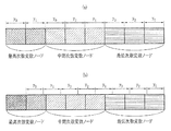
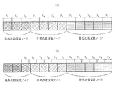
図7の(a)、図7の(b)、図8の(a)、及び図8の(b)は、変調方式がそれぞれ16−QAM及び64−QAMである時、LDPC符号語で変数ノードの次数に従ってシンボルにマッピングされるビットマッピングの例を示す図である。特に、図7の(a)は、16−QAM変調方式で信号コンステレーション/ビットマッピングの例を示す図であり、図7の(b)は、16−QAM変調方式で短縮による信号コンステレーション/ビットマッピングの変化の例を示す図である。説明の便宜上、ここで、LDPC符号語は、8個又は12個の部分ブロックに区分される。 7 (a), 7 (b), 8 (a), and 8 (b) are LDPC codeword variables when the modulation scheme is 16-QAM and 64-QAM, respectively. It is a figure which shows the example of the bit mapping mapped to a symbol according to the order of a node. In particular, FIG. 7A is a diagram illustrating an example of signal constellation / bit mapping in the 16-QAM modulation scheme, and FIG. 7B is a diagram illustrating signal constellation / bit mapping by shortening in the 16-QAM modulation scheme. It is a figure which shows the example of a change of bit mapping. For convenience of explanation, the LDPC codeword is divided into 8 or 12 partial blocks.
図7の(a)を参照すると、y0及びy1は、それぞれ16−QAMシンボルで実数部及び虚数部の符号を決定する信頼度が高いビットを意味する。即ち、ビット間の信頼度関係は、y0=y1>y2=y3である。図7の(a)において、最高次数変数ノードに対応するLDPC符号語ビット部分にはy1及びy3がマッピングされるため、この最高次数変数ノードの中の1/2は、信頼度が高い部分にマッピングされ、残りの1/2は、信頼度が低い部分に接続される。 Referring to FIG. 7A, y 0 and y 1 mean highly reliable bits that determine the sign of the real part and the imaginary part in a 16-QAM symbol, respectively. That is, the reliability relationship between bits is y 0 = y 1 > y 2 = y 3 . In FIG. 7A, since y 1 and y 3 are mapped to the LDPC codeword bit part corresponding to the highest order variable node, ½ of the highest order variable node has high reliability. The remaining half is connected to the part with low reliability.
図7の(b)に示すように、最高次数変数ノードの中の半分が短縮されたと仮定すると、短縮されない最高次数変数ノードに対応するシンボルビットが短縮されたLDPC符号語で考慮される場合、この最高次数変数ノードの7/8は、y3にマッピングされ、残りの1/8は、y1にマッピングされる。即ち、ビット率は、短縮前のそれとは非常に異なる。 As shown in FIG. 7 (b), assuming that half of the highest order variable nodes are shortened, if the symbol bits corresponding to the unordered highest order variable nodes are considered in the shortened LDPC codeword, 7/8 of the highest degree variable node is mapped to y 3, the remaining 1/8 is mapped to y 1. That is, the bit rate is very different from that before shortening.
同様に、図8の(a)は、64−QAM変調方式で信号コンステレーション/ビットマッピングの例を示す図であり、図8の(b)は、64−QAM変調方式で短縮による信号コンステレーション/ビットマッピングの変化の例を示す図である。 Similarly, FIG. 8A is a diagram showing an example of signal constellation / bit mapping in the 64-QAM modulation scheme, and FIG. 8B is a signal constellation by shortening in the 64-QAM modulation scheme. FIG. 10 is a diagram illustrating an example of changes in bit mapping.
図8の(a)において、シンボルに含まれたビット間の信頼度関係は、y0=y1>y2=y3>y4=y5である。この場合、LDPC符号語で最高次数を有する変数ノードの1/3が最低の信頼度ビットy5にマッピングされることが分かる。しかし、図8の(b)に示すように、最高次数変数ノードの中の2/3が短縮された場合には、短縮されない残りの最高次数変数ノードの5/6が最低の信頼度ビットy5にマッピングされ、これにより、ビット率が短縮される前のそれとは異なることが分かる。 In FIG. 8A, the reliability relationship between the bits included in the symbol is y 0 = y 1 > y 2 = y 3 > y 4 = y 5 . In this case, it can be seen that one-third of the variable nodes having the highest degree in the LDPC codeword are mapped to the lowest reliability bits y 5. However, as shown in FIG. 8B, when 2/3 of the highest order variable nodes are shortened, 5/6 of the remaining highest order variable nodes that are not shortened have the lowest reliability bit y. 5 is mapped to, thereby, different can be seen from that before the bit rate is reduced.
上述したように、高次変調方式及び信号コンステレーション/ビットマッピング方式が与えられたLDPC符号に対して固定されている場合、BPSK又はQPSK変調方式で使用された短縮又はパンクチャーリングパターンは、変調シンボルの各ビットにマッピングされるLDPC符号語ビットの比率が短縮技術に従って非常に異なるために適合しない可能性がある。 As described above, when a higher-order modulation scheme and a signal constellation / bit mapping scheme are fixed for a given LDPC code, the shortening or puncturing pattern used in the BPSK or QPSK modulation scheme is modulated. It may not fit because the ratio of LDPC codeword bits mapped to each bit of the symbol is very different according to the shortening technique.
また、LDPC符号の場合において、最適化されたLDPC符号のパリティ検査行列の次数分布が変調方式に従って非常に異なることがよく知られている。即ち、BPSK又はQPSK変調方式に最適化されたLDPC符号の次数分布と16−QAM、64−QAM、及び256−QAMに最適化されたLDPC符号の次数分布とは全て異なる。 In the case of an LDPC code, it is well known that the degree distribution of the parity check matrix of the optimized LDPC code is very different according to the modulation scheme. That is, the order distribution of the LDPC code optimized for the BPSK or QPSK modulation scheme and the order distribution of the LDPC code optimized for 16-QAM, 64-QAM, and 256-QAM are all different.
同様の理由から、1つの次数分布を有するLDPC符号が与えられたと仮定した場合、最適化された短縮又はパンクチャーリングパターンが高次変調方式に従って異なることが自明である。従って、LDPC符号の最適化された短縮又はパンクチャーリングパターンを求めるためには、適用する変調方式を考慮して短縮パターンを決定しなければならない。 For the same reason, it is obvious that the optimized shortening or puncturing pattern differs according to the higher order modulation scheme, assuming that an LDPC code having one degree distribution is given. Therefore, in order to obtain an optimized shortening or puncturing pattern of the LDPC code, the shortening pattern must be determined in consideration of the modulation scheme to be applied.
変調方式を考慮した短縮又はパンクチャーリングパターンを決定する方法を説明する前に先ず短縮法について説明する。ここで使用される‘短縮法’は、LDPC符号化を行うことにより与えられた特定のパリティ検査行列からLDPC符号語を生成した後に、LDPC符号語の特定の部分を実質的に送信しない方法を意味する。以下、短縮法の更なる理解を助けるために、図3に示したDVB−S2 LDPC符号のパリティ検査行列についてより詳細に説明する。 Before describing a method for determining a shortening or puncturing pattern in consideration of a modulation scheme, the shortening method will be described first. The 'shortening method' used here is a method in which a specific part of an LDPC codeword is not substantially transmitted after an LDPC codeword is generated from a specific parity check matrix given by performing LDPC coding. means. Hereinafter, the parity check matrix of the DVB-S2 LDPC code shown in FIG. 3 will be described in more detail to help further understanding of the shortening method.
図3に示したDVB−S2 LDPC符号のパリティ検査行列について、その全長がN1であり、長さがK1である情報語ビット For the parity check matrix of the DVB-S2 LDPC code shown in FIG. 3, the information word bits whose total length is N 1 and whose length is K 1
![]()
![]()
![]()
![]()
即ち、i0からiNs−1までのNs個の情報語ビットに対する値を0に制限することにより、短縮技術は、図3に示したDVB−S2 LDPC符号のパリティ検査行列でNs個の先頭列を実質的に使用しないものと同一の効果を得ることができる。‘短縮法’という用語は、上述した制限動作から由来する。従って、本発明で短縮を適用することは、短縮された情報語ビットの値を0として見なすことを意味する。 In other words, by limiting values for Ns pieces of information bits from i 0 to i Ns-1 to 0, the shortening technique, the Ns first in the parity-check matrix of the DVB-S2 LDPC code shown in FIG. 3 The same effect can be obtained as that using substantially no columns. The term 'shortening method' comes from the limiting action described above. Therefore, applying the shortening in the present invention means that the value of the shortened information word bit is regarded as 0.
この短縮技術について、システムが設定される際に、送信器及び受信器は、短縮された情報語ビットに関する同一の位置情報を共有するか又は生成することができる。従って、送信器が短縮されたビットを送信しなくても、受信器は、短縮されたビットに対応する位置の情報語ビットが‘0’の値を有することを既に認識している状態で復号を行うことができる。 For this shortening technique, when the system is set up, the transmitter and receiver can share or generate the same location information regarding the shortened information word bits. Therefore, even if the transmitter does not transmit the shortened bit, the receiver decodes the information word bit at the position corresponding to the shortened bit, already knowing that it has a value of '0'. It can be performed.
短縮技術において、送信器が実際に送信する符号語の長さがN1−Nsであり、情報語の長さもK1−Nsであるので、符号率は、(K1−Ns)/(N1−Ns)となり、これは、最初に与えられた符号率K1/N1より常に小さくなる。 In the shortening technique, since the length of the code word actually transmitted by the transmitter is N 1 −N s and the length of the information word is also K 1 −N s , the code rate is (K 1 −N s ). / (N 1 −N s ), which is always smaller than the code rate K 1 / N 1 given first.
一般的に、パンクチャーリング技術は、情報語ビット及びパリティビットの両方に適用することができる。このパンクチャーリング技術及び短縮技術が符号語の長さを短くするという共通点はあるけれども、パンクチャーリング技術は、上述した短縮技術とは異なり、特定のビットの値を制限しない。 In general, the puncturing technique can be applied to both information word bits and parity bits. Although the puncturing technique and the shortening technique have a common point that the length of the code word is shortened, the puncturing technique does not limit the value of a specific bit unlike the shortening technique described above.
更に具体的に、パンクチャーリング技術は、特定の情報語ビット又は生成されたパリティビットの中の特定の部分を単に送信しないことにより、受信器が対応するビットの消失処理を行うことができる。言い換えれば、生成された長さN1のLDPC符号語の中でNp個の予め定義された位置にあるビットを単に送信しないことにより、このパンクチャーリング技術は、長さが(N1−Np)であるLDPC符号語を送信することにより得られたものと同一の効果を得ることができる。パリティ検査行列でパンクチャーリングされたビットに対応する列が復号化工程で全てそのまま使用されるので、このパンクチャーリング技術は、短縮技術とは異なる。 More specifically, the puncturing technique allows the receiver to perform the corresponding bit erasure process by simply not transmitting a specific information word bit or a specific portion of the generated parity bit. In other words, by simply not transmitting bits at N p predefined positions in the generated LDPC codeword of length N 1 , this puncturing technique makes the length (N 1 − it is possible to obtain the same effect as that obtained by transmitting the LDPC codeword is N p). Since all the columns corresponding to the bits punctured with the parity check matrix are used as they are in the decoding process, this puncturing technique is different from the shortening technique.
また、本発明の一実施形態によると、システムが設定される際に、パンクチャーリングされたビットに関する位置情報が送信器及び受信器に共有されるか又は推定することができるので、受信器は、単に対応するパンクチャーリングされたビットの消失処理を行なった後に復号化を実行する。 Also, according to an embodiment of the present invention, when the system is set up, the position information about the punctured bits can be shared or estimated between the transmitter and the receiver, so that the receiver Decoding is performed after simply erasing the corresponding punctured bits.
このパンクチャーリング技術において、送信器が実際に送信する符号語の長さがN1−Npであり、情報語の長さが一定にK1であるので、符号率は、K1/(N1−Np)となり、これは、最初に与えられた符号率K1/N1より常に大きくなる。 In this puncturing technique, since the length of the code word that the transmitter actually transmits is N 1 −N p and the length of the information word is constant K 1 , the code rate is K 1 / ( N 1 −N p ), which is always greater than the code rate K 1 / N 1 given initially.
DVB−S2 LDPC符号に適合した短縮技術及びパンクチャーリング技術について説明する。上述したように、DVB−S2 LDPC符号は、特定の構成を有するLDPC符号の一種である。従って、一般的なLDPC符号に比べて、DVB−S2 LDPC符号は、より効率的な短縮及びパンクチャーリングを受けることができる。 A shortening technique and a puncturing technique adapted to the DVB-S2 LDPC code will be described. As described above, the DVB-S2 LDPC code is a kind of LDPC code having a specific configuration. Therefore, compared with a general LDPC code, the DVB-S2 LDPC code can be subjected to more efficient shortening and puncturing.
説明の便宜のために、DVB−S2 LDPC符号において、符号語の長さ及び情報語の長さがそれぞれN1及びK1であり、短縮技術及びパンクチャーリング技術を用いてDVB−S2 LDPC符号から最終的に取得しようとするLDPC符号の符号語の長さ及び情報語の長さがそれぞれN2及びK2であると仮定する。 For convenience of explanation, in the DVB-S2 LDPC code, the length of the code word and the length of the information word are N 1 and K 1 respectively, and the DVB-S2 LDPC code is used by using the shortening technique and the puncturing technique. Assume that the length of the code word and the length of the information word of the LDPC code to be finally obtained from N 2 and K 2 are N 2 and K 2 , respectively.
N1−N2=Nであり、K1−K2=Kであるという定義が与えられる場合に、DVB−S2 LDPC符号のパリティ検査行列からKビットだけの短縮を行い、(N−K)ビットだけのパンクチャーリングを行うことにより、符号語の長さ及び情報語の長さがそれぞれN2及びK2であるLDPC符号を生成することができる。このように生成されたLDPC符号がN>0又はK>0である時、その符号率 When the definition that N 1 −N 2 = N and K 1 −K 2 = K is given, the parity check matrix of the DVB-S2 LDPC code is shortened by K bits, and (N−K) By performing puncturing of only bits, it is possible to generate an LDPC code whose code word length and information word length are N 2 and K 2 , respectively. When the LDPC code generated in this way is N> 0 or K> 0, its code rate
ここで、NΔ=KΔである場合、LDPC符号は、短縮及びパンクチャーリングのいずれも適用しないか又は短縮だけを行うことにより生成される。 Here, when N Δ = K Δ , the LDPC code is generated by applying neither shortening nor puncturing, or performing only shortening.
しかし、DVB−S2 LDPC符号について、上述の規則1及び規則2で説明したように、1個の
However, for the DVB-S2 LDPC code, as explained in
![]()
![]()
![]()
![]()
図9は、本発明の一実施形態による格納されているLDPC符号のパリティ検査行列から異なる符号語の長さを有するLDPC符号を生成する手順を示すフローチャートである。 FIG. 9 is a flowchart illustrating a procedure for generating LDPC codes having different codeword lengths from a parity check matrix of stored LDPC codes according to an embodiment of the present invention.
図9を参照すると、ステップ901で、LDPC符号化器は、シンボルに対する送信変調方式を決定し、ステップ903で、短縮が行われるDVB−S2 LDPC符号の列グループ情報を読み出す。即ち、LDPC符号化器は、格納されているパリティ検査行列情報を読み出す。その後に、ステップ905で、LDPC符号化器は、DVB−S2 LDPC符号の列グループ情報に基づいて符号語の長さN2及び情報語の長さK2を決定する。その後に、LDPC符号化器は、この格納されているパリティ検査行列の読み出された情報に基づいて要求されるLDPC符号の情報語の長さに対応する短縮を行い、ステップ907〜ステップ913のような短縮工程を行う。
Referring to FIG. 9, in
〔短縮ステップ1〕ステップ907で、LDPC符号化器は、
[Shortening Step 1] In
![]()
![]()
〔短縮ステップ2〕ステップ909で、LDPC符号化器は、
[Shortening Step 2] In
![]()
![]()
![]()
![]()
![]()
![]()
![]()
![]()
〔短縮ステップ3〕LDPC符号化器は、ステップ911で、短縮ステップ2で選択した(A+1)個の列グループのシーケンス
[Shortening Step 3] The LDPC encoder performs a sequence of (A + 1) column groups selected in shortening
![]()
![]()
〔短縮ステップ4〕LDPC符号化器は、ステップ913で、短縮ステップ3で生成された短縮されたLDPC符号から(A+1)M1−K2個の列を付加的に短縮する。
[Shortening Step 4] In
短縮ステップ4において、付加的な短縮は、このような工程が付加的な短縮がなされる列グループの後方又は先頭から順次に実行される場合に容易に実現される。 In the shortening step 4, the additional shortening is easily realized when such a process is performed sequentially from the back or top of the column group where the additional shortening is made.
上述したように、本実施形態は、DVB−S2 LDPC符号の短縮のために通常使用されるビット単位の短縮技術とは異なり、DVB−S2 LDPC符号の構造的な特性に基づいてDVB−S2 LDPC符号の列グループに関する情報を使用しない効率的な短縮技術を適用することができる。 As described above, the present embodiment is different from the bit unit shortening technique normally used for shortening the DVB-S2 LDPC code, based on the structural characteristics of the DVB-S2 LDPC code. It is possible to apply an efficient shortening technique that does not use information related to code string groups.
DVB−S2 LDPC符号の短縮工程のステップ2で列グループに対するシーケンスの選択基準について簡単に整理すれば、次のようである。
The sequence selection criteria for the column group in
〔基準1〕LDPC符号化器は、符号語の長さがN2であり、情報語の長さがK2である一般的なLDPC符号に対して与えられた変調方式を考慮して得ることができる最適な次数分布が、符号語の長さがN1であり、情報語の長さがK1であるDVB−S2 LDPC符号の短縮を行うことにより得られた符号語の長さがN2であり、情報語の長さがK2である短縮されたLDPC符号の次数分布とできるだけ同様であるように列グループのための短縮パターンシーケンスを選択する。 Criterion 1: The LDPC encoder that the length of the codeword is N 2, the length of the information word obtained by considering a modulation scheme given for general LDPC code is K 2 The optimal order distribution that can be obtained is that the length of the codeword obtained by shortening the DVB-S2 LDPC code in which the length of the codeword is N 1 and the length of the information word is K 1 is N 2, the length of the information word to select a shortening pattern sequence for column groups as a possible similar to degree distribution of a shortened LDPC code is K 2.
〔基準2〕LDPC符号化器は、基準1で選択した短縮された符号の中でタナーグラフ上のサイクル特性が良い符号を提供するために定義された列グループのための短縮パターンシーケンスを選択する。本実施形態によると、サイクル特性の基準について、LDPC符号化器は、タナーグラフ内の最小長さサイクルがもっとも大きく、この最小長さサイクルの個数がもっとも少ない場合を選択する。
[Criteria 2] The LDPC encoder selects a shortened pattern sequence for a column group defined to provide a code with good cycle characteristics on the Tanner graph among the shortened codes selected in
基準1において、変調方式を考慮した一般的なLDPC符号の最適な次数分布は、様々な具現化方法が当業者に知られている密度進化(density evolution)分析方法を用いて求めることができる。しかし、この密度進化方法を用いて次数分布を決定する工程は、本発明の要旨とは無関係な内容であるので、詳細な内容は省略する。
In
列グループに対する可能な全ての(短縮パターン)シーケンスの数が多くない場合、LDPC符号化器は、基準1及び基準2に関係なしに全てのシーケンスを完全に調査することにより最も良い性能を有する列グループに対する(短縮パターン)シーケンスを選択してもよい。しかし、DVB−S2 LDPC符号の短縮ステップ2で適用される列グループに対する選択基準は、この列グループに対する可能な全ての(短縮パターン)シーケンスの数があまりに多い場合に、この2種類の条件を満足するLDPC符号を選択することにより(短縮パターン)を効率的に選択することができるようにする。
If the number of all possible (shortened pattern) sequences for a column group is not large, the LDPC encoder will have the best performance by thoroughly examining all sequences regardless of
基準1及び基準2は、N2及びK2が固定された値である場合に適用される。しかし、システムで要求されるN2及びK2の値が可変的な場合には、K2の値に従って最適化された短縮パターンは、相関性がないこともある。即ち、システムで要求されるN2及びK2の値が可変的な場合、最適化された性能のためにはK2の値に従って最適化された全ての短縮パターンを個別に格納しなければならない。
従って、システムで要求されるN2及びK2の値が可変的な場合には、システムの効率性のために準最適な(suboptimal)短縮パターンを探すことができる。 Therefore, when the values of N2 and K2 required in the system are variable, a suboptimal shortening pattern can be searched for the efficiency of the system.
<準最適な短縮パターンの探し> <Finding suboptimal shortening patterns>
先ず、短縮のために1個の列グループの選択が必要であると仮定する。この場合に、選択可能な列グループの個数が1個だけであるため、最高の性能を有する列グループを選択することができる。短縮のために2個の列グループの選択が必要な場合には、既に選択された1個の列グループと共に最高の性能を示す1個の列グループを残りの列グループから選択する。同様の方法で、短縮のためにi個の列グループの選択が必要な場合には、短縮のために前のステップで選択した(i−1)個の列グループと共に最高の性能を有する1個の列グループを残りの列グループから選択する。 First, assume that one column group needs to be selected for shortening. In this case, since the number of selectable column groups is only one, the column group having the highest performance can be selected. If it is necessary to select two column groups for shortening, one column group showing the best performance is selected from the remaining column groups together with the already selected column group. In the same way, if i column groups need to be selected for shortening, one that has the best performance with the (i-1) column groups selected in the previous step for shortening. Select a column group from the remaining column groups.
上記の方法が全ての場合に対して最適の選択を保証することはできないが、K2の値の変化に無関係に、1つの一定の規則を有する短縮パターンから比較的安定した性能を有する。従って、上述した方法は、比較的安定した性能及び容易な短縮パターンの保存という長所を有する。 Can not be the above method to ensure optimum choice for all cases, irrespective of the change in the value of K 2, has a relatively stable performance from the shortening pattern having one regular rule. Therefore, the above-described method has the advantages of relatively stable performance and easy storage of shortened patterns.
情報語ビットに対応する合計G個の列グループを有するDVB−S2 LDPC符号を例に挙げて説明する。短縮パターンを決定する方法に従って短縮がなされる列グループの順序をB1、B2、B3、...、BXとして設定すると仮定すると、この列グループの順序を意味するシーケンスだけが記憶される場合に、短縮ステップ1〜短縮ステップ4を介して任意のK2の値に対して効率的な短縮が可能である。
A DVB-S2 LDPC code having a total of G column groups corresponding to information word bits will be described as an example. The order of the column groups to be shortened according to the method for determining the shortening pattern is represented by B 1 , B 2 , B 3 ,. . . Assuming that the set as B X, when only the sequence meaning the orders of the column groups is stored, efficient shortening for values of any K 2 through
上記の方法を用いて各変調方式に従って求められた短縮パターン間の差の例を示すために、下記の表1A及び表1Bは、符号語の長さN1=16200であり、情報語の長さK1=7200であるDVB−S2 LDPC符号についてBPSK/QPSK、16−QAM、及び64−QAM変調方式に対して準最適化された短縮パターン及び短縮法を示す。 In order to show an example of the difference between the shortened patterns obtained according to each modulation method using the above method, the following Table 1A and Table 1B are codeword length N 1 = 16200, and information word length The shortening pattern and shortening method semi-optimized with respect to the BPSK / QPSK, 16-QAM, and 64-QAM modulation schemes for a DVB-S2 LDPC code with K 1 = 7200 are shown.
表1A及び表1Bを参照すると、短縮される情報語ビットの長さが決定される場合に、短縮法は、変調方式に無関係に所定の工程を介して実行されるが、最適化された短縮パターンを示す置換関数間の関係は、各変調方式に従って全て異なることが分かる。即ち、短縮法が変調方式を考慮せずに適用される場合、変調方式に従って深刻な性能劣化が発生する可能性がある。 Referring to Table 1A and Table 1B, when the length of the information word bits to be shortened is determined, the shortening method is performed through a predetermined process regardless of the modulation scheme, but the optimized shortening is performed. It can be seen that the relationship between the permutation functions indicating the patterns is all different according to each modulation scheme. That is, when the shortening method is applied without considering the modulation scheme, serious performance degradation may occur according to the modulation scheme.
表1Aの短縮法に対して求められた表1Bに示した準最適化された短縮パターンは、短縮パターンを求めるための条件によって唯一でないことがある。例えば、上述した“準最適な短縮パターンシーケンスを探す方法”の中間過程で同様の性能を示す幾つかの列グループが存在し得る。この場合、次の列グループの選択が列グループの選択に従って変わることがあるため、準最適な短縮パターンは、短縮工程の性能差によって唯一でないことがある。実際に、次の表1Cに示す短縮パターンも、表1Aに示した短縮法性能と同様に優秀な性能を提供する。 The sub-optimized shortening pattern shown in Table 1B determined for the shortening method of Table 1A may not be unique depending on the conditions for determining the shortening pattern. For example, there may be several column groups that exhibit similar performance in the intermediate process of the “method for searching for a suboptimal shortened pattern sequence” described above. In this case, since the selection of the next column group may change according to the selection of the column group, the sub-optimal shortening pattern may not be unique due to the performance difference of the shortening process. In fact, the shortening pattern shown in Table 1C below provides excellent performance as well as the shortening method performance shown in Table 1A.
表1Cの16−QAM及び64−QAM変調方式で使用された信号コンステレーションに対応するビットマッピング方法は、図7の(a)、図7の(b)、図8の(a)、及び図8の(b)に示したものと同一のビットマッピング方法を適用することにより得られた結果である。 The bit mapping method corresponding to the signal constellation used in the 16-QAM and 64-QAM modulation schemes in Table 1C is shown in FIGS. 7 (a), 7 (b), 8 (a), and FIG. This is a result obtained by applying the same bit mapping method as that shown in 8 (b).
図9を再び参照すると、ステップ913の後、パンクチャーリングが必要な場合に、LDPC符号化器は、ステップ915でLDPC符号化工程でパンクチャーリングを適用する。以下では、このパンクチャーリング法について説明する。
Referring again to FIG. 9, after
符号語の長さN1及び情報語の長さK1を有するDVB−S2 LDPC符号から短縮技術及びパンクチャーリング技術を用いて最終的に取得しようとするLDPC符号の符号語の長さ及び情報語の長さをそれぞれN2及びK2として定義し、N1−N2=N及びK1−K2=Kとして定義すると、DVB−S2 LDPC符号のパリティ検査行列からKビットを短縮し、(N−K)ビットをパンクチャーリングすることにより、符号語の長さN2及び情報語の長さK2を有するLDPC符号を得ることができる。説明の便宜のために、パリティ部分だけにパンクチャーリング技術を適用すると仮定すると、パリティの長さがN1−K1であるので、(N1−K1)/(N−K)ビット毎にパリティ部分から1ビットずつパンクチャーリングすることが可能な方法がある。しかし、他の様々な方法を使用することもできる。 Length and information of the codeword of an LDPC code to be finally obtained using a DVB-S2 shortening technique and a puncturing technique from the LDPC code having a length K 1 of the codeword length N 1 and an information word Defining word lengths as N 2 and K 2 respectively, and defining N 1 −N 2 = N and K 1 −K 2 = K, shorten K bits from the parity check matrix of the DVB-S2 LDPC code, By puncturing (NK) bits, an LDPC code having a code word length N 2 and an information word length K 2 can be obtained. For convenience of explanation, assuming that the puncturing technique is applied only to the parity part, since the parity length is N 1 -K 1 , every (N 1 -K 1 ) / (N−K) bits. There is a method capable of puncturing one bit at a time from the parity part. However, various other methods can be used.
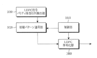
図10は、本発明の一実施形態による短縮されたLDPC符号を使用する送信装置の構成を示すブロック図である。 FIG. 10 is a block diagram illustrating a configuration of a transmission apparatus using a shortened LDPC code according to an embodiment of the present invention.
図10を参照すると、送信装置は、制御部1010、短縮パターン適用部1020、LDPC符号パリティ検査行列抽出部1040、及びLDPC符号化器1060を含む。LDPC符号パリティ検査行列抽出部1040は、短縮がなされたLDPC符号パリティ検査行列を抽出する。LDPC符号パリティ検査行列は、メモリから抽出することもでき、送信装置から与えられることもでき、或いは送信装置で生成することもできる。また、LDPC符号パリティ検査行列抽出部1040は、送信シンボルの送信変調方式を決定し、LDPC符号のパリティ検査行列で情報語に対応する列を複数の列グループにグルーピングし、この列グループの順序づけを行う。
Referring to FIG. 10, the transmission apparatus includes a
短縮パターン適用部1020は、短縮を介して得ようとする情報語の範囲を決定し、この情報語の範囲に基づいて、決定された変調方式を考慮して決定された短縮パターンに従って列グループに対し順次に列グループ単位の列グループの短縮を実行する。 The shortening pattern application unit 1020 determines a range of information words to be obtained through shortening, and based on the range of information words, the shortening pattern application unit 1020 assigns column groups to column groups according to the shortening pattern determined in consideration of the determined modulation scheme. On the other hand, the column group is shortened in units of column groups.
制御部1010は、送信変調方式及び情報語の長さに従って短縮パターンを決定するように短縮パターン適用部1020を制御し、短縮パターン適用部1020は、短縮されたビットに対応する位置に0の値を有するビットを挿入するか、又は与えられたLDPC符号のパリティ検査行列から短縮されたビットに対応する列を除去する。この短縮パターンは、メモリに格納されている短縮パターンを使用するか、シーケンス生成器(図示せず)を用いて短縮パターンを生成するか、又はパリティ検査行列及び与えられた情報語の長さに対して密度進化分析アルゴリズムなどを使用して得ることもできる。
The
LDPC符号化器1060は、制御部1010及び短縮パターン適用部1020により短縮されたLDPC符号に基づいて符号化を実行する。
The
図11は、短縮及びパンクチャーリングを同時に適用するDVB−S2 LDPC符号の送信装置の構成を示すブロック図である。特に、図11の送信装置は、図10の送信装置と比較してパンクチャーリングパターン適用部1180を含む。
FIG. 11 is a block diagram illustrating a configuration of a DVB-S2 LDPC code transmitting apparatus to which shortening and puncturing are applied simultaneously. In particular, the transmission apparatus in FIG. 11 includes a puncturing
図11を参照すると、短縮は、LDPC符号化器1060の入力段で実行され、パンクチャーリングは、LDPC符号化器1060の出力段で実行される。パンクチャーリングパターン適用部1180は、LDPC符号化器1060の出力にパンクチャーリングを適用する。パンクチャーリングを適用する方法については、図9のステップ915で説明した。
Referring to FIG. 11, the shortening is performed at the input stage of the
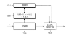
図12は、本発明の一実施形態による短縮を適用したLDPC符号を使用する受信装置の構成を示すブロック図である。特に、図12は、短縮されたDVB−S2 LDPC符号を使用する通信システムから送信された信号を受信し、受信した信号から短縮されたDVB−S2 LDPC符号の送信変調方式及び長さを検出する際、この受信した信号からユーザが所望するデータを復元する受信装置の例を示す。 FIG. 12 is a block diagram illustrating a configuration of a receiving apparatus using an LDPC code to which a shortening according to an embodiment of the present invention is applied. In particular, FIG. 12 receives a signal transmitted from a communication system using a shortened DVB-S2 LDPC code, and detects the transmission modulation scheme and length of the shortened DVB-S2 LDPC code from the received signal. In this case, an example of a receiving apparatus that restores data desired by the user from the received signal is shown.
図12を参照すると、受信装置は、制御部1210、短縮パターン判定/推定部1220、復調器1230、及びLDPC復号化器1240を含む。復調器1230は、短縮されたLDPC符号の受信及び復調を行い、この復調された信号を短縮パターン判定/推定部1220及びLDPC復号化器1240に提供する。短縮パターン判定/推定部1220は、制御部1210の制御の下で、復調された信号からLDPC符号の短縮パターンに関する情報の推定又は判定を行い、短縮されたビットの位置情報をLDPC復号化器1240に提供する。短縮パターン判定/推定部1220で短縮パターンの推定又は判定を行う方法は、メモリに格納されている短縮パターンを使用するか、シーケンス生成器(図示せず)を用いて短縮パターンを生成するか、或いはパリティ検査行列及び与えられた情報語の長さに対して密度進化分析アルゴリズムを使用することにより短縮パターンを得ることができる。
Referring to FIG. 12, the reception apparatus includes a
制御部1210は、短縮パターン判定/推定部1220が変調方式及び情報語の長さにより短縮パターンをLDPC復号化器1240に伝達するように制御する。短縮されたビットの値がゼロ(0)である確率が1(即ち、100%)であるため、LDPC復号化器1240は、短縮されたビットがゼロである確率の値1に基づいて、この短縮されたビットの復号化動作に入ることを許可するか否かを決定する。
The
LDPC復号化器1240は、短縮パターン判定/推定部1220により短縮されたDVB−S2 LDPC符号の長さに関する情報を受信すると、この受信した信号からユーザが希望するデータを復元する。
When the
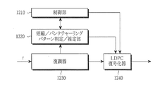
図13は、本発明の一実施形態による短縮及びパンクチャーリングの両方を適用したLDPC符号を使用する受信装置の構成を示すブロック図である。特に、図13に示す受信装置は、図12に示した受信装置の短縮パターン判定/推定部1220に代わる短縮/パンクチャーリングパターン判定/推定部1320を含む。
FIG. 13 is a block diagram illustrating a configuration of a receiving apparatus using an LDPC code to which both shortening and puncturing are applied according to an embodiment of the present invention. In particular, the receiving apparatus illustrated in FIG. 13 includes a shortening / puncturing pattern determination /
図13を参照すると、送信装置が短縮及びパンクチャーリングの両方を適用する場合、受信装置内の短縮/パンクチャーリングパターン判定/推定部1320は、短縮に対するパターン判定又は推定を先ず実行するか、パンクチャーリングに対するパターン判定又は推定を先ず実行するか、或いは、短縮に対するパターン判定又は推定及びパンクチャーリングに対するパターン判定又は推定を同時に実行してもよい。LDPC復号化器1240は、短縮及びパンクチャーリングの両方に関する情報を知っていないと復号化が不可能である。
Referring to FIG. 13, when the transmission apparatus applies both shortening and puncturing, the shortening / puncturing pattern determination /
図14は、本発明の一実施形態による受信装置の受信動作を示すフローチャートである。 FIG. 14 is a flowchart showing a receiving operation of the receiving apparatus according to the embodiment of the present invention.
図14を参照すると、復調器1230は、ステップ1401で短縮されたLDPC符号の受信及び復調を行う。短縮パターン判定/推定部1220は、ステップ1403で復調された信号から短縮/パンクチャーリングパターンの判定又は推定を行う。
Referring to FIG. 14, the
短縮パターン判定/推定部1220は、ステップ1405で、任意の短縮又はパンクチャーリングがなされたビットが存在するか否かを判定する。短縮又はパンクチャーリングがなされたビットが存在しない場合に、LDPC復号化器1240は、ステップ1411で復号化を実行する。しかし、短縮又はパンクチャーリングがなされたビットが存在する場合に、短縮パターン判定/推定部1220は、ステップ1407で、短縮/パンクチャーリングがなされたビットの位置情報をLDPC復号化器1240に送信する。
In
ステップ1409で、この短縮/パンクチャーリングがなされたビットの位置情報に基づいて、LDPC復号化器1240は、短縮されたビットの値が0である確率が1であると決定し、このパンクチャーリングがなされたビットが消失したビットであると決定する。その後に、LDPC復号化器1240は、ステップ1411でLDPC復号化を実行する。
In
以上、本発明を具体的な実施形態を参照して詳細に説明してきたが、本発明の範囲及び趣旨を逸脱することなく様々な変更が可能であるということは、当業者には明らかであり、本発明の範囲は、上述の実施形態に限定されるべきではなく、特許請求の範囲の記載及びこれと均等なものの範囲内で定められるべきである。 Although the present invention has been described in detail with reference to specific embodiments, it will be apparent to those skilled in the art that various modifications can be made without departing from the scope and spirit of the invention. The scope of the present invention should not be limited to the above-described embodiments, but should be defined within the scope of the appended claims and their equivalents.
610 送信器
611、1060 LDPC符号化器
613 変調器
620 無線チャネル
630 受信器
631、1230 復調器
633、1240 LDPC復号化器
1010、1210 制御部
1020 短縮パターン適用部
1040 LDPC符号パリティ検査行列抽出部
1180 パンクチャーリングパターン適用部
1220 短縮パターン判定/推定部
1320 短縮/パンクチャーリングパターン判定/推定部
610
Claims (12)
情報ビットを複数のビットグループに区分するステップと、
短縮される情報ビットの数を決定するステップと、
前記決定された短縮される情報ビットの数に基づいて短縮されるビットグループの数を決定するステップと、
予め定められたビットグループの順序に従って前記決定されたビットグループの情報ビットを短縮するステップと、
前記短縮された情報ビットを符号化するステップと、を有し、
情報ビットの長さが7200であり、符号語の長さが16200である場合に、
前記予め定められたビットグループの順序は、18、17、16、15、14、13、12、11、4、10、9、8、7、3、2、1、6、5、19、及び0であることを特徴とするチャネル符号化方法。 A channel coding method in a system using a low density parity check (LDPC) code, comprising:
Partitioning information bits into a plurality of bit groups;
Determining the number of information bits to be shortened;
Determining a number of bit groups to be shortened based on the determined number of shortened information bits;
Shortening the information bits of the determined bit group according to a predetermined order of bit groups;
Encoding the shortened information bits;
If the information bit length is 7200 and the codeword length is 16200,
The predetermined bit group order is 18, 17, 16, 15, 14, 13, 12, 11, 4, 10, 9, 8, 7, 3, 2, 1, 6, 5, 19, and A channel coding method characterized by being zero.
前記予め定められたビットグループの順序に従って0番目のビットグループから(m−1)番目のビットグループまでのビットグループの情報ビットを短縮するステップと、
前記予め定められたビットグループの順序に従ってm番目のビットグループ内の(7200−K2−360m)情報ビットを短縮するステップと、を有し、
K2は、短縮により取得される情報ビットの数であり、(7200−K2)は、短縮される情報ビットの数であり、
Shortening information bits of bit groups from the 0th bit group to the (m−1) th bit group according to the predetermined order of the bit groups;
Shortening (7200-K 2 -360m) information bits in the m th bit group according to the predetermined bit group order;
K 2 is the number of information bits acquired by shortening, (7200−K 2 ) is the number of information bits shortened,
情報ビットを複数のビットグループに区分し、短縮される情報ビットの数を決定し、前記決定された短縮される情報ビットの数に基づいて短縮されるビットグループの数を決定し、予め定められたビットグループの順序に従って前記決定されたビットグループの情報ビットを短縮する短縮パターン適用部と、
前記短縮された情報ビットを符号化する符号化器と、を備え、
情報ビットの長さが7200であり、符号語の長さが16200である場合に、
前記予め定められたビットグループの順序は、18、17、16、15、14、13、12、11、4、10、9、8、7、3、2、1、6、5、19、及び0であることを特徴とするチャネル符号化装置。 A channel encoder in a system using a low density parity check (LDPC) code, comprising:
The information bits are divided into a plurality of bit groups, the number of information bits to be shortened is determined, and the number of bit groups to be shortened is determined based on the determined number of information bits to be shortened. A shortening pattern application unit that shortens the information bits of the determined bit group according to the order of the bit groups.
An encoder for encoding the shortened information bits,
If the information bit length is 7200 and the codeword length is 16200,
The predetermined bit group order is 18, 17, 16, 15, 14, 13, 12, 11, 4, 10, 9, 8, 7, 3, 2, 1, 6, 5, 19, and A channel encoding apparatus characterized by being zero.
前記短縮パターン適用部は、前記予め定められたビットグループの順序に従って0番目のビットグループから(m−1)番目のビットグループまでのビットグループの情報ビットを短縮し、前記予め定められたビットグループの順序に従ってm番目のビットグループ内の(7200−K2−360m)情報ビットを短縮し、
K2は、短縮により取得される情報ビットの数であり、(7200−K2)は、短縮される情報ビットの数であり、
The shortening pattern application unit shortens information bits of bit groups from the 0th bit group to the (m−1) th bit group according to the predetermined order of the bit groups, and the predetermined bit group the m-th (7200-K 2 -360m) information bits in the bit group shortening according to the order of,
K 2 is the number of information bits acquired by shortening, (7200−K 2 ) is the number of information bits shortened,
受信された信号を復調するステップと、
短縮された情報ビットの位置を決定するステップと、
前記決定された短縮された情報ビットの位置を考慮して前記復調された信号を復号化するステップと、を有し、
前記短縮された情報ビットの位置を決定するステップは、
短縮された情報ビットの数を決定するステップと、
前記決定された短縮された情報ビットの数に基づいて短縮されたビットグループの数を決定するステップと、
予め定められたビットグループの順序を取得するステップと、を有し、
情報ビットの長さが7200であり、符号語の長さが16200である場合に、
前記予め定められたビットグループの順序は、18、17、16、15、14、13、12、11、4、10、9、8、7、3、2、1、6、5、19、及び0であることを特徴とするチャネル復号化方法。 A channel decoding method in a system using a low density parity check (LDPC) code comprising:
Demodulating the received signal; and
Determining the location of the shortened information bits;
Decoding the demodulated signal taking into account the determined shortened information bit position; and
Determining the position of the shortened information bit comprises:
Determining the number of shortened information bits;
Determining a number of shortened bit groups based on the determined number of shortened information bits;
Obtaining a predetermined bit group order; and
If the information bit length is 7200 and the codeword length is 16200,
The predetermined bit group order is 18, 17, 16, 15, 14, 13, 12, 11, 4, 10, 9, 8, 7, 3, 2, 1, 6, 5, 19, and A channel decoding method characterized by being zero.
前記予め定められたビットグループの順序に従って0番目のビットグループから(m−1)番目のビットグループまでのビットグループの情報ビットが短縮されたことに決定するステップと、
前記予め定められたビットグループの順序に従ってm番目のビットグループ内の(7200−K2−360m)情報ビットが短縮されたことに決定するステップと、を有し、
K2は、短縮により取得される情報ビットの数であり、(7200−K2)は、短縮された情報ビットの数であり、
Determining that the information bits of the bit groups from the 0th bit group to the (m−1) th bit group are shortened according to the predetermined order of the bit groups;
Determining that (7200-K 2 -360m) information bits in the m th bit group have been shortened according to the predetermined bit group order;
K 2 is the number of information bits acquired by shortening, (7200−K 2 ) is the number of shortened information bits,
受信された信号を復調する復調器と、
短縮された情報ビットの位置を決定する短縮パターン決定部と、
前記決定された短縮された情報ビットの位置を考慮して前記復調された信号を復号化する復号化器と、を備え、
前記短縮された情報ビットの位置は、
短縮された情報ビットの数を決定し、前記決定された短縮された情報ビットの数に基づいて短縮されたビットグループの数を決定し、予め定められたビットグループの順序を取得することにより決定され、
情報ビットの長さが7200であり、符号語の長さが16200である場合に、
前記予め定められたビットグループの順序は、18、17、16、15、14、13、12、11、4、10、9、8、7、3、2、1、6、5、19、及び0であることを特徴とするチャネル復号化装置。 A channel decoding apparatus in a system using a low density parity check (LDPC) code, comprising:
A demodulator that demodulates the received signal;
A shortened pattern determination unit that determines the position of the shortened information bits;
A decoder that decodes the demodulated signal taking into account the determined shortened information bit position;
The position of the shortened information bit is
Determined by determining the number of shortened information bits, determining the number of shortened bit groups based on the determined number of shortened information bits, and obtaining a predetermined order of the bit groups And
If the information bit length is 7200 and the codeword length is 16200,
The predetermined bit group order is 18, 17, 16, 15, 14, 13, 12, 11, 4, 10, 9, 8, 7, 3, 2, 1, 6, 5, 19, and A channel decoding apparatus characterized by being zero.
前記短縮パターン適用部は、前記予め定められたビットグループの順序に従って0番目のビットグループから(m−1)番目のビットグループまでのビットグループの情報ビットが短縮されたことに決定し、前記予め定められたビットグループの順序に従ってm番目のビットグループ内の(7200−K2−360m)情報ビットが短縮されたことに決定し、
K2は、短縮により取得される情報ビットの数であり、(7200−K2)は、短縮される情報ビットの数であり、
The shortening pattern application unit determines that the information bits of the bit groups from the 0th bit group to the (m−1) th bit group are shortened according to the predetermined order of the bit groups, Determining that the (7200-K 2 -360m) information bits in the mth bit group have been shortened according to a defined bit group order;
K 2 is the number of information bits acquired by shortening, (7200−K 2 ) is the number of information bits shortened,
Applications Claiming Priority (6)
| Application Number | Priority Date | Filing Date | Title |
|---|---|---|---|
| KR20080017279 | 2008-02-26 | ||
| KR10-2008-0017279 | 2008-02-26 | ||
| KR20080022484 | 2008-03-11 | ||
| KR10-2008-0022484 | 2008-03-11 | ||
| KR1020080025144A KR101503059B1 (en) | 2008-02-26 | 2008-03-18 | Apparatus and method for channel encoding and decoding in communication system using low-density parity-check codes |
| KR10-2008-0025144 | 2008-03-18 |
Related Parent Applications (1)
| Application Number | Title | Priority Date | Filing Date |
|---|---|---|---|
| JP2010547571A Division JP5440804B2 (en) | 2008-02-26 | 2009-02-26 | Channel coding method and apparatus in system using low density parity check code |
Publications (2)
| Publication Number | Publication Date |
|---|---|
| JP2014014193A true JP2014014193A (en) | 2014-01-23 |
| JP5648224B2 JP5648224B2 (en) | 2015-01-07 |
Family
ID=40677811
Family Applications (3)
| Application Number | Title | Priority Date | Filing Date |
|---|---|---|---|
| JP2010547571A Active JP5440804B2 (en) | 2008-02-26 | 2009-02-26 | Channel coding method and apparatus in system using low density parity check code |
| JP2013220346A Active JP5648223B2 (en) | 2008-02-26 | 2013-10-23 | Channel decoding method and apparatus in system using low density parity check code |
| JP2013220347A Active JP5648224B2 (en) | 2008-02-26 | 2013-10-23 | Method and apparatus for channel coding and decoding in a system using low density parity check code |
Family Applications Before (2)
| Application Number | Title | Priority Date | Filing Date |
|---|---|---|---|
| JP2010547571A Active JP5440804B2 (en) | 2008-02-26 | 2009-02-26 | Channel coding method and apparatus in system using low density parity check code |
| JP2013220346A Active JP5648223B2 (en) | 2008-02-26 | 2013-10-23 | Channel decoding method and apparatus in system using low density parity check code |
Country Status (20)
| Country | Link |
|---|---|
| US (1) | US8176384B2 (en) |
| EP (5) | EP2490337B1 (en) |
| JP (3) | JP5440804B2 (en) |
| KR (1) | KR101503059B1 (en) |
| CN (3) | CN103281089B (en) |
| AU (1) | AU2009217934B2 (en) |
| CY (2) | CY1124200T1 (en) |
| DK (3) | DK2363962T3 (en) |
| ES (5) | ES2611145T3 (en) |
| HR (3) | HRP20221436T1 (en) |
| HU (4) | HUE055052T2 (en) |
| LT (3) | LT2490337T (en) |
| MY (2) | MY173292A (en) |
| PL (3) | PL3849088T3 (en) |
| PT (3) | PT3849088T (en) |
| RU (4) | RU2012107861A (en) |
| SG (2) | SG188821A1 (en) |
| SI (3) | SI3849088T1 (en) |
| TW (3) | TWI506963B (en) |
| WO (1) | WO2009107990A2 (en) |
Families Citing this family (31)
| Publication number | Priority date | Publication date | Assignee | Title |
|---|---|---|---|---|
| CN101889398B (en) * | 2007-12-06 | 2013-10-23 | 三星电子株式会社 | Method and apparatus for encoding and decoding channel in communication system using low-density parity-check codes |
| KR101503059B1 (en) * | 2008-02-26 | 2015-03-19 | 삼성전자주식회사 | Apparatus and method for channel encoding and decoding in communication system using low-density parity-check codes |
| KR101670511B1 (en) | 2010-05-07 | 2016-10-28 | 삼성전자주식회사 | Apparatus and method for channel encoding and decoding in communication system using low-density parity-check codes |
| CA2818126C (en) * | 2010-12-03 | 2018-06-19 | Samsung Electronics Co., Ltd. | Apparatus and method for transmitting and receiving data in communication system |
| JP5630283B2 (en) | 2011-01-19 | 2014-11-26 | ソニー株式会社 | Data processing apparatus and data processing method |
| JP2012151655A (en) * | 2011-01-19 | 2012-08-09 | Sony Corp | Data processing device and data processing method |
| JP5630282B2 (en) * | 2011-01-19 | 2014-11-26 | ソニー株式会社 | Data processing apparatus and data processing method |
| JP2012151656A (en) * | 2011-01-19 | 2012-08-09 | Sony Corp | Data processing device and data processing method |
| JP5672489B2 (en) | 2011-02-08 | 2015-02-18 | ソニー株式会社 | Data processing apparatus and data processing method |
| JP5637393B2 (en) * | 2011-04-28 | 2014-12-10 | ソニー株式会社 | Data processing apparatus and data processing method |
| JP5648852B2 (en) * | 2011-05-27 | 2015-01-07 | ソニー株式会社 | Data processing apparatus and data processing method |
| JP5664919B2 (en) | 2011-06-15 | 2015-02-04 | ソニー株式会社 | Data processing apparatus and data processing method |
| EP2536030A1 (en) * | 2011-06-16 | 2012-12-19 | Panasonic Corporation | Bit permutation patterns for BICM with LDPC codes and QAM constellations |
| KR101791477B1 (en) * | 2011-10-10 | 2017-10-30 | 삼성전자주식회사 | Apparatus and method for transmitting and receiving data in communication/broadcasting system |
| EP3442128B1 (en) * | 2013-02-08 | 2023-08-02 | Saturn Licensing LLC | Ldpc codes of length 64800 suitable for dvb-s2x transmission systems |
| US9124403B2 (en) | 2013-04-30 | 2015-09-01 | Qualcomm Incorporated | Puncturing scheme based decoder optimizations |
| KR101776275B1 (en) * | 2014-02-19 | 2017-09-07 | 삼성전자주식회사 | Transmitting apparatus and interleaving method thereof |
| US10784901B2 (en) * | 2015-11-12 | 2020-09-22 | Qualcomm Incorporated | Puncturing for structured low density parity check (LDPC) codes |
| CN105846827B (en) * | 2016-03-17 | 2019-02-01 | 哈尔滨工程大学 | Iterative joint message source and channel interpretation method based on arithmetic code and low density parity check code |
| US11043966B2 (en) | 2016-05-11 | 2021-06-22 | Qualcomm Incorporated | Methods and apparatus for efficiently generating multiple lifted low-density parity-check (LDPC) codes |
| US10454499B2 (en) | 2016-05-12 | 2019-10-22 | Qualcomm Incorporated | Enhanced puncturing and low-density parity-check (LDPC) code structure |
| US10313057B2 (en) | 2016-06-01 | 2019-06-04 | Qualcomm Incorporated | Error detection in wireless communications using sectional redundancy check information |
| US9917675B2 (en) | 2016-06-01 | 2018-03-13 | Qualcomm Incorporated | Enhanced polar code constructions by strategic placement of CRC bits |
| US10291354B2 (en) | 2016-06-14 | 2019-05-14 | Qualcomm Incorporated | High performance, flexible, and compact low-density parity-check (LDPC) code |
| CN107645358B (en) * | 2016-07-22 | 2020-07-28 | 北京大学 | Code rate self-adaptive data coordination method used in continuous variable quantum key distribution |
| BR112019001032A2 (en) | 2016-07-27 | 2019-04-30 | Qualcomm Incorporated | hybrid auto repeat request feedback (harq) bit design for polar codes |
| WO2018084735A1 (en) * | 2016-11-03 | 2018-05-11 | Huawei Technologies Co., Ltd. | Efficiently decodable qc-ldpc code |
| US10312939B2 (en) | 2017-06-10 | 2019-06-04 | Qualcomm Incorporated | Communication techniques involving pairwise orthogonality of adjacent rows in LPDC code |
| RU2651222C1 (en) * | 2017-07-05 | 2018-04-18 | Федеральное государственное бюджетное образовательное учреждение высшего образования "Рязанский государственный радиотехнический университет" | Method for decoding ldpc codes and device for its implementation |
| BR112020000140A2 (en) | 2017-07-07 | 2020-08-04 | Qualcomm Incorporated | communication techniques applying low density parity check code base chart selection |
| KR20220022801A (en) | 2020-08-19 | 2022-02-28 | 삼성전자주식회사 | Method and apparatus for decoding a signal in a wireless communication system |
Citations (4)
| Publication number | Priority date | Publication date | Assignee | Title |
|---|---|---|---|---|
| JP2007525931A (en) * | 2004-05-14 | 2007-09-06 | モトローラ・インコーポレイテッド | Code structure of irregular shortened LDPC code with good function |
| JP2007531385A (en) * | 2004-05-12 | 2007-11-01 | サムスン エレクトロニクス カンパニー リミテッド | Apparatus and method for encoding / decoding block low density parity check code having variable coding rate |
| JP5302972B2 (en) * | 2007-12-06 | 2013-10-02 | サムスン エレクトロニクス カンパニー リミテッド | CHANNEL ENCODING METHOD AND DECODING METHOD IN THE SYSTEM USING LOW DENSITY PARITY CHECK CODE AND DEVICE THEREOF |
| JP5440804B2 (en) * | 2008-02-26 | 2014-03-12 | サムスン エレクトロニクス カンパニー リミテッド | Channel coding method and apparatus in system using low density parity check code |
Family Cites Families (26)
| Publication number | Priority date | Publication date | Assignee | Title |
|---|---|---|---|---|
| ATE414349T1 (en) * | 1999-12-20 | 2008-11-15 | Research In Motion Ltd | HYBRID REPOST PROMPT SYSTEM AND METHOD |
| US6633856B2 (en) * | 2001-06-15 | 2003-10-14 | Flarion Technologies, Inc. | Methods and apparatus for decoding LDPC codes |
| US7222284B2 (en) * | 2003-06-26 | 2007-05-22 | Nokia Corporation | Low-density parity-check codes for multiple code rates |
| KR100922956B1 (en) * | 2003-10-14 | 2009-10-22 | 삼성전자주식회사 | Method for encoding of low density parity check code |
| US7383487B2 (en) * | 2004-01-10 | 2008-06-03 | Broadcom Corporation | IPHD (iterative parallel hybrid decoding) of various MLC (multi-level code) signals |
| WO2006027818A1 (en) * | 2004-09-03 | 2006-03-16 | Mitsubishi Denki Kabushiki Kaisha | Ldpc code generating method and communication apparatus |
| US7996746B2 (en) * | 2004-10-12 | 2011-08-09 | Nortel Networks Limited | Structured low-density parity-check (LDPC) code |
| US7581159B2 (en) * | 2004-11-23 | 2009-08-25 | Texas Instruments Incorporated | Simplified decoding using structured and punctured LDPC codes |
| WO2006075382A1 (en) | 2005-01-14 | 2006-07-20 | Fujitsu Limited | Encoding method, decoding method, and device thereof |
| US7953047B2 (en) * | 2005-01-24 | 2011-05-31 | Qualcomm Incorporated | Parser for multiple data streams in a communication system |
| US8036205B2 (en) | 2005-06-13 | 2011-10-11 | Qualcomm Incorporated | Methods and apparatus for supporting uplinks with remote base stations |
| KR100946884B1 (en) * | 2005-07-15 | 2010-03-09 | 삼성전자주식회사 | Channel interleaving/de-interleaving apparatus in a communication system using a low density parity check code and control method thereof |
| CN100584011C (en) * | 2005-09-02 | 2010-01-20 | 清华大学 | Correction coding method for ground digital television broadcast |
| KR100856235B1 (en) * | 2005-09-26 | 2008-09-03 | 삼성전자주식회사 | Apparatus and method for encoding and decoding block low density parity check codes with a variable coding rate |
| CN100502245C (en) * | 2005-10-21 | 2009-06-17 | 中兴通讯股份有限公司 | A coding device and method for low density parity check code of supporting any code rate/code length |
| KR101351140B1 (en) | 2005-11-22 | 2014-01-15 | 조지아 테크 리서치 코오포레이션 | Apparatus and method for transmitting/receiving signal in a communication system |
| EP1959598A4 (en) * | 2005-12-09 | 2010-01-27 | Mitsubishi Electric Corp | Communication method and communication apparatus |
| US7584406B2 (en) * | 2005-12-20 | 2009-09-01 | Samsung Electronics Co., Ltd. | LDPC concatenation rules for IEEE 802.11n system with packets length specific in octets |
| US7631246B2 (en) * | 2006-01-09 | 2009-12-08 | Broadcom Corporation | LDPC (low density parity check) code size adjustment by shortening and puncturing |
| US8020062B2 (en) * | 2006-06-15 | 2011-09-13 | Samsung Electronics Co., Ltd. | Apparatus and method of encoding/decoding block low density parity check codes in a communication system |
| DE102006039191A1 (en) | 2006-08-21 | 2008-03-20 | Wacker Chemie Ag | Continuous production of organosilanes |
| KR100983147B1 (en) | 2006-09-06 | 2010-09-20 | 가부시끼 가이샤 구보다 | Combine-harvester |
| KR101502624B1 (en) * | 2007-12-06 | 2015-03-17 | 삼성전자주식회사 | Apparatus and method for channel encoding and decoding in communication system using low-density parity-check codes |
| US8209590B2 (en) * | 2008-11-05 | 2012-06-26 | Broadcom Corporation | Header encoding/decoding |
| EP2337259B1 (en) * | 2009-11-18 | 2021-08-25 | Samsung Electronics Co., Ltd. | Method and apparatus for transmitting and receiving data in a communication system |
| KR101670511B1 (en) * | 2010-05-07 | 2016-10-28 | 삼성전자주식회사 | Apparatus and method for channel encoding and decoding in communication system using low-density parity-check codes |
-
2008
- 2008-03-18 KR KR1020080025144A patent/KR101503059B1/en active IP Right Grant
-
2009
- 2009-02-26 TW TW102115481A patent/TWI506963B/en active
- 2009-02-26 LT LTEP12166288.6T patent/LT2490337T/en unknown
- 2009-02-26 ES ES09153740.7T patent/ES2611145T3/en active Active
- 2009-02-26 PL PL21158617.7T patent/PL3849088T3/en unknown
- 2009-02-26 DK DK11151068.1T patent/DK2363962T3/en active
- 2009-02-26 EP EP12166288.6A patent/EP2490337B1/en active Active
- 2009-02-26 MY MYPI2014003229A patent/MY173292A/en unknown
- 2009-02-26 DK DK21158617.7T patent/DK3849088T3/en active
- 2009-02-26 US US12/393,670 patent/US8176384B2/en active Active
- 2009-02-26 HU HUE12166288A patent/HUE055052T2/en unknown
- 2009-02-26 ES ES09154641.6T patent/ES2610133T3/en active Active
- 2009-02-26 MY MYPI20103727 patent/MY152769A/en unknown
- 2009-02-26 RU RU2012107861/08A patent/RU2012107861A/en not_active Application Discontinuation
- 2009-02-26 ES ES11151068T patent/ES2873091T3/en active Active
- 2009-02-26 SG SG2013014550A patent/SG188821A1/en unknown
- 2009-02-26 PT PT211586177T patent/PT3849088T/en unknown
- 2009-02-26 HU HUE09153740A patent/HUE031516T2/en unknown
- 2009-02-26 EP EP21158617.7A patent/EP3849088B1/en active Active
- 2009-02-26 PL PL11151068T patent/PL2363962T3/en unknown
- 2009-02-26 ES ES21158617T patent/ES2927436T3/en active Active
- 2009-02-26 EP EP09154641.6A patent/EP2099136B1/en active Active
- 2009-02-26 TW TW098106144A patent/TWI399043B/en active
- 2009-02-26 HR HRP20221436TT patent/HRP20221436T1/en unknown
- 2009-02-26 SG SG10201401192SA patent/SG10201401192SA/en unknown
- 2009-02-26 PL PL12166288T patent/PL2490337T3/en unknown
- 2009-02-26 HU HUE21158617A patent/HUE060734T2/en unknown
- 2009-02-26 EP EP11151068.1A patent/EP2363962B1/en active Active
- 2009-02-26 AU AU2009217934A patent/AU2009217934B2/en active Active
- 2009-02-26 CN CN201310149574.0A patent/CN103281089B/en active Active
- 2009-02-26 SI SI200932172T patent/SI3849088T1/en unknown
- 2009-02-26 ES ES12166288T patent/ES2875479T3/en active Active
- 2009-02-26 LT LTEP11151068.1T patent/LT2363962T/en unknown
- 2009-02-26 CN CN2009801145927A patent/CN102017426B/en active Active
- 2009-02-26 PT PT111510681T patent/PT2363962T/en unknown
- 2009-02-26 RU RU2010135575/08A patent/RU2454794C2/en active
- 2009-02-26 CN CN201310149429.2A patent/CN103281088B/en active Active
- 2009-02-26 TW TW102115482A patent/TWI506964B/en active
- 2009-02-26 SI SI200932126T patent/SI2490337T1/en unknown
- 2009-02-26 PT PT121662886T patent/PT2490337T/en unknown
- 2009-02-26 WO PCT/KR2009/000929 patent/WO2009107990A2/en active Application Filing
- 2009-02-26 DK DK12166288.6T patent/DK2490337T3/en active
- 2009-02-26 LT LTEP21158617.7T patent/LT3849088T/en unknown
- 2009-02-26 HU HUE11151068A patent/HUE055053T2/en unknown
- 2009-02-26 SI SI200932125T patent/SI2363962T1/en unknown
- 2009-02-26 EP EP09153740.7A patent/EP2096760B1/en active Active
- 2009-02-26 JP JP2010547571A patent/JP5440804B2/en active Active
-
2012
- 2012-03-01 RU RU2012107862/08A patent/RU2490791C1/en active
-
2013
- 2013-04-09 RU RU2013115889/08A patent/RU2543553C2/en active
- 2013-10-23 JP JP2013220346A patent/JP5648223B2/en active Active
- 2013-10-23 JP JP2013220347A patent/JP5648224B2/en active Active
-
2021
- 2021-06-04 CY CY20211100489T patent/CY1124200T1/en unknown
- 2021-06-07 CY CY20211100494T patent/CY1124205T1/en unknown
- 2021-06-10 HR HRP20210936TT patent/HRP20210936T1/en unknown
- 2021-06-10 HR HRP20210937TT patent/HRP20210937T1/en unknown
Patent Citations (4)
| Publication number | Priority date | Publication date | Assignee | Title |
|---|---|---|---|---|
| JP2007531385A (en) * | 2004-05-12 | 2007-11-01 | サムスン エレクトロニクス カンパニー リミテッド | Apparatus and method for encoding / decoding block low density parity check code having variable coding rate |
| JP2007525931A (en) * | 2004-05-14 | 2007-09-06 | モトローラ・インコーポレイテッド | Code structure of irregular shortened LDPC code with good function |
| JP5302972B2 (en) * | 2007-12-06 | 2013-10-02 | サムスン エレクトロニクス カンパニー リミテッド | CHANNEL ENCODING METHOD AND DECODING METHOD IN THE SYSTEM USING LOW DENSITY PARITY CHECK CODE AND DEVICE THEREOF |
| JP5440804B2 (en) * | 2008-02-26 | 2014-03-12 | サムスン エレクトロニクス カンパニー リミテッド | Channel coding method and apparatus in system using low density parity check code |
Non-Patent Citations (4)
| Title |
|---|
| JPN6014033834; Tomoaki Ohtsuki: 'LDPC Codes in Communications and Broadcasting' IEICE Transactions on Communications Vol.E90-B, No.3, 20070301, pp.440-453 * |
| JPN6014033835; Marco Gomes et al.: 'High throughput encoder architecture for DVB-S2 LDPC-IRA codes' Microelectronics, 2007. ICM 2007. Internatonal Conference on , 20071231 * |
| JPN6014033837; Tao Tian et al.: 'Construction of Rate-Compatible LDPC Codes UtilizingInformation Shortening and Parity Puncturing' EURASIP Journal onWireless Communications and Networking , 2005 * |
| JPN6014033838; Massoud Khajeh et al.: 'A New High Performance LDPC Code for DVB-S2' A Thesis in the department of Electrical and Computer Engineering at Concordia University , 2006, pp.43-52 * |
Also Published As
Similar Documents
| Publication | Publication Date | Title |
|---|---|---|
| JP5648224B2 (en) | Method and apparatus for channel coding and decoding in a system using low density parity check code | |
| JP5644010B2 (en) | Method and apparatus for channel decoding in a system using low density parity check code | |
| JP5583833B2 (en) | Channel decoding method and apparatus in communication system using low density parity check code | |
| KR101503656B1 (en) | Apparatus and method for channel encoding and decoding in communication system using low-density parity-check codes | |
| JP5441282B2 (en) | CHANNEL ENCODING METHOD AND DECODING METHOD IN THE SYSTEM USING LOW DENSITY PARITY CHECK CODE AND DEVICE THEREOF | |
| KR101503655B1 (en) | Apparatus and method for channel encoding and decoding in communication system using low-density parity-check codes |
Legal Events
| Date | Code | Title | Description |
|---|---|---|---|
| A621 | Written request for application examination |
Free format text: JAPANESE INTERMEDIATE CODE: A621 Effective date: 20131023 |
|
| TRDD | Decision of grant or rejection written | ||
| A01 | Written decision to grant a patent or to grant a registration (utility model) |
Free format text: JAPANESE INTERMEDIATE CODE: A01 Effective date: 20140812 |
|
| A61 | First payment of annual fees (during grant procedure) |
Free format text: JAPANESE INTERMEDIATE CODE: A61 Effective date: 20140903 |
|
| A61 | First payment of annual fees (during grant procedure) |
Free format text: JAPANESE INTERMEDIATE CODE: A61 Effective date: 20141021 |
|
| R150 | Certificate of patent or registration of utility model |
Ref document number: 5648224 Country of ref document: JP Free format text: JAPANESE INTERMEDIATE CODE: R150 |
|
| R250 | Receipt of annual fees |
Free format text: JAPANESE INTERMEDIATE CODE: R250 |
|
| R250 | Receipt of annual fees |
Free format text: JAPANESE INTERMEDIATE CODE: R250 |
|
| R250 | Receipt of annual fees |
Free format text: JAPANESE INTERMEDIATE CODE: R250 |
|
| R250 | Receipt of annual fees |
Free format text: JAPANESE INTERMEDIATE CODE: R250 |
|
| R250 | Receipt of annual fees |
Free format text: JAPANESE INTERMEDIATE CODE: R250 |
|
| R250 | Receipt of annual fees |
Free format text: JAPANESE INTERMEDIATE CODE: R250 |
|
| R250 | Receipt of annual fees |
Free format text: JAPANESE INTERMEDIATE CODE: R250 |