JP2014013346A - Rotating/swinging device - Google Patents

Rotating/swinging device Download PDF

Info

Publication number
JP2014013346A
JP2014013346A JP2012151344A JP2012151344A JP2014013346A JP 2014013346 A JP2014013346 A JP 2014013346A JP 2012151344 A JP2012151344 A JP 2012151344A JP 2012151344 A JP2012151344 A JP 2012151344A JP 2014013346 A JP2014013346 A JP 2014013346A
Authority
JP
Japan
Prior art keywords
gear
rotation
swing
unit
driven gear
Prior art date
Legal status (The legal status is an assumption and is not a legal conclusion. Google has not performed a legal analysis and makes no representation as to the accuracy of the status listed.)
Pending
Application number
JP2012151344A
Other languages
Japanese (ja)
Inventor
Katsuhisa Sato
勝久 佐藤
Current Assignee (The listed assignees may be inaccurate. Google has not performed a legal analysis and makes no representation or warranty as to the accuracy of the list.)
Faurecia Clarion Electronics Co Ltd
Original Assignee
Clarion Co Ltd
Priority date (The priority date is an assumption and is not a legal conclusion. Google has not performed a legal analysis and makes no representation as to the accuracy of the date listed.)
Filing date
Publication date
Application filed by Clarion Co Ltd filed Critical Clarion Co Ltd
Priority to JP2012151344A priority Critical patent/JP2014013346A/en
Publication of JP2014013346A publication Critical patent/JP2014013346A/en
Pending legal-status Critical Current

Links

Images

Abstract

PROBLEM TO BE SOLVED: To provide a rotating/swinging device that has a configuration advantageous to reduce its size.SOLUTION: A rotating/swinging device comprises: a driven gear 25 normally/reversely rotated by the normal/reverse rotation of a single motor 21; and a swing unit 27 swung in the direction of rotation of the driven gear 25 by frictional contact with the driven gear 25, and holding a first gear 28 and a second gear 29, which are engaged with the driven gear 25. A camera unit 11 is rotated by engaging the first gear 28 with a rotation input gear 12A through swinging the swing unit 27 to one direction. Also, the camera unit 11 is swung by engaging the second gear 29 with a swing input gear 52A through swinging the swing unit 27 to the other side.

Description

本発明は、カメラユニットなどのユニットを回動および揺動させる回動・揺動装置に関する。   The present invention relates to a rotation / oscillation device that rotates and swings a unit such as a camera unit.

従来、カメラの視点を略全方位で動かすためにカメラユニットを回動(例えば、水平回動)および揺動(例えば、上下回動)させる装置があり、回動と揺動の各々に駆動力を必要とするため、駆動源となるモータを2つ備えていた(例えば、特許文献1参照)。
また、従来、1つのモータの同方向の回転を用いて切替アームを揺動させることで、フィルムの巻き上げ機構のギアから巻き戻し機構のギアに噛合し、フィルムの巻き上げ・巻き戻しを行うカメラのトルク検知装置も提案されている(例えば、特許文献2参照)。
Conventionally, there has been a device for rotating (for example, horizontal rotation) and swinging (for example, vertical rotation) to move the camera viewpoint in almost all directions, and each of the rotation and swing has a driving force. Therefore, two motors serving as driving sources were provided (see, for example, Patent Document 1).
Further, conventionally, the switching arm is swung using the rotation of one motor in the same direction, so that the gear of the film winding mechanism is engaged with the gear of the rewinding mechanism, and the camera that winds and rewinds the film is used. A torque detection device has also been proposed (see, for example, Patent Document 2).

特開2004−212465号公報JP 2004-212465 A 特開平1−245233号公報JP-A-1-245233

しかしながら、従来の回動・揺動装置は、モータを2つ必要とするため、駆動部品が大きくなってしまい、小型化および低コスト化に不利であった。
また、1つのモータでフィルムの巻き上げ・巻き戻しを行う装置については、構成が複雑化し、部品点数も多くなってしまう。また、この装置の構成を適用してカメラなどのユニットを独立して回転および揺動させることはできない。
However, since the conventional rotating / swinging device requires two motors, the driving parts are large, which is disadvantageous for downsizing and cost reduction.
In addition, an apparatus that winds and rewinds a film with a single motor is complicated in configuration and increases the number of parts. Further, it is not possible to independently rotate and swing a unit such as a camera by applying this apparatus configuration.

本発明は、上述した事情に鑑みてなされたものであり、小型化に有利な構成を備えた回動・揺動装置を提供することを目的とする。   The present invention has been made in view of the above-described circumstances, and an object of the present invention is to provide a rotation / oscillation device having a configuration advantageous for downsizing.

上記目的を達成するために、本発明は、所定のユニットを回動させる回動機構と前記ユニットを揺動させる揺動機構とを備える回動・揺動装置において、単一のモータの正転/逆転によって正転/逆転する被動ギアと、前記被動ギアとの摩擦接触により前記被動ギアの回転方向に応じて一方側/他方側へ揺動するとともに、前記被動ギアに噛み合う第一ギアおよび第二ギアを保持する揺動部材とを備え、前記回動機構は、前記揺動部材が一方側または他方側へ揺動した場合に、前記第一ギアが噛合する回動入力ギアを有し、この入力ギアの回転で前記ユニットを回動させ、前記揺動機構は、前記揺動部材が他方側または一方側へ揺動した場合に、前記第二ギアが噛合する揺動入力ギアを有し、この入力ギアの回転で前記ユニットを揺動させる回転−揺動変換機構であることを特徴とする。
この構成によれば、単一のモータの正転/逆転によってユニットの回動と揺動とを切り替えることができ、2モータのものと比べて部品点数を低減し、小型化に有利な構成にすることができる。
In order to achieve the above object, the present invention provides a rotation / oscillation device comprising a rotation mechanism for rotating a predetermined unit and a swing mechanism for swinging the unit. The first gear and the second gear which are swung to one side / the other side according to the rotation direction of the driven gear and are engaged with the driven gear by frictional contact with the driven gear which rotates forward / reversely by the reverse rotation and the driven gear. A pivoting member that holds two gears, and the pivoting mechanism includes a pivoting input gear that meshes with the first gear when the pivoting member pivots to one side or the other side. The unit is rotated by the rotation of the input gear, and the swing mechanism has a swing input gear that meshes with the second gear when the swing member swings to the other side or one side. The unit is swung by the rotation of the input gear. Rolling - characterized in that it is a rocking conversion mechanism.
According to this configuration, the rotation and swing of the unit can be switched by forward / reverse rotation of a single motor, and the number of parts is reduced compared to the one of two motors, which is advantageous for downsizing. can do.

上記構成において、前記揺動部材は、前記被動ギアに揺動自在に挿入されるようにしても良い。この場合、前記揺動部材は、前記被動ギアの軸心を貫通する貫通孔に挿入される挿入軸を有し、この挿入軸が前記被動ギアに摩擦接触して前記被動ギアの回転方向に応じて前記揺動部材を揺動させるようにしても良い。
また、上記構成において、前記第一ギアと前記第二ギアとは、前記被動ギアの周方向に間隔を空けて配置され、前記第一ギアと前記第二ギアとの間に、前記回動入力ギアと前記揺動入力ギアとが同軸上に配置されるようにしても良い。
The said structure WHEREIN: You may make it the said rocking | swiveling member insert in the said driven gear so that rocking | fluctuation is possible. In this case, the oscillating member has an insertion shaft that is inserted into a through hole that penetrates the shaft center of the driven gear, and the insertion shaft frictionally contacts the driven gear according to the rotation direction of the driven gear. The swing member may be swung.
Further, in the above configuration, the first gear and the second gear are arranged at an interval in the circumferential direction of the driven gear, and the rotation input is between the first gear and the second gear. The gear and the swing input gear may be arranged on the same axis.

また、上記構成において、前記ユニット本体は、ジンバル機構を介して回転台に揺動自在に支持され、前記回転台に前記回動入力ギアが設けられ、前記ジンバル機構への駆動伝達軸が前記回動入力ギアを貫通し、その端部に前記揺動入力ギアが配置されるようにしても良い。この場合、前記回転台の外周部に被係合部を設け、前記揺動部材に、当該揺動部材が前記ユニットを揺動させる側に揺動した場合に、前記被係合部に係合して前記回転台の回動を規制する回動規制部材を有するようにしても良い。   Further, in the above configuration, the unit main body is swingably supported by a rotating table via a gimbal mechanism, the rotating input gear is provided on the rotating table, and a drive transmission shaft to the gimbal mechanism is rotated by the rotation. You may make it penetrate the dynamic input gear and the said rocking | fluctuation input gear is arrange | positioned at the edge part. In this case, an engaged portion is provided on the outer periphery of the turntable, and when the swinging member swings to the swinging side of the unit, the swinging member is engaged with the engaged portion. And you may make it have a rotation control member which controls rotation of the said turntable.

本発明によれば、単一のモータの正転/逆転によって正転/逆転する被動ギアと、前記被動ギアとの摩擦接触により前記被動ギアの回転方向に応じて一方側/他方側へ揺動するとともに、前記被動ギアに噛み合う第一ギアおよび第二ギアを保持する揺動部材とを備え、前記回動機構は、前記揺動部材が一方側または他方側へ揺動した場合に、前記第一ギアが噛合する回動入力ギアを有し、この入力ギアの回転で前記ユニットを回動させ、前記揺動機構は、前記揺動部材が他方側または一方側へ揺動した場合に、前記第二ギアが噛合する揺動入力ギアを有し、この入力ギアの回転で前記ユニット本体を揺動させる回転−揺動変換機構であるようにしたため、小型化に有利な構成にすることができる。   According to the present invention, the driven gear that rotates forward / reversely by forward / reverse rotation of a single motor and the frictional contact with the driven gear swings to one side / the other side according to the rotational direction of the driven gear. And a swing member that holds a first gear and a second gear that mesh with the driven gear, and the rotating mechanism is configured to move the first gear when the swing member swings to one side or the other side. A rotation input gear that meshes with one gear, and the unit is rotated by the rotation of the input gear, and the swing mechanism is configured so that when the swing member swings to the other side or one side, Since the rotation gear has a swing input gear that meshes with the second gear and the unit main body swings by the rotation of the input gear, the structure can be advantageously reduced in size. .

本発明の回動・揺動装置の第一実施形態に係るカメラ駆動ユニットの斜視図である。It is a perspective view of the camera drive unit which concerns on 1st embodiment of the rotation and rocking | fluctuation apparatus of this invention. 図1とは異なる方向から見たカメラ駆動ユニットの斜視図である。It is the perspective view of the camera drive unit seen from the direction different from FIG. カメラ駆動ユニットの分解斜視図である。It is a disassembled perspective view of a camera drive unit. カメラ駆動ユニットを底側から見た斜視図である。It is the perspective view which looked at the camera drive unit from the bottom side. 回動の説明に供する図である。It is a figure where it uses for description of rotation. 揺動の説明に供する図である。It is a figure with which it uses for description of rocking | fluctuation. 図4のVII−VII断面図である。It is VII-VII sectional drawing of FIG. 被動ギアが正転した場合の揺動ユニットを周辺構成と共に示す図である。It is a figure which shows a rocking | swiveling unit when a driven gear carries out normal rotation with a periphery structure. 被動ギアが逆転した場合の揺動ユニットを周辺構成と共に示す図である。It is a figure which shows a rocking | swiveling unit when a driven gear reversely rotates with a periphery structure. 第二実施形態に係るカメラ駆動ユニットの回転台を周辺構成と共に示す図である。It is a figure which shows the turntable of the camera drive unit which concerns on 2nd embodiment with a periphery structure. 第二ギアが揺動入力ギアに噛み合った状態を示す図である。It is a figure which shows the state which the 2nd gear meshed | engaged with the rocking | fluctuation input gear. 第一ギアが回動入力ギアに噛み合った状態を示す図である。It is a figure which shows the state which the 1st gear meshed | engaged with the rotation input gear.

以下、図面を参照して本発明の実施の形態について説明する。
<第一実施形態>
図1は、本発明の回動・揺動装置の第一実施形態に係るカメラ駆動ユニット10の斜視図であり、図2は、図1とは異なる方向から見たカメラ駆動ユニット10の斜視図である。また、図3はカメラ駆動ユニット10の分解斜視図を示している。なお、図2では、カメラユニット11を覆うユニットカバー20(図1、図3参照)を外した状態を示している。
このカメラ駆動ユニット10は、自動車などの車両に装着される車両用のカメラ駆動ユニットであり、装着されたカメラユニット11を回動および揺動することにより、車両周囲の撮影範囲の自由度を格段に向上させている。
なお、以下に述べる上下左右といった各方向は、カメラユニット11を上位置とした場合の方向であり、車両装着時の方向と必ずしも一致するものではない。このカメラ駆動ユニット10をどのような向きで車両に取り付けるかは、用途や設置条件に応じて任意に設定されるものである。
Embodiments of the present invention will be described below with reference to the drawings.
<First embodiment>
FIG. 1 is a perspective view of a camera drive unit 10 according to a first embodiment of the rotation / swing device of the present invention, and FIG. 2 is a perspective view of the camera drive unit 10 viewed from a direction different from FIG. It is. FIG. 3 is an exploded perspective view of the camera drive unit 10. 2 shows a state in which the unit cover 20 (see FIGS. 1 and 3) covering the camera unit 11 is removed.
The camera drive unit 10 is a camera drive unit for a vehicle that is mounted on a vehicle such as an automobile. By rotating and swinging the mounted camera unit 11, the degree of freedom of a shooting range around the vehicle is remarkably increased. It has been improved.
Note that the directions such as up, down, left, and right described below are directions when the camera unit 11 is in the upper position, and do not necessarily coincide with directions when the vehicle is mounted. The orientation in which the camera drive unit 10 is attached to the vehicle is arbitrarily set according to the application and installation conditions.

このカメラ駆動ユニット10は、大別すると、単一のモータ21を支持するフレーム23と、モータ21の正転/逆転によって正転/逆転する被動ギア25と、被動ギア25との間の摩擦力によって被動ギア25の回転方向に沿って揺動するフリクション機構である揺動ユニット27と、揺動ユニット27の揺動方向に応じて、カメラユニット11を回動(例えば、水平回動)させる回動機構31およびカメラユニット11を揺動(例えば、上下回動)させる揺動機構41とを備えている。   The camera drive unit 10 is roughly divided into a frame 23 that supports a single motor 21, a driven gear 25 that rotates forward / reversely by forward / reverse rotation of the motor 21, and a frictional force between the driven gear 25. The swing unit 27 is a friction mechanism that swings along the rotation direction of the driven gear 25, and the camera unit 11 is rotated (for example, horizontally rotated) according to the swing direction of the swing unit 27. The moving mechanism 31 and the swing mechanism 41 that swings the camera unit 11 (for example, up and down rotation) are provided.

フレーム23は、略コ字状に折り曲げられた板状に形成され、当該ユニット10の左右壁となる一対の側壁部23Aと、ユニット底部となる底板部23Bとを有している。底板部23Bには、ウォームギア21Aを備えた単一のモータ21が取り付けられている。より具体的には、この底板部23Bには、底板部23Bに対して垂直に立設する立設軸23C(図3参照)が一体に設けられ、この立設軸23Cに対して横向きにモータ21が固定されている。   The frame 23 is formed in a plate shape bent in a substantially U-shape, and has a pair of side wall portions 23A serving as left and right walls of the unit 10 and a bottom plate portion 23B serving as a unit bottom portion. A single motor 21 having a worm gear 21A is attached to the bottom plate portion 23B. More specifically, the bottom plate portion 23B is integrally provided with a standing shaft 23C (see FIG. 3) that stands vertically with respect to the bottom plate portion 23B, and the motor is disposed sideways with respect to the standing shaft 23C. 21 is fixed.

上記立設軸23Cには、ウォームギア21Aに噛み合う被動ギア25および揺動ユニット27が順に挿入される。被動ギア25は、ウォームギア21Aに噛み合うヘリカルギア(はすば歯車とも言う)25Aと、ヘリカルギア25Aよりも大径のギア(スパーギア(平歯車))25Bとを一体に有しており、当該ギア25A,25Bの軸心を貫通してフレーム23の立設軸23Cよりも大径の貫通孔25Cを備え、この貫通孔25Cに立設軸23Cが挿入される。
揺動ユニット27は、第一ギア(スパーギア(平歯車))28および第二ギア(スパーギア(平歯車))29を回転自在に保持するU字状のギア保持体27Aと、ギア保持体27Aから下方に垂直に延びる単一の軸部27Bとを一体に備えている。単一の軸部27Bは、被動ギア25の貫通孔25Cと略同径であり、貫通孔25Cに挿入されることによって摩擦嵌合する。また、この軸部27Bは、フレーム23の立設軸23Cが通る筒形状に形成されている。
A driven gear 25 and a swing unit 27 that are meshed with the worm gear 21A are sequentially inserted into the standing shaft 23C. The driven gear 25 integrally includes a helical gear (also referred to as a helical gear) 25A that meshes with the worm gear 21A and a gear (spar gear (spur gear)) 25B having a diameter larger than that of the helical gear 25A. A through hole 25C having a diameter larger than the standing shaft 23C of the frame 23 is provided through the shaft centers of 25A and 25B, and the standing shaft 23C is inserted into the through hole 25C.
The swing unit 27 includes a U-shaped gear holder 27A that rotatably holds a first gear (spar gear (spur gear)) 28 and a second gear (spar gear (spur gear)) 29, and a gear holder 27A. A single shaft portion 27B extending vertically downward is integrally provided. The single shaft portion 27B has substantially the same diameter as the through hole 25C of the driven gear 25, and is frictionally fitted by being inserted into the through hole 25C. The shaft portion 27B is formed in a cylindrical shape through which the standing shaft 23C of the frame 23 passes.

このため、揺動ユニット27の軸部27Bをフレーム23の立設軸23Cに挿入することで(図3参照)、揺動ユニット27が、立設軸23Cを基準にして回動自在にフレーム23に装着される。また、この揺動ユニット27の軸部27Bが、被動ギア25の貫通孔25Cを貫通するので、被動ギア25は、揺動ユニット27と同軸で相対回転自在となる。この場合、揺動ユニット27の軸部27Bは、被動ギア25の貫通孔25Cに摩擦嵌合しているので、被動ギア25が回転した場合、被動ギア25の内周面との間の摩擦力によって、被動ギア25の回転方向と同方向に揺動ユニット27が回動し、つまり、ギア保持体27Aが被動ギア25の軸心を基準にして揺動する。   For this reason, by inserting the shaft portion 27B of the swing unit 27 into the standing shaft 23C of the frame 23 (see FIG. 3), the swing unit 27 can turn freely with respect to the standing shaft 23C. It is attached to. Further, since the shaft portion 27B of the swing unit 27 passes through the through hole 25C of the driven gear 25, the driven gear 25 is coaxial with the swing unit 27 and is relatively rotatable. In this case, since the shaft portion 27B of the swing unit 27 is frictionally fitted into the through hole 25C of the driven gear 25, when the driven gear 25 rotates, the frictional force between the inner peripheral surface of the driven gear 25 and the driven gear 25 rotates. Thus, the swing unit 27 rotates in the same direction as the rotational direction of the driven gear 25, that is, the gear holder 27 </ b> A swings with respect to the axis of the driven gear 25.

図4は、カメラ駆動ユニット10を底側から見た斜視図である。なお、図4では、説明を判りやすくするため、フレーム23などを省略している。
図3および図4に示すように、ギア保持体27Aに保持される第一ギア28および第二ギア29は、被動ギア25の周方向に間隔を空けて配置されており、いずれも被動ギア25に噛み合う。
このため、被動ギア25がモータ21によって回転駆動された場合、揺動ユニット27によって、被動ギア25の回転方向と同方向に第一ギア28および第二ギア29が移動するとともに、被動ギア25の回転によって第一ギア28および第二ギア28が回転駆動される。
ここで、第一ギア28は、ギア保持体27Aを挟んで一体に回転する上下一対のギア28A,28Bで形成されており、第二ギア29は、ギア保持体27Aの一方(下側)だけに設けられている。
FIG. 4 is a perspective view of the camera drive unit 10 as seen from the bottom side. In FIG. 4, the frame 23 and the like are omitted for easy understanding.
As shown in FIGS. 3 and 4, the first gear 28 and the second gear 29 held by the gear holder 27 </ b> A are arranged at intervals in the circumferential direction of the driven gear 25, and both are driven gear 25. Engage with.
For this reason, when the driven gear 25 is rotationally driven by the motor 21, the first gear 28 and the second gear 29 are moved in the same direction as the rotational direction of the driven gear 25 by the swing unit 27, and the driven gear 25 The first gear 28 and the second gear 28 are rotationally driven by the rotation.
Here, the first gear 28 is formed by a pair of upper and lower gears 28A and 28B that rotate integrally with the gear holder 27A interposed therebetween, and the second gear 29 is only one side (lower side) of the gear holder 27A. Is provided.

第一ギア28および第二ギア29の間には、カメラユニット11を支持する回転台12に一体に設けられた回動入力ギア(スパーギア(平歯車))12Aが配置されるとともに、回転台12(回動入力ギア12Aを含む)を貫通する駆動伝達軸52の下端に一体に設けられた揺動入力ギア(スパーギア(平歯車))52Aが配置されている。
回転台12は、回動入力ギア12Aが下面に一体に形成された円板状のベース12Bと、ベース12Bの上方にてカメラユニット11の左右の腕部11Aを回転自在に支持する略円筒状のユニット支持壁12Cとを一体に有しており、ベース12Bの中心軸(=回転台12の中心軸)を中心にして回転自在にフレーム23に配置されている。このため、図5に示すように、回動入力ギア12Aが回転すると(回転方向を図5中、矢印で示す)、回転台12と一体にカメラユニット11が回動する。これによって、回動入力ギア12Aの回転によりカメラユニット11を回動させる回動機構31が形成されている。
Between the first gear 28 and the second gear 29, a rotation input gear (spar gear (spur gear)) 12A provided integrally with the turntable 12 that supports the camera unit 11 is disposed. A swing input gear (spar gear (spur gear)) 52A provided integrally with the lower end of the drive transmission shaft 52 that penetrates (including the rotation input gear 12A) is disposed.
The turntable 12 is a substantially cylindrical shape that rotatably supports a disc-shaped base 12B having a rotation input gear 12A integrally formed on the lower surface and left and right arm portions 11A of the camera unit 11 above the base 12B. The unit support wall 12C is integrally formed, and is disposed on the frame 23 so as to be rotatable about the central axis of the base 12B (= the central axis of the turntable 12). For this reason, as shown in FIG. 5, when the rotation input gear 12 </ b> A rotates (the direction of rotation is indicated by an arrow in FIG. 5), the camera unit 11 rotates integrally with the turntable 12. Thus, a rotation mechanism 31 that rotates the camera unit 11 by the rotation of the rotation input gear 12A is formed.

また、図3に示すように、回転台12を貫通する駆動伝達軸52の上端は、上方に向かって拡径するカップ状の部分(以下、カップ部と言う)52Bが一体に設けられおり、このカップ部52Bに、Y字型のアーム部53を介して、カメラユニット11が連結されている。
ここで、図1などに示すように、カメラユニット11の左右の腕部11Aは、回転台12のユニット支持壁12Cに回転自在に支持されているので、左右の腕部11Aを通る軸線を中心にカメラユニット11が回動することでカメラユニット11が揺動する。
As shown in FIG. 3, the upper end of the drive transmission shaft 52 that penetrates the turntable 12 is integrally provided with a cup-shaped portion (hereinafter referred to as a cup portion) 52B whose diameter increases upward. The camera unit 11 is connected to the cup portion 52B via a Y-shaped arm portion 53.
Here, as shown in FIG. 1 and the like, since the left and right arm portions 11A of the camera unit 11 are rotatably supported by the unit support wall 12C of the turntable 12, the axis passing through the left and right arm portions 11A is the center. When the camera unit 11 rotates, the camera unit 11 swings.

上記Y字型のアーム部53は、カメラユニット11に対し、当該ユニット11の左右の腕部11Aに直交する一対の軸部11B(図3参照)を介して回動自在に連結されている。このため、カップ部52Bを回転台12に対して相対回転させると、図6に示すように、回転量に応じてカメラユニット11が揺動していく。これらにより、左右の腕部11Aを通る軸線を中心にしてカメラユニット11を揺動させるジンバル機構が構成されるとともに、カップ部52Bに連結された駆動伝達軸52の下端の揺動入力ギア52Aの回転により、上記ジンバル機構を作動させる揺動機構41が形成されている。
なお、この揺動機構41は、揺動入力ギア52Aの回転をカメラユニット11の揺動に変換するので、より具合的には、回転−揺動変換機構である。
The Y-shaped arm portion 53 is rotatably connected to the camera unit 11 via a pair of shaft portions 11B (see FIG. 3) orthogonal to the left and right arm portions 11A of the unit 11. For this reason, when the cup 52B is rotated relative to the turntable 12, the camera unit 11 swings according to the amount of rotation as shown in FIG. As a result, a gimbal mechanism for swinging the camera unit 11 about the axis passing through the left and right arm portions 11A is formed, and the swing input gear 52A at the lower end of the drive transmission shaft 52 connected to the cup portion 52B. A swinging mechanism 41 for operating the gimbal mechanism is formed by the rotation.
Since the swing mechanism 41 converts the rotation of the swing input gear 52A into the swing of the camera unit 11, more specifically, it is a rotation-swing conversion mechanism.

次に、各ギアのレイアウトについて詳述する。
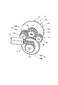
図7は、図4のVII−VII断面図であり、つまり、第一ギア28、駆動伝達軸52および第二ギア29の各軸線を通る側断面図である。なお、図中、符号L1は、駆動伝達軸2Aの軸線とも一致している。また、第一ギア28、駆動伝達軸52および第二ギア29の各軸線は平行であり、各軸線に直交する方向(図7の左右方向)が、揺動ユニット27の揺動方向となっている。
この図に示すように、回動入力ギア12Aと揺動入力ギア52Aとは、駆動伝達軸52の軸線L1に沿う上下方向に間隔を空けて同軸配置されており、回動入力ギア12Aが、第一ギア28の下側ギア28Aおよび第二ギア29の間に配置され、揺動入力ギア52Aが、第一ギア28の上側ギア28Bの側方に配置される。
Next, the layout of each gear will be described in detail.
7 is a cross-sectional view taken along the line VII-VII in FIG. 4, that is, a side cross-sectional view passing through the axes of the first gear 28, the drive transmission shaft 52, and the second gear 29. In the figure, the symbol L1 also coincides with the axis of the drive transmission shaft 2A. In addition, the axes of the first gear 28, the drive transmission shaft 52, and the second gear 29 are parallel, and the direction orthogonal to each axis (the left-right direction in FIG. 7) is the swing direction of the swing unit 27. Yes.
As shown in this figure, the rotation input gear 12A and the swing input gear 52A are coaxially arranged with an interval in the vertical direction along the axis L1 of the drive transmission shaft 52, and the rotation input gear 12A is The swing input gear 52A is disposed between the lower gear 28A of the first gear 28 and the second gear 29, and is disposed on the side of the upper gear 28B of the first gear 28.

この構成により、揺動ユニット27が、図7中、左方向に揺動した場合には、同図7に示すように、第一ギア28の上側ギア28Bが回動入力ギア12Aに噛み合い、第二ギア29は揺動入力ギア52Aから離間する。一方、揺動ユニット27が、図7中、右方向に揺動した場合には、第二ギア29が揺動入力ギア52Aに噛み合い、第一ギア28は回動入力ギア12Aから離間する。これによって、揺動ユニット27の各ギア28,29は、回動入力ギア12Aおよび揺動入力ギア52Aのいずれか一方に選択的に噛合するようになっている。   With this configuration, when the swing unit 27 swings leftward in FIG. 7, the upper gear 28B of the first gear 28 meshes with the rotation input gear 12A, as shown in FIG. The two gears 29 are separated from the swing input gear 52A. On the other hand, when the swing unit 27 swings in the right direction in FIG. 7, the second gear 29 is engaged with the swing input gear 52A, and the first gear 28 is separated from the rotation input gear 12A. As a result, the gears 28 and 29 of the swing unit 27 are selectively meshed with either the rotation input gear 12A or the swing input gear 52A.

第一ギア28および第二ギア29について詳述すると、第一ギア28の下側ギア28Aと第二ギア29とは、同じギア部品が適用されるとともに、被動ギア25の周方向に間隔を空けて同じ高さに配置され、各々のギア28,29が被動ギア25に噛み合っている。
第一ギア28の上側ギア28Bは、下側ギア28Aと同径のギアであって、共通の軸28C(図7参照)を介して下側ギア28Aと一体に連結され、回動入力ギア12Aと同じ高さに位置する。図7に示すように、回動入力ギア12Aは、揺動入力ギア52Aよりも大径に形成されている。このため、第一ギア28は、揺動入力ギア52Aに噛合することがなく、回動入力ギア12Aだけに噛合する。
The first gear 28 and the second gear 29 will be described in detail. The same gear parts are applied to the lower gear 28A and the second gear 29 of the first gear 28, and there is an interval in the circumferential direction of the driven gear 25. The gears 28 and 29 are meshed with the driven gear 25.
The upper gear 28B of the first gear 28 has the same diameter as that of the lower gear 28A, and is integrally connected to the lower gear 28A via a common shaft 28C (see FIG. 7). Located at the same height. As shown in FIG. 7, the rotation input gear 12A is formed to have a larger diameter than the swing input gear 52A. For this reason, the first gear 28 meshes only with the rotation input gear 12A without meshing with the swing input gear 52A.

一方、第二ギア29は、揺動入力ギア52Aの側方、かつ、回動入力ギア12Aの下方に配置されるので、回動入力ギア12Aに噛合することがなく、揺動入力ギア52Aだけに噛合する。
また、本実施形態では、図7に示すように、上方から、カメラユニット11、回動入力ギア12A、揺動入力ギア52Aおよび被動ギア25を上下に間隔を空けて配置し、これらギアの左右に空くスペースを利用して、第一ギア28および第二ギア29を配置している。このため、これらギア群を互いに近接させてコンパクトに配置することができ、ギア機構を小型化することができる。
On the other hand, since the second gear 29 is disposed on the side of the swing input gear 52A and below the rotation input gear 12A, the second gear 29 does not mesh with the rotation input gear 12A, and only the swing input gear 52A. To mesh.
In the present embodiment, as shown in FIG. 7, the camera unit 11, the rotation input gear 12A, the swing input gear 52A, and the driven gear 25 are vertically arranged at intervals from above and left and right of these gears. The first gear 28 and the second gear 29 are arranged using a space that is open. For this reason, these gear groups can be arranged close to each other in a compact manner, and the gear mechanism can be reduced in size.

次にカメラ駆動ユニット10の動作を説明する。
本構成では、上記したように、揺動ユニット27の軸部27Bが、被動ギア25の貫通孔25Cに摩擦嵌合しているので、モータ21の正転/逆転によって被動ギア25が正転/逆転した場合には、被動ギア25との間の摩擦力によって、被動ギア25の回転方向と同方向に揺動ユニット27が回動し、ギア保持体27Aが被動ギア25の軸心を基準にして回転方向へ揺動する。
ここで、図8は、モータ21の正転によって被動ギア25が正転(本実施形態では、図8の矢印で示す時計回り方向に回転)した場合の揺動ユニット27を周辺構成と共に示す図である。また、図9は、モータ21の逆転によって被動ギア25が逆転(図9の矢印で示す反時計回りに回転)した場合を示す図である。また、図中、符号L2は、被動ギア25の軸線である。
Next, the operation of the camera drive unit 10 will be described.
In this configuration, as described above, the shaft portion 27B of the swing unit 27 is frictionally fitted in the through hole 25C of the driven gear 25, so that the driven gear 25 is rotated forward / reversely by the forward / reverse rotation of the motor 21. In the case of reverse rotation, the oscillating unit 27 rotates in the same direction as the rotational direction of the driven gear 25 due to the frictional force with the driven gear 25, and the gear holder 27A is based on the axis of the driven gear 25. Swings in the direction of rotation.
Here, FIG. 8 is a diagram showing the swing unit 27 together with the peripheral configuration when the driven gear 25 rotates in the normal direction (in this embodiment, rotates in the clockwise direction indicated by the arrow in FIG. 8) by the normal rotation of the motor 21. It is. FIG. 9 is a diagram illustrating a case where the driven gear 25 rotates in the reverse direction (rotates counterclockwise as indicated by the arrow in FIG. 9) due to the reverse rotation of the motor 21. Further, in the drawing, a symbol L2 is an axis of the driven gear 25.

モータ21が正転し、被動ギア25が回転(正転)すると、ギア保持体27Aの回転方向への揺動により、図8および前掲図7に示すように、第一ギア28が軸線L1に近づいて回動入力ギア12Aに噛み合う。この場合、第二ギア29は軸線L1から離れるので、揺動入力ギア52Aに噛み合うことがない。
これによって、モータ21の回転力が、被動ギア25および第一ギア28を介して回動入力ギア12Aに伝達され、回動入力ギア12Aの回転によりカメラユニット11が回動する。
一方、モータ21が逆転し、被動ギア25が回転(逆転)すると、ギア保持体27Aの回転方向への揺動により、図9に示すように、第二ギア29が軸線L1に近づいて揺動入力ギア52Aに噛み合う。これによって、モータ21の回転力が、被動ギア25および第二ギア29を介して揺動入力ギア52Aに伝達され、揺動入力ギア52Aの回転によりカメラユニット11が揺動する。
このようにしてモータ21の正転/逆転の切り替えにより、カメラユニット11の回動/揺動を自動的に切り替えることができる。
When the motor 21 rotates forward and the driven gear 25 rotates (forward rotation), the first gear 28 moves to the axis L1 as shown in FIG. 8 and FIG. Approaching and meshing with the rotation input gear 12A. In this case, since the second gear 29 is separated from the axis L1, it does not mesh with the swing input gear 52A.
Thereby, the rotational force of the motor 21 is transmitted to the rotation input gear 12A via the driven gear 25 and the first gear 28, and the camera unit 11 is rotated by the rotation of the rotation input gear 12A.
On the other hand, when the motor 21 rotates in the reverse direction and the driven gear 25 rotates (reverses), the second gear 29 moves closer to the axis L1 as shown in FIG. 9 due to the rotation of the gear holder 27A in the rotation direction. It meshes with the input gear 52A. Thereby, the rotational force of the motor 21 is transmitted to the swing input gear 52A via the driven gear 25 and the second gear 29, and the camera unit 11 swings by the rotation of the swing input gear 52A.
In this way, the rotation / swing of the camera unit 11 can be automatically switched by switching between normal rotation / reverse rotation of the motor 21.

以上説明したように、本実施の形態によれば、単一のモータ21の正転/逆転によって正転/逆転する被動ギア25と、被動ギア25との摩擦接触により被動ギア25の回転方向に揺動するとともに、被動ギア25に噛み合う第一ギア28および第二ギア29を保持する揺動ユニット(揺動部材)27とを備え、揺動ユニット27の一方側への揺動により第一ギア28を回動入力ギア12Aに噛合させてカメラユニット11を回動させるとともに、揺動ユニット27の他方側への揺動により、第二ギア29を揺動入力ギア52Aに噛合させてカメラユニット11を揺動させるようにしたので、単一のモータ21でカメラユニット11の回動と揺動とを切り替えることができる。この場合、モータ21が1個で良いので、従来の2モータの構成に比して、部品点数を低減でき、小型化に有利なカメラ駆動ユニット10を実現することができる。
なお、従来、魚眼レンズなどで視点を動かさずとも広域を見ることができるカメラも存在していたが、魚眼レンズの場合、映像の端が歪んでしまう。これに対し、本構成では、広い範囲を歪みなく鮮明に写すことができるカメラを1モータの安価な構成で実現することが可能になる。
As described above, according to the present embodiment, the driven gear 25 rotates in the rotational direction due to frictional contact between the driven gear 25 and the driven gear 25 that rotates forward / reversely by the normal rotation / reverse rotation of the single motor 21. A swing unit (swing member) 27 that swings and holds the first gear 28 and the second gear 29 that mesh with the driven gear 25 is provided. 28 is engaged with the rotation input gear 12 </ b> A to rotate the camera unit 11, and the second gear 29 is engaged with the swinging input gear 52 </ b> A by swinging the swinging unit 27 to the other side. The camera unit 11 can be switched between rotating and swinging with a single motor 21. In this case, since only one motor 21 is required, the number of parts can be reduced as compared with the conventional two-motor configuration, and the camera drive unit 10 that is advantageous for downsizing can be realized.
Conventionally, there are cameras that can see a wide area without moving the viewpoint with a fisheye lens or the like, but in the case of a fisheye lens, the edge of the image is distorted. On the other hand, in this configuration, it is possible to realize a camera that can clearly capture a wide range without distortion with an inexpensive configuration of one motor.

また、本構成では、回動入力ギア12Aの回転でカメラユニット11を回動させるとともに、揺動入力ギア52Aの回転でカメラユニット11を揺動させるので、回動および揺動の機構を、伝達効率の高いギア機構で構成でき、機構の複雑化も抑えることができる。
また、本構成では、揺動ユニット27を被動ギア25に揺動自在に挿入しているので、被動ギア25と揺動ユニット27の組み立てが容易である。しかも、揺動ユニット27は、被動ギア25の軸心を貫通する貫通孔25Cに挿入される軸部(挿入軸)27Bを有し、この軸部27Bが被動ギア25に摩擦接触して被動ギア25の回転方向に応じて揺動ユニット27を揺動させるので、被動ギア25の回転に応じて揺動ユニット27を揺動させるフリクション機構を簡易かつ少ない部品数で構成でき、これによっても、小型に有利な構成となる。
In this configuration, the rotation of the rotation input gear 12A rotates the camera unit 11, and the rotation of the swing input gear 52A swings the camera unit 11. Therefore, the rotation and swing mechanism is transmitted. It can be configured with a highly efficient gear mechanism, and the complexity of the mechanism can also be suppressed.
Further, in this configuration, since the swing unit 27 is inserted into the driven gear 25 so as to be swingable, the assembly of the driven gear 25 and the swing unit 27 is easy. In addition, the oscillating unit 27 has a shaft portion (insertion shaft) 27B that is inserted into a through hole 25C penetrating the shaft center of the driven gear 25, and this shaft portion 27B comes into frictional contact with the driven gear 25 to cause the driven gear. Since the oscillating unit 27 is oscillated according to the rotation direction of the driven gear 25, the friction mechanism that oscillates the oscillating unit 27 according to the rotation of the driven gear 25 can be configured simply and with a small number of parts. This is an advantageous configuration.

さらに、第一ギア28と第二ギア29とは、被動ギア25の周方向に間隔を空けて配置され、第一ギア28と第二ギア29との間に、回動入力ギア12Aと揺動入力ギア52Aとが同軸上に配置されているので、第一ギア28と第二ギア29との間のスペースを効率よく利用して回動用及び揺動用の入力ギア28,29を配置できる。これにより、これらギア28,29,12A,52Aを近接配置でき、効率よく小型化することができる。
また、カメラユニット11は、Y字型のアーム部53などからなるジンバル機構を介して回転台12に揺動自在に支持され、回転台12に回動入力ギア12Aが設けられ、ジンバル機構への駆動伝達軸52が回動入力ギア12Aを貫通し、その端部に揺動入力ギア52Aが配置されるので、カメラユニット11の回動機構31および揺動機構41を簡易かつコンパクトに形成することができる。これによって、より小型化することができ、部品点数も低減可能である。
このように、小型化でき、部品点数も低減できるので、コスト低減に有利なカメラ駆動ユニット10を実現することが可能になる。
Further, the first gear 28 and the second gear 29 are arranged at an interval in the circumferential direction of the driven gear 25, and swing between the first gear 28 and the second gear 29 and the rotation input gear 12 </ b> A. Since the input gear 52A is coaxially arranged, the input gears 28 and 29 for turning and swinging can be arranged by efficiently using the space between the first gear 28 and the second gear 29. Thereby, these gears 28, 29, 12A, and 52A can be arranged close to each other, and can be efficiently downsized.
The camera unit 11 is swingably supported by the turntable 12 via a gimbal mechanism including a Y-shaped arm portion 53 and the like, and a turn input gear 12A is provided on the turntable 12 to Since the drive transmission shaft 52 penetrates the rotation input gear 12A and the swing input gear 52A is disposed at the end thereof, the rotation mechanism 31 and the swing mechanism 41 of the camera unit 11 can be formed simply and compactly. Can do. As a result, the size can be further reduced, and the number of parts can be reduced.
As described above, since the size can be reduced and the number of parts can be reduced, it is possible to realize the camera drive unit 10 that is advantageous for cost reduction.

<第二実施形態>
図10乃至図12は、第二実施形態に係るカメラ駆動ユニット10の回転台12を周辺構成と共に示している。第二実施形態では、図10に示すように、回転台12の外周部にロック用溝(被係合部)71を設け、揺動ユニット27に、当該揺動ユニット27の揺動位置に応じてロック用溝71に係合するロック部材(回動規制部材)73を設けており、それ以外の構成は第一実施形態と略同様である。
ロック用溝71は、回転台12のベース12Bの外周全体に設けられた凹状溝に形成され、ロック部材73は、揺動ユニット27のギア保持体27Aから立設するピン形状に形成されている。このロック部材73は、揺動ユニット27の揺動により第二ギア29が揺動入力ギア52Aに噛み合った場合に、図11に示すように、ロック用溝71に係合し、第一ギア28が回動入力ギア12Aに噛み合った場合には、図12に示すように、ロック用溝71から待避する位置に設けられている。
<Second embodiment>
10 to 12 show the turntable 12 of the camera drive unit 10 according to the second embodiment together with the peripheral configuration. In the second embodiment, as shown in FIG. 10, a locking groove (engaged portion) 71 is provided on the outer peripheral portion of the turntable 12, and the swing unit 27 is set according to the swing position of the swing unit 27. A locking member (rotation restricting member) 73 that engages with the locking groove 71 is provided, and the other configuration is substantially the same as in the first embodiment.
The locking groove 71 is formed in a concave groove provided on the entire outer periphery of the base 12 </ b> B of the turntable 12, and the locking member 73 is formed in a pin shape standing from the gear holder 27 </ b> A of the swing unit 27. . When the second gear 29 meshes with the swing input gear 52A by the swing of the swing unit 27, the lock member 73 engages with the lock groove 71 as shown in FIG. Is engaged with the rotation input gear 12A, as shown in FIG.

このため、モータ21が正転し、第一ギア28が回動入力ギア12Aに噛み合っている場合には、回転台12の回転が妨げられないので、第一実施形態と同様に、回動入力ギア12Aの回転によりカメラユニット11を回動させることができる。
一方、モータ21が逆転し、第二ギア29が揺動入力ギア52Aに噛み合っている場合には、ロック部材73がロック用溝71に係合するので、回転台12の回転が規制される。このため、カメラユニット11が揺動している場合に、回転台12が回転してしまう事態を確実に防止することができる。
このように、本実施形態では、揺動ユニット27に、カメラユニット11を揺動させる側に揺動した場合に、ロック用溝(被係合部)71に係合して回転台12の回動を規制するロック部材(回動規制部材)73を設けたので、第一実施形態の各種効果に加えて、カメラユニット11の揺動時にカメラユニット11が回動してしまう事態を確実に防止することが可能になる。
For this reason, when the motor 21 rotates forward and the first gear 28 meshes with the rotation input gear 12A, the rotation of the turntable 12 is not hindered. The camera unit 11 can be rotated by the rotation of the gear 12A.
On the other hand, when the motor 21 rotates in the reverse direction and the second gear 29 meshes with the swing input gear 52A, the lock member 73 engages with the lock groove 71, so that the rotation of the turntable 12 is restricted. For this reason, when the camera unit 11 is rocking | swiveling, the situation where the turntable 12 rotates can be prevented reliably.
Thus, in this embodiment, when the swing unit 27 swings to the side on which the camera unit 11 is swung, it engages with the locking groove (engaged portion) 71 and rotates the turntable 12. Since the lock member (rotation restricting member) 73 for restricting the movement is provided, in addition to the various effects of the first embodiment, it is possible to reliably prevent the camera unit 11 from rotating when the camera unit 11 swings. It becomes possible to do.

上述した実施形態は、あくまで本発明の一態様に過ぎず、本発明の範囲内で任意に変形が可能である。例えば、上述の実施形態において、回動機構31および揺動機構41に、公知の回動機構や揺動機構(回転−揺動変換機構)を適用しても良い。さらに、上述の実施形態では、カメラユニット11を回動および揺動させるカメラ駆動ユニット10に本発明を適用する場合を説明したが、カメラユニット11以外のユニット(被装着ユニット)を装着しても良い。つまり、本発明は、公知の様々なユニットを回動および揺動させる回動・揺動装置に広く適用しても良い。   The above-described embodiment is merely one aspect of the present invention, and can be arbitrarily modified within the scope of the present invention. For example, in the above-described embodiment, a known rotation mechanism or swing mechanism (rotation-swing conversion mechanism) may be applied to the rotation mechanism 31 and the swing mechanism 41. Furthermore, in the above-described embodiment, the case where the present invention is applied to the camera drive unit 10 that rotates and swings the camera unit 11 has been described. good. That is, the present invention may be widely applied to a rotation / oscillation device that rotates and swings various known units.

10 カメラ駆動ユニット(回動・揺動装置)
11 カメラユニット
12 回転台
12A 回動入力ギア
21 モータ
25 被動ギア
25C 貫通孔
27 揺動ユニット(揺動部材、フリクション機構)
27B 軸部(挿入軸)
28 第一ギア
29 第二ギア
31 回動機構
41 揺動機構(回転−揺動変換機構)
52 駆動伝達軸
52A 揺動入力ギア
71 ロック用溝(被係合部)
73 ロック部材(回動規制部材)
10 Camera drive unit (turning / swinging device)
DESCRIPTION OF SYMBOLS 11 Camera unit 12 Turntable 12A Rotation input gear 21 Motor 25 Driven gear 25C Through-hole 27 Oscillation unit (oscillation member, friction mechanism)
27B Shaft (insertion shaft)
28 First gear 29 Second gear 31 Rotating mechanism 41 Oscillating mechanism (rotation-oscillating conversion mechanism)
52 Drive transmission shaft 52A Oscillating input gear 71 Locking groove (engaged portion)
73 Locking member (rotation restricting member)

Claims (6)

所定のユニットを回動させる回動機構と前記ユニットを揺動させる揺動機構とを備える回動・揺動装置において、
単一のモータの正転/逆転によって正転/逆転する被動ギアと、
前記被動ギアとの摩擦接触により前記被動ギアの回転方向に応じて一方側/他方側へ揺動するとともに、前記被動ギアに噛み合う第一ギアおよび第二ギアを保持する揺動部材とを備え、
前記回動機構は、前記揺動部材が一方側または他方側へ揺動した場合に、前記第一ギアが噛合する回動入力ギアを有し、この入力ギアの回転で前記ユニットを回動させ、
前記揺動機構は、前記揺動部材が他方側または一方側へ揺動した場合に、前記第二ギアが噛合する揺動入力ギアを有し、この入力ギアの回転で前記ユニットを揺動させる回転−揺動変換機構であることを特徴とする回動・揺動装置
In a rotation / oscillation device comprising a rotation mechanism for rotating a predetermined unit and a swing mechanism for swinging the unit,
A driven gear that rotates forward / reverse by forward / reverse rotation of a single motor;
A rocking member holding a first gear and a second gear meshing with the driven gear while swinging to one side / the other side according to the rotation direction of the driven gear by frictional contact with the driven gear;
The rotation mechanism has a rotation input gear that meshes with the first gear when the swing member swings to one side or the other side, and rotates the unit by rotating the input gear. ,
The swing mechanism has a swing input gear that meshes with the second gear when the swing member swings to the other side or one side, and the unit is swung by the rotation of the input gear. Rotation / oscillation device characterized by being a rotation-oscillation conversion mechanism
前記揺動部材は、前記被動ギアに揺動自在に挿入されていることを特徴とする請求項1に記載の回動・揺動装置。   The rotation / oscillation device according to claim 1, wherein the oscillation member is inserted into the driven gear so as to freely swing. 前記揺動部材は、前記被動ギアの軸心を貫通する貫通孔に挿入される挿入軸を有し、この挿入軸が前記被動ギアに摩擦接触して前記被動ギアの回転方向に応じて前記揺動部材を揺動させることを特徴とする請求項2に記載の回動・揺動装置。   The swing member has an insertion shaft that is inserted into a through-hole that penetrates the shaft center of the driven gear, and the insertion shaft is brought into frictional contact with the driven gear, and the swinging member is rotated according to the rotation direction of the driven gear. The rotating / swinging device according to claim 2, wherein the moving member is oscillated. 前記第一ギアと前記第二ギアとは、前記被動ギアの周方向に間隔を空けて配置され、前記第一ギアと前記第二ギアとの間に、前記回動入力ギアと前記揺動入力ギアとが同軸上に配置されていることを特徴とする請求項1乃至3のいずれか一項に記載の回動・揺動装置。   The first gear and the second gear are arranged at an interval in the circumferential direction of the driven gear, and the rotation input gear and the swing input are between the first gear and the second gear. The rotation / oscillation device according to any one of claims 1 to 3, wherein the gear and the gear are arranged coaxially. 前記ユニット本体は、ジンバル機構を介して回転台に揺動自在に支持され、前記回転台に前記回動入力ギアが設けられ、前記ジンバル機構への駆動伝達軸が前記回動入力ギアを貫通し、その端部に前記揺動入力ギアが配置されることを特徴とする請求項4に記載の回動・揺動装置。   The unit main body is swingably supported by a turntable via a gimbal mechanism, and the turn input gear is provided on the turntable, and a drive transmission shaft to the gimbal mechanism passes through the turn input gear. 5. The rotation / oscillation device according to claim 4, wherein the oscillation input gear is disposed at an end thereof. 前記回転台の外周部に被係合部を設け、前記揺動部材に、当該揺動部材が前記ユニットを揺動させる側に揺動した場合に、前記被係合部に係合して前記回転台の回動を規制する回動規制部材を有することを特徴とする請求項5に記載の回動・揺動装置。   An engaged portion is provided on an outer peripheral portion of the turntable, and when the swinging member swings to the swinging side of the unit, the swinging member is engaged with the engaged portion and the 6. The turning / swinging device according to claim 5, further comprising a turning restriction member for restricting turning of the turntable.
JP2012151344A 2012-07-05 2012-07-05 Rotating/swinging device Pending JP2014013346A (en)

Priority Applications (1)

Application Number Priority Date Filing Date Title
JP2012151344A JP2014013346A (en) 2012-07-05 2012-07-05 Rotating/swinging device

Applications Claiming Priority (1)

Application Number Priority Date Filing Date Title
JP2012151344A JP2014013346A (en) 2012-07-05 2012-07-05 Rotating/swinging device

Publications (1)

Publication Number Publication Date
JP2014013346A true JP2014013346A (en) 2014-01-23

Family

ID=50109056

Family Applications (1)

Application Number Title Priority Date Filing Date
JP2012151344A Pending JP2014013346A (en) 2012-07-05 2012-07-05 Rotating/swinging device

Country Status (1)

Country Link
JP (1) JP2014013346A (en)

Cited By (1)

* Cited by examiner, † Cited by third party
Publication number Priority date Publication date Assignee Title
CN105472208A (en) * 2014-09-09 2016-04-06 鸿富锦精密工业(深圳)有限公司 Video camera and steering mechanism thereof

Cited By (2)

* Cited by examiner, † Cited by third party
Publication number Priority date Publication date Assignee Title
CN105472208A (en) * 2014-09-09 2016-04-06 鸿富锦精密工业(深圳)有限公司 Video camera and steering mechanism thereof
CN105472208B (en) * 2014-09-09 2019-01-18 鸿富锦精密工业(深圳)有限公司 Video camera and its steering mechanism

Similar Documents

Publication Publication Date Title
JP6080066B1 (en) Pan / tilt drive device and camera device
JP2008167257A (en) Pan/tilt device
JP4031678B2 (en) Rotating camera device
JP5223597B2 (en) Tilt mechanism of surveillance camera device
US11372317B2 (en) Camera supporting device and camera therewith
TWI547665B (en) Camera and rotating structure
JP3886857B2 (en) Camera turning device
JP2009210207A (en) Louver device
JP2015021411A (en) Electric fan oscillation apparatus and electric fan using the same
JP2017085231A (en) Imaging device
JP2014069578A (en) On-vehicle electronic equipment
JP4586000B2 (en) Cradle with pan head function
JP2014013346A (en) Rotating/swinging device
JP2013125169A (en) Lens shift device and projector
JP2015035735A (en) Camera device and filter unit
JP6420113B2 (en) Door drive device for refrigerator
JP4555245B2 (en) Lens shift mechanism and projection display device
JP2011179593A (en) Power transmission device
JP6605306B2 (en) Compound drive
JP6075996B2 (en) The camera module
JP4017442B2 (en) Video camera equipment
JP2004197822A (en) Backlash eliminator, gear type rotation transmission device, and camera turning device
JP3973336B2 (en) Video camera
JP2024029738A (en) Rotating mechanism and electric fan with it
JP2015152215A (en) damper device