JP2014009707A - Solid lubrication rolling bearing - Google Patents
Solid lubrication rolling bearing Download PDFInfo
- Publication number
- JP2014009707A JP2014009707A JP2012144549A JP2012144549A JP2014009707A JP 2014009707 A JP2014009707 A JP 2014009707A JP 2012144549 A JP2012144549 A JP 2012144549A JP 2012144549 A JP2012144549 A JP 2012144549A JP 2014009707 A JP2014009707 A JP 2014009707A
- Authority
- JP
- Japan
- Prior art keywords
- shield plate
- rolling bearing
- peripheral edge
- bearing
- solid
- Prior art date
- Legal status (The legal status is an assumption and is not a legal conclusion. Google has not performed a legal analysis and makes no representation as to the accuracy of the status listed.)
- Granted
Links
Images


Classifications
-
- F—MECHANICAL ENGINEERING; LIGHTING; HEATING; WEAPONS; BLASTING
- F16—ENGINEERING ELEMENTS AND UNITS; GENERAL MEASURES FOR PRODUCING AND MAINTAINING EFFECTIVE FUNCTIONING OF MACHINES OR INSTALLATIONS; THERMAL INSULATION IN GENERAL
- F16C—SHAFTS; FLEXIBLE SHAFTS; ELEMENTS OR CRANKSHAFT MECHANISMS; ROTARY BODIES OTHER THAN GEARING ELEMENTS; BEARINGS
- F16C33/00—Parts of bearings; Special methods for making bearings or parts thereof
- F16C33/72—Sealings
- F16C33/76—Sealings of ball or roller bearings
- F16C33/78—Sealings of ball or roller bearings with a diaphragm, disc, or ring, with or without resilient members
- F16C33/784—Sealings of ball or roller bearings with a diaphragm, disc, or ring, with or without resilient members mounted to a groove in the inner surface of the outer race and extending toward the inner race
- F16C33/7843—Sealings of ball or roller bearings with a diaphragm, disc, or ring, with or without resilient members mounted to a groove in the inner surface of the outer race and extending toward the inner race with a single annular sealing disc
- F16C33/7846—Sealings of ball or roller bearings with a diaphragm, disc, or ring, with or without resilient members mounted to a groove in the inner surface of the outer race and extending toward the inner race with a single annular sealing disc with a gap between the annular disc and the inner race
-
- F—MECHANICAL ENGINEERING; LIGHTING; HEATING; WEAPONS; BLASTING
- F16—ENGINEERING ELEMENTS AND UNITS; GENERAL MEASURES FOR PRODUCING AND MAINTAINING EFFECTIVE FUNCTIONING OF MACHINES OR INSTALLATIONS; THERMAL INSULATION IN GENERAL
- F16C—SHAFTS; FLEXIBLE SHAFTS; ELEMENTS OR CRANKSHAFT MECHANISMS; ROTARY BODIES OTHER THAN GEARING ELEMENTS; BEARINGS
- F16C19/00—Bearings with rolling contact, for exclusively rotary movement
- F16C19/02—Bearings with rolling contact, for exclusively rotary movement with bearing balls essentially of the same size in one or more circular rows
- F16C19/04—Bearings with rolling contact, for exclusively rotary movement with bearing balls essentially of the same size in one or more circular rows for radial load mainly
- F16C19/06—Bearings with rolling contact, for exclusively rotary movement with bearing balls essentially of the same size in one or more circular rows for radial load mainly with a single row or balls
Abstract
Description
この発明は、固体潤滑剤によって軸受内部を潤滑するようにした転がり軸受、即ち固体潤滑転がり軸受に関し、例えばフィルム延伸機のテンタクリップを支持する軸受に利用される。 The present invention relates to a rolling bearing in which the inside of the bearing is lubricated by a solid lubricant, that is, a solid lubricated rolling bearing, and is used, for example, as a bearing for supporting a tenter clip of a film stretching machine.
フィルム延伸機はビニールなどの延伸材を加熱溶融し薄く引き延ばす機械であり、その延伸材を挟むクリップがテンタクリップである(特許文献1)。延伸ラインの両側に進行方向に向かって次第に間隔が広くなるようにガイドレールが設置され、そのガイドレールにそれぞれガイドローラーを介してテンタクリップが走行自在に搭載される。両側のテンタクリップにより延伸材の両側縁を挟んだ状態で走行させると、延伸材が幅方向に薄く引き延ばされる。前記のガイドローラーには外輪をローラーとして使用する転がり軸受が用いられる。 A film stretching machine is a machine that heats and melts a stretched material such as vinyl and stretches it thinly, and a clip that sandwiches the stretched material is a tenter clip (Patent Document 1). Guide rails are installed on both sides of the drawing line so that the distance gradually increases in the traveling direction, and tenter clips are mounted on the guide rails via guide rollers so as to be able to run. When running with the tenter clips on both sides sandwiching both side edges of the stretched material, the stretched material is stretched thinly in the width direction. The guide roller is a rolling bearing that uses an outer ring as a roller.
前記テンタクリップが使用される雰囲気温度が150〜250℃である場合は、転がり軸受の潤滑には、耐熱性のあるグリース、例えばフッ素グリースが用いられ、シール材として鋼板製のシールド板やフッ素ゴムが用いられる。 When the atmospheric temperature in which the tenter clip is used is 150 to 250 ° C., heat-resistant grease, for example, fluorine grease is used for lubrication of the rolling bearing, and a steel plate shield plate or fluorine rubber is used as a sealing material. Is used.
延伸材がPEEK(ポリエーテル・エーテル・ケトン)樹脂、PI(ポリイミド)樹脂等の場合は、雰囲気温度が超高温(〜400℃)となるので、転がり軸受の潤滑には固体潤滑方式が採用される(特許文献2)。 When the stretched material is PEEK (polyether, ether, ketone) resin, PI (polyimide) resin, etc., the ambient temperature becomes extremely high (up to 400 ° C), so a solid lubrication system is used for lubrication of rolling bearings. (Patent Document 2).
固体潤滑方式の転がり軸受、即ち固体潤滑転がり軸受は、例えば、保持器の表面を固体潤滑剤又はそれを含む複合材によって形成したもの、転動体間に固体潤滑剤によって形成されたセパレータを介装したものがある。この場合の固体潤滑剤としては、グラファイト、二硫化タングステン、二硫化モリブデンなどがある。 Solid lubrication type rolling bearings, that is, solid lubrication rolling bearings, for example, have a cage surface formed by a solid lubricant or a composite material containing the same, and a separator formed by a solid lubricant between rolling elements. There is what I did. Examples of the solid lubricant in this case include graphite, tungsten disulfide, and molybdenum disulfide.
転がり軸受には、外部からの塵埃や異物の侵入を防止するために、内外輪の間にシールド板が設けられる。その構造は添付の図19に示したようなものであり、シールド板1はその外周縁部2を外輪3の内径面に設けられた取付け溝4に嵌合固定される。
The rolling bearing is provided with a shield plate between the inner and outer rings in order to prevent dust and foreign matter from entering from the outside. The structure is as shown in FIG. 19 attached, and the
シールド板1の内周縁部5が内向に屈曲され、その内周縁部5が内輪6の外径面に設けられたシール溝7に対し所定のすき間をおいて臨む。内輪6と外輪3の各軌道溝間に多数の転動体8が介在され、保持器9によって所定の間隔に保持される。内周縁部5とシール溝7とのすき間、内周縁部5と肩部外周部6aとの間のすき間δ等によってラビリンスシールが形成される。
The inner peripheral edge 5 of the
しかし、固体潤滑転がり軸受は、軸受の運転と共に固体潤滑剤の摩耗粉が発生するので、その摩耗粉がシールド板1のすき間δを通って軸受外部に飛散することが避けられない。
However, since the solid lubricant rolling bearing generates wear powder of the solid lubricant with the operation of the bearing, it is inevitable that the wear powder is scattered outside the bearing through the gap δ of the
フィルム延伸機においては、延伸材であるフィルムに異物が付着することは厳禁とされるが、従来のシールド板1は非接触タイプでありすき間δが存在するため、摩耗粉の飛散を防止又は抑制する効果が不十分である問題があった。
In the film stretching machine, it is strictly forbidden for foreign matter to adhere to the film as the stretching material, but the
そこで、この発明は、固体潤滑転がり軸受において、固体潤滑剤の摩耗粉を軸受内部に閉じ込めることにより、外部への飛散を防止又は抑制することを課題とする。 In view of this, an object of the present invention is to prevent or suppress scattering to the outside in a solid lubricated rolling bearing by confining the wear powder of the solid lubricant inside the bearing.
前記の課題を解決するために、この発明に係る固体潤滑転がり軸受は、固体潤滑転がり軸受の内部において発生する固体潤滑剤の摩耗粉の軸受外部への飛散を防止又は抑制するために、前記転がり軸受のいずれか一方の軌道輪の肩部に環状のシールド板の固定側周縁部を取り付け、そのシールド板の自由側周縁部を他方の軌道輪の肩部に接近又は接触させた固体潤滑転がり軸受において、前記シールド板の固定側周縁部と自由側周縁部の間の部分を屈曲して軸受内方に向けて開放され、底面が軸受幅外部に突き出した周溝を形成し、前記周溝により摩耗粉の滞留部を形成したものである。 In order to solve the above-described problems, a solid lubricated rolling bearing according to the present invention is provided with the above-described rolling in order to prevent or suppress the scattering of solid lubricant wear powder generated inside the solid lubricated rolling bearing to the outside of the bearing. A solid lubricated rolling bearing in which the fixed peripheral edge of the annular shield plate is attached to the shoulder of one of the bearing rings, and the free peripheral edge of the shield plate is brought close to or in contact with the shoulder of the other bearing ring In this case, a portion between the fixed peripheral edge portion and the free peripheral edge portion of the shield plate is bent and opened toward the inside of the bearing, and a circumferential groove with a bottom surface protruding outside the bearing width is formed. This is the one where a staying part of the wear powder is formed.
シールド板に深い周溝を形成することにより容積の大きな滞留部が形成されるので、軸受内部で発生する摩耗粉を十分に滞留させことができ、外部への飛散を防止又は抑制する。 By forming a deep circumferential groove in the shield plate, a large volume retention portion is formed, so that abrasion powder generated inside the bearing can be sufficiently retained, and scattering to the outside is prevented or suppressed.
また、前記の課題を解決するために、この発明に係る固体潤滑転がり軸受は、固体潤滑転がり軸受の内部において発生する固体潤滑剤の摩耗粉の軸受外部への飛散を防止又は抑制するために、前記転がり軸受のいずれか一方の軌道輪の肩部に環状のシールド板の固定側周縁部を取り付け、そのシールド板の自由側周縁部を他方の軌道輪の肩部に接近又は接触させた固体潤滑転がり軸受において、前記シールド板の固定側周縁部と自由側周縁部の間の部分を屈曲して軸受内部方向に向けて開放された周溝を形成し、前記周溝を形成する自由側周縁部の先端に浅い折返し屈曲部を設け、その屈曲部を含む前記周溝により摩耗粉の滞留部を形成したものである。 Further, in order to solve the above-mentioned problems, the solid lubricated rolling bearing according to the present invention is configured to prevent or suppress scattering of wear powder of solid lubricant generated outside the solid lubricated rolling bearing to the outside of the bearing. Solid lubrication in which a fixed peripheral edge of an annular shield plate is attached to the shoulder of one of the rolling bearings, and the free peripheral edge of the shield plate is brought close to or in contact with the shoulder of the other bearing ring In a rolling bearing, a free side peripheral portion forming the peripheral groove by bending a portion between the fixed side peripheral portion and the free side peripheral portion of the shield plate to form a peripheral groove opened toward the bearing internal direction. A shallow bent portion is provided at the front end of each of the two, and a stay portion for wear powder is formed by the circumferential groove including the bent portion.
この場合は、周溝の深さは問わないが、周溝の自由側周縁部の先端に浅い折返し屈曲部を設け、その屈曲部を含む周溝により摩耗粉の滞留部を形成するものである。折返し屈曲部により周溝の容積の増大が図られ、同時に滞留部に留まった摩耗粉の逸脱を防止する。 In this case, the depth of the circumferential groove does not matter, but a shallow folded bent portion is provided at the distal end of the peripheral edge of the free side of the circumferential groove, and a stay portion for wear powder is formed by the circumferential groove including the bent portion. . The volume of the circumferential groove is increased by the folded portion, and at the same time, the wear powder staying in the staying portion is prevented from escaping.
前記の折返し屈曲部の先端にさらに深く折り返した折返し屈曲を設けた構成や、周溝の底面が軸受幅外部に突き出している構成をとることにより、周溝の容積の増大、摩耗粉の逸脱防止を一層確実に図ることができる。 By adopting a configuration in which a folded portion that is folded deeper at the tip of the folded portion is provided, or a configuration in which the bottom surface of the circumferential groove protrudes outside the bearing width, the volume of the circumferential groove is increased and wear powder is prevented from deviating. Can be achieved more reliably.
さらに、前記の課題を解決するために、この発明に係る固体潤滑転がり軸受は、固体潤滑転がり軸受の内部において発生する固体潤滑剤の摩耗粉の軸受外部への飛散を防止又は抑制するために、前記転がり軸受のいずれか一方の軌道輪の肩部に環状のシールド板の固定側周縁部を取り付け、そのシールド板の自由側周縁部を他方の軌道輪の肩部に接近又は接触させた固体潤滑転がり軸受において、前記シールド板と軌道輪の協同によって摩耗粉の滞留部を形成した構成をとることもできる。 Furthermore, in order to solve the above-described problem, the solid lubricated rolling bearing according to the present invention is configured to prevent or suppress scattering of abrasion powder of solid lubricant generated inside the solid lubricated rolling bearing to the outside of the bearing. Solid lubrication in which a fixed peripheral edge of an annular shield plate is attached to the shoulder of one of the rolling bearings, and the free peripheral edge of the shield plate is brought close to or in contact with the shoulder of the other bearing ring In the rolling bearing, it is possible to adopt a configuration in which a retaining portion for wear powder is formed by the cooperation of the shield plate and the race.
前記シールド板と軌道輪の協同によって形成される前記滞留部としては以下の構成がある。 The staying portion formed by the cooperation of the shield plate and the raceway has the following configuration.
(1)前記シールド板を金属製の外周部材とこれに一体化された耐熱性軟質素材製の内周部材とによって構成し、前記外周部材を前記一方の軌道輪に取り付けるとともに、前記内周部材を対向する他方の軌道輪のシール溝に摺接させることにより、前記シールド板の内側に当該滞留部を形成する構成。 (1) The shield plate is constituted by a metal outer peripheral member and an inner peripheral member made of a heat-resistant soft material integrated therewith, and the outer peripheral member is attached to the one race ring, and the inner peripheral member A structure in which the staying portion is formed inside the shield plate by sliding contact with a seal groove of the other bearing ring facing each other.
(2)前記シールド板の自由側周縁部を対向する軌道輪のシール溝上に臨ませ、前記自由側周縁部の軸方向外側面に所要の軸方向のすき間をおいて対向する環状の蓋部材を当該軌道輪の肩部に設けることにより、前記シールド板と蓋部材の内側に当該滞留部を形成する構成。 (2) An annular lid member facing the free peripheral edge of the shield plate over the seal groove of the opposite raceway and facing the axially outer surface of the free peripheral edge with a required axial clearance. The structure which forms the said retention part inside the said shield board and a cover member by providing in the shoulder part of the said bearing ring.
(3)前記自由側周縁部を軸方向内向きに屈曲し、その屈曲部の先端部を対向した軌道輪の肩部外側面に設けられた溝に臨ませることによりラビリンス構造を形成し、そのシールド板とラビリンス構造部の内側に当該滞留部を形成する構成。 (3) A labyrinth structure is formed by bending the free peripheral edge inward in the axial direction, and facing the tip of the bent portion into a groove provided on the outer surface of the shoulder of the facing race, The structure which forms the said retention part inside a shield board and a labyrinth structure part.
(4)前記軌道輪に設けられたシール溝の底面に凹入溝を設け、この凹入部に摩耗粉を滞留させる構成。 (4) A configuration in which a recessed groove is provided in the bottom surface of the seal groove provided in the raceway, and wear powder is retained in the recessed portion.
前記シールド板は、ステンレス鋼や、フェライト系やオーステナイト系、Fe基超合金、Co又はNi基合金、金属間化合物(FeAl等)などの耐熱鋼、セラミックスによって形成することができるが、コストや錆、延性などを考慮した場合、SUS301や304がより好ましい。 The shield plate can be formed of stainless steel, ferritic or austenitic, Fe-based superalloy, Co or Ni-based alloy, heat-resistant steel such as intermetallic compounds (FeAl, etc.), ceramics, but cost and rust. In consideration of ductility, SUS301 and 304 are more preferable.
前記固体潤滑転がり軸受の内輪、外輪、転動体のうち少なくともいずれかは、軸受用鋼、セラミックス等によって成形することができる。軸受用鋼としては、高炭素クロム軸受鋼、浸炭鋼、耐熱鋼、ステンレス鋼、合金工具鋼、高速度工具鋼、クロム鋼、クロムモリブデン鋼等が採用できる。ステンレス鋼は、マルテンサイト系ステンレス鋼等が採用できる。セラミックスとしては、窒化ケイ素やサイアロン、ジルコニア、炭化ケイ素等が採用できる。また、ステンレス鋼や軸受用鋼を母材といて軸受構成部品の表層に適当な硬化層を形成しても良い。硬化層としては浸炭、浸炭窒化、窒化層等などが採用できる。 At least one of the inner ring, outer ring, and rolling element of the solid lubricated rolling bearing can be formed of bearing steel, ceramics, or the like. As the bearing steel, high carbon chrome bearing steel, carburized steel, heat resistant steel, stainless steel, alloy tool steel, high speed tool steel, chrome steel, chrome molybdenum steel and the like can be adopted. As the stainless steel, martensitic stainless steel or the like can be adopted. As the ceramic, silicon nitride, sialon, zirconia, silicon carbide, or the like can be used. Further, an appropriate hardened layer may be formed on the surface layer of the bearing component using stainless steel or bearing steel as a base material. As the hardened layer, carburizing, carbonitriding, nitriding layer or the like can be adopted.
以上のように、この発明によれば、固体潤滑転がり軸受の内部で発生する固体潤滑剤の摩耗粉をシールド板自体に設けた滞留部又はシールド板と軌道輪との協同によって形成された滞留部に閉じ込めることにより、摩耗粉の外部への飛散を防止又は抑制することができる。 As described above, according to the present invention, the stay portion formed by the cooperation of the shield plate and the race ring or the stay portion provided in the shield plate itself with the abrasion powder of the solid lubricant generated inside the solid lubricant rolling bearing. By confining in, it is possible to prevent or suppress the scattering of the wear powder to the outside.
以下、この発明の実施の形態を添付図面に基づいて説明する。
[実施形態1]
Embodiments of the present invention will be described below with reference to the accompanying drawings.
[Embodiment 1]
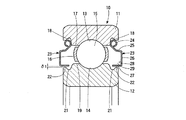
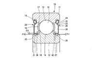
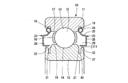
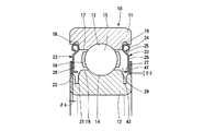
図1に示した実施形態1に係る転がり軸受10は、使用時に固定輪となる外輪11、その外輪11に対向した内輪12、両者の軌道溝13、14の間に介在された多数の転動体15、各転動体15の間を所定の間隔に保持する保持器16により構成される。
The rolling
外輪11の内径面両側の肩部17にそれぞれ取付け溝18が全周に渡り設けられ、これに対向した内輪12の外径面の肩部19にシール溝21が全周に渡り設けられる。シール溝21の軸方向外側にシール溝21の底面より高く(半径が大きく)、肩部19より低い(半径の小さい)肩部外周縁22が設けられる。
A mounting
図示を省略しているが、この転がり軸受10の潤滑は、固体潤滑方式であり、保持器16の転動体15との接触面に固体潤滑剤又はこれを含んだ複合体による固体潤滑層が設けられる。固体潤滑剤としては、グラファイト、二硫化タングステン又は二硫化モリブデンが使用される。
Although not shown, the rolling
前記の取付け溝18にシールド板23の外周縁部24(特許請求の範囲では「固定側周縁部」と称している。)が嵌合固定される。その外周縁部24に連続した部分が軸方向外向きに屈曲され屈曲部25となっている。その屈曲部25は軸受幅の外方まで延び出し、その先端が内径方向に屈曲され中間部26が形成される。中間部26の内径側の先端が軸方向内向きに屈曲され内周縁部27(特許請求の範囲では「自由側周縁部」と称している。)となっている。
The outer peripheral edge 24 (referred to as “fixed side peripheral edge” in the claims) of the
その内周縁部27が内輪12の前記肩部外周縁22上を経てシール溝21の上方に達する。内周縁部27と肩部外周縁22の間の径方向のすき間δ1は、ラビリンスシールを形成する。すき間δ1は、シールド板23が内輪12に接触することを防止する一方、外部から異物が侵入したり、内部から摩耗粉が外部に飛散したりすることを防止又は抑制する。
The inner
前記の屈曲部25、中間部26及び内周縁部27によって、軸受外方に向け軸受幅よりも外方に突き出した周溝28が全周にわたり形成される。周溝28は前記の中間部26が底面となり、その反対側の軸受内方に向けて開放された形状をなしている。この周溝28の内部が摩耗粉の滞留部29となる。滞留部29の容積は、軸受内部において使用される固体潤滑剤の分量を考慮して適宜決定される。
The
なお、転がり軸受10としては、図示の場合深溝玉軸受を示しているが、複列アンギュラ玉軸受であってもよい。また、使用時において外輪11が固定側軌道輪、内輪12が回転側軌道輪となる構成を示しているが、その反対であってもよい。内輪回転の場合も外輪回転の場合も、シールド板23は外輪11に固定される。
As the rolling
実施形態1の転がり軸受10は以上のようなものであり、テンタクリップの軸受として使用された場合、その潤滑は固体潤滑方式であるので、超高温下であっても潤滑作用に支障を来すことはない。また軸受の運転に伴って発生する固体潤滑剤の摩耗粉は、前記の滞留部29に受け止められ滞留する。また、シール溝21の部分にも滞留する。
The rolling
ラビリンスシールを形成するすき間δ1から外部へ抜け出す摩耗粉を完全に防止することは難しいが、すき間δ1の大きさを十分小さくすることにより、その抜け出しを防止又は抑制することができる。 Although it is difficult to completely prevent the wear powder that escapes from the gap δ1 forming the labyrinth seal to the outside, the gap δ1 can be prevented or suppressed by sufficiently reducing the size of the gap δ1.
以上のように、実施形態1の固体潤滑転がり軸受10においては、固体潤滑剤の摩耗粉の大部分を軸受内部の滞留部29に、一部をシール溝21に滞留させることにより、軸受外部への飛散を防止又は抑制することができる。
[実施形態2]
As described above, in the solid lubricated rolling bearing 10 of the first embodiment, most of the wear powder of the solid lubricant is retained in the retaining
[Embodiment 2]
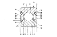
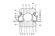
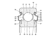
図2に示した実施形態2の固体潤滑転がり軸受10は、前記の実施形態1の場合に比べ、シールド板23の外周縁部24と内周縁部27の間に屈曲形成される周溝28の底面が軸受の幅内にあり、前記の実施形態1の周溝28に比べて浅く形成される。内向きに屈曲された内周縁部27の先端部に浅い折返し屈曲部31が設けられている。
The solid lubricated rolling bearing 10 according to the second embodiment shown in FIG. 2 has a
折返し屈曲部31は、内輪12のシール溝21から肩部19に至る傾斜面32に対し小さいすき間δ2をおいて対向する。すき間δ2はすき間δ1と共にラビリンスシールを形成する。
The folded
屈曲部25、中間部26、内周縁部27及び折返し屈曲部31によって全周に渡る周溝28が形成され、その内側が滞留部29となっている。折返し屈曲部31を設けることにより滞留部29の容積が増え、同時に滞留部29内に留まった摩耗粉の逸脱が防止又は抑制される。その他の構成は実施形態1の場合と同様である。
A
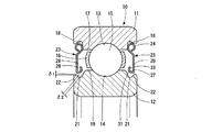
前記図2の変形例として図3に示したように、前記の折返し屈曲部31の先端部にさらに深く折り返したカエリ状の折返し屈曲部33を設けることができる。これにより、滞留部29の容積の一層の増大を図ることができるとともに、摩耗粉の逸脱を一層効果的に防止又は抑制することができる。
[実施形態3]
As shown in FIG. 3 as a modified example of FIG. 2, a fold-like folded
[Embodiment 3]
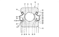
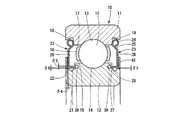
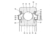
図4に示した実施形態3は、前記の実施形態1の構成に実施形態2の構成を適用したものである。即ち、実施形態1(図1参照)と同様に、シールド板23の屈曲部25は軸受幅の外方まで延び出し、それに応じて内周縁部27も大きく内方に屈曲されている。これにより周溝28の底面は軸受幅よりも外方に突き出し、滞留部29の容積が拡大されている。さらに、実施形態2(図2参照)と同様に内周縁部27の先端に浅く折り返した折返し屈曲部31を設けている。その他の構成は実施形態1の場合と同様である。
In the third embodiment shown in FIG. 4, the configuration of the second embodiment is applied to the configuration of the first embodiment. That is, as in the first embodiment (see FIG. 1), the
図5に示した変形例のように、折返し屈曲部31の先端にカエリ状の深い折返し屈曲部33を設けることができる。図3の場合と同様に、滞留部29の容積の一層の増大を図ることができるとともに、摩耗粉の逸脱を一層効果的に防止又は抑制することができる。
[実施形態4]
As in the modification shown in FIG. 5, a burly deep folded
[Embodiment 4]
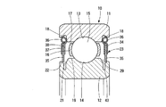
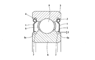
図6に示した実施形態4の固体潤滑転がり軸受10のシールド板23は、鉄等の金属製の外周部材34と耐熱性軟質素材製の内周部材35とによって構成される。外周部材33はパイプ状に巻き曲げられた外周縁部36と軸方向に対向した2枚の挟着片37、38とからなる。外側の挟着片37は外周縁部36に連続して形成される。内側の挟着片38は別部材を溶接によって接合される。
The
前記の内周部材35の外径側のおよそ半分が挟着片37、38間で強固に挟み付けられ、外周部材34と内周部材35が一体化されている。内周部材35の内径側の周縁部は内輪12のシール溝21の底面と肩部外周縁22との間の傾斜面39に接触され、接触型シールを構成する。
Approximately half of the outer peripheral side of the inner
内周部材35を構成する耐熱性軟質素材としては、例えば耐熱性、吸音性に優れたセラミックファイバー等の繊維系断熱材がある。
As the heat resistant soft material constituting the inner
このように実施形態4のシールド板23は、鉄等の金属製の外周部材34と耐熱性軟質素材の内周部材35とによって構成されものであるから、超高温下において使用可能である。また、シールド板23と、その内周部材35を摺接させた内輪12との協同によって接触型シールが構成されるので、外部に対して閉鎖された滞留部29が形成される。このため、軸受内部で発生する摩耗粉をその滞留部29内に閉じ込めることができ、外部への飛散を確実に防止することができる。
[実施形態5]
As described above, the
[Embodiment 5]
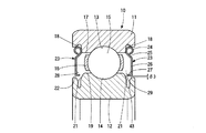
図7に示した実施形態5のシールド板23は、前述の従来例(図18参照)のものと同様に、外周縁部24が外輪11の肩部17に設けられた取付け溝18に嵌合固定される。シールド板23の内周縁部27が内向きに屈曲される。その内周縁部27が内輪12の外径面の肩部外周縁22に対し、径方向の所定のすき間δ3をおいて臨む。シールド板23の全体は軸受の幅内にある。
The
従来の場合は屈曲部25、中間部26及び内周縁部27によって形成される周溝28が浅いこと、及び前記のすき間δ3(図18のすき間δに相当)の存在が摩耗粉の飛散原因となっていた。
In the conventional case, the
これに対しこの実施形態5の場合は、シールド板23の外側において、内輪12の肩部外周縁22に環状の蓋部材41を嵌合固定している。蓋部材41の径方向の幅は、シールド板23の径方向の幅の半分程度であり、シールド板23との間に軸方向に小さいすき間δ3をおいて対向している。そのすき間δ3によってラビリンスシールが構成される。
On the other hand, in the case of the fifth embodiment, an
このように実施形態5の場合は、シールド板23と、内輪12に取り付けられた蓋部材41及びラビリンスシールを構成するすき間δ3との協同により所要の容積をもった滞留部29が構成される。軸受内部において発生した摩耗粉はその滞留部29に閉じ込められる。すき間δ4の大きさを適当に設定することにより、摩耗粉の外部への飛散を防止又は抑制することができる。
[実施形態6]
As described above, in the case of the fifth embodiment, the
[Embodiment 6]
図8に示した実施形態6のシールド板23は、前述の従来例(図18参照)のものと同様に、外周縁部24が外輪11の肩部17に設けられた取付け溝18に嵌合固定される。シールド板23の内周縁部27が内向きに屈曲される。その内周縁部27が内輪12の外径面の肩部外周縁22に対し、径方向の所定のすき間δ3をおいて臨む。シールド板23の全体は軸受の幅内にある。
The
従来の場合(図18参照)は、周溝が浅いこと、及びすき間δの存在が摩耗粉の飛散原因となっていたが、この実施形態6の場合は、内輪12の肩部19の外側面にラビリンス溝42が設けられ、内周縁部27の先端部がそのラビリンス溝42に径方向、周方向に所要のすき間をおいて挿入される。
In the conventional case (see FIG. 18), the circumferential groove is shallow and the presence of the gap δ causes the abrasion powder to be scattered. In the case of the sixth embodiment, the outer surface of the
内周縁部27の先端部とラビリンス溝42のとの間にすき間δ5、δ6によって代表されるすき間が形成される。また、内周縁部27と肩部外周縁22との間には前述のすき間δ3が存在するので、これらのすき間δ3、δ5、δ6等によってラビリンスシールが構成される。
A gap represented by gaps δ5 and δ6 is formed between the tip of the inner
このように実施形態6の場合は、シールド板23と、内輪12側のすき間δ3、δ5、δ6等によるラビリンスシールとの協同により所要の容積をもった滞留部29が構成され、軸受内部において発生した摩耗粉がその滞留部29に閉じ込められる。すき間δ3、δ5、δ6等の大きさを適当に設定することにより、摩耗粉の外部への飛散を防止又は抑制することができる。
As described above, in the case of the sixth embodiment, the
図9に示した変形例は、図8の場合において、周溝28の底面が軸受幅の外方に突き出すように深く形成したもの(図1参照)であり、滞留部29の容積が一層大きくなっている。
The modification shown in FIG. 9 is the one shown in FIG. 8 in which the bottom surface of the
図10に示した他の変形例は、図8の場合において、内輪12の肩部外周縁22に環状の蓋部材41を嵌合固定している(図7参照)。蓋部材41の径方向の幅は、シールド板23の径方向の幅の半分程度であり、シールド板23との間に軸方向に小さいすき間δ4をおいて対向している。そのすき間δ4によってラビリンスシールが構成される。図8の場合に比べ、すき間δ4が増えるのでラビリンスシールによるシールの効果が増大する。
[実施形態7]
In another modification shown in FIG. 10, in the case of FIG. 8, an
[Embodiment 7]
図11に示した実施形態7の固体潤滑転がり軸受10は内輪12のシール溝21の形状を除き、シールド板23の部分を含めその他の構造は前記の従来例(図18参照)の場合と同様である。
The solid lubricated rolling bearing 10 of the seventh embodiment shown in FIG. 11 is the same as that of the conventional example (see FIG. 18) except for the shape of the
この実施形態7の場合は、シール溝21の底面にさらに深く凹入した凹入溝43が設けられる。シールド板23は、前述の従来例(図18参照)のものと同様に、外周縁部24が外輪11の肩部17に設けられた取付け溝18に嵌合固定される。シールド板23の内周縁部27が内向きに屈曲される。その内周縁部27が内輪12の外径面の肩部外周縁22に対し、径方向の所定のすき間δ3をおいて臨む。シールド板23の全体は軸受の幅内にある。
In the case of the seventh embodiment, a recessed
この実施形態7の場合は、シール溝21の底面には前述の凹入溝43が設けられているので、軸受内部からシールド板23側へ移動した摩耗粉は凹入溝43に落下して滞留し、落下しなかった摩耗粉はすき間δ3のラビリンスシールによって外部への飛散が規制される。
In the case of the seventh embodiment, since the
前記シールド板23とすき間δ3の内側の凹入溝43を含む部分が滞留部29となり、軸受内部において発生した摩耗部が凹入溝43を含んだ滞留部29に閉じ込められる。これにより摩耗粉の外部への飛散を抑制することができる。
A portion including the recessed
図12から図17は、図11に示した実施形態7の変形例であり、それぞれ図11の構成を基本にして以下の構成を適用したものである。 12 to 17 are modifications of the seventh embodiment shown in FIG. 11, and the following configuration is applied based on the configuration of FIG.
図12に示した変形例1は図1の構成を、図13に示した変形例2は図4の構成を、図14に示した変形例3は図5の構成を、図15に示した変形例4は図6の構成を、図16に示した変形例5は図7の構成を、図17に示した変形例6は図8の構成をそれぞれ適用したものである。いずれの場合も両方の構成の効果を併有する。
[実施形態8]
12 shows the configuration of FIG. 1, FIG. 13 shows the configuration of FIG. 4, FIG. 14 shows the configuration of FIG. 4, FIG. 14 shows the configuration of FIG. 5, and FIG.
[Embodiment 8]
図18に示した実施形態は、内外輪間に複数の転動体を配列し、固体潤滑剤によって形成されたセパレータ44を転動体間に周方向に複数介装した転がり軸受であり、固体潤滑剤によって形成されたセパレータ44によって徐々に潤滑剤を軌道面に供給するようにしたものである。前記セパレータ44の外面のうち、転動体15と接触する周方向の面を除く内外輪の対向面の少なくとも一面に、セパレータ44の周方向の幅よりも幅の狭い帯金45を一体化している。帯金45を設けることにより、セパレータ44が摩耗しても、転動体15の内外輪からの脱落を防止できる。
The embodiment shown in FIG. 18 is a rolling bearing in which a plurality of rolling elements are arranged between inner and outer rings, and a plurality of
以上の各実施形態におけるシールド板23は、ステンレス鋼や、フェライト系やオーステナイト系、Fe基超合金、Co又はNi基合金、金属間化合物(FeAl等)などの耐熱鋼、セラミックスによって形成することができるが、コストや錆、延性などを考慮した場合、SUS301や304がより好ましい。
The
また、前記固体潤滑転がり軸受10の内輪12、外輪11、転動体15のうち少なくともいずれかは、軸受用鋼、セラミックス等によって成形することができる。軸受用鋼としては、高炭素クロム軸受鋼、浸炭鋼、耐熱鋼、ステンレス鋼、合金工具鋼、高速度工具鋼、クロム鋼、クロムモリブデン鋼等が採用できる。ステンレス鋼は、マルテンサイト系ステンレス鋼等が採用できる。セラミックスとしては、窒化ケイ素やサイアロン、ジルコニア、炭化ケイ素等が採用できる。また、ステンレス鋼や軸受用鋼を母材といて軸受構成部品の表層に適当な硬化層を形成しても良い。硬化層としては浸炭、浸炭窒化、窒化層等などが採用できる。
In addition, at least one of the
δ1〜δ6 すき間
10 転がり軸受
11 外輪
12 内輪
13、14 軌道溝
15 転動体
16 保持器
17 肩部
18 取付け溝
19 肩部
21 シール溝
22 肩部外周縁
23 シールド板
24 外周縁部
25 屈曲部
26 中間部
27 内周縁部
28 周溝
29 滞留部
31 折返し屈曲部
32 傾斜面
33 折返し屈曲部
34 外周部材
35 内周部材
36 外周縁部
37、38 挟着片
39 傾斜面
41 蓋部材
42 ラビリンス溝
43 凹入溝
44 セパレータ
45 帯金
δ1 to
Claims (10)
The solid lubricated rolling bearing according to any one of claims 1 to 9, wherein the rolling bearing is either a deep groove ball bearing or a double row angular ball bearing.
Priority Applications (1)
| Application Number | Priority Date | Filing Date | Title |
|---|---|---|---|
| JP2012144549A JP5973255B2 (en) | 2012-06-27 | 2012-06-27 | Solid lubricated rolling bearing |
Applications Claiming Priority (1)
| Application Number | Priority Date | Filing Date | Title |
|---|---|---|---|
| JP2012144549A JP5973255B2 (en) | 2012-06-27 | 2012-06-27 | Solid lubricated rolling bearing |
Publications (2)
| Publication Number | Publication Date |
|---|---|
| JP2014009707A true JP2014009707A (en) | 2014-01-20 |
| JP5973255B2 JP5973255B2 (en) | 2016-08-23 |
Family
ID=50106596
Family Applications (1)
| Application Number | Title | Priority Date | Filing Date |
|---|---|---|---|
| JP2012144549A Expired - Fee Related JP5973255B2 (en) | 2012-06-27 | 2012-06-27 | Solid lubricated rolling bearing |
Country Status (1)
| Country | Link |
|---|---|
| JP (1) | JP5973255B2 (en) |
Cited By (2)
| Publication number | Priority date | Publication date | Assignee | Title |
|---|---|---|---|---|
| WO2016188400A1 (en) * | 2015-05-26 | 2016-12-01 | 舍弗勒技术股份两合公司 | Bearing |
| IT201900011646A1 (en) * | 2019-07-12 | 2021-01-12 | Skf Ab | THIN SECTION BEARING UNIT |
Citations (4)
| Publication number | Priority date | Publication date | Assignee | Title |
|---|---|---|---|---|
| JPS60114326U (en) * | 1984-01-10 | 1985-08-02 | 日本精工株式会社 | Sealed rolling bearing |
| JPS6487920A (en) * | 1987-09-29 | 1989-04-03 | Toshiba Corp | Rolling bearing |
| JP2009204142A (en) * | 2008-02-29 | 2009-09-10 | Ntn Corp | Rolling bearing |
| JP2012067860A (en) * | 2010-09-24 | 2012-04-05 | Ntn Corp | Solid lubrication rolling bearing |
-
2012
- 2012-06-27 JP JP2012144549A patent/JP5973255B2/en not_active Expired - Fee Related
Patent Citations (4)
| Publication number | Priority date | Publication date | Assignee | Title |
|---|---|---|---|---|
| JPS60114326U (en) * | 1984-01-10 | 1985-08-02 | 日本精工株式会社 | Sealed rolling bearing |
| JPS6487920A (en) * | 1987-09-29 | 1989-04-03 | Toshiba Corp | Rolling bearing |
| JP2009204142A (en) * | 2008-02-29 | 2009-09-10 | Ntn Corp | Rolling bearing |
| JP2012067860A (en) * | 2010-09-24 | 2012-04-05 | Ntn Corp | Solid lubrication rolling bearing |
Cited By (4)
| Publication number | Priority date | Publication date | Assignee | Title |
|---|---|---|---|---|
| WO2016188400A1 (en) * | 2015-05-26 | 2016-12-01 | 舍弗勒技术股份两合公司 | Bearing |
| IT201900011646A1 (en) * | 2019-07-12 | 2021-01-12 | Skf Ab | THIN SECTION BEARING UNIT |
| CN112211899A (en) * | 2019-07-12 | 2021-01-12 | 斯凯孚公司 | Bearing unit with small cross section |
| US11300158B2 (en) | 2019-07-12 | 2022-04-12 | Aktiebolaget Skf | Small cross-section bearing unit |
Also Published As
| Publication number | Publication date |
|---|---|
| JP5973255B2 (en) | 2016-08-23 |
Similar Documents
| Publication | Publication Date | Title |
|---|---|---|
| JP5463687B2 (en) | Rolling bearing | |
| JP2015086940A (en) | Rolling bearing | |
| JP5973255B2 (en) | Solid lubricated rolling bearing | |
| US20160017926A1 (en) | Bearing device with sealing device | |
| JP5835199B2 (en) | Ball bearing | |
| JP6028409B2 (en) | Self-aligning roller bearing with sealing device and manufacturing method thereof | |
| JP2007333011A (en) | Deep groove ball bearing | |
| JP2006312970A (en) | Sealed rolling bearing | |
| JP6275433B2 (en) | Solid lubricated rolling bearing | |
| TW202037822A (en) | Solid-lubricated rolling bearing | |
| JP2009063097A (en) | Rolling bearing | |
| JP2009085277A (en) | Sealing device for rolling bearing and grease-lubricated rolling bearing | |
| JP2015068350A (en) | Wheel bearing seal | |
| JP2013036493A (en) | Rolling bearing | |
| JP2014159840A (en) | Roller bearing | |
| JP2018168871A (en) | Follower bearing | |
| JP2015152125A (en) | Rolling bearing with sealing device | |
| JP5315881B2 (en) | Rolling bearing | |
| JP2007170626A (en) | Sealing device for rolling bearing | |
| JP2007309455A (en) | Ball bearing | |
| JP2019168069A (en) | Sealed bearing | |
| TW202043635A (en) | Solid lubricated rolling bearings | |
| JP2015200351A (en) | Ball bearing | |
| JP2015218786A (en) | Angular contact ball bearing | |
| JP2008002494A (en) | Cage for rolling bearing and rolling bearing using it |
Legal Events
| Date | Code | Title | Description |
|---|---|---|---|
| A621 | Written request for application examination |
Free format text: JAPANESE INTERMEDIATE CODE: A621 Effective date: 20150312 |
|
| A977 | Report on retrieval |
Free format text: JAPANESE INTERMEDIATE CODE: A971007 Effective date: 20160121 |
|
| A131 | Notification of reasons for refusal |
Free format text: JAPANESE INTERMEDIATE CODE: A131 Effective date: 20160126 |
|
| A521 | Written amendment |
Free format text: JAPANESE INTERMEDIATE CODE: A523 Effective date: 20160322 |
|
| A131 | Notification of reasons for refusal |
Free format text: JAPANESE INTERMEDIATE CODE: A131 Effective date: 20160412 |
|
| A521 | Written amendment |
Free format text: JAPANESE INTERMEDIATE CODE: A523 Effective date: 20160608 |
|
| TRDD | Decision of grant or rejection written | ||
| A01 | Written decision to grant a patent or to grant a registration (utility model) |
Free format text: JAPANESE INTERMEDIATE CODE: A01 Effective date: 20160628 |
|
| A61 | First payment of annual fees (during grant procedure) |
Free format text: JAPANESE INTERMEDIATE CODE: A61 Effective date: 20160714 |
|
| R150 | Certificate of patent or registration of utility model |
Ref document number: 5973255 Country of ref document: JP Free format text: JAPANESE INTERMEDIATE CODE: R150 |
|
| LAPS | Cancellation because of no payment of annual fees |