JP5835199B2 - Ball bearing - Google Patents
Ball bearing Download PDFInfo
- Publication number
- JP5835199B2 JP5835199B2 JP2012265531A JP2012265531A JP5835199B2 JP 5835199 B2 JP5835199 B2 JP 5835199B2 JP 2012265531 A JP2012265531 A JP 2012265531A JP 2012265531 A JP2012265531 A JP 2012265531A JP 5835199 B2 JP5835199 B2 JP 5835199B2
- Authority
- JP
- Japan
- Prior art keywords
- ring
- lubricant supply
- supply member
- inner ring
- raceway groove
- Prior art date
- Legal status (The legal status is an assumption and is not a legal conclusion. Google has not performed a legal analysis and makes no representation as to the accuracy of the status listed.)
- Expired - Fee Related
Links
- 239000000314 lubricant Substances 0.000 claims description 84
- 230000002093 peripheral effect Effects 0.000 claims description 46
- 239000004519 grease Substances 0.000 description 10
- 239000010687 lubricating oil Substances 0.000 description 7
- 238000005096 rolling process Methods 0.000 description 5
- 239000012530 fluid Substances 0.000 description 4
- 239000007787 solid Substances 0.000 description 4
- 239000003921 oil Substances 0.000 description 3
- 239000011347 resin Substances 0.000 description 3
- 229920005989 resin Polymers 0.000 description 3
- OKTJSMMVPCPJKN-UHFFFAOYSA-N Carbon Chemical compound [C] OKTJSMMVPCPJKN-UHFFFAOYSA-N 0.000 description 2
- 239000003795 chemical substances by application Substances 0.000 description 2
- 238000010586 diagram Methods 0.000 description 2
- 229910002804 graphite Inorganic materials 0.000 description 2
- 239000010439 graphite Substances 0.000 description 2
- 239000000463 material Substances 0.000 description 2
- 230000004048 modification Effects 0.000 description 2
- 238000012986 modification Methods 0.000 description 2
- CWQXQMHSOZUFJS-UHFFFAOYSA-N molybdenum disulfide Chemical compound S=[Mo]=S CWQXQMHSOZUFJS-UHFFFAOYSA-N 0.000 description 2
- 229910052982 molybdenum disulfide Inorganic materials 0.000 description 2
- 238000003756 stirring Methods 0.000 description 2
- 239000004809 Teflon Substances 0.000 description 1
- 229920006362 Teflon® Polymers 0.000 description 1
- 239000000654 additive Substances 0.000 description 1
- 230000000996 additive effect Effects 0.000 description 1
- 230000005489 elastic deformation Effects 0.000 description 1
- 229920001971 elastomer Polymers 0.000 description 1
- 239000000806 elastomer Substances 0.000 description 1
- 239000007769 metal material Substances 0.000 description 1
- 239000005078 molybdenum compound Substances 0.000 description 1
- 150000002752 molybdenum compounds Chemical class 0.000 description 1
- 239000012466 permeate Substances 0.000 description 1
- 229920001343 polytetrafluoroethylene Polymers 0.000 description 1
- 239000004810 polytetrafluoroethylene Substances 0.000 description 1
- 230000002265 prevention Effects 0.000 description 1
- 238000007789 sealing Methods 0.000 description 1
- 229920001169 thermoplastic Polymers 0.000 description 1
- 229920001187 thermosetting polymer Polymers 0.000 description 1
- 239000004416 thermosoftening plastic Substances 0.000 description 1
Images

Classifications
-
- F—MECHANICAL ENGINEERING; LIGHTING; HEATING; WEAPONS; BLASTING
- F16—ENGINEERING ELEMENTS AND UNITS; GENERAL MEASURES FOR PRODUCING AND MAINTAINING EFFECTIVE FUNCTIONING OF MACHINES OR INSTALLATIONS; THERMAL INSULATION IN GENERAL
- F16C—SHAFTS; FLEXIBLE SHAFTS; ELEMENTS OR CRANKSHAFT MECHANISMS; ROTARY BODIES OTHER THAN GEARING ELEMENTS; BEARINGS
- F16C33/00—Parts of bearings; Special methods for making bearings or parts thereof
- F16C33/30—Parts of ball or roller bearings
- F16C33/66—Special parts or details in view of lubrication
- F16C33/6696—Special parts or details in view of lubrication with solids as lubricant, e.g. dry coatings, powder
-
- F—MECHANICAL ENGINEERING; LIGHTING; HEATING; WEAPONS; BLASTING
- F16—ENGINEERING ELEMENTS AND UNITS; GENERAL MEASURES FOR PRODUCING AND MAINTAINING EFFECTIVE FUNCTIONING OF MACHINES OR INSTALLATIONS; THERMAL INSULATION IN GENERAL
- F16C—SHAFTS; FLEXIBLE SHAFTS; ELEMENTS OR CRANKSHAFT MECHANISMS; ROTARY BODIES OTHER THAN GEARING ELEMENTS; BEARINGS
- F16C19/00—Bearings with rolling contact, for exclusively rotary movement
- F16C19/02—Bearings with rolling contact, for exclusively rotary movement with bearing balls essentially of the same size in one or more circular rows
-
- F—MECHANICAL ENGINEERING; LIGHTING; HEATING; WEAPONS; BLASTING
- F16—ENGINEERING ELEMENTS AND UNITS; GENERAL MEASURES FOR PRODUCING AND MAINTAINING EFFECTIVE FUNCTIONING OF MACHINES OR INSTALLATIONS; THERMAL INSULATION IN GENERAL
- F16C—SHAFTS; FLEXIBLE SHAFTS; ELEMENTS OR CRANKSHAFT MECHANISMS; ROTARY BODIES OTHER THAN GEARING ELEMENTS; BEARINGS
- F16C33/00—Parts of bearings; Special methods for making bearings or parts thereof
- F16C33/30—Parts of ball or roller bearings
- F16C33/58—Raceways; Race rings
- F16C33/583—Details of specific parts of races
-
- F—MECHANICAL ENGINEERING; LIGHTING; HEATING; WEAPONS; BLASTING
- F16—ENGINEERING ELEMENTS AND UNITS; GENERAL MEASURES FOR PRODUCING AND MAINTAINING EFFECTIVE FUNCTIONING OF MACHINES OR INSTALLATIONS; THERMAL INSULATION IN GENERAL
- F16C—SHAFTS; FLEXIBLE SHAFTS; ELEMENTS OR CRANKSHAFT MECHANISMS; ROTARY BODIES OTHER THAN GEARING ELEMENTS; BEARINGS
- F16C33/00—Parts of bearings; Special methods for making bearings or parts thereof
- F16C33/30—Parts of ball or roller bearings
- F16C33/66—Special parts or details in view of lubrication
- F16C33/6603—Special parts or details in view of lubrication with grease as lubricant
- F16C33/6607—Retaining the grease in or near the bearing
- F16C33/6618—Retaining the grease in or near the bearing in a reservoir in the sealing means
-
- F—MECHANICAL ENGINEERING; LIGHTING; HEATING; WEAPONS; BLASTING
- F16—ENGINEERING ELEMENTS AND UNITS; GENERAL MEASURES FOR PRODUCING AND MAINTAINING EFFECTIVE FUNCTIONING OF MACHINES OR INSTALLATIONS; THERMAL INSULATION IN GENERAL
- F16C—SHAFTS; FLEXIBLE SHAFTS; ELEMENTS OR CRANKSHAFT MECHANISMS; ROTARY BODIES OTHER THAN GEARING ELEMENTS; BEARINGS
- F16C33/00—Parts of bearings; Special methods for making bearings or parts thereof
- F16C33/72—Sealings
- F16C33/76—Sealings of ball or roller bearings
- F16C33/78—Sealings of ball or roller bearings with a diaphragm, disc, or ring, with or without resilient members
- F16C33/784—Sealings of ball or roller bearings with a diaphragm, disc, or ring, with or without resilient members mounted to a groove in the inner surface of the outer race and extending toward the inner race
- F16C33/7843—Sealings of ball or roller bearings with a diaphragm, disc, or ring, with or without resilient members mounted to a groove in the inner surface of the outer race and extending toward the inner race with a single annular sealing disc
- F16C33/7846—Sealings of ball or roller bearings with a diaphragm, disc, or ring, with or without resilient members mounted to a groove in the inner surface of the outer race and extending toward the inner race with a single annular sealing disc with a gap between the annular disc and the inner race
- F16C33/785—Bearing shields made of sheet metal
-
- F—MECHANICAL ENGINEERING; LIGHTING; HEATING; WEAPONS; BLASTING
- F16—ENGINEERING ELEMENTS AND UNITS; GENERAL MEASURES FOR PRODUCING AND MAINTAINING EFFECTIVE FUNCTIONING OF MACHINES OR INSTALLATIONS; THERMAL INSULATION IN GENERAL
- F16C—SHAFTS; FLEXIBLE SHAFTS; ELEMENTS OR CRANKSHAFT MECHANISMS; ROTARY BODIES OTHER THAN GEARING ELEMENTS; BEARINGS
- F16C19/00—Bearings with rolling contact, for exclusively rotary movement
- F16C19/02—Bearings with rolling contact, for exclusively rotary movement with bearing balls essentially of the same size in one or more circular rows
- F16C19/04—Bearings with rolling contact, for exclusively rotary movement with bearing balls essentially of the same size in one or more circular rows for radial load mainly
- F16C19/06—Bearings with rolling contact, for exclusively rotary movement with bearing balls essentially of the same size in one or more circular rows for radial load mainly with a single row or balls
Description
本発明は、外輪と、内輪と、玉と、潤滑剤供給部材とを備える玉軸受に関する。 The present invention relates to a ball bearing including an outer ring, an inner ring, a ball, and a lubricant supply member.
従来、玉軸受としては、特開2002−357227号公報(特許文献1)に記載されているものがある。この玉軸受は、外輪と、内輪と、複数の玉と、二つのシールド板とを備え、上記複数の玉は、外輪の軌道溝と、内輪の軌道溝との間に配置されている。一方の上記シールド板は、外輪の内周面と、内輪の外周面とで画定される玉配置室の軸方向の一方側の端部を密封する一方、他方のシールド板は、上記玉配置室の軸方向の他方側の端部を密封している。また、上記玉配置室にはグリースが封入されている。 Conventional ball bearings include those described in Japanese Patent Application Laid-Open No. 2002-357227 (Patent Document 1). The ball bearing includes an outer ring, an inner ring, a plurality of balls, and two shield plates, and the plurality of balls are disposed between a raceway groove of the outer ring and a raceway groove of the inner ring. One of the shield plates seals one end in the axial direction of the ball arrangement chamber defined by the inner peripheral surface of the outer ring and the outer peripheral surface of the inner ring, while the other shield plate is the ball arrangement chamber The other end in the axial direction is sealed. Further, grease is sealed in the ball arrangement chamber.
上記各シールド板の径方向の外方側の端部は、外輪の内周面に固定される一方、各シールド板の径方向の内方側の端部は、内輪に対して僅かな間隔をおいて位置している。この玉軸受は、このようにして、上記各シールド板の径方向の内方側の端部と、内輪の外周面とでラビリンスシールを構成し、グリースが玉配置室から外部に漏れ出ることを抑制すると共に、異物が外部から玉配置室に浸入することを抑制している。 The radially outer end of each shield plate is fixed to the inner peripheral surface of the outer ring, while the radially inner end of each shield plate is slightly spaced from the inner ring. Is located. In this way, this ball bearing forms a labyrinth seal with the radially inner end of each shield plate and the outer peripheral surface of the inner ring, so that grease leaks out of the ball placement chamber. While suppressing, it has suppressed that a foreign material permeates into the ball arrangement room from the outside.
上記従来の玉軸受において、低トルクを実現して欲しいとの要請がある。ここで、玉配置室内に封入するグリース量を減らして、攪拌抵抗を低減して低トルク化を実現しようとすると、軌道溝等の焼付きが発生することがある。 In the conventional ball bearing described above, there is a demand for realizing a low torque. Here, if the amount of grease enclosed in the ball arrangement chamber is reduced to reduce the stirring resistance and realize a reduction in torque, seizure of the raceway groove or the like may occur.
そこで、本発明の課題は、玉配置室内に封入する流動性の潤滑剤の量を低減できて、低トルクを実現できるにも拘わらず、軌道溝等の摺動部が焼付きにくい玉軸受を提供することにある。 Accordingly, an object of the present invention is to provide a ball bearing in which a sliding portion such as a raceway groove is difficult to seize despite the fact that the amount of fluid lubricant enclosed in the ball arrangement chamber can be reduced and low torque can be realized. It is to provide.
上記課題を解決するため、この発明の玉軸受は、
内周軌道溝を有する外輪と、
外周軌道溝を有すると共に、上記外輪の径方向に略延在する段部と、外周面部とを有する輪状部材取付部を有する内輪と、
上記外輪の内周軌道溝と、上記内輪の外周軌道溝との間に配置された玉と、
上記段部に当接している状態で上記輪状部材取付部に固定された輪状の潤滑剤供給部材と、
上記玉を保持する保持器と
を備え、
上記輪状部材取付部は、上記内輪の外周面に位置する環状溝であり、
上記潤滑剤供給部材は、上記環状溝に嵌入されて固定されており、
上記外輪に固定される一方、上記内輪の外周面に間隔をおいて位置し、かつ、上記潤滑剤供給部材に上記内輪の径方向に重なるシールド板を備え、
かつ、上記内輪の外周面において上記環状溝の軸方向の上記外周軌道溝側とは反対側に位置する部分の最大の外径をDi[mm]とし、上記潤滑剤供給部材の内径をdL[mm]とし、上記シールド板の内径をdZ[mm]とし、上記潤滑剤供給部材の径方向の弾性限界変形量をδL[mm]とし、上記潤滑剤供給部材の外径をDL[mm]とするとき、
Di<dL+δLであると共に、DL<dZであり、
上記内輪の線膨張係数をk1[K−1]とし、上記潤滑剤供給部材の線膨張係数をk2[K−1]とし、使用上限温度から室温を引いた温度をΔT[K]とするとき、
Di+k1.ΔT.Di>dL+k2.ΔT.dLであり、
上記潤滑剤供給部材は、上記シールド板の一部に上記径方向に重なる位置から上記保持器に上記径方向に重なる位置まで上記軸方向に延在していることを特徴としている。
In order to solve the above problems, the ball bearing of the present invention is
An outer ring having an inner circumferential raceway groove;
An inner ring having a ring-shaped member mounting portion having an outer circumferential raceway groove, a step portion extending substantially in the radial direction of the outer ring, and an outer peripheral surface portion;
A ball disposed between the inner raceway groove of the outer ring and the outer raceway groove of the inner ring;
A ring-shaped lubricant supply member fixed to the ring-shaped member mounting portion in a state of being in contact with the stepped portion ;
A cage for holding the ball ,
The ring-shaped member mounting portion is an annular groove located on the outer peripheral surface of the inner ring,
The lubricant supply member is fitted and fixed in the annular groove,
While being fixed to the outer ring, the outer ring surface of the inner ring is located at an interval, and the lubricant supply member includes a shield plate that overlaps in the radial direction of the inner ring,
In addition, the maximum outer diameter of the portion of the outer circumferential surface of the inner ring located on the opposite side to the outer circumferential raceway groove side in the axial direction of the annular groove is Di [mm], and the inner diameter of the lubricant supply member is dL [ mm], the inner diameter of the shield plate is dZ [mm], the elastic limit deformation in the radial direction of the lubricant supply member is δL [mm], and the outer diameter of the lubricant supply member is DL [mm]. and when,
Di <as well as a dL + δL, DL <dZ der is,
When the linear expansion coefficient of the inner ring is k1 [K-1], the linear expansion coefficient of the lubricant supply member is k2 [K-1], and the temperature obtained by subtracting the room temperature from the upper limit use temperature is ΔT [K]. ,
Di + k1. ΔT. Di> dL + k2. ΔT. dL,
The lubricant supplying member is characterized that you have extends in the axial direction from a portion to overlap the radial position of the shield plate to a position overlapping the radial direction to said cage.
本発明によれば、輪状の潤滑剤供給部材が、外周面部を有して内輪の外周側に位置する輪状部材取付部に固定されているから、その潤滑剤供給部材から軸方向に隣接する外周軌道溝に潤滑油分を円滑に供給でき、さらに、玉の転動によって、外周軌道溝から、玉の転動面および内周軌道溝に潤滑油分を供給することができる。したがって、軌道溝等の摺動部が焼付きにくいようにできると共に、玉配置室内に封入する流動性の潤滑剤の量も低減できて、低トルクを実現できる。 According to the present invention, the ring-shaped lubricant supply member is fixed to the ring-shaped member mounting portion that has the outer peripheral surface portion and is positioned on the outer peripheral side of the inner ring. Lubricating oil can be smoothly supplied to the raceway groove, and further, lubricating oil can be supplied from the outer raceway groove to the ball rolling surface and the inner raceway groove by rolling the ball. Accordingly, the sliding portion such as the raceway groove can be made difficult to seize, and the amount of the fluid lubricant to be sealed in the ball arrangement chamber can be reduced, thereby realizing a low torque.
また、本発明によれば、輪状部材取付部が、内輪の外周面に位置する環状溝であるから、環状溝の二つの側面で、潤滑剤供給部材の軸方向の一方側の移動および他方側の移動を規制でき、潤滑剤供給部材の所望の位置から移動を確実に防止できる。 According to the present invention, since the ring-shaped member mounting portion is an annular groove located on the outer peripheral surface of the inner ring, the movement of the lubricant supply member on one side in the axial direction and the other side on the two side surfaces of the annular groove. The movement of the lubricant supply member can be reliably prevented from being moved from a desired position.
また、本発明によれば、Di<dL+δLであるから、潤滑剤供給部材を、弾性変形させて、内輪の軸方向の外端から環状溝まで内輪の外周面上を通過させることができ、潤滑剤供給部材を、環状溝に嵌入させることができる。 Further, according to the present invention, since Di <dL + δL, the lubricant supply member can be elastically deformed and passed over the outer peripheral surface of the inner ring from the outer end in the axial direction of the inner ring to the annular groove. The agent supply member can be fitted into the annular groove.
また、本発明によれば、DL<dZであるから、潤滑剤供給部材が、シールド板に接触することがなくて、シールド板が潤滑剤供給部材からの力によって変形したり、所定の位置から離脱することがない。 Further, according to the present invention, since DL <dZ, the lubricant supply member does not come into contact with the shield plate, and the shield plate is deformed by a force from the lubricant supply member, or from a predetermined position. There is no withdrawal.
また、本発明によれば、Di+k1.ΔT.Di>dL+k2.ΔT.dLであるから、内輪と、潤滑剤供給部材とが、温度変化により伸び縮みしても、潤滑剤供給部材の内径が、内輪の外周面において輪状部材取付用の環状溝の軸方向の外周軌道溝側とは反対側に位置する部分の最大の外径を超えることがない。したがって、潤滑剤供給部材の軸方向の移動を規制できて、潤滑剤供給部材が、内輪から離脱することがない。
また、一実施形態では、
上記潤滑剤供給部材は、環状部材である。
Also, according to the present invention , Di + k1. ΔT. Di> dL + k2. ΔT. Since dL, even if the inner ring and the lubricant supply member expand and contract due to temperature changes, the inner diameter of the lubricant supply member is the outer peripheral track in the axial direction of the annular groove for mounting the ring member on the outer peripheral surface of the inner ring. The maximum outer diameter of the portion located on the side opposite to the groove side is not exceeded. Therefore, the movement of the lubricant supply member in the axial direction can be restricted, and the lubricant supply member is not detached from the inner ring.
In one embodiment,
The lubricant supply member is an annular member.
本発明によれば、玉配置室内に封入する流動性の潤滑剤の量を低減できて、低トルクを実現できるにも拘わらず、軌道溝等の摺動部が焼付きにくい玉軸受を実現できる。 According to the present invention, it is possible to realize a ball bearing in which the amount of fluid lubricant to be enclosed in the ball arrangement chamber can be reduced and low torque can be realized, but sliding portions such as raceway grooves are difficult to seize. .
以下、本発明を図示の形態により詳細に説明する。 Hereinafter, the present invention will be described in detail with reference to the drawings.
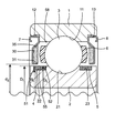
図1は、本発明の一実施形態の玉軸受の軸方向の半断面図である。 FIG. 1 is a half sectional view in the axial direction of a ball bearing according to an embodiment of the present invention.
図1に示すように、この玉軸受は、外輪1と、内輪2と、複数の玉3と、第1潤滑剤供給部材4と、第2潤滑剤供給部材5と、第1シールド板7と、第2シールド板8とを備える。
As shown in FIG. 1, the ball bearing includes an outer ring 1, an
上記外輪1は、その外輪1の内周面に、内周軌道溝11と、第1シールド板取付溝12と、第2シールド板取付溝13とを有している。上記第1シールド板取付溝12は、環状溝であって、外輪1の内周面の一端部に形成されている。また、上記第2シールド板取付溝13は、環状溝であって、外輪1の内周面の他端部に形成されている。上記内周軌道溝11は、第1シールド板取付溝12と、第2シールド板取付溝13の間に配置されている。
The outer ring 1 has an inner
一方、上記内輪2は、その内輪2の外周面に、外周軌道溝21と、第1環状溝22と、第2環状溝23とを有している。上記第1環状溝22は、内輪2の外周面の一端部に形成されている。また、上記第2環状溝23は内輪2の外周面の他端部に形成されている。上記外周軌道溝21は、第1環状溝22と、第2環状溝23の間に配置されている。
On the other hand, the
上記複数の玉3は、外輪1の内周軌道溝11と、内輪2の外周軌道溝21との間に、保持器6によって保持された状態で、周方向に所定の間隔を隔てられて配置されている。また、上記内周軌道溝11と、外周軌道溝21とは、深溝タイプの軌道溝となっている。上記第1および第2環状溝22,23の夫々は、軌道肩部の外周面に形成されている。この実施形態では、深溝玉軸受型の軌道溝11,21を採用して軌道肩部をより大きく形成し、その大きな軌道肩部を有効に利用している。上記第1および第2環状溝22,23の夫々は、輪状部材取付部を構成し、第1および第2環状溝22,23の夫々の二つの側面51,52(第2環状溝23の側面部には参照番号を付していない)は、輪状部材取付部の段部を構成している。
The plurality of
上記第1潤滑剤供給部材4は、環状であって、第1環状溝22に嵌入されて固定されている。上記第1潤滑剤供給部材4は、熱可塑性または熱硬化性樹脂(例えば、エラストマー、潤滑油、添加剤とを含む樹脂)や、二硫化モリブデン(MoS2)固体潤滑剤や、グラファイト(黒鉛)固体潤滑剤や、PTFE(商品名テフロン(登録商標))固体潤滑剤や、油溶性有機モリブデン化合物等の油分がしみ出る性質がある固体潤滑剤からなっている。上記第1潤滑剤供給部材4の軸方向の寸法は、第1環状溝22の軸方向の寸法と同一かまたは第1環状溝22の軸方向の寸法よりも若干小さい寸法になっている。上記第1潤滑剤供給部材4の軸方向の少なくとも一方の端面は、第1環状溝22の少なくとも一方の端面に当接している。上記第2潤滑剤供給部材5は、第2環状溝23に嵌入されている。
The first
また、上記第1シールド板7は、金属材料または樹脂材料からなっている。上記第1シールド板7は、外輪1と内輪2との間の軸方向の一方側の開口の大部分を塞いでいる。上記第1シールド板7の径方向外方の一端部は、第1シールド板取付溝12に嵌入固定されている。また、図1に示すように、上記第1潤滑剤供給部材4は、第1シールド板7の一部に径方向に重なる位置から保持器6に径方向に重なる位置まで軸方向に延在している。上記第1シールド板7の径方向の内方の他端部は、内輪2の外周面かまたは第1潤滑剤供給部材4に径方向に隙間を介して非接触に対向している。
The
上記第1シールド板7の上記他端部と、内輪2の外周面と、第1潤滑剤供給部材4の外周面とは、ラビリンスシールを構成している。すなわち、上記第1シールド板7の上記他端部の径方向の内方の端面と、内輪2の外周面との間には、玉軸受内の異物が通過することを妨げることが出来る位小さい径方向の寸法を有する一方、玉軸受内の異物が通過することを妨げることが出来る位大きな軸方向の寸法を有する隙間が形成されている。
The other end portion of the
詳しくは、図1に示すように、上記第1シールド板7は、その径方向の内方側の端部に、軸方向に延在する円筒部31を有している。このようにして、ラビリンスシールの軸方向の寸法を長くして、グリース35の流出の防止等のラビリンスシールの性能を向上するようにしている。この玉軸受は、非接触シールを採用することによりトルクを大きく低減している。
Specifically, as shown in FIG. 1, the
図1に示すように、上記第1シールド板7の軸方向の内方側の端面は、軸方向の内方側に開口する凹部30を有している。この凹部30には、玉軸受の始動時に、流動性を有する潤滑剤の一例としてのグリース35が封入されている。この玉軸受では、内輪2の外周面において第1環状溝22の軸方向の外周軌道溝21側とは反対側に位置する部分の最大の外径をDi[mm]とし、第1潤滑剤供給部材4の内径をdL[mm]とし、第1シールド板7の内径をdZ[mm]とし、第1潤滑剤供給部材4の径方向の弾性限界変形量をδL[mm]とし、第1潤滑剤供給部材4の外径をDL[mm]とするとき、Di<dL+δLになっていると共に、DL<dZになっている。
As shown in FIG. 1, the end face on the inner side in the axial direction of the
このようにして、上記第1潤滑剤供給部材4が、弾性変形によって、内輪2の軸方向の外端から第1環状溝22まで内輪2の外周面上を通過することができるようにし、第1潤滑剤供給部材4を、第1環状溝22に嵌入できるようにしている。
In this way, the first
また、この玉軸受では、上記内輪2の線膨張係数をk1[K−1]とし、第1潤滑剤供給部材4の線膨張係数をk2[K−1]とし、使用上限温度から室温を引いた温度をΔT[K]とするとき、Di+k1.ΔT.Di>dL+k2.ΔT.dLとなっている。このようにして、玉軸受の使用温度においては、内輪2と、第1潤滑剤供給部材4とが、温度変化により伸び縮みしても、第1潤滑剤供給部材4の内径が、内輪2の外周面において第1環状溝22の軸方向の外周軌道溝21側とは反対側に位置する部分の最大の外径を超えることがないようにしている。このようにして、第1潤滑剤供給部材4の軸方向の移動を規制して、第1潤滑剤供給部材4が、内輪2から離脱しないようにしている。
In this ball bearing, the linear expansion coefficient of the
尚、今までは、玉軸受の図1における左側の構造について主に説明したが、この玉軸受は、この玉軸受の軸方向を垂直に二等分する平面に対して面対称になっている。玉軸受の図1における右側の構造については、上述の左側の構造の説明をもって説明を省略する。 Until now, the structure of the left side of the ball bearing in FIG. 1 has been mainly described. However, this ball bearing is plane-symmetric with respect to a plane that bisects the axial direction of the ball bearing vertically. . The structure of the ball bearing on the right side in FIG. 1 will be omitted from the description of the structure on the left side described above.
上記実施形態によれば、環状の潤滑剤供給部材4,5が、外周面部55を有して内輪2の外周側に位置する輪状部材取付部に固定されているから、その潤滑剤供給部材4,5から軸方向に隣接する外周軌道溝21に潤滑油分を供給できて、さらに、外周軌道溝21から、玉3の転動面に潤滑油分を円滑に供給できる共に、その転動面を介して内周軌道溝11にも潤滑油分を円滑に供給できる。したがって、軌道溝11,21や上記転動面等からなる摺動部が焼付きにくいようにできると共に、玉配置室58内に封入するグリースの量も低減できて、攪拌抵抗を低減でき、低トルクを実現できる。
According to the above embodiment, the annular
また、上記実施形態によれば、輪状部材取付部が、内輪2の外周面に位置する環状溝22,23であるから、環状溝22,23の二つの側面51,52で、潤滑剤供給部材4,5の軸方向の一方側の移動および他方側の移動を規制でき、潤滑剤供給部材4,5の所望の位置から移動を防止できる。
Further, according to the above embodiment, since the annular member mounting portion is the
また、上記実施形態によれば、潤滑剤供給部材4,5が、保持器6に径方向に重なる部分を有しているから、潤滑剤供給部材4,5と、外周軌道溝21との距離が小さくなる。したがって、潤滑剤供給部材4,5から外周軌道溝21に円滑に潤滑油分を供給できる。
Further, according to the above embodiment, since the
また、上記実施形態によれば、潤滑剤供給部材4,5が、シールド板7,8に径方向に重なる部分を有しているから、潤滑剤供給部材4,5と、シールド板7,8の径方向の内方側の端部との間に油膜ができやすくなる。したがって、ラビリンスシールの密封性能を優れたものにできる。
Further, according to the above embodiment, since the
尚、上記実施形態では、潤滑剤供給部材4,5が、保持器6に径方向に重なる部分を有していたが、この発明では、潤滑剤供給部材は、保持器に径方向に重なる部分を有さなくても良い。
In the above embodiment, the
また、上記実施形態では、潤滑剤供給部材4,5が、シールド板7,8に径方向に重なる部分を有していたが、この発明では、潤滑剤供給部材は、シールド板に径方向に重なる部分を有さなくても良い。
Further, in the above embodiment, the
また、上記実施形態では、潤滑剤供給部材4,5は、環状部材であったが、この発明では、潤滑剤供給部材は、C字形状等、周方向の一箇所に切欠き部を有する形状であっても良い。潤滑剤供給部材は、輪状であれば良い。
In the above embodiment, the
また、上記実施形態では、Di+k1.ΔT.Di>dL+k2.ΔT.dLを満たしていたが、この発明では、Di+k1.ΔT.Di>dL+k2.ΔT.dLが、成立しなくても良い。 In the above embodiment, Di + k1. ΔT. Di> dL + k2. ΔT. dL was satisfied, but in the present invention, Di + k1. ΔT. Di> dL + k2. ΔT. dL may not be established.
また、上記実施形態では、玉配置室58にグリース35が封入されていたが、この発明では、玉配置室にグリース以外の流動性を有する潤滑剤が封入されても良く、例えば、玉配置室にグリースよりも粘度が低い潤滑油が封入されても良い。
In the above embodiment, the
また、上記実施形態では、図1に示すように、潤滑剤供給部材4,5の外周面と、内輪2の軌道肩部の外周面とが、面一となっていて、潤滑剤供給部材4,5の外周面と、内輪2の軌道肩部の外周面との夫々が、略同じ外径を有する円筒外周面の一部になっている。しかしながら、この発明では、潤滑剤供給部材の外周面と、内輪の軌道肩部の外周面とは、面一になっていなくても良く、潤滑剤供給部材の外周面の外径は、内輪の軌道肩部の外周面の外径よりも大きくても、同一でも、小さくてもいずれでも良い。尚、潤滑油分の円滑な軌道溝への供給という観点からは、潤滑剤供給部材の外周面の外径が、内輪の軌道肩部の外周面の外径よりも大きいか、または、同一である方が好ましい。
Moreover, in the said embodiment, as shown in FIG. 1, the outer peripheral surface of the
また、上記実施形態では、シールド板7,8が、軸方向の内方側に開口する凹部30を有して、その凹部30に始状態でグリース35が封入されていたが、この発明では、シールド板は、軸方向に開口する凹部を有さなくても良い。
Further, in the above embodiment, the
また、上記実施形態では、輪状部材取付部が、環状溝22,23であったが、この発明では、輪状部材取付部は、図2、すなわち、環状部材取付部の変形例を示す模式図に示すように、内輪102の外周軌道溝121の軌道肩部に形成されると共に、内輪102(外輪)の径方向に略延在する一つのみの段部151と、外周面部155とを有する構造であっても良い。そして、この輪状部材取付部に、輪状の潤滑剤供給部材105を、段部151に当接した状態で、外周面部155に締め代をもった状態で締まり嵌めするようにしても良い。
Moreover, in the said embodiment, although the annular member attachment part was the
1 外輪
2,102 内輪
3 玉
4 第1潤滑剤供給部材
5 第2潤滑剤供給部材
6 保持器
7 第1シールド板
8 第2シールド板
11 内周軌道溝
21,121 外周軌道溝
22 第1環状溝
23 第2環状溝
55,155 輪状部材取付部の外周面部
58 玉配置室
105 潤滑剤供給部材
151 輪状部材取付部の段部
DESCRIPTION OF SYMBOLS 1 Outer ring 2,102
Claims (2)
外周軌道溝を有すると共に、上記外輪の径方向に略延在する段部と、外周面部とを有する輪状部材取付部を有する内輪と、
上記外輪の内周軌道溝と、上記内輪の外周軌道溝との間に配置された玉と、
上記段部に当接している状態で上記輪状部材取付部に固定された輪状の潤滑剤供給部材と、
上記玉を保持する保持器と
を備え、
上記輪状部材取付部は、上記内輪の外周面に位置する環状溝であり、
上記潤滑剤供給部材は、上記環状溝に嵌入されて固定されており、
上記外輪に固定される一方、上記内輪の外周面に間隔をおいて位置し、かつ、上記潤滑剤供給部材に上記内輪の径方向に重なるシールド板を備え、
かつ、上記内輪の外周面において上記環状溝の軸方向の上記外周軌道溝側とは反対側に位置する部分の最大の外径をDi[mm]とし、上記潤滑剤供給部材の内径をdL[mm]とし、上記シールド板の内径をdZ[mm]とし、上記潤滑剤供給部材の径方向の弾性限界変形量をδL[mm]とし、上記潤滑剤供給部材の外径をDL[mm]とするとき、
Di<dL+δLであると共に、DL<dZであり、
上記内輪の線膨張係数をk1[K−1]とし、上記潤滑剤供給部材の線膨張係数をk2[K−1]とし、使用上限温度から室温を引いた温度をΔT[K]とするとき、
Di+k1.ΔT.Di>dL+k2.ΔT.dLであり、
上記潤滑剤供給部材は、上記シールド板の一部に上記径方向に重なる位置から上記保持器に上記径方向に重なる位置まで上記軸方向に延在していることを特徴とする玉軸受。 An outer ring having an inner circumferential raceway groove;
An inner ring having a ring-shaped member mounting portion having an outer circumferential raceway groove, a step portion extending substantially in the radial direction of the outer ring, and an outer peripheral surface portion;
A ball disposed between the inner raceway groove of the outer ring and the outer raceway groove of the inner ring;
A ring-shaped lubricant supply member fixed to the ring-shaped member mounting portion in a state of being in contact with the stepped portion ;
A cage for holding the ball ,
The ring-shaped member mounting portion is an annular groove located on the outer peripheral surface of the inner ring,
The lubricant supply member is fitted and fixed in the annular groove,
While being fixed to the outer ring, the outer ring surface of the inner ring is located at an interval, and the lubricant supply member includes a shield plate that overlaps in the radial direction of the inner ring,
In addition, the maximum outer diameter of the portion of the outer circumferential surface of the inner ring located on the opposite side to the outer circumferential raceway groove side in the axial direction of the annular groove is Di [mm], and the inner diameter of the lubricant supply member is dL [ mm], the inner diameter of the shield plate is dZ [mm], the elastic limit deformation in the radial direction of the lubricant supply member is δL [mm], and the outer diameter of the lubricant supply member is DL [mm]. and when,
Di <as well as a dL + δL, DL <dZ der is,
When the linear expansion coefficient of the inner ring is k1 [K-1], the linear expansion coefficient of the lubricant supply member is k2 [K-1], and the temperature obtained by subtracting the room temperature from the upper limit use temperature is ΔT [K]. ,
Di + k1. ΔT. Di> dL + k2. ΔT. dL,
The lubricant supply member, ball bearings, characterized that you have extend from a position overlapping the radial part to the axial direction to a position overlapping the radial direction to the cage of the shield plate.
上記潤滑剤供給部材は、環状部材であることを特徴とする玉軸受。 The ball bearing according to claim 1,
A ball bearing according to claim 1, wherein the lubricant supply member is an annular member .
Priority Applications (4)
| Application Number | Priority Date | Filing Date | Title |
|---|---|---|---|
| JP2012265531A JP5835199B2 (en) | 2012-12-04 | 2012-12-04 | Ball bearing |
| US14/087,742 US8870464B2 (en) | 2012-12-04 | 2013-11-22 | Ball bearing |
| EP13194199.9A EP2740958B1 (en) | 2012-12-04 | 2013-11-25 | Ball bearing |
| CN201310615940.7A CN103851072B (en) | 2012-12-04 | 2013-11-27 | Ball bearing |
Applications Claiming Priority (1)
| Application Number | Priority Date | Filing Date | Title |
|---|---|---|---|
| JP2012265531A JP5835199B2 (en) | 2012-12-04 | 2012-12-04 | Ball bearing |
Publications (3)
| Publication Number | Publication Date |
|---|---|
| JP2014109369A JP2014109369A (en) | 2014-06-12 |
| JP2014109369A5 JP2014109369A5 (en) | 2015-01-15 |
| JP5835199B2 true JP5835199B2 (en) | 2015-12-24 |
Family
ID=49709476
Family Applications (1)
| Application Number | Title | Priority Date | Filing Date |
|---|---|---|---|
| JP2012265531A Expired - Fee Related JP5835199B2 (en) | 2012-12-04 | 2012-12-04 | Ball bearing |
Country Status (4)
| Country | Link |
|---|---|
| US (1) | US8870464B2 (en) |
| EP (1) | EP2740958B1 (en) |
| JP (1) | JP5835199B2 (en) |
| CN (1) | CN103851072B (en) |
Families Citing this family (5)
| Publication number | Priority date | Publication date | Assignee | Title |
|---|---|---|---|---|
| JP6339433B2 (en) * | 2014-07-22 | 2018-06-06 | Ntn株式会社 | Ball bearing for spindle with built-in motor |
| US10415642B2 (en) * | 2015-06-09 | 2019-09-17 | Aktiebolaget Skf | Coupling system of a sealing assembly with a rotating annular element |
| CN108953387B (en) * | 2017-05-26 | 2021-10-15 | 舍弗勒技术股份两合公司 | Seal for a rolling bearing and rolling bearing |
| CN111486177A (en) * | 2019-01-28 | 2020-08-04 | 舍弗勒技术股份两合公司 | Dust cap and bearing |
| WO2023238242A1 (en) * | 2022-06-07 | 2023-12-14 | 株式会社ジェイテクト | Ball bearing |
Family Cites Families (21)
| Publication number | Priority date | Publication date | Assignee | Title |
|---|---|---|---|---|
| US2785023A (en) * | 1953-03-04 | 1957-03-12 | Daimler Benz Ag | Anti-friction bearings |
| US3144278A (en) * | 1960-12-09 | 1964-08-11 | Rothe Erde Eisenwerk | Bearing assembly |
| US3332728A (en) * | 1964-10-19 | 1967-07-25 | Raymond Corp | Hardened racewire ball bearing |
| US3675978A (en) * | 1970-11-12 | 1972-07-11 | Timken Co | Roller bearings |
| US3782795A (en) * | 1972-04-06 | 1974-01-01 | Timken Co | Tapered roller bearing |
| US4601592A (en) * | 1982-03-17 | 1986-07-22 | The Timken Company | Tapered roller bearing capable of sustained operation without lubricant replenishment |
| US4571097A (en) * | 1985-01-24 | 1986-02-18 | The Timken Company | Tapered roller bearing with pressurized rib ring |
| JPH0173521U (en) * | 1987-11-05 | 1989-05-18 | ||
| US5066145A (en) * | 1989-06-29 | 1991-11-19 | Tribology Systems, Inc. | Solid-lubricated bearing assembly |
| JPH11141557A (en) * | 1997-11-05 | 1999-05-25 | Nippon Seiko Kk | Rolling bearing |
| JP4051908B2 (en) | 2001-03-29 | 2008-02-27 | 日本精工株式会社 | Rolling bearing |
| JP2004084813A (en) * | 2002-08-27 | 2004-03-18 | Nsk Ltd | Rolling bearing |
| DE102005018616A1 (en) * | 2005-04-21 | 2006-10-26 | Schaeffler Kg | Angular contact ball bearing has annular grooves in inner and outer rings which act as lubricant storage system and are at least partly covered by ball bearings |
| DE502006008128D1 (en) * | 2006-03-22 | 2010-12-02 | Paul Mueller Gmbh & Co Kg | Bearings with a porous element to absorb lubricant |
| JP2008275037A (en) * | 2007-04-27 | 2008-11-13 | Nsk Ltd | Rolling bearing and swing arm |
| JP2009024796A (en) | 2007-07-20 | 2009-02-05 | Ntn Corp | Rolling bearing |
| JP2010019312A (en) | 2008-07-09 | 2010-01-28 | Jtekt Corp | Rolling bearing |
| JP2010156392A (en) * | 2008-12-26 | 2010-07-15 | Nsk Ltd | Rolling bearing |
| JP2012047269A (en) * | 2010-08-27 | 2012-03-08 | Ntn Corp | Ball bearing |
| US9528592B2 (en) * | 2012-06-26 | 2016-12-27 | Kinetech Power Company Llc | Solid-lubricated bearing assembly |
| CN202732686U (en) * | 2012-08-08 | 2013-02-13 | 福建省福安市新强轴承有限公司 | Deep groove ball bearing |
-
2012
- 2012-12-04 JP JP2012265531A patent/JP5835199B2/en not_active Expired - Fee Related
-
2013
- 2013-11-22 US US14/087,742 patent/US8870464B2/en not_active Expired - Fee Related
- 2013-11-25 EP EP13194199.9A patent/EP2740958B1/en not_active Not-in-force
- 2013-11-27 CN CN201310615940.7A patent/CN103851072B/en not_active Expired - Fee Related
Also Published As
| Publication number | Publication date |
|---|---|
| US20140153853A1 (en) | 2014-06-05 |
| EP2740958A1 (en) | 2014-06-11 |
| CN103851072B (en) | 2017-03-29 |
| EP2740958B1 (en) | 2017-06-21 |
| CN103851072A (en) | 2014-06-11 |
| US8870464B2 (en) | 2014-10-28 |
| JP2014109369A (en) | 2014-06-12 |
Similar Documents
| Publication | Publication Date | Title |
|---|---|---|
| JP5835199B2 (en) | Ball bearing | |
| JP5920443B2 (en) | Rolling bearing with seal ring | |
| WO2014192724A1 (en) | Anti-friction bearing | |
| US8641289B2 (en) | Triple-lip seals for bearings and bearings incorporating the same | |
| JP2014109369A5 (en) | ||
| JP2015086940A (en) | Rolling bearing | |
| US9926979B2 (en) | Sealing device for rolling bearing unit | |
| JP5866821B2 (en) | Roller bearing cage | |
| JP2008121820A (en) | Seal device for rolling bearing | |
| JP6981143B2 (en) | Ball bearing with seal | |
| JP2013047528A (en) | Cage for rolling bearing | |
| JP2013044346A (en) | Rolling bearing cage | |
| JP2012159114A (en) | Sealing structure for turning bearing | |
| CN105545961A (en) | Low-noise deep groove ball bearing | |
| JP6485014B2 (en) | Rolling bearing | |
| JP2018168871A (en) | Follower bearing | |
| JP2007170626A (en) | Sealing device for rolling bearing | |
| JP2009185980A (en) | Rolling bearing unit | |
| JP2008157370A (en) | Follower bearing | |
| JP2015218786A (en) | Angular contact ball bearing | |
| JP2023031532A (en) | Rolling bearing and rolling bearing device | |
| JP2005121194A (en) | Polymer lubricant-sealed bearing | |
| JP6384106B2 (en) | Roller bearing cage | |
| JP2020045948A (en) | Rolling bearing | |
| JP2006234081A (en) | Sealed rolling bearing |
Legal Events
| Date | Code | Title | Description |
|---|---|---|---|
| A521 | Request for written amendment filed |
Free format text: JAPANESE INTERMEDIATE CODE: A523 Effective date: 20141119 |
|
| A621 | Written request for application examination |
Free format text: JAPANESE INTERMEDIATE CODE: A621 Effective date: 20141119 |
|
| A977 | Report on retrieval |
Free format text: JAPANESE INTERMEDIATE CODE: A971007 Effective date: 20150206 |
|
| A131 | Notification of reasons for refusal |
Free format text: JAPANESE INTERMEDIATE CODE: A131 Effective date: 20150217 |
|
| A521 | Request for written amendment filed |
Free format text: JAPANESE INTERMEDIATE CODE: A523 Effective date: 20150420 |
|
| RD04 | Notification of resignation of power of attorney |
Free format text: JAPANESE INTERMEDIATE CODE: A7424 Effective date: 20150630 |
|
| TRDD | Decision of grant or rejection written | ||
| A01 | Written decision to grant a patent or to grant a registration (utility model) |
Free format text: JAPANESE INTERMEDIATE CODE: A01 Effective date: 20151006 |
|
| A61 | First payment of annual fees (during grant procedure) |
Free format text: JAPANESE INTERMEDIATE CODE: A61 Effective date: 20151019 |
|
| R150 | Certificate of patent or registration of utility model |
Ref document number: 5835199 Country of ref document: JP Free format text: JAPANESE INTERMEDIATE CODE: R150 |
|
| LAPS | Cancellation because of no payment of annual fees |