JP2014006291A - Microscope, microscope system and image synthesis method - Google Patents
Microscope, microscope system and image synthesis method Download PDFInfo
- Publication number
- JP2014006291A JP2014006291A JP2012139796A JP2012139796A JP2014006291A JP 2014006291 A JP2014006291 A JP 2014006291A JP 2012139796 A JP2012139796 A JP 2012139796A JP 2012139796 A JP2012139796 A JP 2012139796A JP 2014006291 A JP2014006291 A JP 2014006291A
- Authority
- JP
- Japan
- Prior art keywords
- microscope
- microscope objective
- image
- objective lenses
- imaging
- Prior art date
- Legal status (The legal status is an assumption and is not a legal conclusion. Google has not performed a legal analysis and makes no representation as to the accuracy of the status listed.)
- Granted
Links
- 238000001308 synthesis method Methods 0.000 title 1
- 238000003384 imaging method Methods 0.000 claims abstract description 131
- 230000003287 optical effect Effects 0.000 claims abstract description 29
- 230000009467 reduction Effects 0.000 claims abstract description 6
- 238000000034 method Methods 0.000 claims description 18
- 239000002131 composite material Substances 0.000 claims description 15
- 230000007246 mechanism Effects 0.000 claims description 12
- 239000000203 mixture Substances 0.000 claims description 9
- 238000010586 diagram Methods 0.000 description 22
- 230000005499 meniscus Effects 0.000 description 16
- 230000004075 alteration Effects 0.000 description 12
- 230000008569 process Effects 0.000 description 6
- 230000015572 biosynthetic process Effects 0.000 description 5
- 230000000694 effects Effects 0.000 description 5
- 238000005286 illumination Methods 0.000 description 5
- 238000003786 synthesis reaction Methods 0.000 description 5
- 238000000605 extraction Methods 0.000 description 4
- 239000000284 extract Substances 0.000 description 3
- 201000009310 astigmatism Diseases 0.000 description 2
- 239000006059 cover glass Substances 0.000 description 2
- 230000002093 peripheral effect Effects 0.000 description 2
- 206010010071 Coma Diseases 0.000 description 1
- 230000009471 action Effects 0.000 description 1
- 230000006870 function Effects 0.000 description 1
- 238000004519 manufacturing process Methods 0.000 description 1
- 230000015654 memory Effects 0.000 description 1
- 239000007787 solid Substances 0.000 description 1
- 230000002194 synthesizing effect Effects 0.000 description 1
Images


Landscapes
- Microscoopes, Condenser (AREA)
- Lenses (AREA)
Abstract
Description
本発明は、顕微鏡、顕微鏡システム及び画像合成方法に関するものである。 The present invention relates to a microscope, a microscope system, and an image composition method.
従来、標本の複数個所を同時に撮像可能な顕微鏡として、少なくとも2つの顕微鏡対物レンズを備えた顕微鏡がある(特許文献1)。特許文献1に開示された顕微鏡では、2つの顕微鏡対物レンズが所定の間隔で配置されている。
2. Description of the Related Art Conventionally, there is a microscope provided with at least two microscope objective lenses as a microscope capable of simultaneously imaging a plurality of locations of a specimen (Patent Document 1). In the microscope disclosed in
特許文献1に開示された顕微鏡では、2つの顕微鏡対物レンズの間隔は、ウェルのピッチの整数倍となっている。この場合、2つの顕微鏡対物レンズの間にあるウェルを撮像するためには、ウェルプレートと顕微鏡対物レンズとを相対的に移動させなくてはならない。そのため、撮像に時間がかかるという問題が生じる。
In the microscope disclosed in
本発明は、上記に鑑みてなされたものであって、標本上の広い範囲を、短い時間で撮像できる顕微鏡、顕微鏡システム及び画像合成方法を提供することを目的とする。 The present invention has been made in view of the above, and an object of the present invention is to provide a microscope, a microscope system, and an image composition method that can image a wide range on a specimen in a short time.
上述した課題を解決し、目的を達成するために、本発明に係る顕微鏡は、複数の顕微鏡対物レンズと、撮像素子と、を有する顕微鏡であって、複数の顕微鏡対物レンズの各々は、所定の広さの標本側撮像範囲を有し、隣り合う顕微鏡対物レンズは、標本側撮像範囲の一部が重なるように配置されていることを特徴とする。 In order to solve the above-described problems and achieve the object, a microscope according to the present invention is a microscope having a plurality of microscope objective lenses and an imaging device, and each of the plurality of microscope objective lenses is a predetermined one. The microscope-side objective lens having a wide specimen-side imaging range is arranged so that a part of the specimen-side imaging range overlaps.
また、本発明に係る顕微鏡システムは、顕微鏡と、画像処理装置と、を有し、画像処理装置は、複数の顕微鏡対物レンズの各々から得られた画像を合成することを特徴とする。 A microscope system according to the present invention includes a microscope and an image processing device, and the image processing device synthesizes images obtained from each of a plurality of microscope objective lenses.
また、本発明に係る画像合成方法は、所定の広さの標本側撮像範囲を複数設定し、複数の標本側撮像範囲を同時に撮像する撮像ステップと、撮像ステップで得られた複数の画像を使って、合成画像を生成する画像生成ステップを有し、撮像ステップにおいて、標本側撮像範囲の一部が重なるように撮像を行い、画像生成ステップは、複数の画像から重複画像を抽出し、重複画像から、複数の画像の合成位置を決定し、合成位置の情報に基づいて、合成画像を生成することを特徴とする。 In addition, the image composition method according to the present invention sets a plurality of specimen-side imaging ranges having a predetermined width, uses an imaging step for simultaneously imaging a plurality of specimen-side imaging ranges, and a plurality of images obtained in the imaging step. An image generation step for generating a composite image, and in the imaging step, imaging is performed so that a part of the specimen-side imaging range overlaps, and the image generation step extracts duplicate images from a plurality of images, Then, a composite position of a plurality of images is determined, and a composite image is generated based on the composite position information.
本発明は、標本上の広い範囲を、短い時間で撮像できる顕微鏡、顕微鏡システム及び画像合成方法を提供できるという効果を奏する。 The present invention has an effect of providing a microscope, a microscope system, and an image composition method that can image a wide range on a specimen in a short time.
以下に、本発明に係る顕微鏡、顕微鏡システム及び画像合成方法の実施形態を、図面に基づいて詳細に説明する。なお、この実施形態によりこの発明が限定されるものではない。 Hereinafter, embodiments of a microscope, a microscope system, and an image composition method according to the present invention will be described in detail with reference to the drawings. In addition, this invention is not limited by this embodiment.
本実施形態の顕微鏡は、複数の顕微鏡対物レンズと、撮像素子と、を有する顕微鏡であって、複数の顕微鏡対物レンズの各々は、所定の広さの標本側撮像範囲を有し、隣り合う顕微鏡対物レンズは、標本側撮像範囲の一部が重なるように配置されていることを特徴とする。 The microscope of the present embodiment is a microscope having a plurality of microscope objective lenses and an image sensor, and each of the plurality of microscope objective lenses has a specimen-side imaging range having a predetermined width, and is an adjacent microscope. The objective lens is arranged so that a part of the specimen-side imaging range is overlapped.
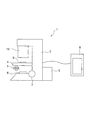
図1は、本実施形態の顕微鏡の構成を示す模式図である。図1に示すように、顕微鏡1は、顕微鏡本体2と、光源3と、ステージ4と、XYハンドル5と、コンデンサレンズ6と、照準機構7と、顕微鏡対物レンズユニット10と、を有する。
FIG. 1 is a schematic diagram showing the configuration of the microscope of the present embodiment. As shown in FIG. 1, the
顕微鏡本体2には、光源3とコンデンサレンズ6が取り付けられている。光源3からの照明光は、コンデンサレンズ6に入射する。また、顕微鏡本体2には、ステージ4が配置されている。このステージ4に標本Sが載置されている。光源3からの照明光は、コンデンサレンズ6を介して、標本Sに照射される。
A
また、ステージ4を挟んで、コンデンサレンズ6と対向する位置に、顕微鏡対物レンズユニット10が配置されている。後述するように、顕微鏡対物レンズユニット10は複数の顕微鏡対物レンズを有している。この顕微鏡対物レンズユニット10は、顕微鏡本体2に取り付けられている。よって、標本Sの像は、顕微鏡対物レンズユニット10によって撮像される。なお、顕微鏡1は表示装置8を備えていても良い。このようにすることで、撮像された標本Sの像は、表示装置8に表示されるので、観察者は標本Sの画像を表示装置8で見ることができる。
A microscope
なお、ステージ4は、コンデンサレンズ6(あるいは、顕微鏡対物レンズユニット10)の光軸と直交する面内で、XY方向に移動可能になっている。XYハンドル5を操作することで、ステージ4をXY方向へ移動させることができる。また、顕微鏡本体2には、照準機構7が設けられている。この照準機構7を操作することで、ステージ4を上下方向に移動させることができる。これにより、標本Sに対する合焦が行なえる。また、図2に示す顕微鏡1’のように、レボルバ9を設けても良い。
Note that the
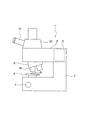
図2は、本実施形態の別の顕微鏡の構成を示す模式図である。なお、図1と同じ構成については同じ番号を付し、説明は省略する。 FIG. 2 is a schematic diagram showing the configuration of another microscope of the present embodiment. In addition, the same number is attached | subjected about the same structure as FIG. 1, and description is abbreviate | omitted.
図2に示すように、顕微鏡1’は、顕微鏡本体2と、光源3と、投光管3’と、ステージ4と、照準機構7と、レボルバ9と、顕微鏡対物レンズユニット10と、を有する。
As shown in FIG. 2, the
顕微鏡本体2の上部には、投光管3’の一端が取り付けられている。投光管3’には、光源3が設けられている。また、顕微鏡本体2には、投光管3’の他端と対向する位置に、ステージ4が配置されている。このステージ4に標本Sが載置されている。また、顕微鏡本体2には、照準機構7が設けられている。この照準機構7を操作することで、ステージ4を上下方向に移動させることができる。これにより、標本Sに対する合焦が行なえる。また、顕微鏡1と同様に、ステージ4をXY方向へ移動させるようにしても良い。
One end of a
投光管3’の他端側の底部には、レボルバ9が取り付けられている。そして、このレボルバ9に、顕微鏡対物レンズユニット10や他の顕微鏡対物レンズが取り付けられている。レボルバ9を回転させることで、顕微鏡対物レンズユニット10や他の顕微鏡対物レンズを、標本S上に位置させることができる。
A
顕微鏡対物レンズユニット10を標本S上に位置させることで、標本Sの像が、顕微鏡対物レンズユニット10によって撮像される。なお、顕微鏡1’は、顕微鏡1と同様に表示装置8を備えていても良い。このようにすることで、撮像された標本Sの像は、表示装置8に表示されるので、観察者は標本Sの画像を表示装置8で見ることができる。
By positioning the microscope
なお、顕微鏡1’では、投光管3’の他端側の上部に、鏡筒30を取り付けることができる。そして、この鏡筒30に、双眼部31を取り付けることができる。双眼部31を取り付けた状態で、顕微鏡対物レンズを標本S上に位置させることで、観察者は標本Sの光学像を肉眼で観察することができる。
In the
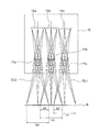
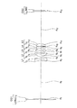
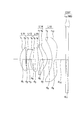
図3は、顕微鏡対物レンズユニットの構成を示す図である。顕微鏡対物レンズユニット10は、複数の顕微鏡対物レンズ、すなわち、顕微鏡対物レンズ11a、11b、11cを備える。顕微鏡対物レンズ11a、11b、11cの各々は、標本Sに対向して配置されている。また、図3では、顕微鏡対物レンズ11a、11b、11cの各々は、等間隔で一列に配置されている。なお、顕微鏡対物レンズ11a、11b、11cの各々には、後述の第1の顕微鏡対物レンズが用いられている。また、図3では、顕微鏡対物レンズの数は3であるが、2であっても良く、また、4以上であっても良い。
FIG. 3 is a diagram illustrating a configuration of the microscope objective lens unit. The microscope
顕微鏡対物レンズ11a、11b、11cの各々は、所定の広さの標本側撮像範囲La、Lb、Lc(以下、単に、撮像範囲La、Lb、Lc、とする)を有する。ここで、顕微鏡対物レンズ11aと11bは隣り合っている。そして、顕微鏡対物レンズ11aと11bは、撮像範囲Laと撮像範囲Lbの一部が重なるように配置されている。同様に、顕微鏡対物レンズ11bと11cは隣り合っており、しかも、撮像範囲Lbと撮像範囲Lcの一部が重なるように配置されている。
Each of the
顕微鏡対物レンズ11aの像位置には、撮像素子12aが配置されている。同様に、顕微鏡対物レンズ11bの像位置には、撮像素子12bが配置され、顕微鏡対物レンズ11cの像位置には、撮像素子12cが配置されている。そして、撮像素子12a、12b、12cの各々も、等間隔で一列に配置されている。
An
ここで、図3に示すように、撮像範囲Laと撮像範囲Lbには、重複領域X1が存在する。また、撮像範囲Lbと撮像範囲Lcには、重複領域X2が存在する。そのため、重複領域X1の像は、撮像素子12aと12bで撮影され、重複領域X2の像は、撮像素子12bと12cによって撮像される。
Here, as shown in FIG. 3, an overlapping region X1 exists in the imaging range La and the imaging range Lb. In addition, an overlapping region X2 exists in the imaging range Lb and the imaging range Lc. Therefore, the image of the overlapping region X1 is captured by the
このように、本実施形態の顕微鏡では、2つの撮像範囲の一部が重複するので、一方の撮像範囲と他方の撮像範囲の間に、隙間(撮像していない領域)が生じない。そのため、標本上の広い範囲を一度に撮影できる。その結果、本実施形態の顕微鏡によれば、標本S上の広い範囲の撮像(画像の取得)に時間がかからない。 As described above, in the microscope of this embodiment, a part of the two imaging ranges overlaps, so that no gap (an area where no imaging is performed) occurs between one imaging range and the other imaging range. Therefore, a wide range on the specimen can be photographed at once. As a result, according to the microscope of the present embodiment, it does not take time to capture a wide range on the specimen S (image acquisition).
また、図3に示すように、本実施形態の顕微鏡では、撮像範囲(La、Lb、Lc)は顕微鏡対物レンズ(11a、11b、11c)の外径よりも大きい(広い)。そのため、上記のように、隣り合う顕微鏡対物レンズを近づけることで、重複領域(X1、X2)を生じさせることができる。また、隣り合う顕微鏡対物レンズの間隔を変化させることで、重複領域の面積を変化させることができる。 As shown in FIG. 3, in the microscope of the present embodiment, the imaging range (La, Lb, Lc) is larger (wider) than the outer diameter of the microscope objective lens (11a, 11b, 11c). Therefore, as described above, overlapping regions (X1, X2) can be generated by bringing adjacent microscope objective lenses closer to each other. In addition, the area of the overlapping region can be changed by changing the interval between adjacent microscope objective lenses.
図4は、光軸と直交する面内で標本側撮像範囲を見た図である。図4において、円は顕微鏡対物レンズの実視野、すなわち、顕微鏡対物レンズが像を形成できる標本S側での範囲である。また、四角は標本側撮像範囲、すなわち、顕微鏡対物レンズによって投影された撮像素子の撮像面の範囲である。ここで、破線は、顕微鏡対物レンズ11aにおける実視野と標本側撮像範囲を示している。また、実線は、顕微鏡対物レンズ11bにおける実視野と標本側撮像範囲を示している。また、2点鎖線は、顕微鏡対物レンズ11cにおける実視野と標本側撮像範囲を示している。
FIG. 4 is a view of the specimen-side imaging range in a plane orthogonal to the optical axis. In FIG. 4, the circle is a real field of the microscope objective lens, that is, a range on the specimen S side where the microscope objective lens can form an image. Further, the square is the specimen-side imaging range, that is, the range of the imaging surface of the imaging device projected by the microscope objective lens. Here, the broken lines indicate the real field of view and the specimen-side imaging range in the microscope
図4に示すように、顕微鏡対物レンズ11a、11b、11cの各々は、隣り合う顕微鏡対物レンズの実視野が重なるように配置されるだけではなく、標本側撮像範囲(投影された撮像素子の撮像面)が重なるように配置されている。
As shown in FIG. 4, each of the
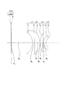
図5は、別の顕微鏡対物レンズユニットの構成を示す模式図である。顕微鏡対物レンズユニット13は、複数の顕微鏡対物レンズ14a、14b、14cと、複数の結像レンズ15a、15b、15cを備える。顕微鏡対物レンズ14a、14b、14cの各々は、標本Sに対向して配置されている。結像レンズ15a、15b、15cの各々は、撮像素子16a、16b、16cの各々に対向して配置されている。
FIG. 5 is a schematic diagram showing a configuration of another microscope objective lens unit. The microscope
顕微鏡対物レンズ14aからは平行光束が出射する。この平行光束は、結像レンズ15aに入射し、所定の位置に集光する。このように、顕微鏡対物レンズ14aと結像レンズ15aとの間は、アフォーカルになっている。顕微鏡対物レンズ14bと結像レンズ15bとの間、顕微鏡対物レンズ14cと結像レンズ15cとの間も、アフォーカルになっている。
A parallel light beam is emitted from the microscope
結像レンズ15aによる集光位置には標本Sの像が形成されるので、この集光位置に撮像素子16aが配置される。同様に、結像レンズ15bによる集光位置に撮像素子16bが配置され、結像レンズ15cによる集光位置に撮像素子16cが配置されている。
Since an image of the sample S is formed at the condensing position by the
また、顕微鏡対物レンズ14a、14b、14cの各々は、等間隔で一列に配置されている。同様に、結像レンズ15a、15b、15cの各々も、等間隔で一列に配置されている。なお、顕微鏡対物レンズ14a、14b、14cの各々には、後述の第2の顕微鏡対物レンズが用いられている。また、結像レンズ15a、15b、15cの各々には、後述の結像レンズが用いられている。
Further, each of the
なお、図示は省略するが、顕微鏡対物レンズ14a、14b、14cの各々も、撮像範囲(所定の広さの標本側撮像範囲)を有する。そして、顕微鏡対物レンズ14aと14b、顕微鏡対物レンズ14bと14cは、撮像範囲の一部が重なるように配置されている。なお、顕微鏡対物レンズユニット13の技術的意義(作用効果)は顕微鏡対物レンズユニット10と同じなので、詳細な説明は省略する。
Although not shown, each of the
また、顕微鏡対物レンズユニット10、13において、隣り合う撮像素子の間に遮光板を配置しても良い。顕微鏡対物レンズユニット10を用いて説明すると、図6に示すように、遮光板18が顕微鏡対物レンズ11aと顕微鏡対物レンズ11bとの間、顕微鏡対物レンズ11bと顕微鏡対物レンズ11cとの間に設けられている。そして、遮光板18の一端は対物レンズの近傍にあり、遮光板18の他端は撮像素子12a、12b、12cの近傍にある。
Further, in the microscope
この顕微鏡対物レンズ11aと顕微鏡対物レンズ11bの間に配置された遮光板18によって、顕微鏡対物レンズ11aからの光が隣接する撮像素子12bに結像されること(入射すること)、および顕微鏡対物レンズ11bからの光が隣接する撮像素子12aに結像されることを確実に制限することができる。このようにすることで、隣接する顕微鏡対物レンズにより結像される像が混ざり合うクロストークの発生を低減することができる。なお、顕微鏡対物レンズユニット13において、遮光板18を用いるようにしても良い。
The light from the microscope
また、顕微鏡対物レンズユニット10、13では、3つの撮像素子を用いたが、1つの撮像素子を用いても良い。
In the microscope
また、本実施形態の顕微鏡では、複数の顕微鏡対物レンズの各々は、縮小光学系であることが好ましい。 In the microscope of this embodiment, each of the plurality of microscope objective lenses is preferably a reduction optical system.
図3に示すように、撮像範囲Laの広さは、撮像素子12aの撮像面の広さよりも広い。同様に、撮像範囲Lbの広さは、撮像素子12bの撮像面の広さよりも広く、撮像範囲Lcの広さは、撮像素子12cの撮像面の広さよりも広い。このように、本実施形態の顕微鏡では、顕微鏡対物レンズによって、広い面積の撮像範囲が、狭い面積の撮像面に縮小投影されていることになる。これは、顕微鏡対物レンズ11a、11b、11cの各々が、縮小光学系であることを示している。
As shown in FIG. 3, the width of the imaging range La is wider than the width of the imaging surface of the
このように、顕微鏡対物レンズ11a、11b、11cの各々を縮小光学系にすることで、標本S側で撮像範囲に重複領域が生じているにもかかわらず、撮像素子側では、顕微鏡対物レンズ11a、11b、11cの各々で形成された像を、空間的に分離させることができる。よって、空間的に分離された各々の像を、撮像素子12a、12b、12cの各々で撮像することができる。
As described above, by making each of the
なお、顕微鏡対物レンズ11a、11b、11cの各々が拡大光学系の場合、重複領域がゼロの状態(撮像範囲La、Lb、Lcの各々が隣接している状態)であっても、顕微鏡対物レンズ11aで形成された像の一部と、顕微鏡対物レンズ11bで形成された像の一部とが、像面で重なり合う。また、顕微鏡対物レンズ11bで形成された像の一部と、顕微鏡対物レンズ11cで形成された像の一部とが、像面で重なり合う。
Note that when each of the
このように、顕微鏡対物レンズが拡大光学系の場合、重複領域がゼロの状態であっても、顕微鏡対物レンズ11a、11b、11cの各々で形成された像を、空間的に分離させることができない。そのため、顕微鏡対物レンズが拡大光学系の場合は、重複領域を設けることができない。
Thus, when the microscope objective lens is a magnifying optical system, the images formed by each of the
また、顕微鏡対物レンズ11a、11b、11cの各々が等倍光学系の場合、重複領域がゼロの状態では、隣り合う像で重なり合いは生じない。しかしながら、重複領域を設けようとして、隣り合う対物レンズの間隔を狭くすると、隣り合う像で重なり合いが生じてしまう。そのため、顕微鏡対物レンズが等倍光学系の場合は、重複領域を設けることができない。
Further, when each of the
なお、顕微鏡対物レンズ14a、14b、14cの各々も、縮小光学系となっている。よって、顕微鏡対物レンズ11a、11b、11cと同様の作用効果を生じる。
Note that each of the
また、本実施形態の顕微鏡では、複数の顕微鏡対物レンズの各々は、標本側が非テレセントリックな光学系であることが好ましい。 Moreover, in the microscope of this embodiment, it is preferable that each of the plurality of microscope objective lenses is a non-telecentric optical system on the specimen side.
図3に示すように、軸外主光線CL1、CL2は、標本Sの面の法線と平行になっていない。これは、顕微鏡対物レンズ11a、11b、11cの各々が、標本側において非テレセントリックな光学系になっているからである。
As shown in FIG. 3, the off-axis chief rays CL1 and CL2 are not parallel to the normal of the surface of the sample S. This is because each of the
このように、顕微鏡対物レンズ11a、11b、11cの各々を、標本側が非テレセントリックな光学系にすることで、撮像範囲を顕微鏡対物レンズの外形(直径)よりも広くすることができる。そのため、隣り合う撮像範囲で重複領域を生じさせることができる。
Thus, by making each of the
なお、顕微鏡対物レンズ14a、14b、14cの各々も、標本側が非テレセントリックな光学系となっている。よって、顕微鏡対物レンズ11a、11b、11cと同様の作用効果を生じる。
Each of the
また、本実施形態の顕微鏡では、複数の顕微鏡対物レンズの各々は、最も標本側のレンズが負屈折力を有することが好ましい。 In the microscope according to the present embodiment, it is preferable that each of the plurality of microscope objective lenses has a negative refractive power at the most specimen side.
このようにすることで、顕微鏡対物レンズ11a、11b、11cの各々において、標本Sに向かう軸外主光線CL1、CL2を発散する方向に広げる(光軸から離れる方向に向かわせる)ことができる。これにより、撮像範囲を、顕微鏡対物レンズの外径(直径)よりも広くすることができる。そのため、隣り合う撮像範囲で重複領域を生じさせることができる。
By doing in this way, in each of the
なお、顕微鏡対物レンズ14a、14b、14cの各々も、最も標本S側のレンズが負屈折力を有する。よって、顕微鏡対物レンズ11a、11b、11cと同様の作用効果を生じる。
In each of the
また、本実施形態の顕微鏡では、複数の顕微鏡対物レンズの各々は、以下の条件式(1)を満足することが好ましい。
Dmm<A<3Dmm (1)
ここで、
Aは、標本側撮像範囲の直径、
Dは、最も標本側のレンズの外形の直径、
である。
In the microscope of this embodiment, it is preferable that each of the plurality of microscope objective lenses satisfies the following conditional expression (1).
Dmm <A <3Dmm (1)
here,
A is the diameter of the sample-side imaging range,
D is the outer diameter of the lens on the most specimen side,
It is.
図3に示した顕微鏡対物レンズユニット10では、レンズデータは後述するが、A=6mm、D=3mm、図5に示した顕微鏡対物レンズユニットでは、A=11.3mm、D=7.5mmであることからいずれも条件式(1)を満足する。
In the microscope
顕微鏡対物レンズ11a、11b、11c、14a、14b、14cの各々が、条件式(1)を満足することで、適切な重複領域を生じさせた上で、周辺減光の少ない画像を得ることができる。なお、標本側撮像範囲が矩形の場合は、Aは辺の長さ(長辺あるいは短辺)である。
Each of the
条件式(1)の下限値を下回ると、隣り合う撮像範囲において重複領域を生じさせることができない。条件式(1)の上限値を上回ると、軸上光束の径に比べて、軸外光束の径が小さく(細く)なり過ぎるので、周辺減光が大きくなる。また、レンズを通過する光線の角度が大きくなるため、フレアの発生する可能性が高くなる。 If the lower limit value of conditional expression (1) is not reached, an overlapping area cannot be generated in adjacent imaging ranges. If the upper limit value of conditional expression (1) is exceeded, the diameter of the off-axis light beam becomes too small (thinner) compared to the diameter of the on-axis light beam, so that the peripheral attenuation becomes large. In addition, since the angle of the light beam passing through the lens increases, the possibility of occurrence of flare increases.
また、本実施形態の顕微鏡では、複数の顕微鏡対物レンズの各々は、倍率が同じ顕微鏡対物レンズであることが好ましい。 In the microscope according to the present embodiment, each of the plurality of microscope objective lenses is preferably a microscope objective lens having the same magnification.
顕微鏡対物レンズ11a、11b、11cの各々を、同じ倍率の顕微鏡対物レンズにすることで、同じ倍率の画像が得られるので、観察が容易となる。また、後述の画像処理(画像合成)を行なう場合、画像処理が容易になる。
By making each of the
なお、顕微鏡対物レンズ14a、14b、14cの各々も、倍率が同じ顕微鏡対物レンズにするのが好ましい。
Note that each of the
また、本実施形態の顕微鏡では、複数の顕微鏡対物レンズの各々は、隣り合う顕微鏡対物レンズの間隔が最小となるように配列されていることが好ましい。 Moreover, in the microscope of this embodiment, it is preferable that each of the plurality of microscope objective lenses is arranged so that the interval between adjacent microscope objective lenses is minimized.
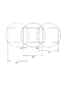
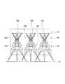
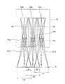
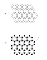
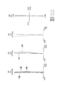
このようにすることで、隣り合う撮像範囲を効率よく重複させることができる。図7は顕微鏡対物レンズの配置を示す図であって、(a)は密になる配列を示す図、(b)は、密になる配列で照明用の光源を配置した図である。顕微鏡対物レンズの各々を保持する保持枠が円筒の場合、図7(a)に示すように、1つの顕微鏡対物レンズに対して、6つの顕微鏡対物レンズが接するように、各々の顕微鏡対物レンズを配置するのが良い。 By doing in this way, adjacent imaging ranges can be efficiently overlapped. 7A and 7B are diagrams showing the arrangement of microscope objective lenses, where FIG. 7A is a diagram showing a dense arrangement, and FIG. 7B is a diagram in which illumination light sources are arranged in a dense arrangement. When the holding frame for holding each of the microscope objective lenses is a cylinder, as shown in FIG. 7A, each microscope objective lens is attached so that six microscope objective lenses are in contact with one microscope objective lens. It is good to arrange.
なお、図7(a)において、実線の円は顕微鏡対物レンズ(保持枠)を示し、破線の円は顕微鏡対物レンズの実視野を示している。また、撮像範囲(標本側撮像範囲)は示していないが、撮像範囲は重複するようになっている。 In FIG. 7A, a solid circle indicates a microscope objective lens (holding frame), and a broken circle indicates a real field of view of the microscope objective lens. Further, although the imaging range (sample-side imaging range) is not shown, the imaging ranges are overlapped.
また、図7(b)に示すように、隣り合う顕微鏡対物レンズの間に、照明用の光源17を配置しても良い。なお、図7(b)では、1つの顕微鏡対物レンズの周囲に6つの光源17を配置しているが、光源の数はこれに限られない。また、顕微鏡対物レンズユニット10、13(図3、図5)においても、隣り合う顕微鏡対物レンズの間に、光源17を配置することができる。
Further, as shown in FIG. 7B, an
また、顕微鏡対物レンズは、Fナンバの小さな顕微鏡対物レンズを用いるのが良い。また、上述の説明では、明視野法での撮像について説明したが、位相差法や微分干渉法を用いた撮像を行なっても良い。 As the microscope objective lens, a microscope objective lens having a small F number is preferably used. In the above description, imaging using the bright field method has been described. However, imaging using a phase difference method or a differential interference method may be performed.
また、本実施形態の顕微鏡システムは、上述の顕微鏡と、画像処理装置と、を有し、画像処理装置は、複数の顕微鏡対物レンズの各々から得られた画像を合成することを特徴とする。 The microscope system of the present embodiment includes the above-described microscope and an image processing device, and the image processing device synthesizes images obtained from each of a plurality of microscope objective lenses.
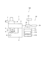
図8は、本実施形態の顕微鏡システムの構成を示す模式図である。図8に示すように、顕微鏡システム100は、顕微鏡1’と、画像処理装置20と有する。なお、顕微鏡1’については既に説明をしたので、説明を省略する。なお、顕微鏡1’に代えて、顕微鏡1を用いても良い。
FIG. 8 is a schematic diagram showing the configuration of the microscope system of the present embodiment. As shown in FIG. 8, the
画像処理装置20では、複数の顕微鏡対物レンズの各々から得られた画像を合成する。この画像処理装置20は、画像処理部21と、制御部22と、表示部23と、記憶部24と、を備える。また、画像処理部21は、重複画像抽出部211と、観察画像合成部213と、を有する。また、重複画像抽出部211は、合成位置決定部212を有する。
The
画像処理装置20は、ワークステーションやパソコン等の汎用コンピュータで実現される。上記のように、顕微鏡1’では、複数の像が撮像される。撮像された像の画像データ(デジタルデータ)は、制御部22を介して、画像処理装置20に送られる。画像処理装置20は、複数の画像データを画像処理し、1つの観察画像に合成して表示部23に表示する。制御部22は、画像処理部21、表示部23及び記憶部24に対して、動作タイミングの指示やデータの転送等を行い、各部の動作を統括的に制御する。また、制御部22は、顕微鏡1とのデータ転送等を行なう。
The
表示部23は、LCDやLEDの表示装置によって実現される。表示部23は、制御部22から入力される表示信号に基づいて、撮像で得た各々の画像や、合成画像や、制御用の画面等を表示する。
The
記憶部24は、各種ICメモリ、ハードディスク、CD−ROM等の情報記憶媒体及びその読取装置等によって実現される。記憶部24は、画像処理装置20の動作に係るプログラムや、画像処理装置20の備える種々の機能を実現するためのプログラム、これらプログラムの実行に係るデータ等が格納される。
The
画像処理部21は、制御部22を介して、顕微鏡1から複数の画像データを取得し、複数の画像データから1つの合成画像を生成する。例えば、顕微鏡対物レンズユニット10で標本Sの像を撮像すると、顕微鏡対物レンズ11aを介して取得した画像Iaと、顕微鏡対物レンズ11bを介して取得した画像Ibと、顕微鏡対物レンズ11cを介して取得した画像Icと、が得られる。この画像Ia、Ib、Icの各々の画像データが、画像処理部21に入力される。
The
また、本実施形態の画像合成方法は、所定の広さの標本側撮像範囲を複数設定し、複数の標本側撮像範囲を同時に撮像する撮像ステップと、撮像ステップで得られた複数の画像を使って、合成画像を生成する画像生成ステップを有し、撮像ステップにおいて、標本側撮像範囲の一部が重なるように撮像を行い、画像生成ステップは、複数の画像から重複画像を抽出し、重複画像から、複数の画像の合成位置を決定し、合成位置の情報に基づいて、合成画像を生成することを特徴とする。 The image composition method of the present embodiment uses a plurality of specimen-side imaging ranges having a predetermined area, an imaging step for simultaneously imaging the plurality of specimen-side imaging ranges, and a plurality of images obtained in the imaging step. An image generation step for generating a composite image, and in the imaging step, imaging is performed so that a part of the specimen-side imaging range overlaps, and the image generation step extracts duplicate images from a plurality of images, Then, a composite position of a plurality of images is determined, and a composite image is generated based on the composite position information.
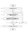
図9は、画像を合成する処理の手順を示すフローチャートである。まず、入力画像枚数nを設定する(ステップS1)。例えば、図3の構成では、3つの顕微鏡対物レンズユニットによって画像の取得が行なわれているので、入力画像枚数nには3が設定される。続いて、処理回数Nの初期値1が設定される(ステップS2)。
FIG. 9 is a flowchart illustrating a processing procedure for synthesizing an image. First, the number n of input images is set (step S1). For example, in the configuration of FIG. 3, since the image is acquired by three microscope objective lens units, 3 is set as the number n of input images. Subsequently, an
続いて、画像処理部21では、重複画像抽出部211において、画像Iaの画像データと画像Ibの画像データから、重複領域を抽出する(ステップS3)。そして、合成位置決定部212において、画像Iaと画像Ibの相対位置を変えながら重複領域の画像を比較し、重複領域が一致するときの画像Iaと画像Ibの相対位置を決定する(ステップS4)。
Subsequently, in the
ステップS4の処理が終わると、処理回数が規定回数に達したか否かが判断される(ステップ5)。処理回数が規定回数に達していない場合、ステップ3に戻って、今度は、画像Ibと画像Icについて、同様の処理が行なわれる。これにより、画像Ia、Ib、Icの相対位置が決まる。 When the process of step S4 ends, it is determined whether or not the number of processes has reached a specified number (step 5). If the number of processes has not reached the specified number, the process returns to step 3 and the same process is performed on the images Ib and Ic. Thereby, the relative positions of the images Ia, Ib, and Ic are determined.
処理回数が規定回数に達すると、観察画像合成部213において、合成位置決定部212の情報に基づいて、画像Ia、Ib、Icをつなぎ合わせて、3つの画像を1つの画像に合成する(ステップS6)。このようにして、標本Sの合成画像が生成される。
When the number of processing times reaches the specified number, the observation
また、本実施形態の顕微鏡システムは、複数の顕微鏡対物レンズと標本を光軸方向に相対的に動かす移動機構を有し、複数の顕微鏡対物レンズと標本を光軸方向に相対的に動かしながら合成画像を複数取得し、複数の合成画像を合成することが好ましい。 In addition, the microscope system of the present embodiment has a moving mechanism that moves the plurality of microscope objective lenses and the sample relatively in the optical axis direction, and combines them while moving the plurality of microscope objective lenses and the sample relatively in the optical axis direction. It is preferable to acquire a plurality of images and combine a plurality of composite images.
撮像範囲が広がった場合、一度の撮像で、撮像範囲の全域でピントのあった画像を得ることが困難になることがある。例えば、標本Sの標本面が、顕微鏡対物レンズユニット11の光軸に対して傾いている(直交していない)場合がある。このような場合、画像Ib(顕微鏡対物レンズ11b)はピントの合った画像になるが、画像IaやIc(顕微鏡対物レンズ11a、11c)はピントの合っていない画像になる。
When the imaging range is expanded, it may be difficult to obtain an image that is in focus throughout the imaging range with a single imaging. For example, the sample surface of the sample S may be inclined (not orthogonal) with respect to the optical axis of the microscope
そこで、顕微鏡対物レンズユニット11と標本Sの間隔を変化させながら、画像の取得を行なう。具体的には、照準機構7を動作させ、ピントの合った画像Iaが取得できる位置に、ステージを移動させる。そして、この位置から徐々に、ステージを顕微鏡対物レンズに近づける、あるいは離していく。この時、照準機構7の動作をステップ状に行なう(ステージの移動と停止を交互に行なう)。そして、各ステップで、画像Ia、Ib、Icの取得と、画像合成を行なう(画像Ia、Ib、Icを1つの画像に合成する)。
Therefore, an image is acquired while changing the interval between the microscope
続いて、合成画像の各々で、最もコントラストの高い画像領域を抽出する。そして、抽出した画像を合成する。このようにすることで、標本Sが傾くことで標本Sの合焦位置が光軸方向にずれていても、撮像範囲の全域でピントのあった画像を得ることができる。 Subsequently, an image area with the highest contrast is extracted from each of the composite images. Then, the extracted images are synthesized. By doing in this way, even if the in-focus position of the specimen S is shifted in the optical axis direction due to the inclination of the specimen S, it is possible to obtain a focused image in the entire imaging range.
このような処理は、画像処理部21において行なえばよい。なお、照準機構7の動作にはステッピングモーターや圧電素子を使用することができる。
Such processing may be performed in the
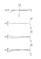
次に、第1の顕微鏡対物レンズ、第2の顕微鏡対物レンズ及び結像レンズの数値例を説明する。第1の顕微鏡対物レンズのレンズ断面図を図10に、第2の顕微鏡対物レンズレンズ断面図を図12に、結像レンズのレンズ断面図を図14に示す。また、図16は、第2の顕微鏡対物レンズと結像レンズを組み合わせたときのレンズ断面図である。 Next, numerical examples of the first microscope objective lens, the second microscope objective lens, and the imaging lens will be described. FIG. 10 shows a lens cross-sectional view of the first microscope objective lens, FIG. 12 shows a cross-sectional view of the second microscope objective lens, and FIG. 14 shows a lens cross-sectional view of the imaging lens. FIG. 16 is a lens cross-sectional view when the second microscope objective lens and the imaging lens are combined.
以下すべてのレンズ断面図中、L1、L2、L3、L4、L5、L11、L12、L13、L14、L15、は各レンズである。また、OBJは物面であって、標本面に対応する。また、IMGは像面であって、撮像素子の撮像面に対応する。また、GC1とGC2の各々は、カバーガラスを示している。 In the following lens cross-sectional views, L1, L2, L3, L4, L5, L11, L12, L13, L14, and L15 are lenses. Moreover, OBJ is an object surface and corresponds to a sample surface. Further, IMG is an image plane and corresponds to the imaging plane of the imaging element. Each of GC1 and GC2 indicates a cover glass.
第1の顕微鏡対物レンズは、図10に示すように、物体側より順に、両凹負レンズL1と、物体側に凸面を向けた正メニスカスレンズL2と、物体側に凸面を向けた正メニスカスレンズL3と、像側に凸面を向けた負メニスカスレンズL4と、両凸正レンズL5と、で構成されている。 As shown in FIG. 10, the first microscope objective lens includes, in order from the object side, a biconcave negative lens L1, a positive meniscus lens L2 having a convex surface facing the object side, and a positive meniscus lens having a convex surface facing the object side. L3, a negative meniscus lens L4 having a convex surface facing the image side, and a biconvex positive lens L5.
非球面は、両凹負レンズL1の両面と、正メニスカスレンズL2の両面と、正メニスカスレンズL3の両面と、負メニスカスレンズL4の両面と、両凸正レンズL5の両面との、10面に用いられている。 The aspheric surface has 10 surfaces including both surfaces of the biconcave negative lens L1, both surfaces of the positive meniscus lens L2, both surfaces of the positive meniscus lens L3, both surfaces of the negative meniscus lens L4, and both surfaces of the biconvex positive lens L5. It is used.
以上の第1の顕微鏡対物レンズの収差図を図11に示す。収差図において、(a)、(b)、(c)、(d)の各々は、球面収差(SA)、非点収差(AS)、歪曲収差(DT)、軸外横収差(コマ収差、倍率色収差、DY)を示す。各図中、NAは物体側の開口数を、FIYは最大像高を示す。これらの参照符号は、以下、すべての収差図において同様である。 FIG. 11 shows aberration diagrams of the first microscope objective lens described above. In the aberration diagrams, each of (a), (b), (c), and (d) includes spherical aberration (SA), astigmatism (AS), distortion (DT), off-axis lateral aberration (coma aberration, Chromatic aberration of magnification, DY). In each figure, NA represents the numerical aperture on the object side, and FIY represents the maximum image height. These reference numerals are the same in all aberration diagrams hereinafter.
第2の顕微鏡対物レンズは、図12に示すように、物体側より順に、像側に凸面を向けた負メニスカスレンズL1と、像側に凸面を向けた正メニスカスレンズL2と、物体側に凸面を向けた正メニスカスレンズL3と、物体側に凸面を向けた負メニスカスレンズL4と、で構成されている。ここで、負メニスカスレンズL1と、正メニスカスレンズL2と、が接合されている。 As shown in FIG. 12, the second microscope objective lens includes, in order from the object side, a negative meniscus lens L1 having a convex surface facing the image side, a positive meniscus lens L2 having a convex surface facing the image side, and a convex surface facing the object side. And a negative meniscus lens L4 having a convex surface facing the object side. Here, the negative meniscus lens L1 and the positive meniscus lens L2 are cemented.
非球面は、負メニスカスレンズL1の物体側面の1面に用いられている。 The aspherical surface is used for one surface of the object side surface of the negative meniscus lens L1.
以上の第2の顕微鏡対物レンズの収差図を図13に示す。
結像レンズは、図14に示すように、像側より順に、両凸正レンズL11と、物体側に凸面を向けた負メニスカスレンズL12と、両凸正レンズL13と、像側に凸面を向けた負メニスカスレンズL14と、両凹負レンズL15と、で構成されている。
FIG. 13 shows aberration diagrams of the second microscope objective lens.
As shown in FIG. 14, the imaging lens has a biconvex positive lens L11, a negative meniscus lens L12 having a convex surface facing the object side, a biconvex positive lens L13, and a convex surface facing the image side, in order from the image side. And a negative meniscus lens L14 and a biconcave negative lens L15.
非球面は、両凸正レンズL11の両面と、負メニスカスレンズL12の両面と、両凸正レンズL13の両面と、負メニスカスレンズL14の両面と、両凹負レンズL15の両面との、10面に用いられている。 The aspherical surface has 10 surfaces including both surfaces of the biconvex positive lens L11, both surfaces of the negative meniscus lens L12, both surfaces of the biconvex positive lens L13, both surfaces of the negative meniscus lens L14, and both surfaces of the biconcave negative lens L15. It is used for.
また、結像レンズの収差図を図15に示す。 FIG. 15 shows aberration diagrams of the imaging lens.
以下に、上述の顕微鏡対物レンズ及び結像レンズの数値データを示す。rは各レンズ面の曲率半径、dは各レンズ面間の間隔、ndは各レンズのd線の屈折率、νdは各レンズのアッベ数である。また、*は非球面を表している。また、焦点距離は全系の焦点距離、NAは物体側の開口数である。 Below, the numerical data of the above-mentioned microscope objective lens and imaging lens are shown. r is the radius of curvature of each lens surface, d is the distance between the lens surfaces, nd is the refractive index of the d-line of each lens, and νd is the Abbe number of each lens. * Represents an aspherical surface. The focal length is the focal length of the entire system, and NA is the numerical aperture on the object side.
また、非球面形状は、xを光の進行方向を正とした光軸とし、yを光軸と直交する方向にとると、下記の式にて表される。
x=(y2/R)/[1+{1−(k+1)(y/R)2}1/2]
+ay4 +by6+cy8+dy10+ey12+fy14+gy16
ただし、Rは近軸曲率半径、kは円錐係数、a、b、c、d、e、f、gは各々4次、6次、8次、10次、12次、14次、16次の非球面係数である。また、非球面係数において、「e−n」(nは整数)は、「10−n」を示している。
The aspherical shape is expressed by the following equation, where x is an optical axis with the light traveling direction being positive, and y is a direction orthogonal to the optical axis.
x = (y 2 / R) / [1+ {1- (k + 1) (y / R) 2} 1/2]
+ Ay 4 + by 6 + cy 8 + dy 10 + ey 12 + fy 14 + gy 16
Where R is a paraxial radius of curvature, k is a conic coefficient, a, b, c, d, e, f, g are 4th, 6th, 8th, 10th, 12th, 14th, 16th, respectively. Aspheric coefficient. In the aspheric coefficient, “e−n” (n is an integer) indicates “10 −n ”.
第1の顕微鏡対物レンズ
単位mm
面データ
面番号 r d nd νd
物面 ∞ 0.00
1 ∞ 0.17 1.5163 64.1
2 ∞ 9.28
3* -25.64 0.41 1.5307 55.7
4* 1.61 0.55
5* 1.08 0.69 1.5307 55.7
6* 1.16 0.31
7* 1.27 0.55 1.5307 55.7
8* 2.82 0.63
9* -2.01 0.33 1.6349 23.9
10* -7.77 0.04
11* 8.27 0.70 1.5307 55.7
12* -1.74 7.73
13 ∞ 0.30 1.5688 56.4
像面 ∞
非球面データ
第3面
曲率半径 -25.64
k=3.4042e+002
a=-3.6894e-002,b=8.9862e-003,c=5.1275e-003,
d=-2.2514e-003
第4面
曲率半径 1.61
k=-1.6171e+000
a=-9.9451e-002,b=-3.8461e-003,c=3.0399e-002,
d=-1.1887e-002
第5面
曲率半径 1.08
k=-1.2590e+000
a=-1.7655e-002,b=-2.5790e-003
第6面
曲率半径 1.16
k=-8.6895e-001
a=-1.0585e-001,b=1.7929e-002,c=1.6927e-003
第7面
曲率半径 1.27
k=-1.5753e+000
a=-4.1155e-002,b=1.4678e-002
第8面
曲率半径 2.82
k=1.3514e+000
a=1.7655e-002,b=-3.3527e-003
第9面
曲率半径 -2.01
k=1.5046e+000
a=5.3763e-002,b=-2.9705e-002,c=-6.9808e-004
第10面
曲率半径 -7.77
k=3.5929e+000
a=3.4244e-002,b=-3.2268e-002,c=-2.1329e-003
第11面
曲率半径 8.27
k=-5.0000e+000
a=-1.3838e-002,b=-5.7848e-004,c=4.1265e-004
第12面
曲率半径 -1.74
k=-1.1539e+000
a=-2.5780e-002,b=-2.2360e-003,c=3.7672e-003
1st microscope objective lens unit mm
Surface data Surface number rd nd νd
Object ∞ 0.00
1 ∞ 0.17 1.5163 64.1
2 ∞ 9.28
3 * -25.64 0.41 1.5307 55.7
4 * 1.61 0.55
5 * 1.08 0.69 1.5307 55.7
6 * 1.16 0.31
7 * 1.27 0.55 1.5307 55.7
8 * 2.82 0.63
9 * -2.01 0.33 1.6349 23.9
10 * -7.77 0.04
11 * 8.27 0.70 1.5307 55.7
12 * -1.74 7.73
13 ∞ 0.30 1.5688 56.4
Image plane ∞
Aspheric data 3rd surface radius of curvature -25.64
k = 3.4042e + 002
a = -3.6894e-002, b = 8.9862e-003, c = 5.1275e-003,
d = -2.2514e-003
Fourth surface radius of curvature 1.61
k = -1.6171e + 000
a = -9.9451e-002, b = -3.8461e-003, c = 3.0399e-002,
d = -1.1887e-002
5th surface radius of curvature 1.08
k = -1.2590e + 000
a = -1.7655e-002, b = -2.5790e-003
6th curvature radius 1.16
k = -8.6895e-001
a = -1.0585e-001, b = 1.7929e-002, c = 1.6927e-003
7th surface radius of curvature 1.27
k = -1.5753e + 000
a = -4.1155e-002, b = 1.4678e-002
8th surface radius of curvature 2.82
k = 1.3514e + 000
a = 1.7655e-002, b = -3.3527e-003
9th surface radius of curvature -2.01
k = 1.5046e + 000
a = 5.3763e-002, b = -2.9705e-002, c = -6.9808e-004
10th surface radius of curvature -7.77
k = 3.5929e + 000
a = 3.4244e-002, b = -3.2268e-002, c = -2.1329e-003
Eleventh surface radius of curvature 8.27
k = -5.0000e + 000
a = -1.3838e-002, b = -5.7848e-004, c = 4.1265e-004
12th surface radius of curvature -1.74
k = -1.1539e + 000
a = -2.5780e-002, b = -2.2360e-003, c = 3.7672e-003
第2の顕微鏡対物レンズ
単位mm
面データ
面番号 r d nd νd
物面 ∞ 0.00
1 ∞ 0.17 1.5163 64.1
2 ∞ 6.42
3* -4.61 0.65 1.8503 32.3
4 -150.74 1.63 1.7292 54.7
5 -4.75 0.06
6 6.07 0.90 1.5952 67.7
7 115.28 0.06
8 2.51 0.81 1.5952 67.7
9 2.09
非球面データ
第3面
曲率半径 -4.61
k=9.1007e-001
a=-6.4093e-004,b=5.5827e-005,c=1.2432e-005
Second microscope objective unit mm
Surface data Surface number rd nd νd
Object ∞ 0.00
1 ∞ 0.17 1.5163 64.1
2 ∞ 6.42
3 * -4.61 0.65 1.8503 32.3
4 -150.74 1.63 1.7292 54.7
5 -4.75 0.06
6 6.07 0.90 1.5952 67.7
7 115.28 0.06
8 2.51 0.81 1.5952 67.7
9 2.09
Aspheric data 3rd surface radius of curvature -4.61
k = 9.1007e-001
a = -6.4093e-004, b = 5.5827e-005, c = 1.2432e-005
結像レンズ
単位mm
面データ
面番号 r d nd νd
物面 ∞ ∞
1* 1.75 0.56 1.5346 56.2
2* -8.78 0.05
3* 5.32 0.35 1.6142 25.6
4* 1.59 0.35
5* 16.62 0.46 1.5346 56.2
6* -7.74 0.45
7* -2.04 0.47 1.5346 56.2
8* -0.99 0.47
9* -2.92 0.38 1.5346 56.2
10* 2.43 0.93
11 ∞ 0.30 1.5688 56.4
像面 ∞
非球面データ
第1面
曲率半径 1.75
k=-6.6472e-001
a=1.7752e-002,b=-7.8166e-003,c=2.7602e-003,
d=-4.2651e-003,e=4.0909e-003,f=1.8911e-003,
g=9.9189e-003
第2面
曲率半径 -8.78
k=-7.4134e+001
a=-6.2175e-003,b=3.3713e-002,c=-1.0145e-002,
d=3.3040e-003,e=6.2061e-003,f=1.7435e-002,
g=-5.4679e-003
第3面
曲率半径 5.32
k=-9.9352e+001
a=-3.0063e-002,b=6.8076e-002,c=-3.4746e-002,
d=2.9098e-002,e=5.6036e-003,f=4.5813e-003,
g=-2.2911e-002
第4面
曲率半径 1.59
k=5.9510e-001
a=-1.4632e-001,b=1.2471e-001,c=-6.3320e-002,
d=1.2893e-002,e=-1.3638e-003,f=-3.8744e-003,
g=-1.6260e-003
第5面
曲率半径 16.62
k=-4.2834e+002
a=-1.5273e-002,b=-9.0265e-003,c=3.0649e-002,
d=5.8923e-003,e=-1.7942e-003,f=-7.7961e-004,
g=-5.3525e-004
第6面
曲率半径 -7.74
k=-1.4002e+002
a=-5.2445e-002,b=3.5404e-002,c=-3.8982e-002,
d=1.4522e-002,e=4.4660e-003,f=7.4253e-004,
g=-4.2146e-004
第7面
曲率半径 -2.04
k=1.1476e+000
a=-4.4695e-002,b=1.2870e-001,c=-7.1027e-002,
d=1.2830e-002,e=1.4986e-003,f=5.4195e-005,
g=-3.6272e-004
第8面
曲率半径 -0.99
k=-1.0822e+000
a=8.2661e-002,b=-1.6805e-002,c=1.8282e-002,
d=-2.7597e-003,e=-3.0741e-004,f=-2.4855e-005,
g=-6.5291e-005
第9面
曲率半径 -2.92
k=-6.1166e+000
a=2.3788e-002,b=-2.9091e-002,c=5.6364e-003,
d=4.1246e-004,e=-1.3461e-004,f=-2.1375e-007,
g=5.3744e-007
第10面
曲率半径 2.43
k=-2.0265e+001
a=-4.3537e-002,b=7.4732e-003,c=-2.7053e-003,
d=3.9955e-004,e=-2.6524e-005,f=-4.6809e-007,
g=-1.2765e-008
Imaging lens unit mm
Surface data Surface number rd nd νd
Object ∞ ∞
1 * 1.75 0.56 1.5346 56.2
2 * -8.78 0.05
3 * 5.32 0.35 1.6142 25.6
4 * 1.59 0.35
5 * 16.62 0.46 1.5346 56.2
6 * -7.74 0.45
7 * -2.04 0.47 1.5346 56.2
8 * -0.99 0.47
9 * -2.92 0.38 1.5346 56.2
10 * 2.43 0.93
11 ∞ 0.30 1.5688 56.4
Image plane ∞
Aspheric data 1st surface radius of curvature 1.75
k = -6.6472e-001
a = 1.7752e-002, b = -7.8166e-003, c = 2.7602e-003,
d = -4.2651e-003, e = 4.0909e-003, f = 1.8911e-003,
g = 9.9189e-003
Second surface radius of curvature -8.78
k = -7.4134e + 001
a = -6.2175e-003, b = 3.3713e-002, c = -1.0145e-002,
d = 3.3040e-003, e = 6.2061e-003, f = 1.7435e-002,
g = -5.4679e-003
Third surface radius of curvature 5.32
k = -9.9352e + 001
a = -3.0063e-002, b = 6.8076e-002, c = -3.4746e-002,
d = 2.9098e-002, e = 5.6036e-003, f = 4.5813e-003,
g = -2.2911e-002
Fourth surface radius of curvature 1.59
k = 5.9510e-001
a = -1.4632e-001, b = 1.2471e-001, c = -6.3320e-002,
d = 1.2893e-002, e = -1.3638e-003, f = -3.8744e-003,
g = -1.6260e-003
5th curvature radius 16.62
k = -4.2834e + 002
a = -1.5273e-002, b = -9.0265e-003, c = 3.0649e-002,
d = 5.8923e-003, e = -1.7942e-003, f = -7.7961e-004,
g = -5.3525e-004
6th surface radius of curvature -7.74
k = -1.4002e + 002
a = -5.2445e-002, b = 3.5404e-002, c = -3.8982e-002,
d = 1.4522e-002, e = 4.4660e-003, f = 7.4253e-004,
g = -4.2146e-004
7th surface radius of curvature -2.04
k = 1.1476e + 000
a = -4.4695e-002, b = 1.2870e-001, c = -7.1027e-002,
d = 1.2830e-002, e = 1.4986e-003, f = 5.4195e-005,
g = -3.6272e-004
8th curvature radius -0.99
k = -1.0822e + 000
a = 8.2661e-002, b = -1.6805e-002, c = 1.8282e-002,
d = -2.7597e-003, e = -3.0741e-004, f = -2.4855e-005,
g = -6.5291e-005
9th surface radius of curvature -2.92
k = -6.1166e + 000
a = 2.3788e-002, b = -2.9091e-002, c = 5.6364e-003,
d = 4.1246e-004, e = -1.3461e-004, f = -2.1375e-007,
g = 5.3744e-007
10th surface radius of curvature 2.43
k = -2.0265e + 001
a = -4.3537e-002, b = 7.4732e-003, c = -2.7053e-003,
d = 3.9955e-004, e = -2.6524e-005, f = -4.6809e-007,
g = -1.2765e-008
以上のように、本発明に係る顕微鏡は、標本上の所望の範囲を、短い時間で撮像する場合に有用である。 As described above, the microscope according to the present invention is useful when imaging a desired range on a specimen in a short time.
1、1’ 顕微鏡
2 顕微鏡本体
3 光源
3’ 投光管
4 ステージ
5 XYハンドル
6 コンデンサレンズ
7 照準機構
8 表示装置
9 レボルバ
10 顕微鏡対物レンズユニット
11a、11b、11c 顕微鏡対物レンズ
12a、12b、12c 撮像素子
13 顕微鏡対物レンズユニット
14a、14b、14c 顕微鏡対物レンズ
15a、15b、15c 結像レンズ
16a、16b、16c 撮像素子
17 光源
18 遮光板
20 画像処理装置
21 画像処理部
22 制御部
23 表示部
24 記憶部
30 鏡筒
31 双眼部
100 顕微鏡システム
211 重複画像抽出部
212 合成位置決定部
213 観察画像合成部
CG1、CG2 カバーガラス
Ia、Ib、Ic 画像
IMG 像面
L1〜L5、L11〜L15 レンズ
La、Lb、Lc 撮像範囲
OBJ 物体面
S 標本
X1、X2 重複領域
DESCRIPTION OF
Claims (11)
前記複数の顕微鏡対物レンズの各々は、所定の広さの標本側撮像範囲を有し、
隣り合う前記顕微鏡対物レンズは、前記標本側撮像範囲の一部が重なるように配置されていることを特徴とする顕微鏡。 A microscope having a plurality of microscope objective lenses and an image sensor,
Each of the plurality of microscope objective lenses has a specimen-side imaging range of a predetermined area,
The adjacent microscope objective lens is disposed so that a part of the specimen-side imaging range overlaps.
Dmm<A<3Dmm (1)
ここで、
Aは、前記標本側撮像範囲の直径、
Dは、前記最も標本側のレンズの外形の直径、
である。 The microscope according to claim 4, wherein the following conditional expression (1) is satisfied.
Dmm <A <3Dmm (1)
here,
A is the diameter of the specimen-side imaging range,
D is the outer diameter of the lens on the most specimen side,
It is.
前記複数の顕微鏡対物レンズと標本を光軸方向に相対的に動かしながら合成画像を複数取得し、複数の前記合成画像を合成することを特徴とする請求項8に記載の顕微鏡システム。 A moving mechanism for moving the plurality of microscope objective lenses and the specimen relative to each other in the optical axis direction;
9. The microscope system according to claim 8, wherein a plurality of synthesized images are acquired while relatively moving the plurality of microscope objective lenses and the specimen in the optical axis direction, and the plurality of synthesized images are synthesized.
前記撮像ステップで得られた複数の画像を使って、合成画像を生成する画像生成ステップを有し、
前記撮像ステップにおいて、前記標本側撮像範囲の一部が重なるように撮像を行い、
前記画像生成ステップは、前記複数の画像から重複画像を抽出し、前記重複画像から、前記複数の画像の合成位置を決定し、前記合成位置の情報に基づいて、前記合成画像を生成することを特徴とする画像合成方法。 An imaging step of setting a plurality of specimen-side imaging ranges of a predetermined area and simultaneously imaging the plurality of specimen-side imaging ranges;
Using a plurality of images obtained in the imaging step, an image generation step of generating a composite image,
In the imaging step, imaging is performed so that a part of the specimen-side imaging range overlaps,
The image generation step includes extracting a duplicate image from the plurality of images, determining a combination position of the plurality of images from the overlap image, and generating the combination image based on the information of the combination position. A characteristic image composition method.
Priority Applications (1)
| Application Number | Priority Date | Filing Date | Title |
|---|---|---|---|
| JP2012139796A JP6006014B2 (en) | 2012-06-21 | 2012-06-21 | Microscope, microscope system, and image composition method |
Applications Claiming Priority (1)
| Application Number | Priority Date | Filing Date | Title |
|---|---|---|---|
| JP2012139796A JP6006014B2 (en) | 2012-06-21 | 2012-06-21 | Microscope, microscope system, and image composition method |
Publications (2)
| Publication Number | Publication Date |
|---|---|
| JP2014006291A true JP2014006291A (en) | 2014-01-16 |
| JP6006014B2 JP6006014B2 (en) | 2016-10-12 |
Family
ID=50104093
Family Applications (1)
| Application Number | Title | Priority Date | Filing Date |
|---|---|---|---|
| JP2012139796A Expired - Fee Related JP6006014B2 (en) | 2012-06-21 | 2012-06-21 | Microscope, microscope system, and image composition method |
Country Status (1)
| Country | Link |
|---|---|
| JP (1) | JP6006014B2 (en) |
Cited By (8)
| Publication number | Priority date | Publication date | Assignee | Title |
|---|---|---|---|---|
| CN107037576A (en) * | 2017-05-03 | 2017-08-11 | 中国科学院苏州生物医学工程技术研究所 | Optical microphotograph imaging device and its imaging method |
| CN107219610A (en) * | 2017-07-25 | 2017-09-29 | 浙江舜宇光学有限公司 | Imaging lens |
| WO2018051514A1 (en) * | 2016-09-16 | 2018-03-22 | オリンパス株式会社 | Observation device |
| JP2019525243A (en) * | 2016-07-25 | 2019-09-05 | ウニヴェルジテート ドゥイスブルク・エッセン | System for simultaneous videographic or photographic capture of multiple images |
| CN110346913A (en) * | 2014-10-31 | 2019-10-18 | 三星电机株式会社 | Optical system |
| CN114397751A (en) * | 2021-12-31 | 2022-04-26 | 北方信息控制研究院集团有限公司 | Guidance self-checking division photoelectric imaging detection microscope objective |
| US11815672B2 (en) | 2018-03-15 | 2023-11-14 | Evident Corporation | Observation device |
| EP4657132A1 (en) * | 2024-05-28 | 2025-12-03 | LensMakers Technologies Oy | Optical arrangement for microscope |
Citations (11)
| Publication number | Priority date | Publication date | Assignee | Title |
|---|---|---|---|---|
| JPH01309478A (en) * | 1988-02-23 | 1989-12-13 | Olympus Optical Co Ltd | Picture input and output device |
| JPH0654803A (en) * | 1992-06-09 | 1994-03-01 | Olympus Optical Co Ltd | Image pickup device for stereoscopic vision endoscope |
| JPH10155104A (en) * | 1996-11-22 | 1998-06-09 | Canon Inc | Compound eye imaging method and apparatus, and storage medium |
| JP2000036968A (en) * | 1998-07-21 | 2000-02-02 | Canon Inc | Compound eye imaging apparatus and compound eye imaging method |
| JP2001223931A (en) * | 2000-02-10 | 2001-08-17 | Olympus Optical Co Ltd | Image pickup device and image system |
| JP2002048978A (en) * | 2000-08-01 | 2002-02-15 | Olympus Optical Co Ltd | Objective lens unit, optical device having objective lens unit and observation method using the optical device |
| JP2002320133A (en) * | 2001-04-23 | 2002-10-31 | Nikon Corp | Electronic camera |
| JP2008076530A (en) * | 2006-09-19 | 2008-04-03 | Yokogawa Electric Corp | Microscope |
| JP2009055553A (en) * | 2007-08-29 | 2009-03-12 | Fujifilm Corp | Image pickup apparatus equipped with a plurality of image pickup elements |
| JP2010197872A (en) * | 2009-02-26 | 2010-09-09 | Olympus Corp | Apparatus for capturing sample image for virtual slide |
| JP2011004340A (en) * | 2009-06-22 | 2011-01-06 | Fujifilm Corp | Imaging apparatus and control method therefor |
-
2012
- 2012-06-21 JP JP2012139796A patent/JP6006014B2/en not_active Expired - Fee Related
Patent Citations (11)
| Publication number | Priority date | Publication date | Assignee | Title |
|---|---|---|---|---|
| JPH01309478A (en) * | 1988-02-23 | 1989-12-13 | Olympus Optical Co Ltd | Picture input and output device |
| JPH0654803A (en) * | 1992-06-09 | 1994-03-01 | Olympus Optical Co Ltd | Image pickup device for stereoscopic vision endoscope |
| JPH10155104A (en) * | 1996-11-22 | 1998-06-09 | Canon Inc | Compound eye imaging method and apparatus, and storage medium |
| JP2000036968A (en) * | 1998-07-21 | 2000-02-02 | Canon Inc | Compound eye imaging apparatus and compound eye imaging method |
| JP2001223931A (en) * | 2000-02-10 | 2001-08-17 | Olympus Optical Co Ltd | Image pickup device and image system |
| JP2002048978A (en) * | 2000-08-01 | 2002-02-15 | Olympus Optical Co Ltd | Objective lens unit, optical device having objective lens unit and observation method using the optical device |
| JP2002320133A (en) * | 2001-04-23 | 2002-10-31 | Nikon Corp | Electronic camera |
| JP2008076530A (en) * | 2006-09-19 | 2008-04-03 | Yokogawa Electric Corp | Microscope |
| JP2009055553A (en) * | 2007-08-29 | 2009-03-12 | Fujifilm Corp | Image pickup apparatus equipped with a plurality of image pickup elements |
| JP2010197872A (en) * | 2009-02-26 | 2010-09-09 | Olympus Corp | Apparatus for capturing sample image for virtual slide |
| JP2011004340A (en) * | 2009-06-22 | 2011-01-06 | Fujifilm Corp | Imaging apparatus and control method therefor |
Cited By (12)
| Publication number | Priority date | Publication date | Assignee | Title |
|---|---|---|---|---|
| CN110346913A (en) * | 2014-10-31 | 2019-10-18 | 三星电机株式会社 | Optical system |
| CN110346913B (en) * | 2014-10-31 | 2021-12-14 | 三星电机株式会社 | Optical system |
| JP2019525243A (en) * | 2016-07-25 | 2019-09-05 | ウニヴェルジテート ドゥイスブルク・エッセン | System for simultaneous videographic or photographic capture of multiple images |
| JP7033796B2 (en) | 2016-07-25 | 2022-03-11 | ウニヴェルジテート ドゥイスブルク・エッセン | A system for simultaneous videographic or photographic capture of multiple images |
| WO2018051514A1 (en) * | 2016-09-16 | 2018-03-22 | オリンパス株式会社 | Observation device |
| CN107037576A (en) * | 2017-05-03 | 2017-08-11 | 中国科学院苏州生物医学工程技术研究所 | Optical microphotograph imaging device and its imaging method |
| CN107037576B (en) * | 2017-05-03 | 2023-08-15 | 中国科学院苏州生物医学工程技术研究所 | Optical microscope imaging device and imaging method thereof |
| CN107219610A (en) * | 2017-07-25 | 2017-09-29 | 浙江舜宇光学有限公司 | Imaging lens |
| CN107219610B (en) * | 2017-07-25 | 2022-09-20 | 浙江舜宇光学有限公司 | Imaging lens |
| US11815672B2 (en) | 2018-03-15 | 2023-11-14 | Evident Corporation | Observation device |
| CN114397751A (en) * | 2021-12-31 | 2022-04-26 | 北方信息控制研究院集团有限公司 | Guidance self-checking division photoelectric imaging detection microscope objective |
| EP4657132A1 (en) * | 2024-05-28 | 2025-12-03 | LensMakers Technologies Oy | Optical arrangement for microscope |
Also Published As
| Publication number | Publication date |
|---|---|
| JP6006014B2 (en) | 2016-10-12 |
Similar Documents
| Publication | Publication Date | Title |
|---|---|---|
| JP6006014B2 (en) | Microscope, microscope system, and image composition method | |
| JP5885537B2 (en) | Microscope objective lens | |
| JP2016085335A (en) | Objective lens for microscope | |
| US11016281B2 (en) | Imaging optical system and microscope system | |
| JP2006184844A (en) | Imaging optical system and imaging apparatus using the same | |
| WO2013157470A1 (en) | Microscope objective lens | |
| JP2010266776A (en) | Eyepiece optical system and electronic view finder using the same | |
| CN111886531B (en) | Endoscope objective optical system | |
| JP2012093478A (en) | Eyepiece optical system having reflective surface, and electronic view finder using the same | |
| KR20080106076A (en) | Zoom lens system | |
| JP2013156579A (en) | Microscope objective lens | |
| JP2012252037A (en) | Zoom imaging optical system and microscope including the same | |
| JPWO2017068726A1 (en) | Imaging apparatus and optical apparatus including the same | |
| JP5624909B2 (en) | Microscope objective lens and microscope apparatus provided with the same | |
| JPWO2017216969A1 (en) | Bright relay optical system and optical system for rigid mirror using the same, rigid mirror | |
| US7253972B2 (en) | Telephoto lens system | |
| JP5277178B2 (en) | Telescope optics | |
| JP2017097263A (en) | Optical system and imaging apparatus having the same | |
| US11150454B2 (en) | Microscope pupil relay optical system and microscope device | |
| JPWO2020021662A1 (en) | Microscope objectives and microscopes | |
| JP2009223085A (en) | Imaging apparatus and vein authentication apparatus using the same | |
| JP2013109081A (en) | Inverted microscope | |
| JPWO2017221334A1 (en) | Imaging optical system for microscope and light field microscope apparatus | |
| JP2020154190A (en) | Observation optical system and image display device having it | |
| JP2013221956A (en) | Microscope |
Legal Events
| Date | Code | Title | Description |
|---|---|---|---|
| A621 | Written request for application examination |
Free format text: JAPANESE INTERMEDIATE CODE: A621 Effective date: 20150521 |
|
| A977 | Report on retrieval |
Free format text: JAPANESE INTERMEDIATE CODE: A971007 Effective date: 20160427 |
|
| A131 | Notification of reasons for refusal |
Free format text: JAPANESE INTERMEDIATE CODE: A131 Effective date: 20160601 |
|
| A521 | Request for written amendment filed |
Free format text: JAPANESE INTERMEDIATE CODE: A523 Effective date: 20160729 |
|
| TRDD | Decision of grant or rejection written | ||
| A01 | Written decision to grant a patent or to grant a registration (utility model) |
Free format text: JAPANESE INTERMEDIATE CODE: A01 Effective date: 20160831 |
|
| A61 | First payment of annual fees (during grant procedure) |
Free format text: JAPANESE INTERMEDIATE CODE: A61 Effective date: 20160908 |
|
| R151 | Written notification of patent or utility model registration |
Ref document number: 6006014 Country of ref document: JP Free format text: JAPANESE INTERMEDIATE CODE: R151 |
|
| LAPS | Cancellation because of no payment of annual fees |