JP2014002382A - Nano-projector panel formed by arrayed liquid crystal cells - Google Patents
Nano-projector panel formed by arrayed liquid crystal cells Download PDFInfo
- Publication number
- JP2014002382A JP2014002382A JP2013124906A JP2013124906A JP2014002382A JP 2014002382 A JP2014002382 A JP 2014002382A JP 2013124906 A JP2013124906 A JP 2013124906A JP 2013124906 A JP2013124906 A JP 2013124906A JP 2014002382 A JP2014002382 A JP 2014002382A
- Authority
- JP
- Japan
- Prior art keywords
- mos control
- annular body
- control transistor
- layer
- cell
- Prior art date
- Legal status (The legal status is an assumption and is not a legal conclusion. Google has not performed a legal analysis and makes no representation as to the accuracy of the status listed.)
- Granted
Links
Images


Classifications
-
- G—PHYSICS
- G02—OPTICS
- G02F—OPTICAL DEVICES OR ARRANGEMENTS FOR THE CONTROL OF LIGHT BY MODIFICATION OF THE OPTICAL PROPERTIES OF THE MEDIA OF THE ELEMENTS INVOLVED THEREIN; NON-LINEAR OPTICS; FREQUENCY-CHANGING OF LIGHT; OPTICAL LOGIC ELEMENTS; OPTICAL ANALOGUE/DIGITAL CONVERTERS
- G02F1/00—Devices or arrangements for the control of the intensity, colour, phase, polarisation or direction of light arriving from an independent light source, e.g. switching, gating or modulating; Non-linear optics
- G02F1/01—Devices or arrangements for the control of the intensity, colour, phase, polarisation or direction of light arriving from an independent light source, e.g. switching, gating or modulating; Non-linear optics for the control of the intensity, phase, polarisation or colour
- G02F1/13—Devices or arrangements for the control of the intensity, colour, phase, polarisation or direction of light arriving from an independent light source, e.g. switching, gating or modulating; Non-linear optics for the control of the intensity, phase, polarisation or colour based on liquid crystals, e.g. single liquid crystal display cells
- G02F1/133—Constructional arrangements; Operation of liquid crystal cells; Circuit arrangements
- G02F1/136—Liquid crystal cells structurally associated with a semi-conducting layer or substrate, e.g. cells forming part of an integrated circuit
- G02F1/1362—Active matrix addressed cells
- G02F1/1368—Active matrix addressed cells in which the switching element is a three-electrode device
-
- G—PHYSICS
- G02—OPTICS
- G02F—OPTICAL DEVICES OR ARRANGEMENTS FOR THE CONTROL OF LIGHT BY MODIFICATION OF THE OPTICAL PROPERTIES OF THE MEDIA OF THE ELEMENTS INVOLVED THEREIN; NON-LINEAR OPTICS; FREQUENCY-CHANGING OF LIGHT; OPTICAL LOGIC ELEMENTS; OPTICAL ANALOGUE/DIGITAL CONVERTERS
- G02F1/00—Devices or arrangements for the control of the intensity, colour, phase, polarisation or direction of light arriving from an independent light source, e.g. switching, gating or modulating; Non-linear optics
- G02F1/01—Devices or arrangements for the control of the intensity, colour, phase, polarisation or direction of light arriving from an independent light source, e.g. switching, gating or modulating; Non-linear optics for the control of the intensity, phase, polarisation or colour
- G02F1/13—Devices or arrangements for the control of the intensity, colour, phase, polarisation or direction of light arriving from an independent light source, e.g. switching, gating or modulating; Non-linear optics for the control of the intensity, phase, polarisation or colour based on liquid crystals, e.g. single liquid crystal display cells
- G02F1/133—Constructional arrangements; Operation of liquid crystal cells; Circuit arrangements
- G02F1/136—Liquid crystal cells structurally associated with a semi-conducting layer or substrate, e.g. cells forming part of an integrated circuit
- G02F1/1362—Active matrix addressed cells
- G02F1/136209—Light shielding layers, e.g. black matrix, incorporated in the active matrix substrate, e.g. structurally associated with the switching element
-
- G—PHYSICS
- G02—OPTICS
- G02F—OPTICAL DEVICES OR ARRANGEMENTS FOR THE CONTROL OF LIGHT BY MODIFICATION OF THE OPTICAL PROPERTIES OF THE MEDIA OF THE ELEMENTS INVOLVED THEREIN; NON-LINEAR OPTICS; FREQUENCY-CHANGING OF LIGHT; OPTICAL LOGIC ELEMENTS; OPTICAL ANALOGUE/DIGITAL CONVERTERS
- G02F1/00—Devices or arrangements for the control of the intensity, colour, phase, polarisation or direction of light arriving from an independent light source, e.g. switching, gating or modulating; Non-linear optics
- G02F1/01—Devices or arrangements for the control of the intensity, colour, phase, polarisation or direction of light arriving from an independent light source, e.g. switching, gating or modulating; Non-linear optics for the control of the intensity, phase, polarisation or colour
- G02F1/13—Devices or arrangements for the control of the intensity, colour, phase, polarisation or direction of light arriving from an independent light source, e.g. switching, gating or modulating; Non-linear optics for the control of the intensity, phase, polarisation or colour based on liquid crystals, e.g. single liquid crystal display cells
- G02F1/133—Constructional arrangements; Operation of liquid crystal cells; Circuit arrangements
- G02F1/136—Liquid crystal cells structurally associated with a semi-conducting layer or substrate, e.g. cells forming part of an integrated circuit
- G02F1/1362—Active matrix addressed cells
- G02F1/136213—Storage capacitors associated with the pixel electrode
-
- G—PHYSICS
- G02—OPTICS
- G02F—OPTICAL DEVICES OR ARRANGEMENTS FOR THE CONTROL OF LIGHT BY MODIFICATION OF THE OPTICAL PROPERTIES OF THE MEDIA OF THE ELEMENTS INVOLVED THEREIN; NON-LINEAR OPTICS; FREQUENCY-CHANGING OF LIGHT; OPTICAL LOGIC ELEMENTS; OPTICAL ANALOGUE/DIGITAL CONVERTERS
- G02F1/00—Devices or arrangements for the control of the intensity, colour, phase, polarisation or direction of light arriving from an independent light source, e.g. switching, gating or modulating; Non-linear optics
- G02F1/01—Devices or arrangements for the control of the intensity, colour, phase, polarisation or direction of light arriving from an independent light source, e.g. switching, gating or modulating; Non-linear optics for the control of the intensity, phase, polarisation or colour
- G02F1/13—Devices or arrangements for the control of the intensity, colour, phase, polarisation or direction of light arriving from an independent light source, e.g. switching, gating or modulating; Non-linear optics for the control of the intensity, phase, polarisation or colour based on liquid crystals, e.g. single liquid crystal display cells
- G02F1/133—Constructional arrangements; Operation of liquid crystal cells; Circuit arrangements
- G02F1/136—Liquid crystal cells structurally associated with a semi-conducting layer or substrate, e.g. cells forming part of an integrated circuit
- G02F1/1362—Active matrix addressed cells
- G02F1/136277—Active matrix addressed cells formed on a semiconductor substrate, e.g. of silicon
-
- H—ELECTRICITY
- H01—ELECTRIC ELEMENTS
- H01L—SEMICONDUCTOR DEVICES NOT COVERED BY CLASS H10
- H01L33/00—Semiconductor devices with at least one potential-jump barrier or surface barrier specially adapted for light emission; Processes or apparatus specially adapted for the manufacture or treatment thereof or of parts thereof; Details thereof
- H01L33/36—Semiconductor devices with at least one potential-jump barrier or surface barrier specially adapted for light emission; Processes or apparatus specially adapted for the manufacture or treatment thereof or of parts thereof; Details thereof characterised by the electrodes
-
- G—PHYSICS
- G02—OPTICS
- G02F—OPTICAL DEVICES OR ARRANGEMENTS FOR THE CONTROL OF LIGHT BY MODIFICATION OF THE OPTICAL PROPERTIES OF THE MEDIA OF THE ELEMENTS INVOLVED THEREIN; NON-LINEAR OPTICS; FREQUENCY-CHANGING OF LIGHT; OPTICAL LOGIC ELEMENTS; OPTICAL ANALOGUE/DIGITAL CONVERTERS
- G02F1/00—Devices or arrangements for the control of the intensity, colour, phase, polarisation or direction of light arriving from an independent light source, e.g. switching, gating or modulating; Non-linear optics
- G02F1/01—Devices or arrangements for the control of the intensity, colour, phase, polarisation or direction of light arriving from an independent light source, e.g. switching, gating or modulating; Non-linear optics for the control of the intensity, phase, polarisation or colour
- G02F1/13—Devices or arrangements for the control of the intensity, colour, phase, polarisation or direction of light arriving from an independent light source, e.g. switching, gating or modulating; Non-linear optics for the control of the intensity, phase, polarisation or colour based on liquid crystals, e.g. single liquid crystal display cells
- G02F1/133—Constructional arrangements; Operation of liquid crystal cells; Circuit arrangements
- G02F1/136—Liquid crystal cells structurally associated with a semi-conducting layer or substrate, e.g. cells forming part of an integrated circuit
- G02F1/1362—Active matrix addressed cells
- G02F1/136277—Active matrix addressed cells formed on a semiconductor substrate, e.g. of silicon
- G02F1/136281—Active matrix addressed cells formed on a semiconductor substrate, e.g. of silicon having a transmissive semiconductor substrate
Abstract
Description
本開示は、配列された液晶セルから形成され、ナノプロジェクタに使用されるためのパネルに関する。 The present disclosure relates to panels formed from aligned liquid crystal cells and used for nanoprojectors.
図1は、画像を投影するためにナノプロジェクタに使用されるパネルを概略的に示している。 FIG. 1 schematically shows a panel used in a nanoprojector to project an image.
パネル1 は、図1に拡大図5 で示されている配列されたセル3 を備えている。各セル3 は、図1には示されていない上側透明電極及び下側透明電極に囲まれた液晶層7 を有している。各セル3 は、上側透明電極の上側に設けられたMOS 制御トランジスタ9 を更に有している。MOS 制御トランジスタ9 は、行デコーダ11及び列デコーダ13に接続されている。パネル1 は、セル3 のスイッチオンを同期させることが可能な駆動回路15を更に備えている。
Panel 1 comprises an array of
光源17によって照射された光がパネル1 を横切り、画像がスクリーン(不図示)に投影される。
The light irradiated by the
図2は、図1に示されたタイプのパネルの動作を示す電気回路図である。 FIG. 2 is an electric circuit diagram showing the operation of the panel of the type shown in FIG.
セル3 毎に、上側透明電極及び下側透明電極に囲まれた液晶層7 はコンデンサ21を形成する。コンデンサ21の上側透明電極は、セル3 のMOS 制御トランジスタ9 の主電極に接続されている。MOS 制御トランジスタ9 によってセル3 の光減衰レベルを制御することが可能になる。
For each
各MOS 制御トランジスタ9 のゲートが行23に接続されている。各MOS 制御トランジスタ9 のソースが列25に接続されている。投影される画像に対応する階調が、各列25に送られた電圧の値に応じて各セル3 に伝送される。このような階調の値は、MOS 制御トランジスタ9 に行23毎に伝送される。
The gate of each
各液晶セルのコンデンサ21の容量値は低く、例えば数fF程度である。MOS 制御トランジスタ9 のレベルでの漏れ電流は、2つの画像リフレッシュ動作間で信号の損失を引き起こす。それ故、蓄積コンデンサ27が設けられており、画像データを十分に長い間蓄積するためにコンデンサ21と並列に配置されている。
The capacitance value of the
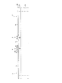
図3は、図1に示されたタイプのパネルの一部を概略的に示す断面図である。点線31がセル3 を画定している。
FIG. 3 is a cross-sectional view schematically showing a part of a panel of the type shown in FIG. Dotted
各セル3 は、下側透明電極33及び上側透明電極35に囲まれた液晶層7 を有している。下側透明電極33は透明板32上に置かれている。下側透明電極33は液晶層7 の下に連なって設けられており、全てのセル3 に共通である一方、上側透明電極35は夫々のセル3 に関連付けられている。上側透明電極35は、セル3 を短絡させないために互いに離隔して配置されている。
Each
層39で覆われた酸化シリコン層37が、上側透明電極35の上に配置されている。パネルの製造に関する実施形態で以下に記述されているように、酸化シリコン層37及び層39は夫々、現在BOX (Buried OXide)と称される埋め込み酸化物層、及びシリコンオンインシュレータ(SOI )タイプの基板の活性層に相当する。
A
セル3 毎に、MOS 制御トランジスタ9 が、層39のシリコン領域40に形成されており、層39の残りの領域41が酸化している。残りの領域41は透明であることに注目すべきである。各MOS 制御トランジスタ9 はゲート42を有しており、ゲート42は、シリコン領域40の上側に設けられており、ゲート絶縁体43によってシリコン領域40から絶縁されている。スペーサ45がゲート42を囲んでいる。ソース及びドレインの領域47がシリコン領域40内のゲート42の両側に設けられている。
For each
層39の残りの領域41及びMOS 制御トランジスタ9 は絶縁層51によって覆われており、絶縁層51自体は、複数の絶縁層によって分離された複数の金属被覆層53で覆われている。例えば、参照番号55〜60で示された6つの金属被覆層53がある。透明板54がこの構造体を覆っている。
The
セル3 毎に、導電性材料から形成されたバイア61が、MOS 制御トランジスタ9 の主電極に接続された下方の金属被覆層55の金属被覆体を上側透明電極35に接続している。
For each
一般に、下方の金属被覆層55及び中間の金属被覆層56は、MOS 制御トランジスタ9 のソースコンタクト、ドレインコンタクト及びゲートコンタクトの接続部分を形成するために使用される。上方の金属被覆層60はセル3 に電力を供給するために使用される。
In general, the
セル3 毎に、上方の金属被覆層60は、MOS 制御トランジスタ9 の上側を覆っており、MOS 制御トランジスタ9 を光線から保護するための光学的な遮蔽体として使用される。
For each
6つの金属被覆層を有するセルの場合、少なくとも2つの金属被覆層、例えば中間の金属被覆層57,58,59が残っており、これらの層は、MOS 制御トランジスタ9 の上側で一体化されたMIM (金属−絶縁体−金属)コンデンサを形成するために使用されてもよく、このようなMIM コンデンサは、セル3 の蓄積コンデンサ27を形成している。
In the case of a cell with six metallization layers, there remain at least two metallization layers, for example
更に、各セル3 の有効表面積は、光線によって横切られ得るセル3 の表面積に相当し、MOS 制御トランジスタ9 によって占められる表面積が除外される。
Furthermore, the effective surface area of each
図3に示されたタイプのパネルがナノプロジェクタに使用されるとき、非常に強い光の流れが、MOS 制御トランジスタの側でパネルの表面に達する。 When a panel of the type shown in FIG. 3 is used in a nanoprojector, a very strong light flow reaches the surface of the panel on the side of the MOS control transistor.
このようなパネルの欠点は、MOS 制御トランジスタに直接達する光線を遮るために上方の金属被覆層が設けられているにも関わらず、MOS 制御トランジスタの動作が寄生放射によって妨げられることである。その結果、MOS 制御トランジスタの漏れ電流が大きくなる。 The disadvantage of such a panel is that the operation of the MOS control transistor is hindered by parasitic radiation, although an upper metallization layer is provided to block light directly reaching the MOS control transistor. As a result, the leakage current of the MOS control transistor increases.
このようなパネルの別の欠点は、MOS 制御トランジスタの上側で複数の金属被覆層内に各セルの蓄積コンデンサを一体化し得るために、MOS 制御トランジスタの上側に少なくとも5から6の金属被覆層を形成する必要性があることである。 Another disadvantage of such a panel is that at least 5 to 6 metallization layers are provided on the upper side of the MOS control transistor so that the storage capacitor of each cell can be integrated into the metallization layers on the upper side of the MOS control transistor. There is a need to form.
現在、ナノプロジェクタに使用されるためのパネルの製造コストを減らすために、MOS 制御トランジスタの上側に形成される金属被覆層の数を減らす必要がある。5未満の金属被覆層、例えば3つの金属被覆層のみの形成が望まれている場合、セルの蓄積コンデンサはMOS 制御トランジスタの上側に一体化されることができず、金属被覆層は全て、MOS 制御トランジスタのソースコンタクト、ドレインコンタクト及びゲートコンタクトの接続部分を形成するため、且つセルに電力を供給するために使用される。それ故、セル毎に、蓄積コンデンサがMOS 制御トランジスタの隣りに、例えばMOS コンデンサの形態で形成される。そのため、各パネルの有効表面積が減少する。 Currently, in order to reduce the manufacturing cost of panels for use in nanoprojectors, it is necessary to reduce the number of metal cladding layers formed on top of MOS control transistors. If it is desired to form less than 5 metallization layers, for example only 3 metallization layers, the cell storage capacitor cannot be integrated on top of the MOS control transistor and all metallization layers are MOS Used to form the connection of the source contact, drain contact and gate contact of the control transistor and to supply power to the cell. Therefore, for each cell, a storage capacitor is formed next to the MOS control transistor, for example in the form of a MOS capacitor. This reduces the effective surface area of each panel.
このように、上述したパネルの欠点の少なくとも一部を克服する、ナノプロジェクタに使用されるための液晶セル配列から形成されたパネルの必要性がある。 Thus, there is a need for a panel formed from a liquid crystal cell array for use in a nanoprojector that overcomes at least some of the disadvantages of the panel described above.
従って、本発明の実施形態の目的は、MOS 制御トランジスタが光線から保護される、ナノプロジェクタに使用されるための液晶セル配列から形成されたパネルを提供することである。 Accordingly, it is an object of embodiments of the present invention to provide a panel formed from a liquid crystal cell array for use in a nanoprojector in which the MOS control transistor is protected from light.
本発明の実施形態の別の目的は、3つの金属被覆層のみで覆われたMOS 制御トランジスタを備えており、蓄積コンデンサが、セルの有効表面積を減少させずにセル毎にセルに一体化されている、ナノプロジェクタに使用されるための液晶セル配列から形成されたパネルを提供することである。 Another object of embodiments of the present invention is to provide a MOS control transistor covered only with three metallization layers, and the storage capacitor is integrated into the cell for each cell without reducing the effective surface area of the cell. It is to provide a panel formed from a liquid crystal cell array for use in a nanoprojector.
これらの目的を達成するために、本発明の実施形態は、配列されたセルから形成され、ナノプロジェクタに使用されるためのパネルであって、各セルは、上側透明電極及び下側透明電極に囲まれた液晶層を有しており、前記上側透明電極の上側にMOS 制御トランジスタが配置されており、該MOS 制御トランジスタは、少なくとも3つの金属被覆層で覆われていることを特徴とするパネルを提供する。4つの隣り合う前記セルの集合体のMOS 制御トランジスタが前記集合体の中央部に配置されているように、各セルのMOS 制御トランジスタは前記セルの隅部に設けられており、上方の前記金属被覆層は、前記4つの隣り合うセルの集合体のMOS 制御トランジスタの上側を覆っており、前記パネルは、前記4つの隣り合うセルの集合体毎に、前記MOS 制御トランジスタを囲む導電性の第1の環状体を備えており、該第1の環状体は、下方の前記金属被覆層から絶縁体を介して各セルの前記上側透明電極に延びている。 In order to achieve these objectives, embodiments of the present invention are panels formed from arrayed cells and used in nanoprojectors, each cell being an upper transparent electrode and a lower transparent electrode. A panel having an enclosed liquid crystal layer, wherein a MOS control transistor is disposed above the upper transparent electrode, and the MOS control transistor is covered with at least three metal coating layers. I will provide a. The MOS control transistor of each cell is provided at the corner of the cell so that the MOS control transistor of the assembly of four adjacent cells is arranged in the center of the assembly, The covering layer covers the upper side of the MOS control transistor of the group of four adjacent cells, and the panel includes a conductive first layer surrounding the MOS control transistor for each group of the four adjacent cells. The first annular body extends from the lower metal coating layer to the upper transparent electrode of each cell via an insulator.
本発明の実施形態によれば、前記パネルは、前記4つの隣り合うセルの集合体毎に、前記MOS 制御トランジスタを囲み、前記第1の環状体の上側に設けられた導電性の第2の環状体及び導電性の第3の環状体を更に備えており、前記第2の環状体は、中間の前記金属被覆層から前記下方の金属被覆層に延びており、前記第3の環状体は、前記上方の金属被覆層から前記中間の金属被覆層に延びている。 According to an embodiment of the present invention, the panel surrounds the MOS control transistor for each of the four adjacent cell assemblies, and includes a conductive second electrode provided on the upper side of the first annular body. An annular body and a conductive third annular body, wherein the second annular body extends from the intermediate metal coating layer to the lower metal coating layer, and the third annular body comprises: , Extending from the upper metal coating layer to the intermediate metal coating layer.
本発明の実施形態によれば、前記パネルは、前記セル毎に、前記MOS 制御トランジスタの主電極に接続された前記下方の金属被覆層の金属被覆体から前記上側透明電極に延びる導電性のバイアを更に備えている。 According to an embodiment of the present invention, the panel includes, for each cell, a conductive via extending from the metal cover of the lower metal cover layer connected to the main electrode of the MOS control transistor to the upper transparent electrode. Is further provided.
本発明の実施形態によれば、前記第1の環状体の幅が0.2 乃至0.3 μm である。 According to an embodiment of the present invention, the width of the first annular body is 0.2 to 0.3 μm.
本発明の実施形態によれば、前記絶縁体は酸化シリコンから形成されており、1乃至5nmの厚さを有している。 According to an embodiment of the present invention, the insulator is made of silicon oxide and has a thickness of 1 to 5 nm.
本発明の実施形態は、配列されたセルから形成され、ナノプロジェクタに使用されるためのパネルを製造するための方法であって、半導体層で覆われた第1の絶縁層によって覆われた半導体基板を備えたウエハを準備する工程と、4つの隣り合うセル夫々のMOS 制御トランジスタが前記4つの隣り合うセルの集合体の中央部に配置されるように、各セルの隅部であって前記半導体層の活性領域に各セルのMOS 制御トランジスタを形成し、前記半導体層の残りの領域を酸化させる工程と、形成された構造体に第2の絶縁層を堆積させ、前記4つの隣り合うセルの集合体のMOS 制御トランジスタを囲む第1の開口部を前記第2の絶縁層の上側から前記半導体基板に至るまで形成する工程と、前記第1の開口部に導電性材料を充填して導電性の第1の環状体を形成する工程と、各MOS 制御トランジスタの上側に少なくとも3つの金属被覆層を形成して、下方の前記金属被覆層の金属被覆体を前記第1の環状体上に形成し、上方の前記金属被覆層を、前記4つの隣り合うセルの集合体のMOS 制御トランジスタを連続して覆うように形成する工程と、前記金属被覆層を支持する構造体の表面を第1の透明板に結合し、前記半導体基板を除去して前記第1の環状体を露出させる工程と、各第1の環状体上に絶縁体を形成する工程と、前記セル毎に、前記第1の絶縁層及び前記絶縁体を第1の透明電極で覆う工程と、第2の透明電極を第2の透明板上に形成する工程と、前記第1及び第2の透明板を組み立てて、前記第1の透明電極及び第2の透明電極を、液晶層を介して互いに対向させる工程とを有することを特徴とする方法を提供する。 An embodiment of the present invention is a method for manufacturing a panel formed from an array of cells and used for a nanoprojector, wherein the semiconductor is covered by a first insulating layer covered by a semiconductor layer A step of preparing a wafer with a substrate, and at each corner of each cell such that the MOS control transistor of each of the four adjacent cells is disposed in the center of the assembly of the four adjacent cells. Forming a MOS control transistor for each cell in the active region of the semiconductor layer and oxidizing the remaining region of the semiconductor layer; depositing a second insulating layer on the formed structure; and Forming a first opening surrounding the MOS control transistor of the assembly from the upper side of the second insulating layer to the semiconductor substrate, and filling the first opening with a conductive material to conduct First ring of sex Forming a body, forming at least three metal coating layers on the upper side of each MOS control transistor, forming a metal coating of the lower metal coating layer on the first annular body, and A step of forming a metal coating layer so as to continuously cover the MOS control transistors of the assembly of the four adjacent cells, and bonding a surface of the structure supporting the metal coating layer to the first transparent plate; Removing the semiconductor substrate to expose the first annular body; forming an insulator on each first annular body; and for each cell, the first insulating layer and the insulation Covering the body with a first transparent electrode, forming a second transparent electrode on a second transparent plate, assembling the first and second transparent plates, and And having the second transparent electrodes face each other through the liquid crystal layer A method characterized by the above is provided.
本発明の実施形態によれば、前記方法は、各MOS 制御トランジスタの上側に前記金属被覆層を形成する工程では、前記第1の環状体の上側に中間の前記金属被覆層から前記下方の金属被覆層に導電性の第2の環状体を形成する工程と、前記第2の環状体の上側に上方の前記金属被覆層から前記中間の金属被覆層に導電性の第3の環状体を形成する工程とを更に有する。 According to an embodiment of the present invention, in the method, in the step of forming the metal coating layer on the upper side of each MOS control transistor, the metal below the intermediate metal coating layer is formed on the upper side of the first annular body. Forming a conductive second annular body on the coating layer; and forming a conductive third annular body on the intermediate metal coating layer from the upper metal coating layer above the second annular body. Further comprising the step of:
本発明の実施形態によれば、前記4つの隣り合うセルの集合体の夫々のMOS 制御トランジスタを囲む前記第1の開口部を形成する工程では、前記第2の絶縁層の上側から前記半導体基板に至るまで第2の開口部を形成し、前記第1の開口部に充填する工程では、前記第2の開口部に前記導電性材料を充填してバイアを形成し、前記金属被覆層を形成する工程では、前記下方の金属被覆層の金属被覆体を前記バイアの上に形成する。 According to the embodiment of the present invention, in the step of forming the first opening surrounding each MOS control transistor of the assembly of the four adjacent cells, the semiconductor substrate is formed from the upper side of the second insulating layer. In the step of forming the second opening until the first opening is filled and filling the first opening, the conductive material is filled in the second opening to form a via, and the metal covering layer is formed. In the step of forming, a metal cover of the lower metal cover layer is formed on the via.
本発明の前述及び他の特徴及び利点を、添付図面を参照して本発明を限定するものではない具体的な実施形態について以下に詳細に説明する。 The foregoing and other features and advantages of the present invention will be described in detail below with reference to the accompanying drawings and specific embodiments that are not intended to limit the present invention.
明瞭化のために、同一の要素は異なる図面において同一の参照番号で示されており、更に、集積回路の表示ではよくあるように、様々な図面は正しい縮尺で示されていない。 For purposes of clarity, the same elements are shown with the same reference numerals in the different drawings, and the various drawings are not drawn to scale, as is often the case with integrated circuit displays.
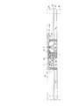
図4は、ナノプロジェクタに使用されるためのパネルの一部を概略的に示す断面図である。図3に示された要素と共通する要素は、同一の参照番号で示されており、以下に再度説明されない。図5は、図4に示されたパネルのセルを示す平面図であり、図4に示された全ての要素が図5に示されているわけではない。 FIG. 4 is a cross-sectional view schematically showing a part of a panel for use in a nanoprojector. Elements in common with those shown in FIG. 3 are indicated with the same reference numerals and will not be described again below. FIG. 5 is a plan view showing the cells of the panel shown in FIG. 4, and not all the elements shown in FIG. 4 are shown in FIG.
セル3 毎に、MOS 制御トランジスタ9 が、セル3 の隅部に設けられた、半導体層39のシリコン領域70(活性領域)に形成されている。半導体層39の残りの領域71が酸化している。図5に示されているように、4つの環状に隣り合うセル3 のMOS 制御トランジスタ9 が4つのセル3 の集合体の中央部にあるようにシリコン領域70は配置されている。
For each
各MOS 制御トランジスタ9 は、複数の金属被覆層73、例えば3つの金属被覆層75,76,77のみで覆われている。
Each
例えば銅から形成された下方の金属被覆層75及び中間の金属被覆層76は、MOS 制御トランジスタ9 のソースコンタクト、ドレインコンタクト及びゲートコンタクトの接続部分を形成するため、且つシリコン領域70を接地するために使用される。上方の金属被覆層77はセル3 に電力を供給するために使用される。
The
4つの隣り合うセル3 の集合体毎に、上方の金属被覆層77は、MOS 制御トランジスタ9 の上側に連なって設けられており、MOS 制御トランジスタに直接達する光線を遮るために光学的な遮蔽体として使用される。
For each group of four
セル3 毎に、導電性材料、例えば銅から形成されたバイア81が、MOS 制御トランジスタ9 の主電極に接続された下方の金属被覆層75の金属被覆体を上側透明電極35(第1の透明電極)に接続する。バイア81は、例えば、4つのセル3 の集合体の中心に近い位置に配置されている。
For each
MOS 制御トランジスタ9 に横方向に達し得る寄生放射を遮るために、導電性材料から形成された第1の環状体83が下方の金属被覆層75から各セル3 の上側透明電極35に延びており、第1の環状体83は、4つの隣り合うセル3 のMOS 制御トランジスタ9 を囲んでいる。
In order to block the parasitic radiation which can reach the
導電性の第1の環状体83は、各液晶セル3 のコンデンサ21と並列に配置された蓄積コンデンサ27の電極として更に使用される。
The conductive first
このために、絶縁材料から形成された環状体85(絶縁体)が、導電性の第1の環状体83と各セル3 の上側透明電極35との間に設けられている。絶縁性の環状体85は、各セル3 の蓄積コンデンサ27の誘電体を形成しており、導電性の第1の環状体83は蓄積コンデンサ27の電極の一方を形成しており、上側透明電極35は蓄積コンデンサ27の電極の他方を形成している。
For this purpose, an annular body 85 (insulator) made of an insulating material is provided between the conductive first
導電性の第1の環状体83は、図2の電気回路図に従って、全てのセル3 に共通する下側透明電極33のように接地されている。
The conductive first
導電性の第1の環状体83の幅w 、絶縁性の環状体85の厚さe 、及びそれらの特性が、蓄積コンデンサに関して所望の値を得るべく選択されている。
The width w of the conductive first
図4及び5に示されたタイプのパネルの利点は、MOS 制御トランジスタがMOS 制御トランジスタに直接達する光線から、上述したように上方の金属被覆層によって保護され、4つの隣り合うセルのMOS 制御トランジスタを囲む導電性の環状体によって横方向の寄生放射から保護されることである。 The advantages of the type of panel shown in FIGS. 4 and 5 are that the MOS control transistor is protected from light rays reaching the MOS control transistor directly by the upper metallization layer as described above, and the MOS control transistor of four adjacent cells. Is protected from lateral parasitic radiation by a conductive annulus surrounding it.
このようなパネルの別の利点は、4つの隣り合うセルのMOS 制御トランジスタを囲み、寄生放射からMOS 制御トランジスタを保護するための導電性の環状体が、各セルの蓄積コンデンサの電極を更に形成していることである。従って、MOS 制御トランジスタの隣りに各セルの蓄積コンデンサを形成する必要がなく、それ故、セルの有効表面積を減少させずにMOS 制御トランジスタは3つの金属被覆層のみで覆われ得る。 Another advantage of such a panel is that a conductive ring surrounding the MOS control transistor of four adjacent cells and protecting the MOS control transistor from parasitic radiation further forms an electrode for the storage capacitor of each cell. Is. Thus, it is not necessary to form a storage capacitor for each cell next to the MOS control transistor, and therefore the MOS control transistor can be covered with only three metallization layers without reducing the effective surface area of the cell.
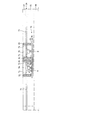
図6は、ナノプロジェクタに使用されるための別のパネルの一部を概略的に示す断面図である。 FIG. 6 is a cross-sectional view schematically showing a part of another panel for use in a nanoprojector.
4つの隣り合うセル3 のMOS 制御トランジスタ9 を囲む導電性の第1の環状体83に加えて、MOS 制御トランジスタ9 の寄生放射からの保護を更に改善すべく、導電性の第2の環状体87及び第3の環状体89が第1の環状体83の上側に配置されている。
In addition to the conductive
第2の環状体87は、中間の金属被覆層76から下方の金属被覆層75に延びている。第3の環状体89は、上方の金属被覆層77から中間の金属被覆層76に延びている。第2の環状体87及び第3の環状体89は、例えば第1の環状体83と同一の導電性材料から形成されている。
The second
図6に示されたタイプのパネルでは、4つの隣り合うセル3 のMOS 制御トランジスタ9 は、光を通さない材料で全体的に囲まれている。すなわち、MOS 制御トランジスタの上側に、連続した上方の金属被覆層77が配置されており、MOS 制御トランジスタの横方向に導電性の第1,第2及び第3の環状体83,87,89が配置されている。
In the panel of the type shown in FIG. 6, the
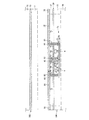
図7A乃至7Eは、図4及び5に示されたタイプのパネルを製造するための方法の連続的な工程を概略的に示す断面図である。 7A to 7E are cross-sectional views schematically illustrating successive steps of a method for manufacturing a panel of the type shown in FIGS. 4 and 5. FIG.
図7Aは、MOS 制御トランジスタ9 が形成されているSOI (シリコンオンインシュレータ)タイプの基板を概略的に示す断面図である。
FIG. 7A is a cross-sectional view schematically showing an SOI (silicon on insulator) type substrate on which the
半導体基板36、例えばシリコン基板が、例えば本分野で現在BOX (Buried OXide)と称される酸化シリコンから形成された第1の絶縁層37で覆われ、第1の絶縁層37自体は、例えば単結晶シリコンから形成された半導体層39で覆われる。半導体層39の厚さは、例えば50乃至250 nmであり、例えば約150 nmである。
A
MOS 制御トランジスタ9 が、半導体層39の活性領域70に形成される。各MOS 制御トランジスタ9 は導電性のゲート42を有し、ゲート42は、ゲート絶縁体43と、ゲート42を囲むスペーサ45と、ソース及びドレインの領域47とによって半導体層39の表面から絶縁される。各MOS 制御トランジスタ9 は、パネルのセル3 の制御トランジスタに相当する。4つの隣り合うセル3 のMOS 制御トランジスタ9 が4つのセル3 の集合体の中央部に設けられているように、MOS 制御トランジスタ9 はセル3 の隅部に形成される。活性領域70の外側で半導体層39は酸化し、このような酸化した半導体層39は、酸化シリコンから形成された透明な領域71に相当する。
A
図7Bは、形成された構造体に第2の絶縁層51を堆積した後の構造体を示している。セル3 毎に、第2の開口部79が、例えばセルの隅部の活性領域70の隣りに第2の絶縁層51の上側から半導体基板36に至るまで形成される。第2の開口部79と同時に、4つの隣り合うセル3 のMOS 制御トランジスタ9 を囲む第1の開口部82が、第2の絶縁層51の上側から半導体基板36に至るまで形成される。その後、第2の開口部79及び第1の開口部82に、導電性材料80、例えば銅が充填される。導電性材料80が充填された第2の開口部79及び第1の開口部82は夫々、半導体基板36に至るまで延びるバイア81及び第1の環状体83を形成する。
FIG. 7B shows the structure after depositing a second insulating
大きさの例として、導電性の各第1の環状体83の幅w が、例えば0.2 乃至0.3 μm であり、例えば約0.25μm である。
As an example of the size, the width w of each conductive first
図7Cは、複数の金属被覆層73、例えば3つの金属被覆層75,76,77を例えば銅からMOS 制御トランジスタ9 の上側に形成した後の構造体を示している。下方の金属被覆層75の金属被覆体がバイア81及び第1の環状体83の上に配置されている。上方の金属被覆層77は、4つの隣り合うセル3 の各集合体のMOS 制御トランジスタ9 を連続して覆うために形成されている。
FIG. 7C shows the structure after a plurality of metal cover layers 73, for example, three metal cover layers 75, 76, 77 are formed on the upper side of the
図7Dは、金属被覆層73を支持する構造体を例えばガラスから形成された第1の透明板54に結合し、半導体基板36を除去した後の構造体を示している。そのため、導電性の第1の環状体83が第1の絶縁層37の面から露出している。
FIG. 7D shows the structure after the structure supporting the
図7Eは、導電性の第1の環状体83の見えている面の上に絶縁材料から形成された環状体85が形成されている構造体を示している。絶縁性の環状体85は、例えば酸化シリコン又は高誘電率の材料から形成される。絶縁性の環状体85の厚さe は、例えば1乃至5nmであり、例えば約2nmである。その後、セル3 毎に、第1の透明電極35(上側透明電極)が第1の絶縁層37及び絶縁性の環状体85の上に形成される。このようにしてプレート100 が得られる。
FIG. 7E shows a structure in which an
例えばガラスから形成された第2の透明板32上に第2の透明電極33(下側透明電極)が形成され、プレート102 が形成される。
For example, the second transparent electrode 33 (lower transparent electrode) is formed on the second
その後、プレート100 及びプレート102 は互いに対向して置かれ、スペーサが配置され、液晶層7 がプレート100 及びプレート102 間に挿入される。その結果、図4に示されたタイプの構造体が得られる。
Thereafter, the
第2の透明電極33及び第1の透明電極35は、例えばITO (インジウム酸化錫)から形成されている。
The second
図6に示されたタイプのパネルを形成するために、導電性の第2及び第3の環状体87,89 が、上述されたタイプの方法の図7Cに示された金属被覆層形成工程で形成される。
In order to form a panel of the type shown in FIG. 6, conductive second and third
下方の金属被覆層75を形成した後に、導電性の第2の環状体87が導電性の第1の環状体83の上側に形成される。中間の金属被覆層76を形成した後に、導電性の第3の環状体89が導電性の第2の環状体87の上側に形成される。
After forming the lower
本発明の具体的な実施形態が記述されているが、様々な変更、修正及び改良が当業者に容易に想起される。 While specific embodiments of the present invention have been described, various changes, modifications and improvements will readily occur to those skilled in the art.
特に、酸化シリコンから形成された第1の絶縁層37を備えたパネルが記述されているが、第1の絶縁層37は、他のあらゆる透明な絶縁材料から形成されてもよい。
In particular, although a panel is described that includes a first insulating
酸化シリコンから形成された半導体層39の残りの領域71が記述されているが、残りの領域71は他のあらゆる透明な絶縁材料から形成されてもよい。
Although the remaining
導電性の第1の環状体83が導電性材料から形成されていると記述されているが、第1の環状体83は、異なる導電性材料から形成された複数の層を有してもよい。導電性の第2及び第3の環状体87,89 についても同様である。
Although the conductive first
3 セル
7 液晶層
9 MOS 制御トランジスタ
32 第2の透明板
33 下側透明電極,第2の透明電極
35 上側透明電極,第1の透明電極
36 半導体基板
37 第1の絶縁層
39 半導体層
51 第2の絶縁層
54 第1の透明板
70 活性領域
71 残りの領域
75,76,77 金属被覆層
79 第2の開口部
80 導電性材料
81 バイア
82 第1の開口部
83 第1の環状体
85 絶縁体
87 第2の環状体
89 第3の環状体
3 cells
7 Liquid crystal layer
9 MOS control transistor
32 Second transparent plate
33 Lower transparent electrode, second transparent electrode
35 Upper transparent electrode, first transparent electrode
36 Semiconductor substrate
37 First insulation layer
39 Semiconductor layer
51 Second insulation layer
54 First transparent plate
70 Active region
71 remaining area
75,76,77 Metal coating layer
79 Second opening
80 Conductive material
81 Bahia
82 First opening
83 1st ring
85 Insulator
87 Second annulus
89 Third ring
Claims (8)
各セルは、上側透明電極及び下側透明電極に囲まれた液晶層を有しており、前記上側透明電極の上側にMOS 制御トランジスタが配置されており、該MOS 制御トランジスタは、少なくとも3つの金属被覆層で覆われており、
4つの隣り合う前記セルの集合体のMOS 制御トランジスタが前記集合体の中央部に配置されているように、各セルのMOS 制御トランジスタは前記セルの隅部に設けられており、
上方の前記金属被覆層は、前記4つの隣り合うセルの集合体のMOS 制御トランジスタの上側を覆っており、
前記パネルは、前記4つの隣り合うセルの集合体毎に、前記MOS 制御トランジスタを囲む導電性の第1の環状体を備えており、該第1の環状体は、下方の前記金属被覆層から絶縁体を介して各セルの前記上側透明電極に延びていることを特徴とするパネル。 A panel formed from an array of cells for use in a nanoprojector,
Each cell has a liquid crystal layer surrounded by an upper transparent electrode and a lower transparent electrode, and a MOS control transistor is disposed above the upper transparent electrode, and the MOS control transistor includes at least three metal electrodes. Covered with a coating layer,
The MOS control transistor of each cell is provided at the corner of the cell so that the MOS control transistor of the assembly of four adjacent cells is disposed in the center of the assembly.
The upper metal coating layer covers the upper side of the MOS control transistor of the assembly of the four adjacent cells,
The panel includes, for each of the four adjacent cell assemblies, a conductive first annular body surrounding the MOS control transistor, and the first annular body is formed from the lower metal coating layer. A panel extending to the upper transparent electrode of each cell via an insulator.
前記第2の環状体は、中間の前記金属被覆層から前記下方の金属被覆層に延びており、
前記第3の環状体は、前記上方の金属被覆層から前記中間の金属被覆層に延びていることを特徴とする請求項1に記載のパネル。 A conductive second annular body and a conductive third annular body, which surround the MOS control transistor and are provided on the upper side of the first annular body for each of the four adjacent cell assemblies, are further provided. With
The second annular body extends from the intermediate metal coating layer to the lower metal coating layer,
The panel according to claim 1, wherein the third annular body extends from the upper metal coating layer to the intermediate metal coating layer.
半導体層で覆われた第1の絶縁層によって覆われた半導体基板を備えたウエハを準備する工程と、
4つの隣り合うセル夫々のMOS 制御トランジスタが前記4つの隣り合うセルの集合体の中央部に配置されるように、各セルの隅部であって前記半導体層の活性領域に各セルのMOS 制御トランジスタを形成し、前記半導体層の残りの領域を酸化させる工程と、
形成された構造体に第2の絶縁層を堆積させ、前記4つの隣り合うセルの集合体のMOS 制御トランジスタを囲む第1の開口部を前記第2の絶縁層の上側から前記半導体基板に至るまで形成する工程と、
前記第1の開口部に導電性材料を充填して導電性の第1の環状体を形成する工程と、
各MOS 制御トランジスタの上側に少なくとも3つの金属被覆層を形成して、下方の前記金属被覆層の金属被覆体を前記第1の環状体上に形成し、上方の前記金属被覆層を、前記4つの隣り合うセルの集合体のMOS 制御トランジスタを連続して覆うように形成する工程と、
前記金属被覆層を支持する構造体の表面を第1の透明板に結合し、前記半導体基板を除去して前記第1の環状体を露出させる工程と、
各第1の環状体上に絶縁体を形成する工程と、
前記セル毎に、前記第1の絶縁層及び前記絶縁体を第1の透明電極で覆う工程と、
第2の透明電極を第2の透明板上に形成する工程と、
前記第1及び第2の透明板を組み立てて、前記第1の透明電極及び第2の透明電極を、液晶層を介して互いに対向させる工程と
を有することを特徴とする方法。 A method for manufacturing a panel formed from an array of cells and used for a nanoprojector comprising:
Preparing a wafer comprising a semiconductor substrate covered by a first insulating layer covered by a semiconductor layer;
MOS control of each cell is placed in the active region of the semiconductor layer at the corner of each cell so that the MOS control transistors of each of the four adjacent cells are arranged in the center of the assembly of the four adjacent cells. Forming a transistor and oxidizing the remaining region of the semiconductor layer;
A second insulating layer is deposited on the formed structure, and a first opening surrounding the MOS control transistor of the assembly of the four adjacent cells extends from the upper side of the second insulating layer to the semiconductor substrate. A process of forming until
Filling the first opening with a conductive material to form a conductive first annular body;
At least three metal coating layers are formed on the upper side of each MOS control transistor, and a metal coating body of the lower metal coating layer is formed on the first annular body. Forming a MOS control transistor of a group of two adjacent cells so as to continuously cover;
Bonding the surface of the structure supporting the metal coating layer to a first transparent plate, removing the semiconductor substrate and exposing the first annular body;
Forming an insulator on each first annular body;
Covering the first insulating layer and the insulator with a first transparent electrode for each cell;
Forming a second transparent electrode on the second transparent plate;
Assembling the first and second transparent plates, and causing the first transparent electrode and the second transparent electrode to face each other through a liquid crystal layer.
前記第1の環状体の上側に中間の前記金属被覆層から前記下方の金属被覆層に導電性の第2の環状体を形成する工程と、
前記第2の環状体の上側に上方の前記金属被覆層から前記中間の金属被覆層に導電性の第3の環状体を形成する工程と
を更に有することを特徴とする請求項6に記載の方法。 In the step of forming the metal coating layer on the upper side of each MOS control transistor,
Forming a conductive second annular body on the upper side of the first annular body from the intermediate metal coating layer to the lower metal coating layer;
The method further comprises: forming a conductive third annular body on the intermediate metallic coating layer from the upper metallic coating layer on the upper side of the second annular body. Method.
前記第1の開口部に充填する工程では、前記第2の開口部に前記導電性材料を更に充填してバイアを形成し、
前記金属被覆層を形成する工程では、前記下方の金属被覆層の金属被覆体を前記バイアの上に形成することを特徴とする請求項6又は7に記載の方法。 In the step of forming the first opening surrounding the MOS control transistor of the assembly of the four adjacent cells, a second opening is further formed from the upper side of the second insulating layer to the semiconductor substrate. And
In the step of filling the first opening, a via is formed by further filling the second opening with the conductive material;
The method according to claim 6 or 7, wherein, in the step of forming the metal cover layer, a metal cover of the lower metal cover layer is formed on the via.
Applications Claiming Priority (2)
| Application Number | Priority Date | Filing Date | Title |
|---|---|---|---|
| FR1255732 | 2012-06-19 | ||
| FR1255732A FR2992096A1 (en) | 2012-06-19 | 2012-06-19 | PANEL COMPRISING A LIQUID CRYSTAL CELL MATRIX FOR USE IN A NANOPROJECTOR |
Publications (2)
| Publication Number | Publication Date |
|---|---|
| JP2014002382A true JP2014002382A (en) | 2014-01-09 |
| JP6178634B2 JP6178634B2 (en) | 2017-08-09 |
Family
ID=48578962
Family Applications (1)
| Application Number | Title | Priority Date | Filing Date |
|---|---|---|---|
| JP2013124906A Active JP6178634B2 (en) | 2012-06-19 | 2013-06-13 | Nano-projector panel formed from aligned liquid crystal cells |
Country Status (4)
| Country | Link |
|---|---|
| US (1) | US9052560B2 (en) |
| EP (1) | EP2677361B1 (en) |
| JP (1) | JP6178634B2 (en) |
| FR (1) | FR2992096A1 (en) |
Families Citing this family (1)
| Publication number | Priority date | Publication date | Assignee | Title |
|---|---|---|---|---|
| CN104269410A (en) * | 2014-09-03 | 2015-01-07 | 合肥京东方光电科技有限公司 | Array substrate and display device |
Citations (10)
| Publication number | Priority date | Publication date | Assignee | Title |
|---|---|---|---|---|
| JPH0456827A (en) * | 1990-06-25 | 1992-02-24 | Fujitsu Ltd | Reflection type liquid crystal panel |
| JPH05257171A (en) * | 1991-12-02 | 1993-10-08 | Canon Inc | Image display device and its production |
| JPH10123569A (en) * | 1996-10-22 | 1998-05-15 | Seiko Epson Corp | Substrate for liquid crystal panel, liquid crystal panel, electronic apparatus and reflection type display device |
| JP2000098409A (en) * | 1998-09-24 | 2000-04-07 | Seiko Epson Corp | Electrooptical device and its manufacture, and electronic equipment |
| JP2004264463A (en) * | 2003-02-14 | 2004-09-24 | Seiu Kagi Kofun Yugenkoshi | Liquid crystal display panel and method for manufacturing the same |
| JP2008040399A (en) * | 2006-08-10 | 2008-02-21 | Seiko Epson Corp | Substrate for electrooptical device, electrooptical device, and electronic apparatus |
| US20080129911A1 (en) * | 2006-12-04 | 2008-06-05 | Semiconductor Manufacturing International (Shanghai) Corporation | Lcos display unit and method for forming the same |
| JP2008292538A (en) * | 2007-05-22 | 2008-12-04 | Seiko Epson Corp | Reflection type electrooptical device and projection display device |
| JP2010204600A (en) * | 2009-03-06 | 2010-09-16 | Seiko Epson Corp | Electrooptical device and manufacturing method therefor |
| US20100283926A1 (en) * | 2008-07-03 | 2010-11-11 | Seiconductor Manufacturing International (Shanghai) Corporation | Method and resulting capacitor structure for liquid crystal on silicon display devices |
Family Cites Families (7)
| Publication number | Priority date | Publication date | Assignee | Title |
|---|---|---|---|---|
| US5402254B1 (en) * | 1990-10-17 | 1998-09-22 | Hitachi Ltd | Liquid crystal display device with tfts in which pixel electrodes are formed in the same plane as the gate electrodes with anodized oxide films before the deposition of silicon |
| US5705424A (en) * | 1992-09-11 | 1998-01-06 | Kopin Corporation | Process of fabricating active matrix pixel electrodes |
| JPH06265932A (en) * | 1993-03-12 | 1994-09-22 | Fujitsu General Ltd | Liquid crystal panel for projection projector |
| US6452652B1 (en) * | 1998-06-12 | 2002-09-17 | National Semiconductor Corporation | Light absorbing thin film stack in a light valve structure |
| KR20040091299A (en) * | 2003-04-21 | 2004-10-28 | 일진다이아몬드(주) | Liquid crystal display panel and liquid crystal projector with an improved transmittance |
| KR200400912Y1 (en) | 2004-08-11 | 2005-11-09 | 인터디지탈 테크날러지 코포레이션 | Channel sounding for improved system performance |
| FR2965942B1 (en) * | 2010-10-08 | 2013-02-22 | Commissariat Energie Atomique | LIQUID CRYSTAL DISPLAY OF TRANSMISSIVE TYPE IN CMOS TECHNOLOGY WITH AUXILIARY STORAGE CAPACITY |
-
2012
- 2012-06-19 FR FR1255732A patent/FR2992096A1/en active Pending
-
2013
- 2013-06-13 JP JP2013124906A patent/JP6178634B2/en active Active
- 2013-06-17 EP EP13172292.8A patent/EP2677361B1/en active Active
- 2013-06-18 US US13/920,206 patent/US9052560B2/en active Active
Patent Citations (10)
| Publication number | Priority date | Publication date | Assignee | Title |
|---|---|---|---|---|
| JPH0456827A (en) * | 1990-06-25 | 1992-02-24 | Fujitsu Ltd | Reflection type liquid crystal panel |
| JPH05257171A (en) * | 1991-12-02 | 1993-10-08 | Canon Inc | Image display device and its production |
| JPH10123569A (en) * | 1996-10-22 | 1998-05-15 | Seiko Epson Corp | Substrate for liquid crystal panel, liquid crystal panel, electronic apparatus and reflection type display device |
| JP2000098409A (en) * | 1998-09-24 | 2000-04-07 | Seiko Epson Corp | Electrooptical device and its manufacture, and electronic equipment |
| JP2004264463A (en) * | 2003-02-14 | 2004-09-24 | Seiu Kagi Kofun Yugenkoshi | Liquid crystal display panel and method for manufacturing the same |
| JP2008040399A (en) * | 2006-08-10 | 2008-02-21 | Seiko Epson Corp | Substrate for electrooptical device, electrooptical device, and electronic apparatus |
| US20080129911A1 (en) * | 2006-12-04 | 2008-06-05 | Semiconductor Manufacturing International (Shanghai) Corporation | Lcos display unit and method for forming the same |
| JP2008292538A (en) * | 2007-05-22 | 2008-12-04 | Seiko Epson Corp | Reflection type electrooptical device and projection display device |
| US20100283926A1 (en) * | 2008-07-03 | 2010-11-11 | Seiconductor Manufacturing International (Shanghai) Corporation | Method and resulting capacitor structure for liquid crystal on silicon display devices |
| JP2010204600A (en) * | 2009-03-06 | 2010-09-16 | Seiko Epson Corp | Electrooptical device and manufacturing method therefor |
Also Published As
| Publication number | Publication date |
|---|---|
| EP2677361A1 (en) | 2013-12-25 |
| US20130335666A1 (en) | 2013-12-19 |
| FR2992096A1 (en) | 2013-12-20 |
| EP2677361B1 (en) | 2015-08-05 |
| JP6178634B2 (en) | 2017-08-09 |
| US9052560B2 (en) | 2015-06-09 |
Similar Documents
| Publication | Publication Date | Title |
|---|---|---|
| EP0582850B1 (en) | Digital micromirror | |
| JP4472961B2 (en) | Display device substrate, liquid crystal display device, and method of manufacturing liquid crystal display device | |
| JPS6045219A (en) | Active matrix type display device | |
| KR20180076661A (en) | Substrate for display and display including the same | |
| CN101625491A (en) | Liquid crystal display device and method for fabricating the same | |
| WO2013075505A1 (en) | Tft array substrate and forming method thereof, and display panel | |
| JP2012027163A (en) | Electrophoretic display device | |
| TW201013279A (en) | Liquid crystal display and method of manufacturing the same | |
| US20070023752A1 (en) | Transistor array panel, liquid crystal display panel, and method of manufacturing liquid crystal display panel | |
| JP2010256517A (en) | Active matrix display device | |
| WO2018209761A1 (en) | Array substrate, method for manufacturing same, and liquid crystal display panel | |
| KR20010082161A (en) | Liquid crystal display panel and fabrication method of the same | |
| KR20180087304A (en) | Array substrate used in liquid crystal panel and manufacturing method thereof | |
| WO2019233113A1 (en) | Array substrate and display device | |
| CN101350330A (en) | Thin-film transistor array substrate and manufacturing method thereof | |
| TWI335483B (en) | Pixel structure and liquid crystal display panel | |
| JP2018194640A (en) | Liquid crystal display device | |
| CN109828395A (en) | A kind of array substrate and its manufacturing method | |
| KR20040055688A (en) | Manufacturing method for electrooptical substrate, electrooptical apparatus, and manufacturing method for same | |
| JPH10142636A (en) | Active matrix type display circuit | |
| JP6178634B2 (en) | Nano-projector panel formed from aligned liquid crystal cells | |
| KR102042530B1 (en) | Thin film transistor array substrate and method of fabricating the same | |
| KR20140031191A (en) | Tft array substrate and forming method thereof, and display panel | |
| JPH1010581A (en) | Display device | |
| CN100520542C (en) | Method for fabricating LCD and baseplate of thin film transistor |
Legal Events
| Date | Code | Title | Description |
|---|---|---|---|
| A621 | Written request for application examination |
Free format text: JAPANESE INTERMEDIATE CODE: A621 Effective date: 20160511 |
|
| A977 | Report on retrieval |
Free format text: JAPANESE INTERMEDIATE CODE: A971007 Effective date: 20170317 |
|
| A131 | Notification of reasons for refusal |
Free format text: JAPANESE INTERMEDIATE CODE: A131 Effective date: 20170328 |
|
| A521 | Request for written amendment filed |
Free format text: JAPANESE INTERMEDIATE CODE: A523 Effective date: 20170606 |
|
| TRDD | Decision of grant or rejection written | ||
| A01 | Written decision to grant a patent or to grant a registration (utility model) |
Free format text: JAPANESE INTERMEDIATE CODE: A01 Effective date: 20170704 |
|
| A61 | First payment of annual fees (during grant procedure) |
Free format text: JAPANESE INTERMEDIATE CODE: A61 Effective date: 20170714 |
|
| R150 | Certificate of patent or registration of utility model |
Ref document number: 6178634 Country of ref document: JP Free format text: JAPANESE INTERMEDIATE CODE: R150 |
|
| R250 | Receipt of annual fees |
Free format text: JAPANESE INTERMEDIATE CODE: R250 |
|
| R250 | Receipt of annual fees |
Free format text: JAPANESE INTERMEDIATE CODE: R250 |
|
| R250 | Receipt of annual fees |
Free format text: JAPANESE INTERMEDIATE CODE: R250 |
|
| R250 | Receipt of annual fees |
Free format text: JAPANESE INTERMEDIATE CODE: R250 |