JP2013536660A - Wireless remote control by position sensor system - Google Patents
Wireless remote control by position sensor system Download PDFInfo
- Publication number
- JP2013536660A JP2013536660A JP2013526321A JP2013526321A JP2013536660A JP 2013536660 A JP2013536660 A JP 2013536660A JP 2013526321 A JP2013526321 A JP 2013526321A JP 2013526321 A JP2013526321 A JP 2013526321A JP 2013536660 A JP2013536660 A JP 2013536660A
- Authority
- JP
- Japan
- Prior art keywords
- machine
- wireless remote
- motion
- handheld unit
- control system
- Prior art date
- Legal status (The legal status is an assumption and is not a legal conclusion. Google has not performed a legal analysis and makes no representation as to the accuracy of the status listed.)
- Pending
Links
Images


Classifications
-
- G—PHYSICS
- G08—SIGNALLING
- G08C—TRANSMISSION SYSTEMS FOR MEASURED VALUES, CONTROL OR SIMILAR SIGNALS
- G08C17/00—Arrangements for transmitting signals characterised by the use of a wireless electrical link
- G08C17/02—Arrangements for transmitting signals characterised by the use of a wireless electrical link using a radio link
-
- G—PHYSICS
- G08—SIGNALLING
- G08C—TRANSMISSION SYSTEMS FOR MEASURED VALUES, CONTROL OR SIMILAR SIGNALS
- G08C2201/00—Transmission systems of control signals via wireless link
- G08C2201/30—User interface
- G08C2201/32—Remote control based on movements, attitude of remote control device
-
- G—PHYSICS
- G08—SIGNALLING
- G08C—TRANSMISSION SYSTEMS FOR MEASURED VALUES, CONTROL OR SIMILAR SIGNALS
- G08C2201/00—Transmission systems of control signals via wireless link
- G08C2201/50—Receiving or transmitting feedback, e.g. replies, status updates, acknowledgements, from the controlled devices
Abstract
本発明は、制御ユニット、送信デバイス、および少なくとも1つの動きセンサを有するハンドヘルドデバイス(10)を含む、無線遠隔制御によって作動することができる、移動可能なマシン部分のための少なくとも1つのマシン駆動装置を有するマシンの無線遠隔制御に関し、制御ユニットは、ユーザによってもたらされる制御コマンドを送信デバイスに送信し、送信デバイスに、制御コマンドをマシンに、特に関連する受信デバイスに送信させるように構成され、少なくとも1つの傾斜軸または傾き軸(KA、DA)の周りの空中におけるハンドヘルドデバイス(10)の動きを動きセンサによって感知することができ、したがって、動き操作モードにおいて、感知された動きを、制御ユニットによってマシンに送信することができる制御コマンドに変換することができ、動き操作モードを、ハンドヘルドデバイス(10)でのユーザ側の入力の後、起動することができる。本発明によれば、制御ユニットは、動き操作モードが起動されると、空中におけるハンドヘルドデバイス(10)の現在の位置(I)が現在の基準位置(I)として感知され、その結果、この現在の基準位置(I)に対する動きを動きセンサによって感知することができ、制御コマンドとして制御ユニットによってマシンに送信することができるようにも構成されることが提案される。さらに、本発明は、本発明による無線遠隔制御のための操作方法に関する。 The present invention provides at least one machine drive for a movable machine part that can be operated by wireless remote control, including a control unit, a transmission device, and a handheld device (10) having at least one motion sensor The control unit is configured to transmit a control command provided by a user to a transmitting device, causing the transmitting device to transmit a control command to the machine, particularly to an associated receiving device, and at least The movement of the handheld device (10) in the air around one tilt axis or tilt axis (KA, DA) can be sensed by the motion sensor, so in the motion operating mode, the sensed motion can be sensed by the control unit. To control commands that can be sent to the machine Can be, movement operating mode, after the user-side input of a handheld device (10) can be activated. According to the present invention, when the motion operation mode is activated, the control unit senses the current position (I) of the handheld device (10) in the air as the current reference position (I), and as a result, It is proposed that the movement relative to the reference position (I) can be sensed by a motion sensor and can also be transmitted as a control command to the machine by a control unit. Furthermore, the present invention relates to an operating method for wireless remote control according to the present invention.
Description
本発明は、移動可能なマシン部分のための少なくとも1つのマシン駆動装置を含むマシンの無線遠隔制御システムに関し、無線遠隔制御システムによってマシン駆動装置を制御することができ、無線遠隔制御システムは、マシンに割り当てられた無線受信機と、制御ユニット、送信機、および少なくとも1つの動きセンサを含むハンドヘルドユニットとを含み、制御ユニットは、ユーザによって発行された制御コマンドを送信機に通信し、送信機に、制御コマンドを受信機に送信させるように構成され、動き制御モードにおいて、検出された動きを、制御ユニットによって、送信機と受信機との間の無線送信によってマシンに通信することができる制御コマンドに変換することができるよう、少なくとも1つの傾斜軸またはピッチ軸(KA、DA)の周りの空中におけるハンドヘルドユニットの動きを動きセンサによって検出することができ、動き制御モードは、ハンドヘルドユニットでのユーザ入力によって起動することができる。 The present invention relates to a wireless remote control system for a machine including at least one machine drive for a movable machine part, the machine drive can be controlled by the wireless remote control system, And a control unit, a transmitter, and a handheld unit including at least one motion sensor, wherein the control unit communicates a control command issued by a user to the transmitter and A control command configured to cause a control command to be transmitted to the receiver, and in motion control mode, the detected motion can be communicated by the control unit to the machine by wireless transmission between the transmitter and the receiver Around at least one tilt axis or pitch axis (KA, DA) so that it can be converted to Can be detected by the motion sensor a movement of the handheld unit in the air, the motion control mode can be activated by a user input at the hand-held unit.
本発明の排他的な用途ではないが特に好ましい用途は、クレーンおよび吊り上げ装置の制御である。ジブクレーン、たとえば建設用クレーンの例では、本発明に従って適切に設計された無線遠隔制御システムを使用して、たとえばジブの向き(回転角)、トロリーの動き、およびフックの動きを制御することが可能である。 A particularly preferred but not exclusive application of the present invention is the control of cranes and lifting equipment. In the case of jib cranes, e.g. construction cranes, it is possible to control e.g. jib orientation (rotation angle), trolley movement, and hook movement using a wireless remote control system appropriately designed according to the present invention It is.
リモートコントローラまたはリモートコントローラと類似の構成要素における姿勢センサによって機器を制御することが知られている。例として、ゲーム機などを参照する。今日、姿勢センサは、たとえば、携帯電話にも取り付けられており、デバイスの向きに対して、ディスプレイに表示されるものを調整するために、そのようなデバイスの向き、特に、デバイスディスプレイの向きを決定することが可能である。 It is known to control a device by a posture sensor in a remote controller or a component similar to the remote controller. For example, a game machine is referred to. Today, attitude sensors are also attached to mobile phones, for example, to adjust the orientation of such devices, in particular the orientation of the device display, in order to adjust what is displayed on the display relative to the orientation of the device. It is possible to determine.
マシンのための無線遠隔制御システムを最適に利用できるようにするために、空中におけるハンドヘルドユニットの動きを正確に検出できることが必要である。また、無線遠隔制御システムは、特に、ユーザがハンドヘルドユニットを動かすことによってマシンを操作しようとする場合、ハンドヘルドユニットによってユーザに直観的であるマシン制御を可能にすることも確実にしなければならない。 In order to be able to optimally use a wireless remote control system for a machine, it is necessary to be able to accurately detect the movement of the handheld unit in the air. The wireless remote control system must also ensure that the handheld unit allows machine control that is intuitive to the user, especially when the user intends to operate the machine by moving the handheld unit.
本発明の目的は、ユーザによる直観的な操作に関して当該のタイプの無線遠隔制御システムを改善することである。 The object of the present invention is to improve this type of wireless remote control system with regard to intuitive operation by the user.
この目的のために、第1の態様によれば、制御ユニットは、動き制御モードを起動させると、空中におけるハンドヘルドユニットの現在の姿勢が現在の基準姿勢として検出され、その結果、この現在の基準姿勢に対する動きを動きセンサによって検出することができ、制御コマンドとして制御ユニットによってマシンに通信することができるように構成されることが提案される。 For this purpose, according to the first aspect, when the control unit activates the motion control mode, the current attitude of the handheld unit in the air is detected as the current reference attitude, so that this current reference It is proposed that the movement with respect to the posture can be detected by a motion sensor and configured to be communicated to the machine by a control unit as a control command.
制御ユニットのそのような一実施形態では、ユーザにとって快適である手の位置で現在の基準姿勢を決定することが可能である。無線遠隔制御システムのハンドヘルドユニットは、必ずしも正確に水平に保たれないことが多いが、人の手の自然なポーズによって、ハンドヘルドユニットは、わずかに上方に傾いて保持される。次いで、この自然なポーズを、現在の基準姿勢、言い換えれば、一種の中立位置として決定することができ、その結果、動きセンサによって検出された動き、たとえば、ハンドヘルドユニットの回転、縦揺れ、または傾斜などの動きを検出し、制御コマンドに変換することができる。人の手のそのような自然な位置から開始することによって、適切なマシン駆動装置を制御するために、ユーザが行う可能性のある動きを最適に利用することにもなる。 In such an embodiment of the control unit, it is possible to determine the current reference posture at a hand position that is comfortable for the user. The handheld unit of a wireless remote control system is often not always kept exactly level, but due to the natural pose of the human hand, the handheld unit is held slightly tilted upward. This natural pose can then be determined as the current reference posture, in other words a kind of neutral position, so that the movement detected by the motion sensor, for example, rotation, pitching or tilting of the handheld unit Can be detected and converted into control commands. Starting from such a natural position of the human hand also optimally utilizes the user's possible movements to control the appropriate machine drive.
本発明の第2の態様によれば、無線遠隔制御システムは、動き制御モードを起動させると、空中におけるハンドヘルドユニットの現在の姿勢が検出されて、所定の基準姿勢と比較されるように、さらに無線遠隔制御システムが少なくとも所定の基準姿勢にほぼ近くなるまでは、検出された動きを制御コマンドとしてマシンに通信することができず、所定の基準姿勢に対する動きが制御コマンドを生成するために検出されるように構成されることが提案される。 According to the second aspect of the present invention, when the wireless remote control system activates the motion control mode, the current attitude of the handheld unit in the air is detected and compared with a predetermined reference attitude. Until the wireless remote control system is at least close to a predetermined reference attitude, the detected movement cannot be communicated to the machine as a control command, and movement relative to the predetermined reference attitude is detected to generate the control command. It is proposed to be configured as such.
所定の基準姿勢は、たとえば、空中におけるハンドヘルドユニットの実質的に水平な向きでよい。動き制御システムが起動する、空中におけるハンドヘルドユニットの姿勢から、この所定の基準姿勢に達するか、またはこの所定の基準姿勢をとらなければならない。ハンドヘルドユニットが所定の基準姿勢にほぼ対応する現在の姿勢になるとすぐに、または動き制御システムを起動させると、すでに現在の姿勢になっている、すなわち、この所定の基準姿勢が許容範囲内にあるとすぐに、所定の基準姿勢からはずれるハンドヘルドユニットのさらなる動きが検出され、マシンに通信することができる制御コマンドに変換される。 The predetermined reference posture may be, for example, a substantially horizontal orientation of the handheld unit in the air. This predetermined reference attitude must be reached or taken from the attitude of the handheld unit in the air when the motion control system is activated. As soon as the handheld unit is in a current position that roughly corresponds to a predetermined reference position, or when the motion control system is activated, it is already in the current position, i.e. this predetermined reference position is within an acceptable range. As soon as further movements of the handheld unit deviating from the predetermined reference position are detected and converted into control commands that can be communicated to the machine.
本発明の上述の態様は両方とも、動きセンサ、および検出された動きを制御コマンドとしてマシンに通信することを可能にする制御ユニットを含むハンドヘルドユニットによって、マシンの直観的な操作および制御を可能にする。 Both of the above aspects of the present invention allow intuitive operation and control of the machine by a handheld unit including a motion sensor and a control unit that allows the detected movement to be communicated to the machine as a control command. To do.
これに関して、本発明による無線遠隔制御システムの関連する実施形態において実施することができる2つの異なる制御システムの操作オプションを参照されたい。第1の制御システムの操作モードでは、スイッチを操作することによって、動き制御モードが起動する。これは、好ましくは、マシンに存在し得る安全関連のリレーなどを有効にし、次いで、上述した参照オプションのうちの1つに従って、ハンドヘルドユニットが参照される。次いで、検出された基準姿勢に対してハンドヘルドユニットを動かすことによって、マシン部分の制御される動きが定義され、基準姿勢に対するハンドヘルドユニットの反対方向の動きが、マシン部分をやはり対応して反対方向に移動させる制御コマンドを生成することができる。制御される動きの大きさ、したがって、たとえば、速度の大きさまたは加速度の大きさは、基準姿勢に対するハンドヘルドユニットの動きの振幅によって定義することもできる。この一例を挙げると、たとえば、動き制御モードが有効になったときに検出された基準姿勢に対してたとえば+/-30°にハンドヘルドユニットを横揺れさせることによって、マシン部分の制御される動きの方向および大きさの両方が定義され、この場合、正の範囲は、動きの一方向を表し、負の範囲は、マシン部分の動きの反対方向を表す。 In this regard, reference is made to two different control system operating options that can be implemented in related embodiments of the wireless remote control system according to the present invention. In the operation mode of the first control system, the motion control mode is activated by operating the switch. This preferably enables a safety-related relay or the like that may be present in the machine, and then the handheld unit is referenced according to one of the reference options described above. Then, the controlled movement of the machine part is defined by moving the handheld unit relative to the detected reference attitude, and the opposite movement of the handheld unit relative to the reference attitude is also correspondingly opposite to the machine part. A control command to be moved can be generated. The magnitude of the movement to be controlled, and thus, for example, the magnitude of the velocity or the acceleration, can also be defined by the amplitude of the movement of the handheld unit relative to the reference posture. An example of this is the controlled movement of the machine part, for example by rolling the handheld unit to +/- 30 °, for example +/- 30 ° with respect to the reference position detected when the motion control mode is activated. Both direction and magnitude are defined, where the positive range represents one direction of motion and the negative range represents the opposite direction of motion of the machine part.
第2の制御システムの操作モードでは、たとえば、動き制御モードを起動させるために作動しなければならない2つの接触点すなわち押しボタンが設けられ、ボタンのうちの1つは、マシン部分の一方向の動きに割り当てられ、もう1つのボタンは、マシン部分の反対方向の動きに割り当てられている。次いで、関連する基準姿勢に対するハンドヘルドユニットの動きは、たとえば、マシン部分の制御される速度の大きさのみを定義することになる。 In the operating mode of the second control system, for example, there are two contact points or push buttons that must be activated to activate the motion control mode, one of the buttons being one-way in the machine part. The other button is assigned to the movement in the opposite direction of the machine part. Then, the movement of the handheld unit relative to the relevant reference posture will, for example, only define the magnitude of the controlled speed of the machine part.
ユーザ入力のために、ハンドヘルドユニットに、たとえば、モーメンタリ動作押しボタンスイッチ(Momentary-action pushbutton switch)を設けることができる。したがって、本発明の一実施形態によれば、動き制御モードは、ハンドヘルドユニット上のスイッチを作動させることによって、開始され、マシン部分の動きを制御することができるように、このスイッチに継続的に触れることによって維持されなければならない。次いで、このスイッチを解除することによって、マシン部分の動きを制御するための制御コマンドがこれ以上送信されなくなる。したがって、これは、一種のデッドマンスイッチ(dead-man's switch)である。 For user input, the handheld unit may be provided with, for example, a momentary-action pushbutton switch. Thus, according to one embodiment of the present invention, the motion control mode is initiated by activating a switch on the handheld unit and is continuously applied to this switch so that the motion of the machine part can be controlled. Must be maintained by touching. Then, by releasing this switch, no more control commands for controlling the movement of the machine part are transmitted. This is therefore a kind of dead-man's switch.
本発明の異なる一実施形態によれば、ユーザ入力のために、ハンドヘルドユニットにラッチ型スイッチが設けられており、それによって、ユーザは、そのようなラッチ型スイッチにおけるアクティブな切替操作によって動き制御モードを起動させることができる。 According to a different embodiment of the present invention, a latch-type switch is provided in the handheld unit for user input, whereby the user can control the motion control mode by an active switching operation on such a latch-type switch. Can be activated.
無線遠隔制御システムがハンドヘルドユニットに割り当てられた少なくとも1つの出力手段を含むことが開発として提案され、前記出力手段が、ハンドヘルドユニットで、検出された動きに応答して、ユーザが知覚可能な少なくとも1つの出力、具体的には光学および/または音響および/または触覚信号を生成するように構成される。 It has been proposed as a development that the wireless remote control system includes at least one output means assigned to the handheld unit, the output means being at least one perceivable by the user in response to the detected movement at the handheld unit. It is configured to generate two outputs, specifically optical and / or acoustic and / or haptic signals.
ハンドヘルドユニットのユーザが知覚可能な出力は、マシンの直観的な、遠隔で制御される操作を改善する。特に音響および/または触覚信号は、ハンドヘルドユニットの動きによってマシンを操作することに関する直観的な方法で、ユーザを助けることができる。ヒューマンマシンインタフェースを最適化することができるように、出力は、ユーザに対するある形態のフィードバックを実行する。 The output perceivable by the user of the handheld unit improves the machine's intuitive, remotely controlled operation. In particular, the acoustic and / or tactile signals can assist the user in an intuitive way related to operating the machine by movement of the handheld unit. The output performs some form of feedback to the user so that the human machine interface can be optimized.
この目的のために、ユーザが知覚可能な出力が動きセンサによって出力された信号に基づいて生成されるように、出力手段が構成されることが特に提案される。 For this purpose, it is particularly proposed that the output means is configured such that an output perceivable by the user is generated on the basis of the signal output by the motion sensor.
出力手段は、ユーザが知覚可能な出力が、動きセンサによって出力された何らかの信号強度に達することに基づいて段階的に生成されるように構成することができる。それによって、たとえば、基準姿勢から離れることを示し、空中において何らかの相対的な姿勢に達すると、第1の動きレベルまたは制御レベルに達したことを示すために使用されるさらなる信号を提供することが可能である。たとえば、動く可能性のある極限値に達すると、さらなる信号を出力することができる。 The output means can be configured such that the output perceivable by the user is generated in stages based on reaching some signal strength output by the motion sensor. Thereby, for example, indicating further away from the reference posture, and providing some further signal used to indicate that the first motion level or control level has been reached when some relative posture is reached in the air. Is possible. For example, when an extreme value that may move is reached, a further signal can be output.
あるいは、出力手段は、動きセンサによって出力された信号強度に比例するように、ユーザが知覚可能な出力が生成されるように構成することができる。ここでは特に、基準姿勢から始まり、一方向への縦揺れまたは傾斜の増加が、音響および/または触覚信号の増加によって表され、その結果、ユーザは、この出力から、検出されたまたは所定の基準姿勢に対して、ユーザがどんな現在の姿勢でハンドヘルドユニットを保持しているかを見つけ、評価することができることが考察される。 Alternatively, the output means can be configured to generate an output that can be perceived by the user so as to be proportional to the signal intensity output by the motion sensor. Here, in particular, starting from a reference posture, an increase in pitch or tilt in one direction is represented by an increase in acoustic and / or tactile signals, so that the user can detect from this output a predetermined or predetermined reference For posture, it is considered that the user can find and evaluate in what current posture the handheld unit is held.
ユーザが知覚可能な出力は、動きセンサによって出力された信号強度に基づいて所定の特性に従って生成することができる。特性曲線は、制御システムのタイプに従って最適化することができ、その結果、動きセンサによって出力された信号強度に対するユーザが知覚可能な出力の依存性が正比例し、すなわち線形であり、または累減的もしくは累増的である。特に、対数特性も可能である。 The user perceptible output can be generated according to a predetermined characteristic based on the signal strength output by the motion sensor. The characteristic curve can be optimized according to the type of control system, so that the dependence of the user perceivable output on the signal intensity output by the motion sensor is directly proportional, i.e. linear or progressive Or it is progressive. In particular, logarithmic characteristics are also possible.
本発明の好ましい実施形態によれば、少なくとも1つの出力手段からのユーザが知覚可能な出力が区別されて生じる、すなわち動きセンサによって出力された信号強度が変化するときのみ生じる。このタイプの区別されたまたは動的な出力は、通常、無線遠隔制御システムからの十分主観的なフィードバック知覚をユーザに提供し、動きセンサからの一定の信号の出力の期間中、出力手段はアクティブである必要はないので、ハンドヘルドユニットの電源にかかる負荷は平均して比較的低い。本発明の変形形態によれば、ユーザが知覚可能な出力を生成することに関して、上述した操作モード間で、したがってたとえば差動モードと静的比例モードとの間で切り替えることが可能であることが想定される。 According to a preferred embodiment of the invention, the user perceptible output from the at least one output means occurs in a distinct manner, i.e. only when the signal strength output by the motion sensor changes. This type of differentiated or dynamic output typically provides the user with a sufficiently subjective feedback perception from the wireless remote control system and the output means is active during the output of a constant signal from the motion sensor. Therefore, the load on the power supply of the handheld unit is relatively low on average. According to a variant of the invention, it may be possible to switch between the operating modes described above, and thus for example between a differential mode and a static proportional mode, with respect to generating a user perceptible output. is assumed.
制御ユニットは、好ましくは、関連する水平回転軸または傾斜軸の周りの最大約-45°から+45°、特に-30°から+30°の回転または傾斜動作範囲で、上記の動きセンサまたは別の動きセンサによって検出された動きが、マシンのための制御コマンドに変換されるように構成される。人の手がより大きい角度範囲において動くことは不快なので、このマシンのための制御コマンドに変換することができる動きの範囲のこの制限は、ハンドヘルドユニットの人間工学的操作を助ける。さらに、このようにして定義された角度範囲は、ハンドヘルドユニットによる動きの制御が無効にされるハンドヘルドユニットの位置を指定するためにも役立ち得て、検出された動きの結果として、制御コマンドはそれ以上マシンに送信されない。特に、このために、出力手段は、最大の回転または傾斜運動に近づいている、および/または回転または傾斜動作範囲から離れていることをユーザが知覚可能な適切な出力によって示すように構成されることが提案される。 The control unit preferably has the above-mentioned motion sensor or separate in a rotational or tilting operating range of up to about −45 ° to + 45 °, in particular around −30 ° to + 30 ° around the associated horizontal rotation axis or tilt axis The motion detected by the motion sensor is converted into a control command for the machine. This limitation of the range of motion that can be translated into control commands for this machine aids the ergonomic operation of the handheld unit because it is uncomfortable for the human hand to move in a larger angular range. Furthermore, the angle range defined in this way can also serve to specify the position of the handheld unit where the control of movement by the handheld unit is overridden, as a result of the detected movement, the control command No more sent to machine. In particular, for this purpose, the output means is configured to indicate with a suitable output that the user can perceive that it is approaching the maximum rotational or tilting movement and / or that it is away from the rotational or tilting movement range It is proposed.
開発として、回転または傾斜動作範囲を離れると、さらに通知があるまで、検出された動きの結果として、制御コマンドがそれ以上生成されないように、制御ユニットを構成することができる。しかし、本発明の変形形態によれば、回転または傾斜動作範囲から離れる場合、安全関係の制御コマンド、たとえば停止コマンドを、ハンドヘルドユニットからマシンに送ることができる。これに関連して、好ましい角度範囲または動きの範囲を離れることは、好ましくは、ハンドヘルドユニットを動かすことによってマシンを制御することのみに影響を及ぼすだけであり、ハンドヘルドユニット上の任意の他の制御要素、たとえば押しボタン、ジョイスティックなどによってマシンを制御することには影響を及ぼさないことが指摘される。さらに、回転または傾斜動作範囲を離れると、マシンがその現在の状態のままであるか、中立位置になったかがマシンコントローラで定義されることも指摘される。さらに、回転または傾斜動作範囲を離れる場合、無線遠隔制御システムによって制御することができるすべてのマシン部分の動きが停止されることを意味するのかどうか、または動き制御システムによって明示的に制御される駆動装置のみが停止されるかどうかを明示することも必要である。そのような操作戦略を明示する際に、関連する安全概念および安全基準を考慮に入れることができる。 As a development, the control unit can be configured so that no further control commands are generated as a result of the detected movement upon leaving the rotational or tilting motion range until further notification. However, according to a variant of the invention, a safety-related control command, for example a stop command, can be sent from the handheld unit to the machine when leaving the rotational or tilting motion range. In this context, leaving the preferred angular range or range of motion preferably only affects controlling the machine by moving the handheld unit, and any other control on the handheld unit. It is pointed out that controlling the machine by means of elements such as push buttons, joysticks, etc. has no effect. It is also pointed out that leaving the rotational or tilting motion range, the machine controller defines whether the machine remains in its current state or is in a neutral position. In addition, if leaving the rotational or tilting motion range, it means that the movement of all machine parts that can be controlled by the wireless remote control system is stopped, or the drive is explicitly controlled by the motion control system It is also necessary to specify whether only the device is stopped. In defining such operational strategies, relevant safety concepts and safety standards can be taken into account.
本発明の好ましい開発によれば、受信機は、フィードバック送信機を含み、制御コマンドを受信すると、フィードバック情報を送信するために、フィードバック送信機を起動させるように構成され、ハンドヘルドユニットは、フィードバック情報を受信するように構成され、制御ユニットに接続されるフィードバック受信機を含む。フィードバック送信機を含む受信機、およびフィードバック受信機を含み、ハンドヘルドユニットに含まれる送信機は、したがって安全機能を向上させた双方向無線遠隔制御システムを形成する。好ましくは、ハンドヘルドユニットは、制御ユニットによって制御され、フィードバック送信機からのフィードバック信号の受信に従って無線遠隔制御システムからの操作機能情報を示すために使用することができる、音響および/または光学および/または触覚表示デバイスを有する。したがって、そのような表示デバイスは、ユーザに誤りを知らせることができる出力手段を構成する。無線フィードバックの態様は、特に上述した表示デバイスおよび請求項1のプリアンブルの特徴と組み合わせて、それ自体発明上重要であり得、本出願人は、対応する独立クレームを立案する権利を留保する。
According to a preferred development of the invention, the receiver comprises a feedback transmitter and is configured to activate the feedback transmitter for transmitting feedback information upon receiving a control command, the handheld unit comprising feedback information Including a feedback receiver connected to the control unit. A receiver including a feedback transmitter, and a transmitter including a feedback receiver and included in a handheld unit thus form a two-way wireless remote control system with improved safety features. Preferably, the handheld unit is controlled by the control unit and can be used to indicate operational function information from the wireless remote control system in accordance with receiving a feedback signal from the feedback transmitter, and / or optical and / or Having a tactile display device. Therefore, such a display device constitutes an output means that can inform the user of an error. The aspect of the wireless feedback can be important in itself per se, especially in combination with the display device described above and the preamble features of
本発明のさらに有利な態様は、請求項1のプリアンブルの特徴と組み合わせて、本発明の独立した態様でもあり得、請求項5の特徴、すなわち、その瞬間の移動可能なマシン部分の実際の位置および/または前記部分の動きの状態についてのデータを取得するセンサデバイス、およびこのセンサデバイスからデータをフィードバック情報として送信する送信機がマシンに設けられ、ハンドヘルドユニットが、フィードバック情報を受信するように構成され、制御デバイスに接続されたフィードバック受信機を含むということによって提供される。好ましくは、ハンドヘルドユニットは、このために、制御ユニットによって制御され、その瞬間の実際の位置、および/またはハンドヘルドユニットの瞬間的な姿勢によって定義される設定点位置からの実際の位置の現在の偏差、および/または移動可能なマシン部分の動きの速度を表す光学および/または音響および/または触覚表示デバイスを有する。したがって、この表示デバイスは、それぞれの姿勢、動きの方向、およびマシン部分の動きの速度をユーザに知らせることができる。表示デバイスは、好ましくは、情報を、画像もしくは絵文字もしくはビデオとして視覚的に、ならびに/または数字および文字として数値的に表示することができるディスプレイ、たとえばLCDディスプレイを含む。
A further advantageous aspect of the invention may also be an independent aspect of the invention, in combination with the preamble features of
このようにして取得された実際の値に基づいて、移動可能なマシン部分の瞬間的な姿勢に従って、たとえばコントローラの各電源投入手順の間、常に更新されるように、請求項2に記載の無線遠隔制御システムの実施形態における所定の基準姿勢を決定することができる。そのような実施形態では、ハンドヘルドユニットは、新しい制御コマンドを送信する前に、まず、マシン上でフィードバック送信機からフィードバック情報を取り出す。 The radio according to claim 2, based on the actual values obtained in this way, so that it is constantly updated, for example during each power-up procedure of the controller, according to the instantaneous attitude of the movable machine part. A predetermined reference attitude in an embodiment of the remote control system can be determined. In such an embodiment, the handheld unit first retrieves feedback information from the feedback transmitter on the machine before sending a new control command.
さらに、本発明による無線遠隔制御システムの変形形態によれば、受信されたフィードバック情報に応じて、制御ユニットがマシンのための制御コマンドを修正するように構成されることが提供される。この一例は、移動可能なマシン部分がその設定点位置に近づくにつれて、マシン部分の速度が自動的に低減され、および/またはより感度が高い制御システムという意味において制御特性により高い解像度が与えられるということであり得る。 Furthermore, according to a variant of the wireless remote control system according to the invention, it is provided that the control unit is arranged to modify the control command for the machine in response to the received feedback information. An example of this is that as the movable machine part approaches its set point position, the speed of the machine part is automatically reduced and / or the control characteristic is given higher resolution in the sense of a more sensitive control system. Could be.
本発明の範囲内で、たとえばいくつかのマシン応答の表示または無線遠隔制御システム以外の制御ソースからの制御操作または切替操作によって生じる、マシンもしくは移動可能なマシン部分のいくつかの動的な動き状態など、本発明による無線遠隔制御システムにおいて、またはそれに搭載されるマシンにおいて、さらなるフィードバックオプションを提供することができる。したがって、たとえば、移動可能なマシン部分が2つの対向する移動限界の間で移動することができ、移動可能なマシン部分が、移動限界に達するか、またはその移動限界から近い距離に近づくとすぐ、リミットスイッチ機構がマシン駆動装置のスイッチを切るようにマシンを制御することが必要であり得る。本発明の開発によれば、ユーザが関連するマシン状況に気づくように、移動限界へのマシン部分の接近を、フィードバック信号を介して無線によってハンドヘルドユニットに通信し、関連する光学および/または音響および/または触覚インジケータに転送することもできる。 Within the scope of the present invention, some dynamic movement states of the machine or movable machine part, for example caused by the display of some machine responses or control operations or switching operations from a control source other than a wireless remote control system Further feedback options can be provided in a wireless remote control system according to the present invention, or in a machine installed therein. Thus, for example, a movable machine part can move between two opposing movement limits, and as soon as the movable machine part reaches or approaches a distance close to the movement limit, It may be necessary to control the machine so that the limit switch mechanism switches off the machine drive. According to the development of the invention, the approach of the machine part to the movement limit is communicated wirelessly via a feedback signal to the handheld unit so that the user is aware of the relevant machine situation, and the associated optical and / or acoustic and It can also be transferred to a tactile indicator.
このタイプのオーバーライドフィードバックのさらなる例は、たとえば、吊り荷振動の減衰として知られているものを有するクレーンまたは吊り上げ装置であり、クレーントロリー、または、該当する場合、クレーンジブは、クレーンから吊り下げられた荷を不必要に振動させることを防止するために、補償運動を自動的に行う。そのような補償運動は、クレーンからハンドヘルドユニットへの無線フィードバックによって、ハンドヘルドユニットにおいて示すことができる。この場合、特に、ハンドヘルドユニット上の触覚および/または音響インジケータは、ユーザに適切に知らせるために有利である。 A further example of this type of override feedback is, for example, a crane or lifting device having what is known as dampening of a suspended load vibration, where the crane trolley or, if applicable, the crane jib was suspended from the crane In order to prevent the load from vibrating unnecessarily, compensation movement is automatically performed. Such compensating movement can be indicated in the handheld unit by wireless feedback from the crane to the handheld unit. In this case, in particular, tactile and / or acoustic indicators on the handheld unit are advantageous to properly inform the user.
本発明は、移動可能なマシン部分のための少なくとも1つのマシン駆動装置を有するマシンの無線遠隔制御システムのための操作方法にも関し、無線遠隔制御システムによってマシン駆動装置を制御することができ、この方法は、
無線遠隔制御システムのハンドヘルドユニットにおいてユーザによって発行された制御コマンドを、ハンドヘルドユニットの送信機からマシンに、特に関連する受信機に送信するステップと、
少なくとも1つの傾斜軸またはピッチ軸の周りの空中におけるハンドヘルドユニットの動きを検出するステップであり、検出された動きが動き制御モードにおいてマシンに通信される制御コマンドに変換される、ステップとを含み、
ハンドヘルドユニットでのユーザ入力によって動き制御モードが起動され、動き制御モードを起動させると、空中におけるハンドヘルドユニットの現在の姿勢が現在の基準姿勢として検出され、その結果、この現在の基準姿勢に対する動きを検出することができ、制御コマンドとしてマシンに通信することができることが本発明によって提案される。
The invention also relates to a method of operation for a wireless remote control system of a machine having at least one machine drive for a movable machine part, the machine drive can be controlled by the wireless remote control system, This method
Transmitting control commands issued by a user at a handheld unit of a wireless remote control system from a transmitter of the handheld unit to a machine, in particular to an associated receiver;
Detecting movement of the handheld unit in the air around at least one tilt axis or pitch axis, wherein the detected movement is converted into a control command communicated to the machine in a motion control mode,
The motion control mode is activated by user input on the handheld unit, and when the motion control mode is activated, the current posture of the handheld unit in the air is detected as the current reference posture, and as a result, the movement with respect to the current reference posture is detected. It is proposed by the present invention that it can be detected and communicated to the machine as a control command.
操作方法のさらなる発明の態様は、動き制御モードを起動させると、空中におけるハンドヘルドユニットの現在の姿勢が検出され、所定の基準姿勢と比較され、ハンドヘルドユニットが少なくとも所定の基準姿勢にほぼ近くなるまでは、検出された動きは制御コマンドとしてマシンに通信されず、所定の基準姿勢に対する動きが制御コマンドを生成するために検出されるという点に見ることができる。 A further inventive aspect of the operating method is that when the motion control mode is activated, the current attitude of the handheld unit in the air is detected and compared with a predetermined reference attitude until the handheld unit is at least approximately close to the predetermined reference attitude Can be seen in that the detected motion is not communicated to the machine as a control command, and motion relative to a predetermined reference posture is detected to generate the control command.
検出された動きに応答して、ユーザが知覚可能な少なくとも1つの出力、具体的には光学および/または音響および/または触覚信号がハンドヘルドユニットで生成されることが開発として提案される。 In response to the detected movement, it is proposed as a development that at least one output perceivable by the user, in particular an optical and / or acoustic and / or haptic signal, is generated at the handheld unit.
上記の無線遠隔制御システムに関して提案される他の特徴を、本発明に従った操作方法で実施することもできる。これは、特に、フィードバック情報の送信および評価を使用する双方向の操作方法に関する。 Other features proposed for the above wireless remote control system can also be implemented with the operating method according to the invention. This relates in particular to a two-way operating method using feedback information transmission and evaluation.
本発明について、実施形態を例証として参照し、効果を実施形態に限定することなく、添付の図面を参照して以下で説明する。 The present invention will now be described by way of example with reference to the accompanying drawings, without reference to the embodiments and by way of limitation.
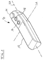
図1は、マシンのための無線遠隔制御システムのハンドヘルドユニット10の簡略化された概略斜視図を示す。マシンとは、それぞれの姿勢を適切な制御によって変えることができる、移動可能な構成要素を有する機器を意味すると理解される。クレーン、コンクリートポンプのアーム、油圧駆動式の商品車両上の装荷昇降台などの遠隔制御が特に考察される。
FIG. 1 shows a simplified schematic perspective view of a
ハンドヘルドユニット10は、そのハウジング12に、あまり詳細には示されないが、少なくとも1つのセンサを含み、それによって、空中におけるハンドヘルドユニット10の動きを検出することができる。動きセンサが回転軸すなわちピッチ軸DAの周りの回転運動、および傾斜軸KAの周りの傾斜運動を検出することができることが特に考察される。ハンドヘルドユニット10の動きは、適切な角度センサおよび姿勢センサによって検出することができる。使用される姿勢および/または動きセンサは、好ましくは、重力または地球の引力に応答し、したがって、ハンドヘルドユニットの回転または傾斜の動きに依存する角度依存的な解像度または最大信号強度を有する。姿勢および/または動きセンサをハンドヘルドユニットのハウジング12に取り付けるために選択される位置に応じて、出力信号は、水平に関する偏向について最大とすることができ、回転する、または垂直に傾くと、ゼロに近づき得る。
The
単に一例として、ここに示すハンドヘルドユニットは、関連するマシン部分を遠隔で制御するために、通常、ユーザの片方の手の親指によって操作することができるジョイスティック14の形態を含むことができる。さらに、さらなる制御オプションを起動させるために作動され得る2つの制御ボタン16、18が示される。これらの制御ボタン16、18のうちの一方は、たとえば、なされた動きに従ってマシンを制御することができるように、動きセンサ(図示せず)によって検出される動きが、制御コマンドに実際に変換される動き制御モードを起動させるために使用することができる。フリップフロップ切替機構の形態では、この制御ボタンが再び作動した場合、この制御ボタンを、その動き制御モードを無効にすることに割り当てることもできる。あるいは、有効または無効にすることを、異なる制御ボタンによって実行することができる。さらに、本例には示されていないが、非常停止スイッチをハンドヘルドユニット10に設けることもできる。示したハンドヘルドユニットは、単に一例にすぎず、その外部の形状に関して、およびさらなるまたは異なる制御に関して異なるように具体化することができる。
By way of example only, the handheld unit shown here may include a form of
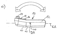
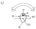
図2に示すように、ハンドヘルドユニット10は、その回転軸DA(ピッチ軸)の周りを回転または枢動することができ、このことが、両方向矢印によって示されている。さらに、ハンドヘルドユニット10(図2b)は、その傾斜軸KAの周りで傾斜し、またはその周りを枢動することもでき、これも同様に両方向矢印によって示されている。動き制御モードがしかるべく有効にされると、回転軸DAまたは傾斜軸KAの周りの動きが動きセンサによって検出され、制御信号に変換され、信号は遠隔で制御されるマシンに送信される。
As shown in FIG. 2, the
本発明の変形形態によれば、回転軸DAの周り、および傾斜軸KAの周りのハンドヘルドユニットの枢動が同時に検出され、制御ユニットによって対応する制御コマンドに変換されることが提供され得る。この場合、この変形形態の開発によれば、オプションで、これらの制御オプションのうちの1つを、ハンドヘルドユニット10で、関連する入力によって一時的に無効にすることができ、その結果、たとえばハンドヘルドユニットを回転軸DAの周りに枢動させる結果として、対応する制御コマンドは全くマシンに通信されず、傾斜軸KAの周りの枢動のみが検出され、制御の目的で変換されることが提供され得る。逆のケースも同様であり、傾斜軸KAの周りの枢動を制御命令として無効になるように切り替えることができ、その結果、回転軸DAの周りの回転のみがマシンのための関連する制御コマンドを生成する。本発明のさらなる変形形態によれば、ハンドヘルドユニット10での能動的な電源投入によって、たとえば押しボタンスイッチを作動させることによっても、これらの制御操作モードを選択することができる。そのような押しボタンスイッチを、たとえば、下部凹型グリップ40、42、44(図2a参照)に設けることができる。関連する制御オプションを選択するために、ロッカスイッチ、サムホイールスイッチなど他の切替要素を設けることもできる。
According to a variant of the invention, it can be provided that the pivoting of the handheld unit around the rotation axis DA and around the tilt axis KA is detected simultaneously and converted into a corresponding control command by the control unit. In this case, according to the development of this variant, optionally one of these control options can be temporarily disabled by the associated input at the
クレーンの場合、たとえば、クレーンフックの上げ下げは、回転軸DAの周りの枢動運動によって制御されることが考察され得る。傾斜軸KAの周りの傾斜運動は、たとえば、ジブに沿ったクレーントロリーの動きの制御のために使用することができる。明らかに、クレーンの設計に応じて、および無線遠隔制御システムの設計、または関連するハンドヘルドユニットの設計に応じて、クレーンのための他の制御オプションも可能である。 In the case of a crane, for example, it can be considered that the raising and lowering of the crane hook is controlled by a pivoting movement about the rotational axis DA. The tilting movement about the tilt axis KA can be used, for example, for controlling the movement of the crane trolley along the jib. Obviously, other control options for the crane are possible, depending on the design of the crane and on the design of the wireless remote control system, or the design of the associated handheld unit.
図1および図2において、2本の相互に直交する軸の周りの回転運動および傾斜運動が検出され得ることが推定される場合であっても、より単純なバージョンで、関連する動きセンサは、軸DAまたは軸KAのうちの一方の周りの動きしか検出できないことが十分考えられる。そのような場合、たとえば、ハンドヘルドユニット10を傾斜軸KAの周りで傾斜させることによって、その回転軸の周りのクレーンの回転がもたらされ、ジョイスティック14を操作することによって、クレーンフックの上げ下げ、およびクレーントロリーの移動が実行されることが可能である。
In FIG. 1 and FIG. 2, even if it is estimated that rotational and tilting motions about two mutually orthogonal axes can be detected, in a simpler version, the associated motion sensor is It is quite conceivable that only movement around one of the axes DA or KA can be detected. In such a case, for example, tilting the
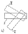
図3は、回転軸DAの周りのハンドヘルドユニット10の様々な移動位置を、模式的な矩形の表現として示す。第1の制御モードでは、空中におけるハンドヘルドユニット10の現在の姿勢Iを基準姿勢として採用することができる。図3に示すように、この基準姿勢Iは、この例では水平に対してわずかに傾いている。そのようなハンドヘルドユニットの快適なポーズは、通常、水平の周りの+/-20°の角度範囲にある。図3の例において、たとえば、制御ボタン16または18(図1)を押すことによって、いわゆる動き制御モードを起動させると、空中におけるハンドヘルドユニット10の現在の姿勢Iが検出され、その後の動き検出のための基準姿勢として採用される。次いで、移動位置IIまたはIIIへの回転軸DAの周りのハンドヘルドユニット10の回転または枢動の動きを、基準姿勢Iに対して評価し、遠隔で制御されるマシンに送信される制御コマンドに変換することができる。移動位置IVは、基準姿勢Iに対する回転の最大角度を超えてしまったハンドヘルドユニット10の姿勢を示す。ハンドヘルドユニット10が基準姿勢または移動位置IIもしくはIIIからそのような移動位置IVになった場合、検出された動きに基づいて、制御コマンドの生成を一時停止することができる(動き制御モードの終了)。たとえば、ユーザが腕が曲がった状態で手にハンドヘルドユニット10を持っており、次いで腕を下に伸ばし、その結果、ハンドヘルドユニットが実質的に垂直に地面の方向を向く場合、移動位置IVに達し得る。
FIG. 3 shows various movement positions of the
図4は、下位図a)およびb)において異なる制御モードを示す。動き制御モードが移動位置IVから始まって起動されると仮定すると、ハンドヘルドユニットは、まず、移動位置IIまたはII'になるはずであり、これは、ハンドヘルドユニット10のあらかじめ設定された基準姿勢Iにほぼ対応する。したがって、たとえば、ハンドヘルドユニット10が移動位置II'に対応する位置に達するとすぐ、次いで検出されるハンドヘルドユニットの動きが、マシンに通信することができる制御コマンドに再度変換される。これは、図2b)において、移動位置IIIおよびVによって示される。動き制御モードは無効にすることができ、その結果、ハンドヘルドユニット10の制御ボタン16、18を作動させることによって、または図3を参照して上述したように、定義された角度範囲を離れ、ハンドヘルドユニットが、たとえば、移動位置IVになることによって、検出された動きは、もはや制御コマンドに変換されない。
FIG. 4 shows the different control modes in the subfigures a) and b). Assuming that the motion control mode is activated starting from the moving position IV, the handheld unit should first be in the moving position II or II ′, which is in the preset reference attitude I of the
図5は、図3による制御モードについての簡略化されたフローチャートを示し、空中における現在の姿勢が基準姿勢として決定される。第1のステップ20では、通常ハンドヘルドユニット10のハウジング12に収容される制御ユニットは、たとえば制御ボタン16、18を押すことによって、動き制御モードが有効にされたかどうかを検出する。検出された動きを制御コマンドに変換し、マシンにこれらの制御コマンドを通信するために使用される動き制御モードを有効にした後、空中におけるハンドヘルドユニットの現在の姿勢(図3のIを参照)が基準姿勢として決定される(ステップ22)。次いで、ステップ24で、現在の姿勢が検出され、基準姿勢Iに関連付けられる。ステップ26は、動き制御モードが無効にされたかどうかについて質問するというものである。そうではない場合(N)、ハンドヘルドユニットがあらかじめ設定された回転/傾斜範囲内で移動しているかどうかについてのチェックがステップ28で行われる。回転/傾斜範囲を離れている場合(N)、ステップ34において、動き制御モードは無効にされ、該当する場合、ユーザが知覚可能な信号がハンドヘルドユニット10で生成される。ステップ28において動きが回転/傾斜範囲内にある場合(Y)、検出された動きに従って計算された制御コマンドがステップ30で生成され、遠隔で制御されるマシン、または駆動されるマシン構成要素に通信される。動き制御モードが有効にされている間、ハンドヘルドユニット10の連続的に変わる移動位置を検出することができるように、さらに対応する制御コマンドを生成することができるように、ステップ24〜30は通常連続的に繰り返される。このループは、矢印31によって示される。
FIG. 5 shows a simplified flowchart for the control mode according to FIG. 3, where the current attitude in the air is determined as the reference attitude. In a
好ましくはハンドヘルドユニットは、検出された動きに応答して、ハンドヘルドユニットで、ユーザが知覚可能な少なくとも1つの出力、具体的には光学および/または音響および/または触覚信号を生成する出力手段(図示せず)も含む。これは、たとえば、ステップ32において行われる。このステップ32は、ステップ24〜32を含む反復ループを拡張し、これは、矢印31を迂回する破線矢印33によって示される。ユーザが知覚可能な信号を生成することによって、ハンドヘルドユニット10の回転または傾斜運動が角偏向を生成する間、およびそれによって制御コマンドが生成される間、聴覚、触覚、または視覚を使用して知覚されるフィードバックをユーザに提供することが可能であり、ユーザは、たとえば、ジョイスティックまたは押しボタンなどを使用した遠隔制御に精通している、またはすでに慣れているので、フィードバックは、ユーザが主観的に経験することができる制御の自信を与える。たとえば、基準姿勢を離れると、およびたとえば、遠隔で制御されるマシン部分の速度に対応する第1のレベルに達すると、ユーザが知覚可能な信号を生成することを明示することができる。この第1のレベルに達し、ハンドヘルドユニットのさらなる傾斜または回転運動がなされると、たとえば、速度コントローラの第2のレベル(高速)に達する可能性があり、このことは、異なる信号、特により強く経験することができる信号によってユーザが知覚可能である。速度が再度速度レベルIIを離れ、レベルIに戻った場合、これは、同様に適切な信号によってユーザが知覚可能になり得る。ユーザが知覚可能な信号が触覚および/または音響信号の形態である場合、ユーザは、マシンを遠隔制御しながら、遠隔で制御されるマシンの構成要素に視覚的に集中することができ、ハンドヘルドユニット10を見ることを強いられる必要がない。ユーザがハンドヘルドユニット10で実行する動きは、フィードバックの形態で音響および/または触覚信号によってユーザが知覚可能となり、その結果、マシンの所望の遠隔操作を実行することが可能であるように、ユーザは、知覚された信号に従ってハンドヘルドユニット10でさらなる動きまたは反対の動きを実行することができる。
Preferably, the handheld unit is responsive to the detected movement to generate at least one output perceivable by the user, specifically optical and / or acoustic and / or tactile signals, in the handheld unit (see FIG. (Not shown). This is done, for example, in
一例として上述した方法による、いくつかのレベルに達すると、ユーザが知覚可能な信号を出力することに加えて、そのような信号を、検出された動きに比例して出力することもできる。それによって、たとえば、検出された回転または傾斜の角度の増加または減少を音響的/触覚的に経験することが可能となることが考えられ、角度の増加の場合、角度の減少の場合とは異なる信号が出力されることが十分可能である。ハンドヘルドユニットが何らかの角度位置で依然として保持されている場合、関連する信号は出力されず、ハンドヘルドユニットが動くまで、再度出力されない。あるいは、全動き制御モードの間、音響および/または触覚信号が常に出力され、好ましくは検出された回転または傾斜角度に比例するように設計されることも可能である。たとえば、したがって、ハンドヘルドユニットを基準姿勢に、またはそれに近い姿勢に保つとき、ユーザがごく弱い振動を感知することが可能である。ハンドヘルドユニットの回転または傾斜運動の間、ハンドヘルドユニットの枢動の増加とともに振動が増加し、その結果、ユーザは基準姿勢から離れる動きを触覚的に検出することができる。明らかに、この信号伝達は、音響的に行うこともできる。 In addition to outputting a signal that can be perceived by the user upon reaching some levels, according to the method described above as an example, such a signal can also be output in proportion to the detected motion. It is possible, for example, to be able to experience an increase / decrease in the detected rotation or tilt angle acoustically / tactilely, where the angle increase is different from the angle decrease It is fully possible that a signal is output. If the handheld unit is still held in any angular position, the associated signal will not be output and will not be output again until the handheld unit moves. Alternatively, acoustic and / or haptic signals can always be output during the full motion control mode, preferably designed to be proportional to the detected rotation or tilt angle. For example, therefore, it is possible for the user to sense very weak vibrations when keeping the handheld unit at or near the reference posture. During the rotation or tilting movement of the handheld unit, the vibration increases as the handheld unit pivots, so that the user can tactilely detect movement away from the reference posture. Obviously, this signaling can also be done acoustically.
ここでは、ユーザが知覚可能な信号の比例した出力は、検出された動きと信号強度との間の正比例の依存関係に限定されない。代わりに、人間の感覚によりよく適した対数信号分配も考察される。音響および触覚すなわち振動のフィードバック信号(ユーザが知覚可能な信号)は両方とも、たとえば、振動パルスまたは振動パルスの短いバーストの連鎖から構成することができ、振動パルス間の間隔は、回転または傾斜の角度が増加するにつれて減少し、したがって、感知される信号の強度が増加することになる。 Here, the proportional output of the signal that can be perceived by the user is not limited to the direct proportional dependency between the detected motion and the signal strength. Instead, logarithmic signal distribution better suited to the human sense is also considered. Both acoustic and tactile or vibration feedback signals (user perceptible signals) can consist of, for example, vibration pulses or a chain of short bursts of vibration pulses, and the spacing between vibration pulses can be rotational or tilting. As the angle increases, it decreases and therefore the intensity of the sensed signal will increase.
基準姿勢に達したとき、または電源切断状況に達したとき、たとえば基準姿勢に対して約+/-45°の角度に達すると、ハンドヘルドユニットでの音響および/または触覚および/または光学出力を出力することもできる。 Outputs acoustic and / or tactile and / or optical output from the handheld unit when the reference posture is reached, or when the power-off condition is reached, for example when an angle of about +/- 45 ° is reached with respect to the reference posture You can also
本発明の拡張された変形形態(図示せず)によれば、ハンドヘルドユニット10は、制御されるマシンからのフィードバック情報を受信するように構成されたフィードバック受信機を含み、この場合、そのようなフィードバック情報を送信するフィードバック送信機がマシンに設けられると仮定される。最も単純なケースでは、マシン上の受信機は、制御コマンドを受け取ったことを通知するフィードバック送信機を含むことができ、したがって、フィードバック情報は、制御コマンドの受信の確認を含んでいる。これらの予想される無線受信確認がハンドヘルドユニット10によって登録されていない場合、ハンドヘルドユニット10の関連の出力手段は、障害の可能性をユーザに通知することができる。
According to an extended variant of the invention (not shown), the
本発明による無線遠隔制御システムのさらなる開発レベルにおいて、前記システムは、その瞬間の移動可能なマシン部分の実際の位置についての、および/または前記部分の動きの状態についてのデータを取得するセンサデバイス、およびフィードバック情報としてこのセンサデバイスからデータを送信するマシン上のフィードバック送信機を含み、ハンドヘルドユニットのフィードバック受信機は、このフィードバック情報を受信し、制御ユニットにそれを渡すことができる。本発明の変形形態によれば、制御ユニットは、次いで、受信されたフィードバック情報に従ってマシンのための制御コマンドを修正することができる。表示デバイスの形態の出力手段は、その瞬間の実際の位置、および/またはハンドヘルドユニットの瞬間的な姿勢によって定義される設定点位置からの実際の位置の現在の偏差、および/または移動可能なマシン部分の動きの速度を表すように設計することもできる。この文脈において、光学および/または音響および/または触覚表示または出力も可能である。 In a further development level of the wireless remote control system according to the invention, the system obtains data about the actual position of the movable machine part at the moment and / or about the state of movement of the part, And a feedback transmitter on the machine that transmits data from the sensor device as feedback information, the feedback receiver of the handheld unit can receive this feedback information and pass it to the control unit. According to a variant of the invention, the control unit can then modify the control command for the machine according to the received feedback information. The output means in the form of a display device is the actual position of the moment and / or the current deviation of the actual position from the set point position defined by the momentary attitude of the handheld unit and / or a movable machine It can also be designed to represent the speed of movement of the part. In this context, optical and / or acoustic and / or tactile displays or outputs are also possible.
10 ハンドヘルドユニット
12 ハウジング
14 ジョイスティック
16 制御ボタン
18 制御ボタン
40 下部凹型グリップ
42 下部凹型グリップ
44 下部凹型グリップ
10 Handheld unit
12 Housing
14 Joystick
16 Control button
18 Control buttons
40 Lower concave grip
42 Lower concave grip
44 Lower concave grip
Claims (17)
前記マシンに割り当てられた無線受信機と、
制御ユニット、送信機、および少なくとも1つの動きセンサを含むハンドヘルドユニット(10)とを含み、
前記制御ユニットが、ユーザによって発行された制御コマンドを前記送信機に通信し、前記送信機に、前記制御コマンドを前記受信機に送信させるように構成され、
動き制御モードにおいて、前記検出された動きを、前記制御ユニットによって、送信機と受信機との間の無線送信によって前記マシンに通信することができる制御コマンドに変換することができるよう、少なくとも1つの傾斜軸またはピッチ軸(KA、DA)の周りの空中における前記ハンドヘルドユニット(10)の動きを前記動きセンサによって検出することができ、
前記動き制御モードを、前記ハンドヘルドユニット(10)でユーザ入力によって起動することができる、無線遠隔制御システムにおいて、
前記制御ユニットが、前記動き制御モードを起動させると、空中における前記ハンドヘルドユニット(10)の現在の姿勢(I)が現在の基準姿勢(I)として検出され、その結果、この現在の基準姿勢(I)に対する動きを前記動きセンサによって検出することができ、制御コマンドとして前記制御ユニットによって前記マシンに通信することができるようにも構成されることを特徴とする無線遠隔制御システム。 A wireless remote control system of a machine comprising at least one machine drive for a movable machine part, the machine drive being controlled by said wireless remote control system;
A radio receiver assigned to the machine;
A control unit, a transmitter, and a handheld unit (10) including at least one motion sensor,
The control unit is configured to communicate a control command issued by a user to the transmitter, causing the transmitter to transmit the control command to the receiver;
In motion control mode, the detected motion can be converted by the control unit into a control command that can be communicated to the machine by wireless transmission between a transmitter and a receiver. The movement of the handheld unit (10) in the air around the tilt axis or pitch axis (KA, DA) can be detected by the motion sensor;
In a wireless remote control system, wherein the motion control mode can be activated by user input on the handheld unit (10),
When the control unit activates the motion control mode, the current attitude (I) of the handheld unit (10) in the air is detected as the current reference attitude (I), and as a result, the current reference attitude (I A wireless remote control system configured to be able to detect movement with respect to I) by the movement sensor and to communicate to the machine by the control unit as a control command.
前記無線遠隔制御システムのハンドヘルドユニット(10)においてユーザによって発行された制御コマンドを、前記ハンドヘルドユニットの送信機から前記マシンに、特に関連する受信機に送信するステップと、
少なくとも1つの傾斜軸またはピッチ軸(KA、DA)の周りの空中における前記ハンドヘルドユニット(10)の動きを検出するステップであり、前記検出された動きが動き制御モードにおいて前記マシンに通信される制御コマンドに変換されるステップとを含み、
前記ハンドヘルドユニット(10)でのユーザ入力によって前記動き制御モードが起動される(20)、操作方法において、
前記動き制御モードを起動させる(20)と、空中における前記ハンドヘルドユニットの現在の姿勢が現在の基準姿勢として検出され(22)、その結果、この現在の基準姿勢に対する動きを検出する(24)ことができ、制御コマンドとして前記マシンに通信することができる(30)ことを特徴とする操作方法。 An operating method for a wireless remote control system of a machine having at least one machine drive for a movable machine part, the machine drive being controlled by said wireless remote control system,
Sending a control command issued by a user in the handheld unit (10) of the wireless remote control system from the transmitter of the handheld unit to the machine, in particular to an associated receiver;
Detecting movement of the handheld unit (10) in the air around at least one tilt axis or pitch axis (KA, DA), the detected movement being communicated to the machine in a motion control mode A step converted into a command,
The motion control mode is activated by a user input at the handheld unit (10) (20).
When the motion control mode is activated (20), the current posture of the handheld unit in the air is detected as the current reference posture (22), and as a result, the motion with respect to the current reference posture is detected (24). An operation method characterized by being capable of communicating with the machine as a control command (30).
Applications Claiming Priority (1)
| Application Number | Priority Date | Filing Date | Title |
|---|---|---|---|
| PCT/EP2010/062706 WO2012028175A1 (en) | 2010-08-31 | 2010-08-31 | Radio remote control with position sensor system |
Publications (2)
| Publication Number | Publication Date |
|---|---|
| JP2013536660A true JP2013536660A (en) | 2013-09-19 |
| JP2013536660A5 JP2013536660A5 (en) | 2014-02-27 |
Family
ID=44166489
Family Applications (1)
| Application Number | Title | Priority Date | Filing Date |
|---|---|---|---|
| JP2013526321A Pending JP2013536660A (en) | 2010-08-31 | 2010-08-31 | Wireless remote control by position sensor system |
Country Status (9)
| Country | Link |
|---|---|
| US (1) | US8866597B2 (en) |
| EP (1) | EP2612308B1 (en) |
| JP (1) | JP2013536660A (en) |
| CN (1) | CN103069463A (en) |
| DK (1) | DK2612308T3 (en) |
| ES (1) | ES2624862T3 (en) |
| PL (1) | PL2612308T3 (en) |
| RU (1) | RU2534934C2 (en) |
| WO (1) | WO2012028175A1 (en) |
Cited By (1)
| Publication number | Priority date | Publication date | Assignee | Title |
|---|---|---|---|---|
| WO2018037699A1 (en) * | 2016-08-23 | 2018-03-01 | ソニー株式会社 | Control system, control apparatus, and control method |
Families Citing this family (25)
| Publication number | Priority date | Publication date | Assignee | Title |
|---|---|---|---|---|
| US20130293362A1 (en) * | 2012-05-03 | 2013-11-07 | The Methodist Hospital Research Institute | Multi-degrees-of-freedom hand controller |
| EP2813910A1 (en) * | 2013-06-10 | 2014-12-17 | Siemens Aktiengesellschaft | Handheld control unit with combined signal evaluation |
| CN104639966A (en) * | 2015-01-29 | 2015-05-20 | 小米科技有限责任公司 | Method and device for remote control |
| CN105678990A (en) * | 2015-12-31 | 2016-06-15 | 赵旭 | Remote controller, and detection and control method thereof |
| JP1584385S (en) * | 2016-05-10 | 2017-08-21 | ||
| EP3279881A1 (en) * | 2016-08-05 | 2018-02-07 | Alexander Hakenjos | Remote control and method for controlling the same |
| US10198086B2 (en) | 2016-10-27 | 2019-02-05 | Fluidity Technologies, Inc. | Dynamically balanced, multi-degrees-of-freedom hand controller |
| US10331233B2 (en) | 2016-10-27 | 2019-06-25 | Fluidity Technologies, Inc. | Camera and sensor controls for remotely operated vehicles and virtual environments |
| US10331232B2 (en) | 2016-10-27 | 2019-06-25 | Fluidity Technologies, Inc. | Controller with situational awareness display |
| US10324487B2 (en) | 2016-10-27 | 2019-06-18 | Fluidity Technologies, Inc. | Multi-axis gimbal mounting for controller providing tactile feedback for the null command |
| US10520973B2 (en) | 2016-10-27 | 2019-12-31 | Fluidity Technologies, Inc. | Dynamically balanced multi-degrees-of-freedom hand controller |
| US10664002B2 (en) | 2016-10-27 | 2020-05-26 | Fluidity Technologies Inc. | Multi-degrees-of-freedom hand held controller |
| CN106683384B (en) * | 2017-02-28 | 2023-11-24 | 国网山东省电力公司烟台供电公司 | Intelligent remote controller, household appliance and method |
| EP3396478B1 (en) | 2017-04-28 | 2023-06-14 | Deere & Company | Apparatus, method and computer programme for controlling a machine |
| EP3701349A4 (en) | 2017-10-27 | 2021-07-28 | Fluidity Technologies, Inc. | Camera and sensor controls for remotely operated vehicles and virtual environments |
| EP3701216A4 (en) | 2017-10-27 | 2021-09-22 | Fluidity Technologies, Inc. | Multi-axis gimbal mounting for controller providing tactile feedback for the null command |
| CN111511449A (en) | 2017-10-27 | 2020-08-07 | 流体技术股份有限公司 | Controller with context aware display |
| EP3771458A1 (en) * | 2019-07-29 | 2021-02-03 | TRUMPF Medizin Systeme GmbH + Co. KG | Remote control for a medical apparatus, system of the remote control and the medical apparatus, and method for operating the medical apparatus |
| US11908574B2 (en) * | 2019-07-29 | 2024-02-20 | Trumpf Medizin Systeme Gmbh + Co. Kg | Remote control for a medical apparatus, system of the remote control and the medical apparatus and method for operating the medical apparatus |
| US11599107B2 (en) | 2019-12-09 | 2023-03-07 | Fluidity Technologies Inc. | Apparatus, methods and systems for remote or onboard control of flights |
| WO2021115505A1 (en) * | 2019-12-11 | 2021-06-17 | Ged Gesellschaft Für Elektronik Und Design Mbh | Device for training the sense of equilibrium |
| US11614766B2 (en) * | 2020-04-09 | 2023-03-28 | Caterpillar Inc. | Machine joystick with comfort and accessibility features |
| IT202000028481A1 (en) * | 2020-11-26 | 2022-05-26 | Aisa Di Zanette Dino | PORTABLE REMOTE CONTROL DEVICE PREFERABLE FOR HOUSEHOLD USE |
| US11662835B1 (en) | 2022-04-26 | 2023-05-30 | Fluidity Technologies Inc. | System and methods for controlling motion of a target object and providing discrete, directional tactile feedback |
| US11696633B1 (en) | 2022-04-26 | 2023-07-11 | Fluidity Technologies Inc. | System and methods for controlling motion of a target object and providing discrete, directional tactile feedback |
Citations (7)
| Publication number | Priority date | Publication date | Assignee | Title |
|---|---|---|---|---|
| JPH11262073A (en) * | 1998-03-13 | 1999-09-24 | Mitsubishi Electric Corp | Remote control system |
| JP2003111171A (en) * | 2001-09-26 | 2003-04-11 | Yamaha Corp | Remote controller |
| JP2004173003A (en) * | 2002-11-20 | 2004-06-17 | Toshiba Corp | Broadcast receiver, code signal output device and its control method |
| JP2004236034A (en) * | 2003-01-30 | 2004-08-19 | Nippon Hoso Kyokai <Nhk> | Remote control signal transmitter |
| JP2006072992A (en) * | 2004-08-16 | 2006-03-16 | Mitsubishi Electric Research Laboratories Inc | Single common graphical user interface for network of home appliance, and home appliance network |
| JP2007531113A (en) * | 2004-03-23 | 2007-11-01 | 富士通株式会社 | Identification of mobile device tilt and translational components |
| JP2009189727A (en) * | 2008-02-18 | 2009-08-27 | Kyushu Hitachi Maxell Ltd | Massager |
Family Cites Families (14)
| Publication number | Priority date | Publication date | Assignee | Title |
|---|---|---|---|---|
| US5444462A (en) * | 1991-12-16 | 1995-08-22 | Wambach; Mark L. | Computer mouse glove with remote communication |
| US5598187A (en) * | 1993-05-13 | 1997-01-28 | Kabushiki Kaisha Toshiba | Spatial motion pattern input system and input method |
| US6346891B1 (en) * | 1998-08-31 | 2002-02-12 | Microsoft Corporation | Remote control system with handling sensor in remote control device |
| SE521051C2 (en) * | 2001-11-16 | 2003-09-23 | Volvo Penta Ab | Remote control system for a vehicle. |
| JP2004120577A (en) * | 2002-09-27 | 2004-04-15 | Alps Electric Co Ltd | Equipment controller |
| DE102004009561A1 (en) * | 2003-02-27 | 2004-11-11 | Karlheinz Lederer | Remote control system using image pickup to set reference point for remote control by mobile phone |
| US7173604B2 (en) * | 2004-03-23 | 2007-02-06 | Fujitsu Limited | Gesture identification of controlled devices |
| RU55760U1 (en) * | 2006-03-22 | 2006-08-27 | Общество с ограниченной ответственностью "Научно-производственное предприятие "КОМПЛЕКСЫ и СИСТЕМЫ" (ООО НПП "КОМПЛЕКСЫ и СИСТЕМЫ") | CRANE REMOTE CONTROL SYSTEM (CDS) |
| US20080150749A1 (en) * | 2006-12-21 | 2008-06-26 | Tai-Hung Lin | Wireless control system for controlling linear actuators |
| JP4940118B2 (en) | 2007-12-10 | 2012-05-30 | 株式会社キトー | Operation control device for traveling crane |
| JP5011170B2 (en) | 2008-03-05 | 2012-08-29 | 株式会社キトー | Operation control device and operation control method for traveling crane |
| JP5011169B2 (en) | 2008-03-05 | 2012-08-29 | 株式会社キトー | Operation control device for traveling crane |
| US8503932B2 (en) * | 2008-11-14 | 2013-08-06 | Sony Mobile Comminications AB | Portable communication device and remote motion input device |
| JP5348760B2 (en) * | 2009-05-08 | 2013-11-20 | 本田技研工業株式会社 | Remote control device for work equipment |
-
2010
- 2010-08-31 PL PL10757578T patent/PL2612308T3/en unknown
- 2010-08-31 RU RU2013114302/08A patent/RU2534934C2/en active
- 2010-08-31 EP EP10757578.9A patent/EP2612308B1/en active Active
- 2010-08-31 ES ES10757578.9T patent/ES2624862T3/en active Active
- 2010-08-31 JP JP2013526321A patent/JP2013536660A/en active Pending
- 2010-08-31 US US13/818,148 patent/US8866597B2/en active Active
- 2010-08-31 WO PCT/EP2010/062706 patent/WO2012028175A1/en active Application Filing
- 2010-08-31 DK DK10757578.9T patent/DK2612308T3/en active
- 2010-08-31 CN CN2010800688473A patent/CN103069463A/en active Pending
Patent Citations (7)
| Publication number | Priority date | Publication date | Assignee | Title |
|---|---|---|---|---|
| JPH11262073A (en) * | 1998-03-13 | 1999-09-24 | Mitsubishi Electric Corp | Remote control system |
| JP2003111171A (en) * | 2001-09-26 | 2003-04-11 | Yamaha Corp | Remote controller |
| JP2004173003A (en) * | 2002-11-20 | 2004-06-17 | Toshiba Corp | Broadcast receiver, code signal output device and its control method |
| JP2004236034A (en) * | 2003-01-30 | 2004-08-19 | Nippon Hoso Kyokai <Nhk> | Remote control signal transmitter |
| JP2007531113A (en) * | 2004-03-23 | 2007-11-01 | 富士通株式会社 | Identification of mobile device tilt and translational components |
| JP2006072992A (en) * | 2004-08-16 | 2006-03-16 | Mitsubishi Electric Research Laboratories Inc | Single common graphical user interface for network of home appliance, and home appliance network |
| JP2009189727A (en) * | 2008-02-18 | 2009-08-27 | Kyushu Hitachi Maxell Ltd | Massager |
Cited By (4)
| Publication number | Priority date | Publication date | Assignee | Title |
|---|---|---|---|---|
| WO2018037699A1 (en) * | 2016-08-23 | 2018-03-01 | ソニー株式会社 | Control system, control apparatus, and control method |
| JPWO2018037699A1 (en) * | 2016-08-23 | 2019-06-20 | ソニー株式会社 | Control system, control device, and control method |
| US10916123B2 (en) | 2016-08-23 | 2021-02-09 | Sony Corporation | Control system, control apparatus, and control method |
| JP7002453B2 (en) | 2016-08-23 | 2022-01-20 | ソニーグループ株式会社 | Control system, control device, and control method |
Also Published As
| Publication number | Publication date |
|---|---|
| US8866597B2 (en) | 2014-10-21 |
| EP2612308B1 (en) | 2017-04-05 |
| PL2612308T3 (en) | 2017-09-29 |
| WO2012028175A1 (en) | 2012-03-08 |
| RU2013114302A (en) | 2014-10-10 |
| DK2612308T3 (en) | 2017-07-31 |
| RU2534934C2 (en) | 2014-12-10 |
| ES2624862T3 (en) | 2017-07-17 |
| EP2612308A1 (en) | 2013-07-10 |
| US20130147611A1 (en) | 2013-06-13 |
| CN103069463A (en) | 2013-04-24 |
Similar Documents
| Publication | Publication Date | Title |
|---|---|---|
| JP2013536660A (en) | Wireless remote control by position sensor system | |
| JP2013536660A5 (en) | ||
| EP2386387B1 (en) | Engineering vehicle arm support controller control system engineering vehicle and control method | |
| US11760444B2 (en) | Method and system for operating a hydrofoil board | |
| US10961086B2 (en) | Assembly of a controller and of a mobile control module | |
| JP2013025664A (en) | Input device, input method and control system | |
| CN108290722B (en) | Assembly comprising a control device and a mobile control module, and hydraulic lifting device | |
| CN103359642B (en) | Tower crane work monitoring system, method thereof and tower crane | |
| KR20150068598A (en) | Electromotive apparatus for assisting user in walking | |
| US20210223781A1 (en) | Systems and Methods for Controlling Mobility Devices | |
| WO2007080438A1 (en) | Charging stand | |
| KR101888050B1 (en) | Custom aided walking system for elderly and operation method thereof | |
| US20220297984A1 (en) | Construction and/or material-handling machine | |
| KR101602930B1 (en) | A controll apparatus for hoist | |
| KR101459322B1 (en) | Device limiting a joystick | |
| JP7364999B2 (en) | Boom operating system | |
| KR102025627B1 (en) | Electronic handcuff device and electronic handcuff system including the same | |
| KR102020374B1 (en) | Smart cane | |
| CN114495469A (en) | Vehicle control method and device, electronic equipment and storage medium | |
| JP2022080648A (en) | Industrial remote controller | |
| GB2602635A (en) | Input device | |
| KR20130008310A (en) | Remote controller capable of controlling diplay unit or content displayed in display unit by sensing grasping power and user's motion | |
| KR20170108417A (en) | Position control system for flight using by smart phone | |
| EP2035256A2 (en) | Control device of a demountable of a vehicle and its use, arrangement and method for controlling a demountable of a vehicle |
Legal Events
| Date | Code | Title | Description |
|---|---|---|---|
| A621 | Written request for application examination |
Free format text: JAPANESE INTERMEDIATE CODE: A621 Effective date: 20130617 |
|
| A521 | Written amendment |
Free format text: JAPANESE INTERMEDIATE CODE: A523 Effective date: 20140110 |
|
| A977 | Report on retrieval |
Free format text: JAPANESE INTERMEDIATE CODE: A971007 Effective date: 20140226 |
|
| A131 | Notification of reasons for refusal |
Free format text: JAPANESE INTERMEDIATE CODE: A131 Effective date: 20140331 |
|
| A521 | Written amendment |
Free format text: JAPANESE INTERMEDIATE CODE: A523 Effective date: 20140627 |
|
| A02 | Decision of refusal |
Free format text: JAPANESE INTERMEDIATE CODE: A02 Effective date: 20141201 |