EP2612308B1 - Radio remote control with position sensor system - Google Patents
Radio remote control with position sensor system Download PDFInfo
- Publication number
- EP2612308B1 EP2612308B1 EP10757578.9A EP10757578A EP2612308B1 EP 2612308 B1 EP2612308 B1 EP 2612308B1 EP 10757578 A EP10757578 A EP 10757578A EP 2612308 B1 EP2612308 B1 EP 2612308B1
- Authority
- EP
- European Patent Office
- Prior art keywords
- machine
- remote control
- radio remote
- control system
- designed
- Prior art date
- Legal status (The legal status is an assumption and is not a legal conclusion. Google has not performed a legal analysis and makes no representation as to the accuracy of the status listed.)
- Active
Links
- 230000033001 locomotion Effects 0.000 claims description 155
- 230000003287 optical effect Effects 0.000 claims description 9
- 230000003213 activating effect Effects 0.000 claims description 4
- 230000005540 biological transmission Effects 0.000 claims description 4
- 230000004044 response Effects 0.000 claims description 3
- 230000006870 function Effects 0.000 description 7
- 238000011161 development Methods 0.000 description 4
- 230000004913 activation Effects 0.000 description 3
- 230000009467 reduction Effects 0.000 description 3
- 230000001447 compensatory effect Effects 0.000 description 2
- 230000007423 decrease Effects 0.000 description 2
- 238000001514 detection method Methods 0.000 description 2
- 230000007935 neutral effect Effects 0.000 description 2
- 230000010355 oscillation Effects 0.000 description 2
- 230000008447 perception Effects 0.000 description 2
- 241000282326 Felis catus Species 0.000 description 1
- 230000001133 acceleration Effects 0.000 description 1
- 230000009471 action Effects 0.000 description 1
- 238000013459 approach Methods 0.000 description 1
- 230000002457 bidirectional effect Effects 0.000 description 1
- 238000006243 chemical reaction Methods 0.000 description 1
- 238000012790 confirmation Methods 0.000 description 1
- 238000010276 construction Methods 0.000 description 1
- 238000013016 damping Methods 0.000 description 1
- 230000001419 dependent effect Effects 0.000 description 1
- 238000013461 design Methods 0.000 description 1
- 238000006073 displacement reaction Methods 0.000 description 1
- 230000005484 gravity Effects 0.000 description 1
- 238000000034 method Methods 0.000 description 1
- 230000000750 progressive effect Effects 0.000 description 1
- 230000011664 signaling Effects 0.000 description 1
- 210000003813 thumb Anatomy 0.000 description 1
- 230000001960 triggered effect Effects 0.000 description 1
Images


Classifications
-
- G—PHYSICS
- G08—SIGNALLING
- G08C—TRANSMISSION SYSTEMS FOR MEASURED VALUES, CONTROL OR SIMILAR SIGNALS
- G08C17/00—Arrangements for transmitting signals characterised by the use of a wireless electrical link
- G08C17/02—Arrangements for transmitting signals characterised by the use of a wireless electrical link using a radio link
-
- G—PHYSICS
- G08—SIGNALLING
- G08C—TRANSMISSION SYSTEMS FOR MEASURED VALUES, CONTROL OR SIMILAR SIGNALS
- G08C2201/00—Transmission systems of control signals via wireless link
- G08C2201/30—User interface
- G08C2201/32—Remote control based on movements, attitude of remote control device
-
- G—PHYSICS
- G08—SIGNALLING
- G08C—TRANSMISSION SYSTEMS FOR MEASURED VALUES, CONTROL OR SIMILAR SIGNALS
- G08C2201/00—Transmission systems of control signals via wireless link
- G08C2201/50—Receiving or transmitting feedback, e.g. replies, status updates, acknowledgements, from the controlled devices
Definitions
- the present invention relates to a radio remote control of a crane, a boom, a loading bridge and / or a hoist with various moving components (machine) with at least one controllable by the radio remote machine drive a movable machine part, comprising a machine associated with the radio receiving device, a handset with a control unit , a transmitting device and at least one motion sensor, wherein the control unit is adapted to transmit control commands caused by a user to the transmitting device and to cause the transmitting device for transmitting the control commands to the receiving device, and wherein by means of the motion sensor movements of the handset in the room by at least a tilting or tilting axis (KA, DA) can be detected, such that in a movement operating mode the detected movements can be converted by the control unit into control commands which are sent to the machine by F unkübertragung between transmitting device and receiving device can be transmitted, wherein the movement mode of operation can be activated by a user input on the handset.
- KA, DA tilting or tilting axis
- a particularly preferred although not exclusive field of application of the present invention is the control of cranes and hoists.
- a jib crane such as a construction crane, e.g. the orientation of the boom (rotation angle), the movement of the cat and the movement of the hook are controlled with a suitably designed radio remote control according to the invention.
- Position sensors are also installed today, for example, in mobile phones, so that the orientation of such a device, in particular its display can be determined to adjust the display in the display according to the orientation of the device.
- radio remote controls are from the US 2005/0212911 A1 , of the DE 10 2004 009 561 A1 and the US 2008/0150749 A1 known.
- the US 2005/0212911 A1 discloses in general the configuration or use of a handheld device, for example a mobile telephone, as a radio remote control for all possible devices, partly with movable divider and the radio remote control corresponds in its functionality to the other features of the preamble of claim 1.
- the DE 10 2004 009 561 A1 discloses the use of a smartphone as a remote control for controlling a device detected by the camera by means of movements of the smartphone.
- the US 2008/0150749 A1 discloses a remote control for a reclining or seating device, for example a hospital bed, the lying or Sirzflä- has several elements, each of which is separately adjustable by a liner motor. The operating state of the respective linear motors is sent back to the remote control.
- the object of the invention is to improve a generic radio remote control in terms of intuitive operation by a user.
- the receiving device has a feedback transmitter and is adapted to activate the feedback transmitter for the transmission of feedback information upon receipt of control commands, and wherein the handset set up for receiving the return information and connected to the control unit feedback receiver and controlled by the control unit having acoustic and / or haptic display device by means of which operating function information of the radio remote control in accordance with the reception of feedback signals from the feedback transmitter can be displayed.
- control unit it is possible to determine the current reference position in a comfortable hand position for a user.
- a handset of a radio remote control is often not kept exactly horizontal, but a natural attitude of the human hand causes the handset is held with a slight inclination in the upward direction.
- This natural posture can then be defined as the current reference position or as a kind of neutral position, so that movements detected by the motion sensor, such as turning, tilting or tilting of the handset, can be detected and converted into control commands.
- Based on such a natural position of the human hand also results in an optimal utilization of the possible movements by the user for the purpose of controlling a corresponding machine drive.
- the radio remote control is set up such that upon activation of the motion mode, the current position of the handset is detected in space and compared with a predetermined reference position, and that detected movements are only as control commands to the machine can be transmitted, if the radio remote control has been brought at least approximately in the predetermined reference position, wherein for the generation of control commands movements are detected relative to the predetermined reference position.
- the predetermined reference position may be, for example, a substantially horizontal orientation of the handset in space. This predetermined reference position must be reached or adjusted starting from a position of the handset in the room in which the motion control is activated. Once the handset has been brought into a current position or is already in activating the motion control, which corresponds approximately to the predetermined reference position, d. H. meets this predetermined reference position within a tolerance range, then further movements of the handset are detected based on the predetermined reference position and converted into control commands that can be transmitted to the machine.
- the invention allows intuitive operation and control of a machine by means of a hand-held device that contains motion sensors and whose control unit allows transmission of detected movements as a control command to the machine.
- a radio remote control In this regard, reference should be made to two different control operation possibilities that may be implemented in respective embodiments of a radio remote control according to the present invention.
- a first control mode the activation of the motion mode is performed by operating a switch.
- a switch preferably any existing safety relay or the like.
- the machine is unlocked and it follows the referencing of the handset according to one of the aforementioned referencing options.
- By moving the handset relative to the detected reference position is then the specification of the controlled movement of the machine part, whereby by opposite directions of movement of the handset relative to the reference position control commands can be generated, which also cause the machine part to move in corresponding opposite directions.
- the amount of the movement to be controlled for example the speed amount or the acceleration amount, can then also be specified.
- An example of this is provided, for example, by specifying both the direction and the amount of the movement of the machine part to be controlled by rotating the handset relative to a reference position detected when the motion mode is activated by +/- 30 °, for example Plus area represents a direction of movement and the minus area represents the opposite direction of movement of the machine part.
- a second control mode provides that e.g. two contacts or push buttons are provided, which are to be actuated to activate the movement mode of operation, wherein one of the keys associated with a direction of movement of the machine part, whereas the other button is associated with the opposite direction of movement of the machine part.
- the movement of the handset relative to the respective reference position would then be e.g. specify only the amount of the controlled speed of the machine part.
- the motion mode of operation is triggered by actuation of a switch on the handset and maintained by continued contact of that switch to control the movement of the machine part. Releasing this switch will then result in no further control commands being transmitted to control the movement of the machine part. It is therefore a kind of deadman circuit.
- latching switches are provided for user input on the handset, by means of which the user can activate the movement mode of operation by an active switching operation on such a latching switch.
- the output perceivable to the user of the handset improves the intuitive remote control of a machine.
- the user will be supported in an intuitive way in the machine operation by means of movements of the handset.
- the output is a kind of feedback to the user, so that the human-machine interface can be optimized.
- the output means are set up such that the output perceptible to the user is generated as a function of signals output by the motion sensor.
- the output means may be arranged to generate the output perceptible to the user in a stepwise manner in response to the achievement of certain signal strengths output by the motion sensor.
- another signal could be output when an extreme value of the possible motion is reached.
- the output means may be arranged to generate the output perceptible to the user in proportion to the signal strength output by the motion sensor.
- the output means may be arranged to generate the output perceptible to the user in proportion to the signal strength output by the motion sensor.
- the output perceptible to the user may be a predetermined one Characteristic are generated in accordance with the signal strength output by the motion sensor.
- the characteristic curve can be optimized depending on the type of control, so that the dependence of the output perceptible on the user of the signal strength output by the motion sensor is directly proportional, ie linear, or degressive or progressive. In particular, a logarithmic characteristic also comes into question.
- the perceptible for the user output of at least one output means is differentially, so only when the signal strength output by the motion sensor changes.
- a differential or dynamic output normally provides the user with a sufficient subjective feedback feeling of the radio remote control and, on average, places a relatively small burden on the power supply of the handset since during the phases of constant signal output of the motion sensor the output means need not be activated.
- the control unit is preferably set up in such a way that movements detected by the movement sensor or a movement sensor in a working rotation or tilting range of a maximum of about -45 ° to + 45 °, in particular -30 ° to + 30 °, cause an associated horizontal rotation or tilting movement .
- Tilting axis are converted into control commands for the machine.
- Such a limitation of the range of motion convertible into control commands for the machine serves, on the one hand, for ergonomic handling of the handheld device since movements in a larger angular range are inconvenient by means of the human hand.
- an angular range defined in this way can also be used to define positions of the handheld device in which the motion control is switched off by means of the handheld device and no further ones Control commands are sent to the machine more due to detected movements.
- the output means is set up in such a way that it indicates an approximation to the maximum rotational or tilting movement and / or leaving the working rotary or tilting range by a corresponding output perceptible to the user.
- control unit can be set up in such a way that no further control commands due to detected movements are generated when leaving the work turning or tilting area until further notice.
- safety-related control commands e.g. Stop commands are sent from the handset to the machine when the working turn or tilt range is exited.
- leaving a preferred angular range or movement range preferably affects only the machine control by means of movement of the handset, but not the activation of the machine by means of any other controls on the handset, such as push buttons, joystick or the like
- leaving the working rotation or tilting range in the machine control it is determined whether the machine will then remain in its current state or be brought into a neutral position. It is also to be determined whether the movements of all controllable by the radio remote machine parts in the case of leaving the Häitch- or tilting should be stopped or whether only those drives which are controlled by the motion control, stopped.
- Such operating concepts can be determined taking into account corresponding security concepts and standards.
- the receiving device has a feedback transmitter and is configured to activate the feedback transmitter for the transmission of feedback information upon receipt of control commands, wherein the handset for receiving the Having feedback information set up and connected to the control unit feedback receiver.
- the receiving device with feedback transmitter and the transmitting device of the handset with feedback receiver thus form a bidirectional radio remote control system with improved security features.
- the handset has an audible and / or optical and / or haptic display device controlled by the control unit, by means of which operating function information of the radio remote control in accordance with the reception of feedback signals can be displayed by the feedback transmitter.
- Such a display device thus represents an output means which can inform the user about faults.
- the aspect of the radio feedback, in particular in combination with the aforementioned display device and the features of the preamble of claim 1 is possibly independent inventive importance, and the applicant reserves the right to make a corresponding independent claim.
- a further advantageous aspect of the invention is given by the features of claim 5, namely that a data on the respective actual position of the movable machine part and / or on the movement state detecting sensor device - and the data of this sensor device as a feedback information sending feedback message is provided on the machine , and that the handset has a set up to receive the feedback information and connected to the control device feedback receiver.
- the hand-held device preferably has an optical unit controlled by the control unit, the respective actual position and / or the actual deviation of the actual position from the desired position determined by the current position of the hand-held device and / or the optical speed of the moving machine part. and acoustic and / or haptic display device.
- the display device can therefore inform the user about the respective position, direction of movement and speed of movement of the machine part.
- the display device comprises a display, eg LCD display, on which the information is displayed graphically as pictures or pictograms or videos or / and numerically representable as numbers and letters.
- the predetermined reference position in the embodiment of the radio remote control according to claim 2 can be e.g. each time the controller is switched on, each time it is determined as a function of the instantaneous position of the movable machine part.
- the handset first interrogates the feedback information from the acknowledgment transmitter on the machine before sending out new control commands.
- control unit is set up to modify control commands for the machine as a function of the received feedback information.
- modify control commands for the machine could be that, when the movable machine part approaches its nominal position, an automatic reduction of the speed of the machine part or / and a greater resolution of the control characteristic takes place in the sense of a more sensitive control.
- further feedback options may be provided in the radio remote control according to the invention or a machine equipped therewith, such as the display of certain machine reactions or specific dynamic states of movement of the machine or the movable machine part, which eg by control operations or switching operations from another Control source as the radio remote control conditional.
- a machine may be to control in which the movable machine part between two opposite end positions is movable and in which a limit switching off the machine drive as soon as the movable machine part reaches the end position or this approaching to a small distance.
- the approximation of the machine part to the end position can according to a development of the present invention via a feedback signal per Radio transmitted to the handset and there lead to a relevant optical and / or acoustic and / or haptic display, so that the user is made aware of the situation of the machine.
- oversteering feedback is, for example, a crane or hoist with a so-called load oscillation damping, in which the trolley or possibly the crane boom automatically executes compensatory movements in order to counteract an undesired oscillation of the load hanging on the crane.
- Such compensatory movements can be displayed to the latter via wireless feedback from the crane to the handset.
- a haptic and / or acoustic display on the handset is advantageous in order to inform the user accordingly.
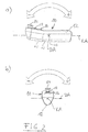
- Fig. 1 shows in a simplified schematic perspective view of a handset 10 of a radio remote control for a machine.
- a machine devices are understood to have moving components that can be changed by appropriate control in their respective situation. It is particularly intended for the remote control of cranes, boom of concrete pumps, hydraulically powered loading bridges on trucks and the like.
- the handset 10 comprises in its housing 12 at least one sensor, not shown, by means of which movements of the handset 10 in space can be detected.
- the motion sensor or the motion sensors can or can detect rotational movements about a rotational or tilting axis DA and tilting movements about a tilting axis KA.
- the detection of the movements of the Handset 10 can be done by means of appropriate angle and position sensors.
- the position or movement sensors used react to gravity or gravitational attraction and therefore have an angle-dependent resolution or maximum signal strength depending on the rotational or tilting movement of the hand-held device.
- the output signal may be maximum at deflection about the horizontal and increasingly be close to zero when turning or tilting in the vertical.
- the hand-held device shown purely by way of example here can have a type of joystick 14, which can generally be operated with a thumb of a user's hand in order to remotely control corresponding machine parts.
- two operation buttons 16, 18 are shown, which can be actuated to activate further control options.
- One of these operating buttons 16, 18 can be used, for example, to activate a movement operating mode in which movements detected by the motion sensors, not shown, are actually converted into control commands in order to be able to control the machine as a function of performed movements.
- This button can be assigned in the manner of a flip-flop circuit on re-pressing and switching off this motion mode of operation. Alternatively, the switching on or off can be done via different control buttons.
- On a handset 10 may also be provided an emergency stop switch, which is not shown in the present example, however.
- the hand-held device shown is purely exemplary and can be configured differently both with regard to its external shape and with regard to further or other operating elements.
- the handset 10 can be rotated or pivoted about its axis of rotation DA (tilt axis), which is indicated by the double arrow. Furthermore, the handset 10 (FIG. Fig. 2 b) ) can also be tilted or pivoted about its tilt axis KA, which is also indicated by the double arrow.
- the movements about the axis of rotation DA or Tilting axis KA are detected by the motion sensor (s) and, when the motion operating mode is activated accordingly, converted into control signals, which are transmitted to the machine to be remotely controlled.
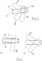
- Fig. 3 shows a schematic rectangular representation different positions of movement of the handset 10 about its axis of rotation DA.
- a current position I of the handset 10 in space can be assumed as the reference position. How out Fig. 3 can be seen, this reference position I slightly inclined in the example to a horizontal. A comfortable position of such a handheld device is usually in an angular range of +/- 20 ° around the horizontal.
- a so-called movement operating mode for example by pressing an actuating button 16 or 18 (FIG. Fig. 1 )
- the current position I of the handset 10 detected in space and adopted as a reference position for the subsequent motion detection.
- Rotary or pivotal movements of the handset 10 about the axis of rotation DA in positions II and III can then be evaluated with reference to the reference position I and converted into control commands, which are transmitted to the machine to be remotely controlled.
- the movement position IV illustrates a position of the handset 10 in which a maximum angle of rotation has been exceeded with respect to the reference position I.
- the generation of control commands due to the detected movements can be interrupted (termination of the motion mode).
- IV can be achieved, for example, when a user, who holds the handset 10 in his hand while angling his arm, stretches it down so that the handset is oriented substantially vertically toward the ground.
- Fig. 4 shows in the sub-figures a) and b) another type of control or another control mode.
- the handset must first be brought into a movement position II or II ', which corresponds approximately to a preset reference position I of the hand-held device 10.
- the movements of the hand-held device then detected are again converted into control commands, which can be transmitted to the machine. This is in Fig. 2 b) indicated by the movement positions III and V.
- Switching off the motion mode of operation, so that the detected movements are no longer converted into control commands can be done by operating a control knob 16, 18 on the handset 10 or, as above with reference to the Fig. 3 described by leaving a predetermined angle range and the handset is brought, for example, in the movement position IV.
- Fig. 5 shows a simplified flowchart for a control according to Fig. 3 , in which a current position in space is determined as the reference position.
- a control unit which is normally housed in the housing 12 of the handset 10, whether the motion mode is turned on, for example by pressing a button on the operation buttons 16, 18.
- the current position (see I in Fig. 3 ) of the handset in the room as a reference position determined (step 22).
- step 24 the current position is detected and set in relation to the reference position I.
- An action is taken at step 26 Inquire whether the motion mode has been turned off.
- step 28 it is checked in step 28 whether the movement of the handset has taken place within a predetermined turning / tilting range. If the spin / tilt region has been left (N), the motion mode is turned off in step 34 and, if applicable, a user detectable signal is generated on the handset 10. If the movement is within the turning / tilting range (J) in step 28, a control command calculated as a function of the detected movement is generated in step 30 and transmitted to the machine to be remotely controlled or to a machine component to be driven. The steps 24-30 are usually repeated several times in succession with the motion operating mode switched on in order to be able to detect continuously changing movement positions of the handheld device 10 and to be able to generate corresponding control commands. This loop is indicated by the arrow 31.
- the handset also comprises an output means, not shown in the figures, which is arranged to generate, in response to sensed movements, at least one output perceptible to the user, in particular an optical and / or audible and / or haptic signal on the handset.
- an output means not shown in the figures, which is arranged to generate, in response to sensed movements, at least one output perceptible to the user, in particular an optical and / or audible and / or haptic signal on the handset.
- This step 32 extends the multiple sweep loop of steps 24-32, which is indicated by the dashed arrows 33, circumventing the arrow 31.
- a perceptible for the user signal By generating a perceptible for the user signal can during the one Winkelaustsch generating Rotational or tilting movement of the handset 10 and the control command thus generated the user audibly or tactile or visually perceptible feedback can be given, which gives a subjectively experienced by the user control security, such as this by remote control by joystick or push buttons or the like knows and was used to.
- the generation of a perceptible for the user signal can, for. B. when leaving the reference position and when reaching a first stage, which corresponds for example to a speed of the machine part to be remotely controlled.
- a second stage of a speed control fast speed
- speed level II is left again and returned to level I, this can also be made perceptible to the user by means of a corresponding signal.
- the user perceivable signal is haptically and / or acoustically configured, the user may be visually focused on the remote components of the machine when remotely controlling the machine and is not required to direct his gaze to the handset 10.
- the movements he makes with the handset 10 are brought to his perception by acoustic or / and haptic signals in a kind of feedback so that he can perform further movements or countermovements with the handset 10 according to the sensed signals to the desired Remote control of the machine to make.
- such signals can also be output in proportion to the detected movements. It is conceivable, for example, that this makes the enlargement or reduction of the detected turning or tilting angle acoustically / haptically tangible, it being entirely possible for a different signal to be output for the enlargement of the angle than for the reduction of the angle. If the handset is held steady in a certain angular position, the corresponding signal will not be output, but only when the handset is set in motion. Alternatively, it is conceivable that an acoustic and / or haptic signal is output constantly during the entire movement operating mode and is preferably also configured proportionally to the detected rotational or tilting angle.
- the proportional output of a user perceivable signal is not limited to a direct proportional dependence between sensed motion and signal strength. Rather, it is also thought of a logarithmic signal distribution, which is better suited for human perception.
- Both the acoustic and the haptic or vibration feedback signal can consist of vibration impulses or short burst chains of vibration impulses, for example, whose spacing decreases as the rotational or tilting angle increases and thus their perceived intensity increases.
- An acoustic and / or haptic and / or optical output on the handset can also be output when the reference position is reached or when a shutdown situation is reached, for example, when reaching angles of about +/- 45 ° with respect to the reference position.
- the handset 10 includes a return receiver, which is adapted to receive feedback information from the machine to be controlled, in which case it is assumed that such feedback information sending return message transmitter is provided on the machine.
- the receiving device on the machine may comprise a check-back transmitter which acknowledges the receipt of control commands, so that the feedback information is confirmation of the receipt of control commands. If these expected radio reception acknowledgments are not registered by the handset 10, a respective output means of the handset 10 may alert the user to any trouble.
- this has a data on the respective actual position of the movable machine part and / or on the motion state detecting sensor device - and the data of this sensor device as feedback information sending feedback to the machine, wherein the feedback receiver of Handellas receive this feedback information and can pass it to the control unit.
- the latter can then according to a variant of the invention modify control commands for the machine in dependence on the received feedback information.
- the output means can be designed in the form of a display device so that they represent the respective actual position and / or the current deviation of the actual position of the determined by the current position of the handset target position and / or the speed of movement of the movable machine part , Also in this regard is an optical and / or acoustic and / or haptic display or output in question.
Description
Die vorliegende Erfindung betrifft eine Funkfernsteuerung eines Krans, eines Auslegers, einer Ladebrücke und/oder eines Hebezeugs mit verschiedenen beweglichen Bauteilen (Maschine) mit wenigstens einem durch die Funkfernsteuerung ansteuerbaren Maschinenantrieb eines beweglichen Maschinenteils, umfassend eine der Maschine zugeordnete Funkempfangseinrichtung, ein Handgerät mit einer Steuereinheit, einer Sendeeinrichtung und wenigstens einem Bewegungssensor, wobei die Steuereinheit dazu eingerichtet ist, durch einen Benutzer hervorgerufene Steuerbefehle an die Sendeeinrichtung zu übermitteln und die Sendeeinrichtung zum Übertragen der Steuerbefehle an die Empfangseinrichtung zu veranlassen, und wobei mittels des Bewegungssensors Bewegungen des Handgeräts im Raum um wenigstens eine Kipp- bzw. Neigeachse (KA, DA) erfassbar sind, derart, dass in einem Bewegungsbetriebsmodus die erfassten Bewegungen durch die Steuereinheit in Steuerbefehle umwandelbar sind, welche an die Maschine durch Funkübertragung zwischen Sendeeinrichtung und Empfangseinrichtung übermittelbar sind, wobei der Bewegungsbetriebsmodus durch eine benutzerseitige Eingabe am Handgerät aktivierbar ist.The present invention relates to a radio remote control of a crane, a boom, a loading bridge and / or a hoist with various moving components (machine) with at least one controllable by the radio remote machine drive a movable machine part, comprising a machine associated with the radio receiving device, a handset with a control unit , a transmitting device and at least one motion sensor, wherein the control unit is adapted to transmit control commands caused by a user to the transmitting device and to cause the transmitting device for transmitting the control commands to the receiving device, and wherein by means of the motion sensor movements of the handset in the room by at least a tilting or tilting axis (KA, DA) can be detected, such that in a movement operating mode the detected movements can be converted by the control unit into control commands which are sent to the machine by F unkübertragung between transmitting device and receiving device can be transmitted, wherein the movement mode of operation can be activated by a user input on the handset.
Besonders bevorzugtes, wenngleich nicht ausschließliches Anwendungsfeld der vorliegenden Erfindung ist die Steuerung von Kranen und Hebezeugen. Im Beispielsfalle eines Auslegerkrans, etwa eines Baukrans, können z.B. die Orientierung des Auslegers (Drehwinkel), die Bewegung der Katze und die Bewegung des Hakens mit einer entsprechend ausgestalteten Funkfernsteuerung nach der Erfindung gesteuert werden.A particularly preferred although not exclusive field of application of the present invention is the control of cranes and hoists. In the example of a jib crane, such as a construction crane, e.g. the orientation of the boom (rotation angle), the movement of the cat and the movement of the hook are controlled with a suitably designed radio remote control according to the invention.
Die Ansteuerung von Geräten über Lagesensoren in einer Fernbedienung bzw. einem einer Fernbedienung ähnlichen Bauteil ist bekannt. Es wird beispielsweise auf Spielekonsolen oder Ähnliches hingewiesen. Lagesensoren werden heute beispielsweise auch in mobile Telefone eingebaut, so dass die Ausrichtung eines solchen Geräts, insbesondere dessen Display ermittelt werden kann, um die Anzeige im Display entsprechend der Ausrichtung des Geräts anzupassen.The control of devices via position sensors in a remote control or a similar remote control component is known. It is pointed out, for example, on game consoles or the like. Position sensors are also installed today, for example, in mobile phones, so that the orientation of such a device, in particular its display can be determined to adjust the display in the display according to the orientation of the device.
Entsprechende hinsichtlich der vorliegenden Erfindung nicht gattungsgemäße Funkfernsteuerungen sind aus der
Die
Die
Die
Um eine Funkfernsteuerung für eine Maschine optimal einsetzen zu können, ist es erforderlich, dass Bewegungen des Handgeräts im Raum präzise erfasst werden können. Ferner ist darauf zu achten, dass die Funkfernsteuerung mittels des Handgeräts eine für einen Benutzer intuitive Maschinensteuerung ermöglicht, insbesondere wenn der Benutzer die Maschine durch Bewegung des Handgeräts bedienen soll.In order to optimally use a radio remote control for a machine, it is necessary that movements of the handheld device in the room can be detected precisely. Furthermore, care must be taken that the radio remote control by means of the handset allows a user-intuitive machine control, especially if the user is to operate the machine by moving the handset.
Aufgabe der Erfindung ist es, eine gattungsgemäße Funkfernsteuerung im Hinblick auf eine intuitive Bedienung durch einen Benutzer zu verbessern. Hierzu wird vorgeschlagen, dass die Empfangseinrichtung einen Rückmeldesender aufweist und dazu eingerichtet ist, bei Empfang von Steuerbefehlen den Rückmeldesender zur Sendung von Rückmeldeinformationen zu aktivieren, und wobei das Handgerät einen zum Empfang der Rückmeideinformationen eingerichteten und mit der Steuereinheit verbundenen Rückmeldeempfänger sowie eine von der Steuereinheit gesteuerte akustische und/oder haptische Anzeigeeinrichtung aufweist, mittels welcher Betriebsfunktionsinformationen der Funkfernsteuerung nach Maßgabe des Empfangs von Rückmeldesignalen von dem Rückmeldesender anzeigbar sind.The object of the invention is to improve a generic radio remote control in terms of intuitive operation by a user. For this purpose, it is proposed that the receiving device has a feedback transmitter and is adapted to activate the feedback transmitter for the transmission of feedback information upon receipt of control commands, and wherein the handset set up for receiving the return information and connected to the control unit feedback receiver and controlled by the control unit having acoustic and / or haptic display device by means of which operating function information of the radio remote control in accordance with the reception of feedback signals from the feedback transmitter can be displayed.
Bei einer derartigen Ausgestaltung der Steuereinheit ist es möglich, die aktuelle Referenzlage in einer für einen Benutzer angenehmen Handstellung zu ermitteln. Ein Handgerät einer Funkfernsteuerung wird oftmals nicht exakt horizontal gehalten, sondern eine natürliche Haltung der menschlichen Hand führt dazu, dass das Handgerät mit einer leichten Neigung in Richtung nach oben gehalten wird. Diese natürliche Haltung kann dann als aktuelle Refe - renzlage bzw. als eine Art Neutralposition festgelegt werden, so dass durch den Bewegungssensor erfasste Bewegungen, wie etwa Drehen, Neigen oder Kippen des Handgeräts, erfasst und in Steuerbefehle umgewandelt werden können. Ausgehend von einer solchen natürlichen Stellung der menschlichen Hand ergibt sich auch eine optimale Ausnutzung der möglichen Bewegungen durch den Benutzer zwecks Steuerung eines entsprechenden Maschinenantriebs.In such an embodiment of the control unit, it is possible to determine the current reference position in a comfortable hand position for a user. A handset of a radio remote control is often not kept exactly horizontal, but a natural attitude of the human hand causes the handset is held with a slight inclination in the upward direction. This natural posture can then be defined as the current reference position or as a kind of neutral position, so that movements detected by the motion sensor, such as turning, tilting or tilting of the handset, can be detected and converted into control commands. Based on such a natural position of the human hand also results in an optimal utilization of the possible movements by the user for the purpose of controlling a corresponding machine drive.
Bevorzugt wird vorgeschlagen, dass die Funkfernsteuerung derart eingerichtet ist, dass bei Aktivierung des Bewegungsbetriebsmodus die aktuelle Lage des Handgeräts im Raum erfasst wird und mit einer vorgegebenen Referenzlage verglichen wird, und dass erfasste Bewegungen erst dann als Steuerbefehle an die Maschine übermittelbar sind, wenn die Funkfernsteuerung wenigstens näherungsweise in die vorgegebene Referenzlage ge - bracht worden ist, wobei zur Erzeugung von Steuerbefehlen Bewegungen relativ zur vorgegebenen Referenzlage erfasst werden.Preferably, it is proposed that the radio remote control is set up such that upon activation of the motion mode, the current position of the handset is detected in space and compared with a predetermined reference position, and that detected movements are only as control commands to the machine can be transmitted, if the radio remote control has been brought at least approximately in the predetermined reference position, wherein for the generation of control commands movements are detected relative to the predetermined reference position.
Die vorgegebene Referenzlage kann beispielsweise eine im Wesentlichen horizontale Ausrichtung des Handgeräts im Raum sein. Diese vorgegebene Referenzlage muss ausgehend von einer Lage des Handgeräts im Raum, in welcher die Bewegungssteuerung aktiviert wird, erreicht bzw. eingestellt werden. Sobald das Handgerät in eine aktuelle Lage gebracht worden ist oder sich beim Aktivieren der Bewegungssteuerung bereits befindet, welche etwa der vorgegebenen Referenzlage entspricht, d. h. diese vorgegebene Referenzlage innerhalb eines Toleranzbereichs trifft, werden dann ausgehend von der vorgegebenen Referenzlage weitere Bewegungen des Handgeräts erfasst und in Steuerbefehle umgewandelt, die an die Maschine übermittelt werden können.The predetermined reference position may be, for example, a substantially horizontal orientation of the handset in space. This predetermined reference position must be reached or adjusted starting from a position of the handset in the room in which the motion control is activated. Once the handset has been brought into a current position or is already in activating the motion control, which corresponds approximately to the predetermined reference position, d. H. meets this predetermined reference position within a tolerance range, then further movements of the handset are detected based on the predetermined reference position and converted into control commands that can be transmitted to the machine.
Alleine oder mit der zuvor genannten Weiterbildung ermöglicht die Erfindung eine intuitive Bedienung und Steuerung einer Maschine mittels eines Handgeräts, das Bewegungssensoren enthält und dessen Steuereinheit eine Übermittlung von erfassten Bewegungen als Steuerbefehl an die Maschine ermöglicht.Alone or with the aforementioned development, the invention allows intuitive operation and control of a machine by means of a hand-held device that contains motion sensors and whose control unit allows transmission of detected movements as a control command to the machine.
Es sei diesbezüglich auf zwei verschiedene Steuerungsbetriebsmöglichkei - ten hingewiesen, die in betreffenden Ausführungsformen einer Funkfernsteuerung nach der vorliegenden Erfindung realisiert sein können. Bei einer ersten Steuerungsbetriebsweise erfolgt die Aktivierung des Bewegungsbetriebsmodus durch Betätigung eines Schalters. Hierdurch wird vorzugsweise ein etwaig vorhandenes sicherheitsrelevantes Relais oder dgl. der Maschine freigeschaltet und es folgt die Referenzierung des Handgerätes entsprechend einer der vorgenannten Referenzierungsmöglichkeiten. Durch Bewegen des Handgerätes relativ zu der erfassten Referenzlage erfolgt dann die Vorgabe der zu steuernden Bewegung des Maschinenteils, wobei durch entgegengesetzte Bewegungsrichtungen des Handgerätes relativ zur Referenzlage Steuerbefehle erzeugt werden können, die auch das Maschinenteil zur Bewegung in entsprechend entgegengesetzten Richtungen veranlassen. Durch die Amplitude der Bewegung des Handgerätes relativ zur Referenzlage kann dann auch der Betrag der zu steuernden Bewegung, also etwa der Geschwindigkeitsbetrag oder Beschleunigungsbetrag vorgegeben werden. Ein Beispiel hierfür ist zum Beispiel dadurch gegeben, dass durch Verdre - hen des Handgerätes relativ zu einer bei Einschaltung des Bewegungsbetriebsmodus erfassten Referenzlage um z.B. +/-30° sowohl die Richtung als auch der Betrag der zu steuernden Bewegung des Maschinenteils vorgegeben wird, wobei der Plus-Bereich eine Bewegungsrichtung und der Minus-Bereich die entgegengesetzte Bewegungsrichtung des Maschinenteils darstellt.In this regard, reference should be made to two different control operation possibilities that may be implemented in respective embodiments of a radio remote control according to the present invention. In a first control mode, the activation of the motion mode is performed by operating a switch. As a result, preferably any existing safety relay or the like. The machine is unlocked and it follows the referencing of the handset according to one of the aforementioned referencing options. By moving the handset relative to the detected reference position is then the specification of the controlled movement of the machine part, whereby by opposite directions of movement of the handset relative to the reference position control commands can be generated, which also cause the machine part to move in corresponding opposite directions. By the amplitude of the movement of the handset relative to the reference position The amount of the movement to be controlled, for example the speed amount or the acceleration amount, can then also be specified. An example of this is provided, for example, by specifying both the direction and the amount of the movement of the machine part to be controlled by rotating the handset relative to a reference position detected when the motion mode is activated by +/- 30 °, for example Plus area represents a direction of movement and the minus area represents the opposite direction of movement of the machine part.
Eine zweite Steuerungsbetriebsweise sieht vor, dass z.B. zwei Kontakte bzw. Drucktasten vorgesehen sind, die zur Aktivierung des Bewegungsbetriebsmodus zu betätigen sind, wobei eine der Tasten einer Bewegungsrichtung des Maschinenteils zugeordnet ist, wohingegen die andere Taste der entgegengesetzten Bewegungsrichtung des Maschinenteils zugeordnet ist. Die Bewegung des Handgerätes relativ zur betreffenden Referenzlage würde dann z.B. nur den Betrag der zu steuernden Geschwindigkeit des Maschinenteils vorgeben.A second control mode provides that e.g. two contacts or push buttons are provided, which are to be actuated to activate the movement mode of operation, wherein one of the keys associated with a direction of movement of the machine part, whereas the other button is associated with the opposite direction of movement of the machine part. The movement of the handset relative to the respective reference position would then be e.g. specify only the amount of the controlled speed of the machine part.
Zur benutzerseitigen Eingabe können am Handgerät z.B. Tastschalter vorgesehen sein. So ist gemäß einer Ausführungsform der Erfindung der Bewegungsbetriebsmodus durch Betätigung eines Schalters am Handgerät auszulösen und durch fortgesetzte Berührung dieses Schalters aufrechtzuerhalten, um die Bewegung des Maschinenteils steuern zu können. Ein Loslassen dieses Schalters führt dann dazu, dass keine weiteren Steuerungsbefehle zur Steuerung der Bewegung des Maschinenteils übertragen werden. Es handelt sich hierbei also um eine Art Totmann-Schaltung.For user input, e.g. Tastschalter be provided. Thus, according to one embodiment of the invention, the motion mode of operation is triggered by actuation of a switch on the handset and maintained by continued contact of that switch to control the movement of the machine part. Releasing this switch will then result in no further control commands being transmitted to control the movement of the machine part. It is therefore a kind of deadman circuit.
Gemäß einer anderen Ausführungsform der Erfindung sind einrastende Schalter für benutzerseitige Eingabe am Handgerät vorgesehen, mittels welcher der Benutzer den Bewegungsbetriebsmodus durch einen aktiven Umschaltvorgang an einem solchen Rastschalter aktivieren kann.According to another embodiment of the invention, latching switches are provided for user input on the handset, by means of which the user can activate the movement mode of operation by an active switching operation on such a latching switch.
Die für den Benutzer des Handgeräts wahrnehmbare Ausgabe verbessert die intuitive ferngesteuerte Bedienung einer Maschine. Insbesondere durch die akustischen oder/und haptischen Signalen wird der Benutzer auf intuitive Weise bei der Maschinenbedienung mittels Bewegungen des Handgeräts unterstützt werden. Durch die Ausgabe erfolgt eine Art Rückkopplung zum Benutzer, so dass die Mensch-Maschine-Schnittstelle optimiert werden kann.The output perceivable to the user of the handset improves the intuitive remote control of a machine. In particular, by the acoustic and / or haptic signals, the user will be supported in an intuitive way in the machine operation by means of movements of the handset. The output is a kind of feedback to the user, so that the human-machine interface can be optimized.
Hierzu wird insbesondere vorgeschlagen, dass die Ausgabemittel derart eingerichtet sind, dass die für den Benutzer wahrnehmbare Ausgabe abhängig von durch den Bewegungssensor ausgegebenen Signalen erzeugt wird.For this purpose, it is in particular proposed that the output means are set up such that the output perceptible to the user is generated as a function of signals output by the motion sensor.
Das Ausgabemittel kann derart eingerichtet sein, dass die für den Benutzer wahrnehmbare Ausgabe stufenartig abhängig vom Erreichen von vom Bewegungssensor ausgegebenen bestimmten Signalstärken erzeugt wird. Hierdurch ist es beispielsweise möglich, das Verlassen der Referenzlage anzuzeigen und bei Erreichen einer bestimmten Relativlage im Raum ein weiteres Signal anzugeben, mittels welchem das Erreichen einer ersten Bewegungs- bzw. Steuerungsstufe angegeben wird. Ein weiteres Signal könnte beispielsweise ausgegeben werden, wenn ein Extremwert der möglichen Bewegung erreicht wird.The output means may be arranged to generate the output perceptible to the user in a stepwise manner in response to the achievement of certain signal strengths output by the motion sensor. As a result, it is possible, for example, to indicate leaving the reference position and, upon reaching a certain relative position in space, to specify a further signal by means of which the achievement of a first movement or control level is indicated. For example, another signal could be output when an extreme value of the possible motion is reached.
Alternativ kann das Ausgabemittel derart eingerichtet sein, dass die für den Benutzer wahrnehmbare Ausgabe proportional zur vom Bewegungssensor ausgegebenen Signalstärke erzeugt wird. Hier wird insbesondere daran ge - dacht, dass ausgehend von einer Referenzlage ein zunehmendes Neigen bzw. Kippen in eine Richtung durch ein sich verstärkendes akustisches oder/und haptisches Signal repräsentiert wird, so dass der Benutzer aufgrund dieser Ausgabe erfahren und bewerten kann, in welcher aktuellen Lage er das Handgerät relativ zur erfassten bzw. vorgegebenen Referenzlage hält.Alternatively, the output means may be arranged to generate the output perceptible to the user in proportion to the signal strength output by the motion sensor. Here, it is especially thought that, starting from a reference position, increasing tilting or tilting in one direction is represented by an amplifying acoustic and / or haptic signal, so that the user can learn and evaluate in which current situation Location he holds the handset relative to the detected or predetermined reference position.
Die für den Benutzer wahrnehmbare Ausgabe kann einer vorbestimmten Kennlinie entsprechend in Abhängigkeit von der vom Bewegungssensor ausgegebenen Signalstärke erzeugt werden. Der Kennlinienverlauf kann je nach Steuerungsart optimiert sein, so dass die Abhängigkeit der für den Benutzer wahrnehmbaren Ausgabe von der vom Bewegungssensor ausgegebenen Signalstärke direkt proportional, also linear, oder degressiv oder pro - gressiv ist. Insbesondere kommt auch eine logarithmische Kennlinie in Frage.The output perceptible to the user may be a predetermined one Characteristic are generated in accordance with the signal strength output by the motion sensor. The characteristic curve can be optimized depending on the type of control, so that the dependence of the output perceptible on the user of the signal strength output by the motion sensor is directly proportional, ie linear, or degressive or progressive. In particular, a logarithmic characteristic also comes into question.
Gemäß einer bevorzugten Ausgestaltung der Erfindung erfolgt die für den Benutzer wahrnehmbare Ausgabe des wenigstens einen Ausgabemittels differentiell, also nur dann, wenn sich die vom Bewegungssensor ausgegebene Signalstärke ändert. Eine solche differentielle oder dynamische Ausgabe bietet dem Benutzer normalerweise ein ausreichendes subjektives Rückkopplungsgefühl der Funkfernsteuerung und belastet im Mittel die Stromversorgung des Handgerätes vergleichsweise gering, da während der Phasen konstanter Signalausgabe des Bewegungssensors das Ausgabemittel nicht aktiviert sein muss. Gemäß einer Variante der Erfindung ist es vorgesehen, dass hinsichtlich der Erzeugung der für den Benutzer wahrnehmbaren Ausgabe zwischen vorstehend genannten Betriebsmodi umgeschaltet werden kann, so z.B. zwischen einem differentiellen Modus und einem statisch-proportionalen Modus.According to a preferred embodiment of the invention, the perceptible for the user output of at least one output means is differentially, so only when the signal strength output by the motion sensor changes. Such a differential or dynamic output normally provides the user with a sufficient subjective feedback feeling of the radio remote control and, on average, places a relatively small burden on the power supply of the handset since during the phases of constant signal output of the motion sensor the output means need not be activated. According to a variant of the invention, it is provided that with regard to the generation of the output perceptible to the user, it is possible to switch between the above-mentioned operating modes, e.g. between a differential mode and a statically-proportional mode.
Die Steuereinheit ist vorzugsweise derart eingerichtet, dass durch den bzw. einen Bewegungssensor erfasste Bewegungen in einem Arbeitsdreh- bzw. Kippbereich von maximal etwa -45° bis +45°, insbesondere -30° bis +30°, um eine zugehörige horizontale Dreh- bzw. Kippachse in Steuerbefehle für die Maschine umgewandelt werden. Eine derartige Begrenzung des in Steuerbefehle für die Maschine umwandelbaren Bewegungsbereichs dient einerseits einer ergonomischen Handhabung des Handgeräts, da mittels der menschlichen Hand Bewegungen in einem größeren Winkelbereich unbequem sind. Ferner kann ein derart definierter Winkelbereich auch dazu die - nen, Stellungen des Handgeräts festzulegen, bei welchen die Bewegungssteuerung mittels des Handgeräts ausgeschaltet wird und keine weiteren Steuerbefehle mehr an die Maschine aufgrund von erfassten Bewegungen gesendet werden. Hierzu wird insbesondere vorgeschlagen, dass das Ausgabemittel derart eingerichtet ist, dass es eine Annäherung an die maximale Dreh- bzw. Kippbewegung oder/und ein Verlassen des Arbeitsdreh- bzw. Kippbereichs durch eine entsprechende für den Benutzer wahrnehmbare Ausgabe anzeigt.The control unit is preferably set up in such a way that movements detected by the movement sensor or a movement sensor in a working rotation or tilting range of a maximum of about -45 ° to + 45 °, in particular -30 ° to + 30 °, cause an associated horizontal rotation or tilting movement . Tilting axis are converted into control commands for the machine. Such a limitation of the range of motion convertible into control commands for the machine serves, on the one hand, for ergonomic handling of the handheld device since movements in a larger angular range are inconvenient by means of the human hand. Furthermore, an angular range defined in this way can also be used to define positions of the handheld device in which the motion control is switched off by means of the handheld device and no further ones Control commands are sent to the machine more due to detected movements. For this purpose, it is in particular proposed that the output means is set up in such a way that it indicates an approximation to the maximum rotational or tilting movement and / or leaving the working rotary or tilting range by a corresponding output perceptible to the user.
Weiterbildend kann die Steuereinheit derart eingerichtet sein, dass beim Verlassen des Arbeitsdreh- bzw. Kippbereichs bis auf Weiteres keine weiteren Steuerbefehle aufgrund von erfassten Bewegungen erzeugt werden. Gemäß einer Variante der Erfindung können jedoch sicherheitsrelevante Steuerbefehle, z.B. Stopp-Befehle, vom Handgerät zur Maschine gesendet werden, wenn der Arbeitsdreh- bzw. Kippbereich verlassen wird. In diesem Zusammenhang wird darauf hingewiesen, dass das Verlassen eines bevorzugten Winkel- bzw. Bewegungsbereichs sich vorzugsweise nur auf die Maschinensteuerung mittels Bewegung des Handgeräts auswirkt, jedoch nicht auf die Ansteuerung der Maschine mittels etwaiger sonstiger Bedienelemente am Handgerät, wie etwa Druckknöpfe, Joystick oder dgl. Ferner wird auch darauf hingewiesen, dass beim Verlassen des Arbeitsdreh- bzw. Kippberreichs in der Maschinensteuerung festgelegt wird, ob die Maschine dann in ihrem aktuellen Zustand verharrt oder in eine Neutralstellung gebracht wird. Es ist ferner auch festzulegen, ob die Bewegungen aller durch die Funkfernsteuerung ansteuerbaren Maschinenteile im Falle des Verlassens des Arbeitsdreh- bzw. Kippbereichs gestoppt werden sollen oder ob nur diejenigen Antriebe, welche durch die Bewegungssteuerung explizit angesteuert werden, gestoppt werden. Derartige Bedienkonzepte können unter Berücksichtigung von entsprechenden Sicherheitskonzepten und -normen festgelegt werden.In a further development, the control unit can be set up in such a way that no further control commands due to detected movements are generated when leaving the work turning or tilting area until further notice. However, according to a variant of the invention, safety-related control commands, e.g. Stop commands are sent from the handset to the machine when the working turn or tilt range is exited. In this connection, it should be noted that leaving a preferred angular range or movement range preferably affects only the machine control by means of movement of the handset, but not the activation of the machine by means of any other controls on the handset, such as push buttons, joystick or the like Furthermore, it is also pointed out that when leaving the working rotation or tilting range in the machine control it is determined whether the machine will then remain in its current state or be brought into a neutral position. It is also to be determined whether the movements of all controllable by the radio remote machine parts in the case of leaving the Arbeitsdreh- or tilting should be stopped or whether only those drives which are controlled by the motion control, stopped. Such operating concepts can be determined taking into account corresponding security concepts and standards.
Gemäß einer bevorzugten Weiterbildung der Erfindung weist die Empfangseinrichtung einen Rückmeldesender auf und ist dazu eingerichtet, bei Empfang von Steuerbefehlen den Rückmeldesender zur Sendung von Rückmeldeinformationen zu aktivieren, wobei das Handgerät einen zum Empfang der Rückmeldeinformationen eingerichteten und mit der Steuereinheit verbundenen Rückmeldeempfänger aufweist. Die Empfangseinrichtung mit Rückmeldesender und die Sendeeinrichtung des Handgerätes mit Rückmeldeempfänger bilden somit ein bidirektionales Funkfernsteuersystem mit verbesserten Sicherheitsmerkmalen. Vorzugsweise hat das Handgerät eine von der Steuereinheit gesteuerte akustische oder/und optische oder/und haptische Anzeigeeinrichtung, mittels welcher Betriebsfunktionsinformationen der Funkfernsteuerung nach Maßgabe des Empfangs von Rückmeldesignalen von dem Rückmeldesender anzeigbar sind. Eine solche Anzeigeeinrichtung stellt somit ein Ausgabemittel dar, welches den Benutzer über Störungen informieren kann. Dem Aspekt der Funkrückmeldung, insbesondere in Kombination mit der vorstehend genannten Anzeigeeinrichtung und den Merkmalen des Oberbegriffs des Anspruchs 1 kommt gegebenenfalls selbständige erfinderische Bedeutung zu, und der Anmelder behält sich vor, einen entsprechenden selbständigen Patentanspruch aufzustellen.According to a preferred embodiment of the invention, the receiving device has a feedback transmitter and is configured to activate the feedback transmitter for the transmission of feedback information upon receipt of control commands, wherein the handset for receiving the Having feedback information set up and connected to the control unit feedback receiver. The receiving device with feedback transmitter and the transmitting device of the handset with feedback receiver thus form a bidirectional radio remote control system with improved security features. Preferably, the handset has an audible and / or optical and / or haptic display device controlled by the control unit, by means of which operating function information of the radio remote control in accordance with the reception of feedback signals can be displayed by the feedback transmitter. Such a display device thus represents an output means which can inform the user about faults. The aspect of the radio feedback, in particular in combination with the aforementioned display device and the features of the preamble of claim 1 is possibly independent inventive importance, and the applicant reserves the right to make a corresponding independent claim.
Ein weiterer vorteilhafter Erfindungsaspekt ist durch die Merkmale des Anspruchs 5 gegeben, nämlich dass eine Daten über die jeweilige Ist-Position des beweglichen Maschinenteils oder/und über dessen Bewegungszustand erfassende Sensoreinrichtung - und ein die Daten dieser Sensoreinrichtung als Rückmeldeinformationen sendender Rückmeldesender an der Maschine vorgesehen ist, und dass das Handgerät einen zum Empfang der Rückmeldeinformationen eingerichteten und mit der Steuereinrichtung verbundenen Rückmeldeempfänger aufweist. Vorzugsweise weist das Handgerät hierzu eine von der Steuereinheit gesteuerte, die jeweilige Ist-Position oder/und die aktuelle Abweichung der Ist-Position von der durch die momentane Lage des Handgerätes bestimmten Soll-Position oder/und die Bewegungsgeschwindigkeit des beweglichen Maschinenteils darstellende optische oder/und akustische oder/und haptische Anzeigeeinrichtung auf. Diese Anzeigeeinrichtung kann den Benutzer daher über die jeweilige Lage, Bewe - gungsrichtung und Bewegungsgeschwindigkeit des Maschinenteils informieren. Vorzugsweise umfasst die Anzeigeeinrichtung ein Display, z.B. LCD-Display, auf dem die Informationen graphisch als Bilder bzw. Piktogramme oder Videos oder/und numerisch als Ziffern und Buchstaben darstellbar sind.A further advantageous aspect of the invention is given by the features of claim 5, namely that a data on the respective actual position of the movable machine part and / or on the movement state detecting sensor device - and the data of this sensor device as a feedback information sending feedback message is provided on the machine , and that the handset has a set up to receive the feedback information and connected to the control device feedback receiver. For this purpose, the hand-held device preferably has an optical unit controlled by the control unit, the respective actual position and / or the actual deviation of the actual position from the desired position determined by the current position of the hand-held device and / or the optical speed of the moving machine part. and acoustic and / or haptic display device. This display device can therefore inform the user about the respective position, direction of movement and speed of movement of the machine part. Preferably, the display device comprises a display, eg LCD display, on which the information is displayed graphically as pictures or pictograms or videos or / and numerically representable as numbers and letters.
Aufgrund der so erfassten Ist-Werte kann die vorgegebene Referenzlage bei der Ausführungsform der Funkfernsteuerung gemäß Anspruch 2 z.B. bei jedem Einschaltvorgang der Steuerung jeweils aktuell in Abhängigkeit von der momentanen Lage des beweglichen Maschinenteils bestimmt werden. Bei einer solchen Ausführungsform fragt das Handgerät zunächst die Rückmeldeinformationen von dem Rückmeldesender an der Maschine ab, bevor es neue Steuerbefehle aussendet.Due to the thus-detected actual values, the predetermined reference position in the embodiment of the radio remote control according to claim 2 can be e.g. each time the controller is switched on, each time it is determined as a function of the instantaneous position of the movable machine part. In such an embodiment, the handset first interrogates the feedback information from the acknowledgment transmitter on the machine before sending out new control commands.
Ferner ist es gemäß einer Variante der Funkfernsteuerung nach der Erfindung vorgesehen, dass die Steuereinheit dazu eingerichtet ist, Steuerbefehle für die Maschine in Abhängigkeit von den empfangenen Rückmeldeinformationen zu modifizieren. Ein Beispiel hierfür könnte es sein, dass bei Annäherung des beweglichen Maschinenteils an seine Soll-Position eine auto - matische Herabsetzung der Geschwindigkeit des Maschinenteils oder/und eine größere Auflösung der Steuercharakteristik im Sinne einer feinfühlige - ren Steuerung erfolgt.Furthermore, according to a variant of the radio remote control according to the invention, it is provided that the control unit is set up to modify control commands for the machine as a function of the received feedback information. An example of this could be that, when the movable machine part approaches its nominal position, an automatic reduction of the speed of the machine part or / and a greater resolution of the control characteristic takes place in the sense of a more sensitive control.
Im Rahmen der Erfindung können noch weitere Rückmeldeoptionen bei der Funkfernsteuerung nach der Erfindung bzw. einer damit ausgestatteten Maschine vorgesehen sein, etwa die Anzeige von bestimmten Maschinenreaktionen oder bestimmten dynamischen Bewegungszuständen der Maschine bzw. des beweglichen Maschinenteils, welche z.B. durch Steuerungsoperationen oder Schaltoperationen aus einer anderen Steuerungsquelle als der Funkfernsteuerung bedingt sind. So kann z.B. eine Maschine zu steuern sein, bei welcher das bewegbare Maschinenteil zwischen zwei entgegengesetzten Endpositionen bewegbar ist und bei welcher eine Endabschaltung den Maschinenantrieb ausschaltet, sobald das bewegliche Maschinenteil die Endposition erreicht oder sich dieser bis auf einen geringen Abstand nähert. Auch das Annähern des Maschinenteils an die Endposition kann gemäß einer Weiterbildung der vorliegenden Erfindung über ein Rückmeldesignal per Funk an das Handgerät übermittelt und dort zu einer betreffenden optischen oder/und akustischen oder/und haptischen Anzeige führen, so dass der Benutzer auf die betreffende Situation der Maschine aufmerksam gemacht wird.In the context of the invention, further feedback options may be provided in the radio remote control according to the invention or a machine equipped therewith, such as the display of certain machine reactions or specific dynamic states of movement of the machine or the movable machine part, which eg by control operations or switching operations from another Control source as the radio remote control conditional. Thus, for example, a machine may be to control in which the movable machine part between two opposite end positions is movable and in which a limit switching off the machine drive as soon as the movable machine part reaches the end position or this approaching to a small distance. The approximation of the machine part to the end position can according to a development of the present invention via a feedback signal per Radio transmitted to the handset and there lead to a relevant optical and / or acoustic and / or haptic display, so that the user is made aware of the situation of the machine.
Ein weiteres Beispiel für eine solche übersteuernde Rückmeldung ist z.B. ein Kran oder Hebezeug mit einer sogenannten Lastpendeldämpfung, bei welcher die Krankatze oder ggf. der Kranausleger automatisch Ausgleichsbewegungen ausführt, um einem unerwünschten Pendeln der am Kran hängenden Last entgegenzuwirken. Auf solche Ausgleichsbewegungen können über Funkrückmeldung vom Kran zum Handgerät an Letzterem angezeigt werden. Dabei ist insbesondere eine haptische oder/und akustische Anzeige am Handgerät vorteilhaft, um den Benutzer entsprechend zu informieren.Another example of such oversteering feedback is, for example, a crane or hoist with a so-called load oscillation damping, in which the trolley or possibly the crane boom automatically executes compensatory movements in order to counteract an undesired oscillation of the load hanging on the crane. Such compensatory movements can be displayed to the latter via wireless feedback from the crane to the handset. In particular, a haptic and / or acoustic display on the handset is advantageous in order to inform the user accordingly.
Die Erfindung wird nachfolgend unter Bezugnahme auf die anliegenden Figuren beispielhaft und nicht einschränkend anhand einer Ausführungsform beschrieben.
- Fig. 1
- zeigt eine vereinfachte schematische Perspektivansicht eines Handgeräts einer Funkfernsteuerung.
- Fig. 2
- zeigt in den Teilfiguren a) und b) unterschiedliche Aufrissdarstellungen des Handgeräts der
Fig. 1 . - Fig. 3
- zeigt stark vereinfacht und schematisch Bewegungspositionen eines Handgeräts im Falle einer ersten Steuerungsart.
- Fig. 4
- zeigt in den Teilfiguren a) und b) unterschiedliche Bewegungsstellungen eines Handgeräts einer zweiten Steuerungsart.
- Fig. 5
- ist ein Ablaufdiagramm eines möglichen Steuerverfahrens.
- Fig. 1
- shows a simplified schematic perspective view of a handset of a radio remote control.
- Fig. 2
- shows in the subfigures a) and b) different elevational views of the handset of
Fig. 1 , - Fig. 3
- shows highly simplified and schematic movement positions of a handset in the case of a first type of control.
- Fig. 4
- shows in the partial figures a) and b) different movement positions of a handset of a second type of control.
- Fig. 5
- is a flow chart of a possible control method.
Das Handgerät 10 umfasst in seinem Gehäuse 12 wenigstens einen nicht näher dargestellten Sensor, mittels welchem Bewegungen des Handgeräts 10 im Raum detektiert werden können. Es wird insbesondere daran gedacht, dass der Bewegungssensor bzw. die Bewegungssensoren Drehbewegungen um eine Dreh- oder Neigeachse DA und Kippbewegungen um eine Kippachse KA erfassen kann bzw. können. Die Erfassung der Bewegungen des Handgeräts 10 kann mittels entsprechender Winkel- und Lagesensorik erfolgen. Vorzugsweise reagieren die verwendeten Lage- bzw. Bewegungssensoren auf die Schwerkraft bzw. Erdanziehung und verfügen daher über eine winkelabhängige Auflösung bzw. maximale Signalstärke je nach Dreh- bzw. Kippbewegung des Handgeräts. Je nach gewählter Einbaulage von Lage- bzw. Bewegungssensoren im Gehäuse 12 des Handgeräts kann das Ausgangssignal maximal bei Auslenkung um die Horizontale sein und zunehmend gegen null sein beim Drehen bzw. Kippen in die Vertikale.The
Das hier rein beispielhaft dargestellte Handgerät kann eine Art Joystick 14 aufweisen, der in der Regel mit einem Daumen einer Hand eines Benutzers bedient werden kann, um entsprechende Maschinenteile fernzusteuern. Ferner sind zwei Betätigungsknöpfe 16, 18 dargestellt, welche zur Aktivierung von weiteren Steuerungsmöglichkeiten betätigt werden können. Einer dieser Betätigungsknöpfe 16, 18 kann beispielsweise dazu genutzt werden, einen Bewegungsbetriebsmodus zu aktivieren, in welchem durch die nicht dargestellten Bewegungssensoren erfasste Bewegungen tatsächlich in Steuerbefehle umgewandelt werden, um die Maschine in Abhängigkeit von durchgeführten Bewegungen ansteuern zu können. Diesem Bedienknopf kann in der Art einer Flip-Flop-Schaltung bei erneuter Betätigung auch das Ausschalten dieses Bewegungsbetriebsmodus zugeordnet sein. Alternativ kann das Ein- bzw. Ausschalten über unterschiedliche Bedienknöpfe erfolgen. An einem Handgerät 10 kann ferner auch ein Not-Aus-Schalter vorgesehen sein, welcher im vorliegenden Beispiel jedoch nicht dargestellt ist. Das dargestellte Handgerät ist rein exemplarisch und kann sowohl bezüglich seiner äußeren Form als auch bezüglich weiterer bzw. anderer Bedienelemente anders ausgestaltet sein.The hand-held device shown purely by way of example here can have a type of
Wie aus der
Es kann gemäß einer Variante der Erfindung vorgesehen sein, dass gleichzeitig das Verschwenken des Handgerätes um die Drehachse DA und um die Kippachse KA detektiert und von der Steuereinheit in entsprechende Steuerbefehle umgesetzt wird. Dabei kann es gemäß einer Weiterbildung dieser Variante vorgesehen sein, dass wahlweise eine dieser Steuerungsoptionen temporär durch eine betreffende Eingabe am Handgerät 10 abschaltbar ist, so dass z.B. aufgrund des Verschwenkens des Handgerätes um die Drehachse DA keine entsprechenden Steuerbefehle an die Maschine übermittelt werden und lediglich das Verschwenken um die Kippachse KA zur Steuerung detektiert und umgesetzt wird. Entsprechendes gilt auch für den umgekehrten Fall, dass das Verdrehen um die Kippachse KA als Steuerungsvorgabe passiv schaltbar ist, so dass dann nur Drehungen um die Drehachse DA betreffende Steuerbefehle für die Maschine auslösen. Das Auswählen dieser Steuerungsbetriebsweisen kann gemäß einer weiteren Variante der Erfindung auch durch aktives Zuschalten am Handgerät 10, etwa durch Betätigung eines Tastschalters, erfolgen. Solche Tastschalter können z.B. in den unteren Griffmulden 40, 42, 44 (vgl.
Im Falle eines Krans könnte beispielsweise daran gedacht werden, dass durch die Schwenkbewegung um die Drehachse DA das Absenken bzw. Hochziehen des Kranhakens angesteuert wird. Eine Kippbewegung um die Kippachse KA könnte beispielsweise dazu genutzt werden, um das Verschieben der Krankatze entlang dem Ausleger anzusteuern. Selbstverständlich sind auch andere Steuermöglichkeiten bei einem Kran denkbar je nach Ausgestaltung des Krans bzw. je nach Ausgestaltung der Funkfernsteuerung bzw. des zugehörigen Handgeräts.In the case of a crane, for example, it could be thought that the lowering or raising of the crane hook is controlled by the pivoting movement about the axis of rotation DA. A tilting movement about the tilting axis KA could for example be used to control the displacement of the trolley along the boom. Of course, other control options for a crane are conceivable depending on the design of the crane or depending on the configuration of the radio remote control or the associated handset.
Auch wenn in den
IV kann beispielsweise erreicht werden, wenn ein Benutzer, welcher das Handgerät 10 in der Hand hält und dabei seinen Arm angewinkelt hat, diesen nach unten streckt, so dass das Handgerät im Wesentlichen vertikal in Richtung Untergrund ausgerichtet ist.IV can be achieved, for example, when a user, who holds the
Bevorzugt umfasst das Handgerät auch ein in den Figuren nicht dargestelltes Ausgabemittel, das derart eingerichtet ist, dass es in Reaktion auf erfasste Bewegungen wenigstens eine für den Benutzer wahrnehmbare Ausgabe, insbesondere ein optisches oder/und akustisches oder/und haptisches Signal am Handgerät erzeugt. Dies erfolgt beispielhaft in Schritt 32. Dieser Schritt 32 erweitert die mehrfach durchlaufene Schleife der Schritte 24 - 32, was durch die gestrichelten Pfeile 33 angedeutet ist unter Umgehung des Pfeils 31. Durch das Erzeugen eines für den Benutzer wahrnehmbaren Signals kann während der einen Winkelausschlag erzeugenden Dreh- bzw. Kippbewegung des Handgeräts 10 und des damit erzeugten Steuerbefehls dem Benutzer hörbar bzw. fühlbar bzw. optisch wahrnehmbar eine sensitiv erfahrbare Rückmeldung gegeben werden, welche eine subjektiv durch den Benutzer erfahrbare Steuersicherheit gibt, wie er dies beispielsweise durch Fernsteuerung mittels Joystick oder Drucktasten oder dgl. kennt und bisher gewohnt war. Das Erzeugen eines für den Benutzer wahrnehmbaren Signals kann z. B. beim Verlassen der Referenzlage angegeben werden und beim Erreichen einer ersten Stufe, welche beispielsweise einer Geschwindigkeit des fernzusteuernden Maschinenteils entspricht. Wenn diese erste Stufe erreicht wird und eine weitere Kipp- bzw. Drehbewegung des Handgeräts erfolgt, kann beispielsweise eine zweite Stufe einer Geschwindigkeitssteuerung (schnelle Geschwindigkeit) erreicht werden, was durch ein anderes, insbesondere intensiver erfahrbares Signal durch den Benutzer wahrnehmbar ist. Wird die Geschwindigkeitsstufe II wieder verlassen und zur Stufe I zurückgekehrt, kann dies ebenfalls mittels eines entsprechenden Signals für den Benutzer wahrnehmbar gemacht werden. Wenn das durch den Benutzer wahrnehmbare Signal haptisch und/oder akustisch ausgestaltet ist, kann sich der Benutzer bei der Fernsteuerung der Maschine visuell auf die ferngesteuerten Komponenten der Maschine konzentrieren und muss seinen Blick nicht zwangsweise auf das Handgerät 10 richten. Die Bewegungen, die er mit dem Handgerät 10 durchführt, werden ihm durch akustische oder/und haptische Signale in einer Art Rückkopplung zur Wahrnehmung gebracht, so dass er entsprechend den wahrgenommenen Signalen weitere Bewegungen bzw. Gegenbewegungen mit dem Handgerät 10 durchführen kann, um die gewünschte Fernsteuerung der Maschine vornehmen zu können.Preferably, the handset also comprises an output means, not shown in the figures, which is arranged to generate, in response to sensed movements, at least one output perceptible to the user, in particular an optical and / or audible and / or haptic signal on the handset. This is done by way of example in
Neben der oben beispielhaft erwähnten Ausgabe von für den Benutzer wahrnehmbaren Signalen beim Erreichen von bestimmten Stufen können solche Signale auch proportional zu den erfassten Bewegungen ausgegeben werden. Es ist beispielsweise denkbar, dass dadurch die Vergrößerung oder Verkleinerung des erfassten Dreh- bzw. Kippwinkels akustisch/haptisch erfahrbar gemacht wird, wobei es durchaus möglich ist, dass für die Vergrößerung des Winkels ein anderes Signal ausgegeben wird als bei der Verkleinerung des Winkels. Wird das Handgerät in einer bestimmten Winkelposition ruhig gehalten, erfolgt keine Ausgabe des entsprechenden Signals, sondern erst wieder, wenn das Handgerät in Bewegung versetzt wird. Alternativ ist denkbar, dass ein akustisches und/oder haptisches Signal konstant während des gesamten Bewegungsbetriebsmodus ausgegeben wird und vorzugsweise auch proportional zum erfassten Dreh- bzw. Kippwinkel ausgestaltet ist. So ist es beispielsweise denkbar, dass ein Benutzer nur eine schwache Vibration spürt, wenn er das Handgerät in oder nahe der Referenzlage hält. Bei einer Dreh- bzw. Kippbewegung des Handgeräts nimmt die Vibration mit zunehmendem Verschwenken des Handgeräts zu, so dass der Benutzer das Entfernen aus der Referenzlage haptisch spüren kann. Selbstverständlich kann diese Signalisierung auch akustisch erfolgen.In addition to the above-mentioned output of user-detectable signals when certain levels are reached, such signals can also be output in proportion to the detected movements. It is conceivable, for example, that this makes the enlargement or reduction of the detected turning or tilting angle acoustically / haptically tangible, it being entirely possible for a different signal to be output for the enlargement of the angle than for the reduction of the angle. If the handset is held steady in a certain angular position, the corresponding signal will not be output, but only when the handset is set in motion. Alternatively, it is conceivable that an acoustic and / or haptic signal is output constantly during the entire movement operating mode and is preferably also configured proportionally to the detected rotational or tilting angle. For example, it is conceivable that a user will feel only a slight vibration when holding the handset in or near the reference position. If the handset rotates or tilts, the vibration decreases increasing pivoting of the handset, so that the user can feel the removal of the reference position haptically. Of course, this signaling can also be done acoustically.
Die proportionale Ausgabe eines für den Benutzer wahrnehmbaren Signals ist dabei nicht auf eine direkte proportionale Abhängigkeit zwischen erfasster Bewegung und Signalstärke beschränkt. Vielmehr wird auch an eine logarithmische Signalverteilung gedacht, welche für das menschliche Empfinden besser geeignet ist. Sowohl das akustische als auch das haptische bzw. vibrationstechnische Rückmeldesignal (durch den Benutzer wahrnehmbares Signal) kann beispielsweise aus Vibrationsimpulsen bzw. kurzen Burst-Ketten aus Vibrationsimpulsen bestehen, deren Abstand mit zunehmendem Dreh- bzw. Kippwinkel abnehmen und damit deren gefühlte Intensität zunehmen würde.The proportional output of a user perceivable signal is not limited to a direct proportional dependence between sensed motion and signal strength. Rather, it is also thought of a logarithmic signal distribution, which is better suited for human perception. Both the acoustic and the haptic or vibration feedback signal (signal perceptible by the user) can consist of vibration impulses or short burst chains of vibration impulses, for example, whose spacing decreases as the rotational or tilting angle increases and thus their perceived intensity increases.
Eine akustische oder/und haptische und/oder optische Ausgabe am Handgerät kann auch ausgegeben werden, wenn die Referenzlage erreicht wird oder wenn eine Abschaltsituation erreicht wird, beispielsweise beim Erreichen von Winkeln von etwa +/- 45° bezogen auf die Referenzlage.An acoustic and / or haptic and / or optical output on the handset can also be output when the reference position is reached or when a shutdown situation is reached, for example, when reaching angles of about +/- 45 ° with respect to the reference position.
Gemäß einer in den Figuren nicht dargestellten erweiterten Variante der Erfindung enthält das Handgerät 10 einen Rückmeldeempfänger, welcher dazu eingerichtet ist Rückmeldeinformationen von der zu steuernden Maschine zu empfangen, wobei in diesem Fall vorausgesetzt ist, dass ein solche Rückmeldeinformationen sendender Rückmeldesender an der Maschine vorgesehen ist. Im einfachsten Fall kann die Empfangseinrichtung an der Maschine einen Rückmeldesender umfassen, der den Empfang von Steuerbefehlen quittiert, so dass es sich bei den Rückmeldeinformationen um Bestätigungen des Empfangs von Steuerbefehlen handelt. Falls diese erwarteten Funkempfangsbestätigungen nicht vom Handgerät 10 registriert werden, kann ein betreffendes Ausgabemittel des Handgerätes 10 den Benutzer auf eine etwaige Störung hinweisen.According to an extended variant of the invention not shown in the figures, the
In einer weiteren Ausbaustufe der Funkfernsteuerung nach der Erfindung weist diese eine Daten über die jeweilige Ist-Position des beweglichen Maschinenteils oder/und über dessen Bewegungszustand erfassende Sensoreinrichtung - und einen die Daten dieser Sensoreinrichtung als Rückmeldeinformationen sendenden Rückmeldesender an der Maschine auf, wobei der Rückmeldeempfänger des Handgerätes diese Rückmeldeinformationen empfangen und an die Steuereinheit weitergeben kann. Letztere kann dann gemäß einer Variante der Erfindung Steuerbefehle für die Maschine in Abhängigkeit von den empfangenen Rückmeldeinformationen modifizieren. Auch können die Ausgabemittel in Form einer Anzeigeeinrichtung so gestaltet sein, dass sie die jeweilige Ist-Position oder/und die aktuelle Abweichung der Ist-Position von der durch die momentane Lage des Handgerätes bestimmten Soll-Position oder/und die Bewegungsgeschwindigkeit des beweglichen Maschinenteils darstellen. Auch diesbezüglich kommt eine optische oder/und akustische oder/und haptische Anzeige bzw. Ausgabe in Frage.In a further expansion stage of the radio remote control according to the invention, this has a data on the respective actual position of the movable machine part and / or on the motion state detecting sensor device - and the data of this sensor device as feedback information sending feedback to the machine, wherein the feedback receiver of Handgerätes receive this feedback information and can pass it to the control unit. The latter can then according to a variant of the invention modify control commands for the machine in dependence on the received feedback information. Also, the output means can be designed in the form of a display device so that they represent the respective actual position and / or the current deviation of the actual position of the determined by the current position of the handset target position and / or the speed of movement of the movable machine part , Also in this regard is an optical and / or acoustic and / or haptic display or output in question.
Claims (13)
- Radio remote control system for a machine that comprises at least one machine drive for a moveable machine part, which machine drive can be actuated by the radio remote control system, comprising
a radio receiver associated with the machine,
a hand-held apparatus (10) comprising a control unit, a transmitter and at least one motion sensor,
the control unit being designed to communicate control commands given by a user to the transmitter, and to prompt the transmitter to transmit the control commands to the receiver, and
movements of the hand-held apparatus (10) in space about at least one tilt axis or inclined axis (KA, DA) can be detected by the motion sensor in such a way that, in a motion operating mode, the detected movements can be converted into control commands by the control unit, which commands can be communicated to the machine by means of radio transmission between the transmitter and receiver,
it being possible to activate the motion operating mode by a user input at the hand-held apparatus (10),
characterised in that the machine is a crane, a boom, a loading ramp or a lifting gear each having different movable components, and the receiver comprises a feedback transmitter and is designed, on receiving control commands, to activate the feedback transmitter to send feedback information, and the hand-held apparatus comprising a feedback receiver which is designed to receive the feedback information and is connected to the control unit and an indication device which is acoustically and/or haptically controlled by the control unit, by means of which indication device operating function information from the radio remote control system can be displayed subject to feedback signals being received from the feedback transmitter. - Radio remote control system for a machine according to claim 1, characterised in that the control unit is designed such that, on activating the motion operating mode, the current position (I) of the hand-held apparatus (10) in space is detected as a current reference position (I), and therefore movements relative to said current reference position (I) can be detected by the motion sensor and can be communicated to the machine in the form of control commands by the control unit.
- Radio remote control system for a machine according to claim 1, characterised in that the radio remote control system is designed such that, on activating the motion operating mode, the current position (IV) of the hand-held apparatus (10) in space is detected and is compared with a predetermined reference position (I), and that detected movements cannot be communicated to the machine in the form of control commands until the radio remote control system has been brought at least approximately (II, II') into the predetermined reference position (I), movements relative to the predetermined reference position being detected in order to generate control commands.
- Radio remote control system according to any of the preceding claims, characterised in that a sensor device that records data relating to the particular actual position of the moveable machine part and/or to the state of motion of said part, and a feedback transmitter transmitting the data from said sensor device in the form of feedback information, are provided on the machine, and in that the hand-held apparatus comprises a feedback receiver that is designed to receive the feedback information and is connected to the control device.
- Radio remote control system according to any of the preceding claims, characterised in that the control unit is designed to modify control commands for the machine on the basis of the feedback information received.
- Radio remote control system according to either claim 4 or claim 5, characterised in that the hand-held apparatus comprises an optical and/or acoustic and/or haptic indication device which is controlled by the control unit and shows the particular actual position and/or the current deviation of the actual position from the target position determined by the current position of the hand-held apparatus and/or the speed of movement of the moveable machine part.
- Radio remote control system according to any of the preceding claims, characterised in that said system comprises at least one output means assigned to the hand-held apparatus (10), which means is designed to generate, at the hand-held apparatus, at least one output perceptible to the user, in particular an optical and/or acoustic and/or haptic signal, in response to detected movements of the hand-held apparatus.
- Radio remote control system according to claim 7, characterised in that the output means are designed such that the output perceptible to the user is generated on the basis of signals emitted by the motion sensor.
- Radio remote control system according to claim 8, characterised in that the output means is designed such that the output perceptible to the user is generated in a stepped manner on the basis of particular signal strengths emitted by the motion sensor being reached.
- Radio remote control system according to claim 9, characterised in that the output means is designed such that the output perceptible to the user is generated so as to be proportional to the signal strength emitted by the motion sensor.
- Radio remote control system according to any of the preceding claims, characterised in that the control unit is designed such that movements detected by the or a motion sensor in a rotational or tilting working range of from approximately at most -45° to +45°, in particular from -30° to +30°, about an associated horizontal axis of rotation or tilt axis, are converted into control commands for the machine.
- Radio remote control system according to claim 11 and any of claims 7 to 10, characterised in that the output means is designed to indicate that the maximum rotational or tilting movement is being approached and/or the rotational or tilting working range has been left by means of a suitable output perceptible to the user.
- Radio remote control system according to either claim 11 or claim 12, characterised in that the control unit is designed such that, on leaving the rotational or tilting working range, no further control commands are generated as a result of movements detected.
Applications Claiming Priority (1)
| Application Number | Priority Date | Filing Date | Title |
|---|---|---|---|
| PCT/EP2010/062706 WO2012028175A1 (en) | 2010-08-31 | 2010-08-31 | Radio remote control with position sensor system |
Publications (2)
| Publication Number | Publication Date |
|---|---|
| EP2612308A1 EP2612308A1 (en) | 2013-07-10 |
| EP2612308B1 true EP2612308B1 (en) | 2017-04-05 |
Family
ID=44166489
Family Applications (1)
| Application Number | Title | Priority Date | Filing Date |
|---|---|---|---|
| EP10757578.9A Active EP2612308B1 (en) | 2010-08-31 | 2010-08-31 | Radio remote control with position sensor system |
Country Status (9)
| Country | Link |
|---|---|
| US (1) | US8866597B2 (en) |
| EP (1) | EP2612308B1 (en) |
| JP (1) | JP2013536660A (en) |
| CN (1) | CN103069463A (en) |
| DK (1) | DK2612308T3 (en) |
| ES (1) | ES2624862T3 (en) |
| PL (1) | PL2612308T3 (en) |
| RU (1) | RU2534934C2 (en) |
| WO (1) | WO2012028175A1 (en) |
Families Citing this family (26)
| Publication number | Priority date | Publication date | Assignee | Title |
|---|---|---|---|---|
| US20130293362A1 (en) * | 2012-05-03 | 2013-11-07 | The Methodist Hospital Research Institute | Multi-degrees-of-freedom hand controller |
| EP2813910A1 (en) * | 2013-06-10 | 2014-12-17 | Siemens Aktiengesellschaft | Handheld control unit with combined signal evaluation |
| CN104639966A (en) * | 2015-01-29 | 2015-05-20 | 小米科技有限责任公司 | Method and device for remote control |
| CN105678990A (en) * | 2015-12-31 | 2016-06-15 | 赵旭 | Remote controller, and detection and control method thereof |
| JP1587436S (en) * | 2016-05-10 | 2017-10-02 | ||
| EP3279881A1 (en) * | 2016-08-05 | 2018-02-07 | Alexander Hakenjos | Remote control and method for controlling the same |
| US10916123B2 (en) | 2016-08-23 | 2021-02-09 | Sony Corporation | Control system, control apparatus, and control method |
| US10324487B2 (en) | 2016-10-27 | 2019-06-18 | Fluidity Technologies, Inc. | Multi-axis gimbal mounting for controller providing tactile feedback for the null command |
| US10331232B2 (en) | 2016-10-27 | 2019-06-25 | Fluidity Technologies, Inc. | Controller with situational awareness display |
| US10198086B2 (en) | 2016-10-27 | 2019-02-05 | Fluidity Technologies, Inc. | Dynamically balanced, multi-degrees-of-freedom hand controller |
| US10520973B2 (en) | 2016-10-27 | 2019-12-31 | Fluidity Technologies, Inc. | Dynamically balanced multi-degrees-of-freedom hand controller |
| US10331233B2 (en) | 2016-10-27 | 2019-06-25 | Fluidity Technologies, Inc. | Camera and sensor controls for remotely operated vehicles and virtual environments |
| CN110114669B (en) | 2016-10-27 | 2021-05-18 | 流体技术股份有限公司 | Dynamic balance multi-freedom hand controller |
| CN106683384B (en) * | 2017-02-28 | 2023-11-24 | 国网山东省电力公司烟台供电公司 | Intelligent remote controller, household appliance and method |
| EP3396478B1 (en) * | 2017-04-28 | 2023-06-14 | Deere & Company | Apparatus, method and computer programme for controlling a machine |
| WO2019084506A1 (en) | 2017-10-27 | 2019-05-02 | Fluidity Technologies, Inc. | Controller with situational awareness display |
| EP3701216A4 (en) | 2017-10-27 | 2021-09-22 | Fluidity Technologies, Inc. | Multi-axis gimbal mounting for controller providing tactile feedback for the null command |
| CN111566579A (en) | 2017-10-27 | 2020-08-21 | 流体技术股份有限公司 | Camera and sensor controls for remotely operated vehicles and virtual environments |
| US11908574B2 (en) * | 2019-07-29 | 2024-02-20 | Trumpf Medizin Systeme Gmbh + Co. Kg | Remote control for a medical apparatus, system of the remote control and the medical apparatus and method for operating the medical apparatus |
| EP3771458A1 (en) * | 2019-07-29 | 2021-02-03 | TRUMPF Medizin Systeme GmbH + Co. KG | Remote control for a medical apparatus, system of the remote control and the medical apparatus, and method for operating the medical apparatus |
| US11599107B2 (en) | 2019-12-09 | 2023-03-07 | Fluidity Technologies Inc. | Apparatus, methods and systems for remote or onboard control of flights |
| EP4072658B1 (en) * | 2019-12-11 | 2023-11-08 | Ged Gesellschaft für Elektronik und Design mbH | Device for strengthening the sense of balance |
| US11614766B2 (en) * | 2020-04-09 | 2023-03-28 | Caterpillar Inc. | Machine joystick with comfort and accessibility features |
| IT202000028481A1 (en) * | 2020-11-26 | 2022-05-26 | Aisa Di Zanette Dino | PORTABLE REMOTE CONTROL DEVICE PREFERABLE FOR HOUSEHOLD USE |
| US11662835B1 (en) | 2022-04-26 | 2023-05-30 | Fluidity Technologies Inc. | System and methods for controlling motion of a target object and providing discrete, directional tactile feedback |
| US11696633B1 (en) | 2022-04-26 | 2023-07-11 | Fluidity Technologies Inc. | System and methods for controlling motion of a target object and providing discrete, directional tactile feedback |
Family Cites Families (21)
| Publication number | Priority date | Publication date | Assignee | Title |
|---|---|---|---|---|
| US5444462A (en) * | 1991-12-16 | 1995-08-22 | Wambach; Mark L. | Computer mouse glove with remote communication |
| US5598187A (en) * | 1993-05-13 | 1997-01-28 | Kabushiki Kaisha Toshiba | Spatial motion pattern input system and input method |
| JP3373423B2 (en) * | 1998-03-13 | 2003-02-04 | 三菱電機株式会社 | Remote control system |
| US6346891B1 (en) * | 1998-08-31 | 2002-02-12 | Microsoft Corporation | Remote control system with handling sensor in remote control device |
| JP4298941B2 (en) * | 2001-09-26 | 2009-07-22 | ヤマハ株式会社 | Remote control device |
| SE521051C2 (en) * | 2001-11-16 | 2003-09-23 | Volvo Penta Ab | Remote control system for a vehicle. |
| JP2004120577A (en) * | 2002-09-27 | 2004-04-15 | Alps Electric Co Ltd | Equipment controller |
| JP2004173003A (en) * | 2002-11-20 | 2004-06-17 | Toshiba Corp | Broadcast receiver, code signal output device and its control method |
| JP4064255B2 (en) * | 2003-01-30 | 2008-03-19 | 日本放送協会 | Remote control signal transmitter |
| DE102004009561A1 (en) | 2003-02-27 | 2004-11-11 | Karlheinz Lederer | Remote control system using image pickup to set reference point for remote control by mobile phone |
| US7173604B2 (en) * | 2004-03-23 | 2007-02-06 | Fujitsu Limited | Gesture identification of controlled devices |
| WO2005103863A2 (en) * | 2004-03-23 | 2005-11-03 | Fujitsu Limited | Distinguishing tilt and translation motion components in handheld devices |
| US20060036970A1 (en) * | 2004-08-16 | 2006-02-16 | Charles Rich | System for configuring and controlling home appliances |
| RU55760U1 (en) * | 2006-03-22 | 2006-08-27 | Общество с ограниченной ответственностью "Научно-производственное предприятие "КОМПЛЕКСЫ и СИСТЕМЫ" (ООО НПП "КОМПЛЕКСЫ и СИСТЕМЫ") | CRANE REMOTE CONTROL SYSTEM (CDS) |
| US20080150749A1 (en) | 2006-12-21 | 2008-06-26 | Tai-Hung Lin | Wireless control system for controlling linear actuators |
| JP4940118B2 (en) | 2007-12-10 | 2012-05-30 | 株式会社キトー | Operation control device for traveling crane |
| JP5074227B2 (en) * | 2008-02-18 | 2012-11-14 | 日立マクセル株式会社 | Massage machine |
| JP5011169B2 (en) | 2008-03-05 | 2012-08-29 | 株式会社キトー | Operation control device for traveling crane |
| JP5011170B2 (en) | 2008-03-05 | 2012-08-29 | 株式会社キトー | Operation control device and operation control method for traveling crane |
| US8503932B2 (en) * | 2008-11-14 | 2013-08-06 | Sony Mobile Comminications AB | Portable communication device and remote motion input device |
| JP5348760B2 (en) * | 2009-05-08 | 2013-11-20 | 本田技研工業株式会社 | Remote control device for work equipment |
-
2010
- 2010-08-31 US US13/818,148 patent/US8866597B2/en active Active
- 2010-08-31 JP JP2013526321A patent/JP2013536660A/en active Pending
- 2010-08-31 DK DK10757578.9T patent/DK2612308T3/en active
- 2010-08-31 PL PL10757578T patent/PL2612308T3/en unknown
- 2010-08-31 WO PCT/EP2010/062706 patent/WO2012028175A1/en active Application Filing
- 2010-08-31 RU RU2013114302/08A patent/RU2534934C2/en active
- 2010-08-31 ES ES10757578.9T patent/ES2624862T3/en active Active
- 2010-08-31 EP EP10757578.9A patent/EP2612308B1/en active Active
- 2010-08-31 CN CN2010800688473A patent/CN103069463A/en active Pending
Non-Patent Citations (1)
| Title |
|---|
| None * |
Also Published As
| Publication number | Publication date |
|---|---|
| EP2612308A1 (en) | 2013-07-10 |
| PL2612308T3 (en) | 2017-09-29 |
| US20130147611A1 (en) | 2013-06-13 |
| RU2013114302A (en) | 2014-10-10 |
| US8866597B2 (en) | 2014-10-21 |
| CN103069463A (en) | 2013-04-24 |
| RU2534934C2 (en) | 2014-12-10 |
| ES2624862T3 (en) | 2017-07-17 |
| WO2012028175A1 (en) | 2012-03-08 |
| JP2013536660A (en) | 2013-09-19 |
| DK2612308T3 (en) | 2017-07-31 |
Similar Documents
| Publication | Publication Date | Title |
|---|---|---|
| EP2612308B1 (en) | Radio remote control with position sensor system | |
| EP2139803B1 (en) | Method for controlling a load-moving device and controller of a load-moving device | |
| EP1926069B1 (en) | Radio remote control | |
| EP3099618B2 (en) | Crane controller | |
| EP3389943B1 (en) | Hand-held power tool comprising a percussion mechanism | |
| DE102015215664A1 (en) | Remote control and user interface for operating a winch | |
| DE102006029507B4 (en) | Hand-operated device for a motor vehicle | |
| EP2652566B1 (en) | Control device for a machine tool and method for controlling the machine tool | |
| WO2011153570A1 (en) | Method, control system and movement setting means for programming or setting movements or sequences of an industrial robot | |
| WO2017084984A1 (en) | Electric motor-driven furniture drive, furniture and methods for controlling an electric motor-driven furniture drive | |
| WO2021023794A1 (en) | Input apparatus and input system, and method for operating an input apparatus | |
| WO2019057759A1 (en) | Wireless remote control for the wireless remote control of a machine, in particular a crane | |
| EP3705682A1 (en) | System comprising a earth boring device and an input device, method for controlling operation of an earth boring device and use of an earth boring device | |
| EP2769282A1 (en) | Operating device for vehicles | |
| WO2012156085A1 (en) | Method for an electrohydraulic lifting mechanism control system and operating unit for an electrohydraulic lifting mechanism control system | |
| EP3878520B1 (en) | Method for operating a rescue system with a mobile rescue device | |
| AT521873B1 (en) | Industrial control system | |
| WO2004090414A1 (en) | Remote control transmitter housing comprising a position detection device | |
| DE102009006137A1 (en) | Work machine e.g. excavator, has operating element including rotating wheel for rotating body that is rotatable relative to base part, and electronic control device for converting position of rotating wheel into electronic signal | |
| EP3706092A1 (en) | Control device for a commercial vehicle | |
| DE102011050831A1 (en) | control panel | |
| EP3132970A1 (en) | Cantilever lift in a motor vehicle |
Legal Events
| Date | Code | Title | Description |
|---|---|---|---|
| PUAI | Public reference made under article 153(3) epc to a published international application that has entered the european phase |
Free format text: ORIGINAL CODE: 0009012 |
|
| 17P | Request for examination filed |
Effective date: 20130227 |
|
| AK | Designated contracting states |
Kind code of ref document: A1 Designated state(s): AL AT BE BG CH CY CZ DE DK EE ES FI FR GB GR HR HU IE IS IT LI LT LU LV MC MK MT NL NO PL PT RO SE SI SK SM TR |
|
| DAX | Request for extension of the european patent (deleted) | ||
| 17Q | First examination report despatched |
Effective date: 20160407 |
|
| RAP1 | Party data changed (applicant data changed or rights of an application transferred) |
Owner name: BRENDEL HOLDING GMBH & CO. KG |
|
| RIN1 | Information on inventor provided before grant (corrected) |
Inventor name: BRENDEL HOLDING GMBH & CO. KG |
|
| RIN1 | Information on inventor provided before grant (corrected) |
Inventor name: BRENDEL, WOLFGANG |
|
| GRAP | Despatch of communication of intention to grant a patent |
Free format text: ORIGINAL CODE: EPIDOSNIGR1 |
|
| INTG | Intention to grant announced |
Effective date: 20161028 |
|
| GRAS | Grant fee paid |
Free format text: ORIGINAL CODE: EPIDOSNIGR3 |
|
| GRAA | (expected) grant |
Free format text: ORIGINAL CODE: 0009210 |
|
| AK | Designated contracting states |
Kind code of ref document: B1 Designated state(s): AL AT BE BG CH CY CZ DE DK EE ES FI FR GB GR HR HU IE IS IT LI LT LU LV MC MK MT NL NO PL PT RO SE SI SK SM TR |
|
| REG | Reference to a national code |
Ref country code: GB Ref legal event code: FG4D Free format text: NOT ENGLISH |
|
| REG | Reference to a national code |
Ref country code: CH Ref legal event code: EP |
|
| REG | Reference to a national code |
Ref country code: AT Ref legal event code: REF Ref document number: 882460 Country of ref document: AT Kind code of ref document: T Effective date: 20170415 |
|
| REG | Reference to a national code |
Ref country code: CH Ref legal event code: NV Representative=s name: E. BLUM AND CO. AG PATENT- UND MARKENANWAELTE , CH |
|
| REG | Reference to a national code |
Ref country code: IE Ref legal event code: FG4D Free format text: LANGUAGE OF EP DOCUMENT: GERMAN |
|
| REG | Reference to a national code |
Ref country code: DE Ref legal event code: R096 Ref document number: 502010013430 Country of ref document: DE |
|
| REG | Reference to a national code |
Ref country code: SE Ref legal event code: TRGR |
|
| REG | Reference to a national code |
Ref country code: NL Ref legal event code: FP |
|
| REG | Reference to a national code |
Ref country code: ES Ref legal event code: FG2A Ref document number: 2624862 Country of ref document: ES Kind code of ref document: T3 Effective date: 20170717 |
|
| REG | Reference to a national code |
Ref country code: DK Ref legal event code: T3 Effective date: 20170725 |
|
| REG | Reference to a national code |
Ref country code: FR Ref legal event code: PLFP Year of fee payment: 8 |
|
| REG | Reference to a national code |
Ref country code: LT Ref legal event code: MG4D |
|
| REG | Reference to a national code |
Ref country code: NO Ref legal event code: T2 Effective date: 20170405 |
|
| PG25 | Lapsed in a contracting state [announced via postgrant information from national office to epo] |
Ref country code: LT Free format text: LAPSE BECAUSE OF FAILURE TO SUBMIT A TRANSLATION OF THE DESCRIPTION OR TO PAY THE FEE WITHIN THE PRESCRIBED TIME-LIMIT Effective date: 20170405 Ref country code: GR Free format text: LAPSE BECAUSE OF FAILURE TO SUBMIT A TRANSLATION OF THE DESCRIPTION OR TO PAY THE FEE WITHIN THE PRESCRIBED TIME-LIMIT Effective date: 20170706 Ref country code: HR Free format text: LAPSE BECAUSE OF FAILURE TO SUBMIT A TRANSLATION OF THE DESCRIPTION OR TO PAY THE FEE WITHIN THE PRESCRIBED TIME-LIMIT Effective date: 20170405 |
|
| PG25 | Lapsed in a contracting state [announced via postgrant information from national office to epo] |
Ref country code: IS Free format text: LAPSE BECAUSE OF FAILURE TO SUBMIT A TRANSLATION OF THE DESCRIPTION OR TO PAY THE FEE WITHIN THE PRESCRIBED TIME-LIMIT Effective date: 20170805 Ref country code: BG Free format text: LAPSE BECAUSE OF FAILURE TO SUBMIT A TRANSLATION OF THE DESCRIPTION OR TO PAY THE FEE WITHIN THE PRESCRIBED TIME-LIMIT Effective date: 20170705 Ref country code: LV Free format text: LAPSE BECAUSE OF FAILURE TO SUBMIT A TRANSLATION OF THE DESCRIPTION OR TO PAY THE FEE WITHIN THE PRESCRIBED TIME-LIMIT Effective date: 20170405 |
|
| REG | Reference to a national code |
Ref country code: DE Ref legal event code: R097 Ref document number: 502010013430 Country of ref document: DE |
|
| PG25 | Lapsed in a contracting state [announced via postgrant information from national office to epo] |
Ref country code: SK Free format text: LAPSE BECAUSE OF FAILURE TO SUBMIT A TRANSLATION OF THE DESCRIPTION OR TO PAY THE FEE WITHIN THE PRESCRIBED TIME-LIMIT Effective date: 20170405 Ref country code: EE Free format text: LAPSE BECAUSE OF FAILURE TO SUBMIT A TRANSLATION OF THE DESCRIPTION OR TO PAY THE FEE WITHIN THE PRESCRIBED TIME-LIMIT Effective date: 20170405 Ref country code: RO Free format text: LAPSE BECAUSE OF FAILURE TO SUBMIT A TRANSLATION OF THE DESCRIPTION OR TO PAY THE FEE WITHIN THE PRESCRIBED TIME-LIMIT Effective date: 20170405 |
|
| PLBE | No opposition filed within time limit |
Free format text: ORIGINAL CODE: 0009261 |
|
| STAA | Information on the status of an ep patent application or granted ep patent |
Free format text: STATUS: NO OPPOSITION FILED WITHIN TIME LIMIT |
|
| PG25 | Lapsed in a contracting state [announced via postgrant information from national office to epo] |
Ref country code: SM Free format text: LAPSE BECAUSE OF FAILURE TO SUBMIT A TRANSLATION OF THE DESCRIPTION OR TO PAY THE FEE WITHIN THE PRESCRIBED TIME-LIMIT Effective date: 20170405 |
|
| 26N | No opposition filed |
Effective date: 20180108 |
|
| PG25 | Lapsed in a contracting state [announced via postgrant information from national office to epo] |
Ref country code: MC Free format text: LAPSE BECAUSE OF FAILURE TO SUBMIT A TRANSLATION OF THE DESCRIPTION OR TO PAY THE FEE WITHIN THE PRESCRIBED TIME-LIMIT Effective date: 20170405 |
|
| REG | Reference to a national code |
Ref country code: IE Ref legal event code: MM4A |
|
| PG25 | Lapsed in a contracting state [announced via postgrant information from national office to epo] |
Ref country code: SI Free format text: LAPSE BECAUSE OF FAILURE TO SUBMIT A TRANSLATION OF THE DESCRIPTION OR TO PAY THE FEE WITHIN THE PRESCRIBED TIME-LIMIT Effective date: 20170405 |
|
| PG25 | Lapsed in a contracting state [announced via postgrant information from national office to epo] |
Ref country code: LU Free format text: LAPSE BECAUSE OF NON-PAYMENT OF DUE FEES Effective date: 20170831 |
|
| PG25 | Lapsed in a contracting state [announced via postgrant information from national office to epo] |
Ref country code: IE Free format text: LAPSE BECAUSE OF NON-PAYMENT OF DUE FEES Effective date: 20170831 |
|
| REG | Reference to a national code |
Ref country code: FR Ref legal event code: PLFP Year of fee payment: 9 |
|
| PG25 | Lapsed in a contracting state [announced via postgrant information from national office to epo] |
Ref country code: MT Free format text: LAPSE BECAUSE OF FAILURE TO SUBMIT A TRANSLATION OF THE DESCRIPTION OR TO PAY THE FEE WITHIN THE PRESCRIBED TIME-LIMIT Effective date: 20170405 |
|
| PG25 | Lapsed in a contracting state [announced via postgrant information from national office to epo] |
Ref country code: HU Free format text: LAPSE BECAUSE OF FAILURE TO SUBMIT A TRANSLATION OF THE DESCRIPTION OR TO PAY THE FEE WITHIN THE PRESCRIBED TIME-LIMIT; INVALID AB INITIO Effective date: 20100831 |
|
| PG25 | Lapsed in a contracting state [announced via postgrant information from national office to epo] |
Ref country code: CY Free format text: LAPSE BECAUSE OF NON-PAYMENT OF DUE FEES Effective date: 20170405 |
|
| PG25 | Lapsed in a contracting state [announced via postgrant information from national office to epo] |
Ref country code: MK Free format text: LAPSE BECAUSE OF FAILURE TO SUBMIT A TRANSLATION OF THE DESCRIPTION OR TO PAY THE FEE WITHIN THE PRESCRIBED TIME-LIMIT Effective date: 20170405 |
|
| PG25 | Lapsed in a contracting state [announced via postgrant information from national office to epo] |
Ref country code: PT Free format text: LAPSE BECAUSE OF FAILURE TO SUBMIT A TRANSLATION OF THE DESCRIPTION OR TO PAY THE FEE WITHIN THE PRESCRIBED TIME-LIMIT Effective date: 20170405 |
|
| PG25 | Lapsed in a contracting state [announced via postgrant information from national office to epo] |
Ref country code: AL Free format text: LAPSE BECAUSE OF FAILURE TO SUBMIT A TRANSLATION OF THE DESCRIPTION OR TO PAY THE FEE WITHIN THE PRESCRIBED TIME-LIMIT Effective date: 20170405 |
|
| PGFP | Annual fee paid to national office [announced via postgrant information from national office to epo] |
Ref country code: NL Payment date: 20230821 Year of fee payment: 14 |
|
| PGFP | Annual fee paid to national office [announced via postgrant information from national office to epo] |
Ref country code: TR Payment date: 20230825 Year of fee payment: 14 Ref country code: NO Payment date: 20230824 Year of fee payment: 14 Ref country code: IT Payment date: 20230825 Year of fee payment: 14 Ref country code: GB Payment date: 20230822 Year of fee payment: 14 Ref country code: FI Payment date: 20230821 Year of fee payment: 14 Ref country code: CZ Payment date: 20230821 Year of fee payment: 14 Ref country code: CH Payment date: 20230902 Year of fee payment: 14 Ref country code: AT Payment date: 20230822 Year of fee payment: 14 |
|
| PGFP | Annual fee paid to national office [announced via postgrant information from national office to epo] |
Ref country code: SE Payment date: 20230821 Year of fee payment: 14 Ref country code: PL Payment date: 20230817 Year of fee payment: 14 Ref country code: FR Payment date: 20230824 Year of fee payment: 14 Ref country code: DK Payment date: 20230823 Year of fee payment: 14 Ref country code: DE Payment date: 20230731 Year of fee payment: 14 Ref country code: BE Payment date: 20230821 Year of fee payment: 14 |
|
| PGFP | Annual fee paid to national office [announced via postgrant information from national office to epo] |
Ref country code: ES Payment date: 20231027 Year of fee payment: 14 |