JP2013536424A - Current detection resistor - Google Patents
Current detection resistor Download PDFInfo
- Publication number
- JP2013536424A JP2013536424A JP2013525182A JP2013525182A JP2013536424A JP 2013536424 A JP2013536424 A JP 2013536424A JP 2013525182 A JP2013525182 A JP 2013525182A JP 2013525182 A JP2013525182 A JP 2013525182A JP 2013536424 A JP2013536424 A JP 2013536424A
- Authority
- JP
- Japan
- Prior art keywords
- plate
- current
- detection resistor
- current detection
- connection
- Prior art date
- Legal status (The legal status is an assumption and is not a legal conclusion. Google has not performed a legal analysis and makes no representation as to the accuracy of the status listed.)
- Pending
Links
- 238000001514 detection method Methods 0.000 title claims abstract description 48
- 239000004020 conductor Substances 0.000 claims abstract description 16
- 239000000463 material Substances 0.000 claims abstract description 13
- 238000005259 measurement Methods 0.000 claims abstract description 13
- RYGMFSIKBFXOCR-UHFFFAOYSA-N Copper Chemical compound [Cu] RYGMFSIKBFXOCR-UHFFFAOYSA-N 0.000 claims abstract description 10
- 229910052802 copper Inorganic materials 0.000 claims abstract description 10
- 239000010949 copper Substances 0.000 claims abstract description 10
- 229910000881 Cu alloy Inorganic materials 0.000 claims description 4
- 238000003466 welding Methods 0.000 claims description 3
- 229910000990 Ni alloy Inorganic materials 0.000 claims description 2
- UTICYDQJEHVLJZ-UHFFFAOYSA-N copper manganese nickel Chemical compound [Mn].[Ni].[Cu] UTICYDQJEHVLJZ-UHFFFAOYSA-N 0.000 claims description 2
- XAGFODPZIPBFFR-UHFFFAOYSA-N aluminium Chemical compound [Al] XAGFODPZIPBFFR-UHFFFAOYSA-N 0.000 abstract 1
- 229910052782 aluminium Inorganic materials 0.000 abstract 1
- 238000013461 design Methods 0.000 description 9
- 229910000896 Manganin Inorganic materials 0.000 description 3
- 230000000694 effects Effects 0.000 description 3
- 238000000034 method Methods 0.000 description 3
- 230000002411 adverse Effects 0.000 description 2
- 230000007423 decrease Effects 0.000 description 2
- 230000001419 dependent effect Effects 0.000 description 2
- 238000004519 manufacturing process Methods 0.000 description 2
- 229910045601 alloy Inorganic materials 0.000 description 1
- 239000000956 alloy Substances 0.000 description 1
- 238000013459 approach Methods 0.000 description 1
- 238000009826 distribution Methods 0.000 description 1
- 238000010894 electron beam technology Methods 0.000 description 1
- 230000002349 favourable effect Effects 0.000 description 1
- 238000012986 modification Methods 0.000 description 1
- 230000004048 modification Effects 0.000 description 1
Images


Classifications
-
- G—PHYSICS
- G01—MEASURING; TESTING
- G01R—MEASURING ELECTRIC VARIABLES; MEASURING MAGNETIC VARIABLES
- G01R1/00—Details of instruments or arrangements of the types included in groups G01R5/00 - G01R13/00 and G01R31/00
- G01R1/20—Modifications of basic electric elements for use in electric measuring instruments; Structural combinations of such elements with such instruments
- G01R1/203—Resistors used for electric measuring, e.g. decade resistors standards, resistors for comparators, series resistors, shunts
-
- H—ELECTRICITY
- H01—ELECTRIC ELEMENTS
- H01C—RESISTORS
- H01C7/00—Non-adjustable resistors formed as one or more layers or coatings; Non-adjustable resistors made from powdered conducting material or powdered semi-conducting material with or without insulating material
-
- G—PHYSICS
- G01—MEASURING; TESTING
- G01R—MEASURING ELECTRIC VARIABLES; MEASURING MAGNETIC VARIABLES
- G01R19/00—Arrangements for measuring currents or voltages or for indicating presence or sign thereof
-
- H—ELECTRICITY
- H01—ELECTRIC ELEMENTS
- H01C—RESISTORS
- H01C7/00—Non-adjustable resistors formed as one or more layers or coatings; Non-adjustable resistors made from powdered conducting material or powdered semi-conducting material with or without insulating material
- H01C7/001—Mass resistors
-
- H—ELECTRICITY
- H01—ELECTRIC ELEMENTS
- H01C—RESISTORS
- H01C7/00—Non-adjustable resistors formed as one or more layers or coatings; Non-adjustable resistors made from powdered conducting material or powdered semi-conducting material with or without insulating material
- H01C7/06—Non-adjustable resistors formed as one or more layers or coatings; Non-adjustable resistors made from powdered conducting material or powdered semi-conducting material with or without insulating material including means to minimise changes in resistance with changes in temperature
Landscapes
- Engineering & Computer Science (AREA)
- Microelectronics & Electronic Packaging (AREA)
- Physics & Mathematics (AREA)
- Electromagnetism (AREA)
- General Physics & Mathematics (AREA)
- Measuring Instrument Details And Bridges, And Automatic Balancing Devices (AREA)
- Details Of Resistors (AREA)
Abstract
【課題手段】本発明は、電流を測定する、特に車両電源においてバッテリ電流を測定するための電流検出抵抗器1を提供する。電流検出抵抗器は、板状第一接続部3と、板状第二接続部2と、板状抵抗素子4とを備える。板状第一接続部3は、導電材料から形成される。測定される電流は板状第一接続部3に流入する。板状第二接続部2は、導電材料から形成される。測定される電流は板状第二接続部2から流出する。板状抵抗素子4は、比較的高いインピーダンスの抵抗材料から形成され、二つの接続部間の電流経路に接続される。測定される電流は板状抵抗素子4を流れる。本発明では、切り欠き部分10、11が板状第一接続部3及び/又は板状第二接続部2に形成され、これにより測定の温度依存性を低減し、板状接続部(通常銅又はアルミニウム)の影響を排除する。
【選択図】図1The present invention provides a current sensing resistor 1 for measuring current, particularly for measuring battery current in a vehicle power supply. The current detection resistor includes a plate-like first connection portion 3, a plate-like second connection portion 2, and a plate-like resistance element 4. The plate-like first connection part 3 is formed from a conductive material. The current to be measured flows into the plate-like first connection part 3. The plate-like second connection portion 2 is formed from a conductive material. The measured current flows out from the plate-like second connection part 2. The plate-like resistance element 4 is formed from a resistance material having a relatively high impedance, and is connected to a current path between the two connection portions. The measured current flows through the plate resistance element 4. In the present invention, the notched portions 10 and 11 are formed in the plate-like first connection portion 3 and / or the plate-like second connection portion 2, thereby reducing the temperature dependency of the measurement, and the plate-like connection portion (usually copper) (Or aluminum).
[Selection] Figure 1
Description
本発明は、電流を測定する電流検出抵抗器に関し、特に自動車用車載電気システムにおいてバッテリ電流を測定するための電流検出抵抗器に関する。 The present invention relates to a current detection resistor for measuring current, and more particularly to a current detection resistor for measuring battery current in an in-vehicle electric system for automobiles.
欧州特許公開第0605800A1号(特許文献1)は、このタイプの電流検出抵抗器を開示している。この電流検出抵抗器は、二つの板状銅接続部と、抵抗性合金(例えばCu84Ni4Mn12)から形成される板状の低オーム抵抗素子とで構成される。抵抗素子は、接続部間に配置され、接続部に溶接されている。このような電流検出抵抗器は、既知の4線式技術により電流を測定するよう用いられる。測定される電流は、板状接続部を介して抵抗素子を流れる。そして、抵抗素子の電圧降下によって、電流の測定がオームの法則に基づいて行われる。したがって、既知の電流検出抵抗器は、両方の板状接続部上に二つの電圧接点を有する。電圧接点が、抵抗素子の近傍に配置されることで、抵抗素子の電圧降下を測定できる。用いられる抵抗材料(例えばCu84Ni4Mn12)は、一般に非常に低い温度係数を有するので、このような電流検出抵抗器の測定の温度依存性は比較的低い。しかしながら、このような電流検出抵抗器の温度不変性に対する要求は、さらに高まっている。 European Patent Publication No. 0605800 A1 discloses this type of current sensing resistor. This current detection resistor is composed of two plate-like copper connecting portions and a plate-like low ohmic resistance element formed of a resistive alloy (for example, Cu84Ni4Mn12). The resistance element is disposed between the connection portions and welded to the connection portion. Such current sensing resistors are used to measure current by known 4-wire techniques. The current to be measured flows through the resistance element via the plate connection. Then, the current is measured based on Ohm's law by the voltage drop of the resistance element. Thus, known current sensing resistors have two voltage contacts on both plate connections. By arranging the voltage contact in the vicinity of the resistance element, the voltage drop of the resistance element can be measured. The resistance material used (eg Cu84Ni4Mn12) generally has a very low temperature coefficient, so the temperature dependence of such current sensing resistor measurements is relatively low. However, the demand for temperature invariance of such current sensing resistors is further increased.
また米国特許第5999085号(特許文献2)は、それぞれの接続部に切り欠き部分を有する低オーム電流検出抵抗器を開示している。切り欠き部分は、接続部を電圧接点及び電流接点に分割する。両方の電流接点は、測定される電流を電流検出抵抗器に流入させるよう、又は電流検出抵抗器から流出させるように用いられる。一方、両方の電圧接点は、既知の4線式技術により電流検出抵抗器において低下する電圧を測定するよう機能する。ここでは、接続部における切り欠き部分は、両方の接続部間の電流が流れる方向と平行に延設されているため、電流測定の温度安定性に対して特に好ましい効果を呈さない。ここでは、特に切り欠き部分の接続部における電流の経路に対する効果は、非常に限定的である。それは、切り欠き部分が主要な電流方向と平行に配置されているからである。 U.S. Pat. No. 5,999,085 (Patent Document 2) discloses a low ohm current detection resistor having a notch at each connection. The notch part divides the connecting part into a voltage contact and a current contact. Both current contacts are used to cause the current to be measured to flow into or out of the current sensing resistor. On the other hand, both voltage contacts function to measure the voltage drop across the current sensing resistor by known 4-wire techniques. Here, the notch portion in the connection portion extends in parallel with the direction in which the current between the two connection portions flows, and therefore does not exhibit a particularly favorable effect on the temperature stability of the current measurement. Here, the effect on the current path in the connection portion of the notch portion is very limited. This is because the notch is arranged in parallel to the main current direction.
したがって本発明の目的は、このような電流検出抵抗器の温度不変性を改良することにある。 Accordingly, it is an object of the present invention to improve the temperature invariance of such current sensing resistors.
上記目的は、主たる請求項に記載される発明に係る電流検出抵抗器によって達成できる。 The above object can be achieved by a current detection resistor according to the invention described in the main claim.
本発明は、板状接続部の導電材料(例えば銅)の温度係数が、板状抵抗素子の抵抗材料(例えばCu84Ni4Mn12)よりも相当高いという技術的かつ物理的な知見に基づく。しかしながら、両方の電圧接点間の抵抗素子にわたって低下する電流を測定する際には、接続部の材料によっても測定に影響を生じる。電圧測定の温度依存性は、抵抗材料の温度係数だけでなく、導電材料の温度係数にも依存する。ここで、銅の温度係数は、例えばα=3.9×10⁻³K−1であり、したがってα=0.02×10⁻³K−1であるCu84Ni4Mn12(マンガニン(登録商標))の温度係数よりも195倍大きいことを考慮することが重要である。銅の温度係数がかなり大きいため、たとえ電圧接点間の電圧降下の接続部における電圧降下の部分が僅かであっても、板状接続部は、測定全体の温度依存性に実際に影響を及ぼす。 The present invention is based on the technical and physical knowledge that the temperature coefficient of the conductive material (for example, copper) of the plate-like connecting portion is considerably higher than that of the resistance material (for example, Cu84Ni4Mn12) of the plate-like resistance element. However, when measuring the current that drops across the resistive element between both voltage contacts, the material of the connection also affects the measurement. The temperature dependence of voltage measurement depends not only on the temperature coefficient of the resistive material but also on the temperature coefficient of the conductive material. Here, the temperature coefficient of copper is, for example, α = 3.9 × 10 −3 K −1 , and thus the temperature of Cu84Ni4Mn12 (Manganin (registered trademark)) where α = 0.02 × 10 −3 K −1. It is important to consider that it is 195 times larger than the coefficient. Because the temperature coefficient of copper is quite large, the plate connection actually affects the temperature dependence of the overall measurement, even if the voltage drop at the connection of the voltage drop between the voltage contacts is small.
したがって本発明は、測定の温度依存性を低減するため、板状接続部の少なくとも一方に切り欠き部分を備えるという技術的な教示を含むものである。 Therefore, the present invention includes a technical teaching that a notch portion is provided in at least one of the plate-like connection portions in order to reduce the temperature dependency of measurement.
切り欠き部分は、好ましくは両方の接続部間の電流が流れる方向に対して、少なくとも部分的に横方向に(例えば直角に)延設される。したがって切り欠き部分は、両方の接続部間の接続線に対して、少なくとも部分的に横方向に(例えば直角に)延びている。つまり切り欠き部分は、好ましくは、少なくともその長さの一部で抵抗素子と隣接接続部との間の接続線と平行に延びている。このように、本発明に係る電流検出抵抗器は、上述した切り欠き部分が電流方向と平行に延設されている米国特許5999085号(特許文献2)に開示される既知の電流検出抵抗器とは異なるものである。 The cut-out portion preferably extends at least partially laterally (eg at right angles) with respect to the direction of current flow between both connections. The cut-out portion thus extends at least partially laterally (eg at right angles) with respect to the connection line between both connections. That is, the cutout portion preferably extends in parallel with the connection line between the resistance element and the adjacent connection portion at least at a part of its length. Thus, the current detection resistor according to the present invention includes a known current detection resistor disclosed in US Pat. No. 5,990,085 (Patent Document 2) in which the notch portion described above extends in parallel with the current direction. Are different.
好ましい例示的な態様について、本発明に係る電流検出抵抗器は、欧州特許公開第0605800A1号(特許文献1)において説明されている電流検出抵抗器と相当対応しており、したがって該文献の全体を電流検出抵抗器の設計に関して本願発明の説明に援用する。この点に関しては、本発明に係る電流検出抵抗器は、導電材料(例えば銅)から形成され、測定される電流を流入又は流出させるために用いられる、二つの板状接続部を有することのみを説明しておく。さらに本発明に係る電流検出抵抗器は、両方の接続部間の電流経路において接続され、測定された電流が流れる板状抵抗素子を有する。抵抗素子は、絶対的には低いオーム抵抗であるが、導電材料より大きな抵抗率を有する低オーム抵抗材料(例えばCu84Ni4Mn12)から形成されている。 For a preferred exemplary embodiment, the current sensing resistor according to the present invention corresponds considerably with the current sensing resistor described in EP 0605800 A1 (Patent Document 1). The design of the current sensing resistor is incorporated in the description of the present invention. In this regard, the current sensing resistor according to the present invention is only made of a conductive material (eg copper) and has two plate-like connections that are used to flow in or out of the current to be measured. Let me explain. Furthermore, the current detection resistor according to the present invention includes a plate-like resistance element that is connected in a current path between both connection portions and through which the measured current flows. The resistive element is made of a low-ohmic resistance material (for example, Cu84Ni4Mn12) that has an absolute low resistivity but a higher resistivity than the conductive material.
本発明に係る電流検出抵抗器は、好ましくはオームの法則に基づいて、測定すべき電流を測定するために抵抗素子による電圧降下を測定する二つの電圧接点を有する。電圧接点は、両方の板状接続部と電気的かつ機械的に接続されている。両方の電圧接点は、好ましくは板状接続部上で抵抗素子に可能な限り近接して配置される。 The current sensing resistor according to the invention preferably has two voltage contacts that measure the voltage drop across the resistive element to measure the current to be measured, based on Ohm's law. The voltage contact is electrically and mechanically connected to both plate connections. Both voltage contacts are preferably arranged as close as possible to the resistive element on the plate-like connection.
また電圧接点を、例えばドイツ特許公開第102009031408号明細書に記載されているエンボスとすることもできる。したがって、該明細書の全体を電圧接点の構造的設計に関して本願発明の説明に援用する。 The voltage contact can also be an embossment as described, for example, in DE-A-102009031408. Accordingly, the entire specification is incorporated into the description of the present invention with respect to the structural design of the voltage contacts.
あるいは他の選択肢として、電圧接点を、例えば欧州特許公開第0605800A1号(特許文献1)において説明された接触面とすることもできる。したがって、該明細書の全体を、電圧接点の構造的設計に関して本願発明の説明に援用する。 Alternatively, as another option, the voltage contact can be the contact surface described in, for example, European Patent Publication No. 0605800A1 (Patent Document 1). Therefore, the entire specification is incorporated into the description of the present invention with respect to the structural design of the voltage contacts.
さらに本発明の構成において、電圧接点の構造的設計に関しては、更に異なる選択肢が利用できる。 Furthermore, in the configuration of the invention, different options are available for the structural design of the voltage contacts.
二つの電圧接点を有する本発明に係る電流検出抵抗器の設計においては、測定の温度依存性を低減するために、両方の関連する板状接続部のそれぞれに、少なくとも一の切り欠き部分を設けることが好ましい。 In the design of the current sensing resistor according to the invention with two voltage contacts, at least one notch is provided in each of both relevant plate connections in order to reduce the temperature dependence of the measurement. It is preferable.
ここで、好ましくは板状接続部において電流ライン及び等電位線が湾曲するよう、そして電圧接点を通って延びる板状接続部における等電位線が、抵抗素子との接触点(連結点)に、つまり通常では板状接続部と抵抗素子との間の溶接継ぎ目に直接達するよう、両方の板状接続部における両方の切り欠き部分が配置される。この利点は、この場合、電圧接点が抵抗素子の縁部と同じ電位にあり、したがって電圧測定は板状接続部の導電材料によって少しも悪影響を受けないことにある。 Here, the equipotential line in the plate-like connection portion extending through the voltage contact is preferably at the contact point (connection point) with the resistance element so that the current line and the equipotential line are curved in the plate-like connection portion. That is, normally, both notch portions in both plate-like connection portions are arranged so as to directly reach the weld seam between the plate-like connection portion and the resistance element. The advantage is that in this case the voltage contact is at the same potential as the edge of the resistance element, so that the voltage measurement is not adversely affected by the conductive material of the plate connection.
したがって、両方の板状接続部における両方の切り欠き部分は、好ましくはそれぞれの板状接続部の抵抗素子から離間している側に配置される。このように、両方の切り欠き部分は、好ましくは電圧接点とそれぞれの電流接点との間に延設される。それぞれの電流接点は、測定される電流を流入させる又は流出させるよう機能すると共に、それぞれの板状接続部に電気的かつ機械的に接続されている。 Accordingly, both notch portions in both plate-like connection portions are preferably arranged on the side of each plate-like connection portion that is away from the resistance element. Thus, both notch portions preferably extend between the voltage contact and the respective current contact. Each current contact functions to flow in or out the current to be measured and is electrically and mechanically connected to the respective plate connection.
電流接点の構造的設計に関する本発明の内容において、幾つかの選択肢がある。その例の幾つかが欧州特許公開第0605800A1号(特許文献1)及びドイツ特許公開第102009031408号明細書に記載されている。したがって、これら特許出願の内容全体を電流接点の構造的設計に関して本願発明の説明に援用する。 There are several options in the context of the present invention regarding the structural design of current contacts. Some examples are described in European Patent Publication No. 0605800A1 (Patent Document 1) and German Patent Publication No. 102009031408. Therefore, the entire contents of these patent applications are incorporated into the description of the present invention with respect to the structural design of the current contacts.
なお、切り欠き部分は好ましくは円弧状であり、この切り欠き部分は、30°、40°、50°、60°又は70°を超える円弧角で延設されている。 The notch is preferably arc-shaped, and the notch extends at an arc angle exceeding 30 °, 40 °, 50 °, 60 °, or 70 °.
なお、好ましい例示的な態様においては、板状接続部における切り欠き部分はそれぞれ、電流接点から離間する方向にかつ抵抗素子に向かって湾曲され、又は角度が付けられている。 In a preferred exemplary embodiment, the notch portions in the plate-like connection portion are each curved or angled in a direction away from the current contact and toward the resistance element.
切り欠き部分の幅は、好ましくは切り欠き部分の全長にわたって実質的に一定である。このように、切り欠き部分は好ましくはスリット状である。ただ、他の形状とすることも可能である。 The width of the notch is preferably substantially constant over the entire length of the notch. Thus, the notch is preferably slit-shaped. However, other shapes are possible.
切り欠き部分は、好ましくはそれぞれの接続部の縁部から内側に向かって延設される。両方の接続部における切り欠き部分は、好ましくは同じ側の縁部から延設される。 The notch portion is preferably extended inward from the edge of each connecting portion. The notches in both connections are preferably extended from the same side edge.
なお、切り欠き部分は、好ましくは抵抗素子の位置、すなわちそれぞれの板状接続部の対向する縁部には達せず、したがって、切り欠き部分があっても、電圧接点は板状接続部において抵抗素子とその全幅で接触できる。 Note that the notch portion preferably does not reach the position of the resistance element, that is, the opposing edge of each plate-like connection portion. Therefore, even if the notch portion exists, the voltage contact does not have resistance at the plate-like connection portion. The element can be contacted at its full width.
板状接続部における切り欠き部分の本発明に係る配置構造によって、本発明の構成においては、電流検出抵抗器全体の抵抗の温度係数は、このような切り欠き部分がない他の同一の構造を有する電流検出抵抗器よりも、少なくとも30%、40%、50%又は60%小さい With the arrangement structure according to the present invention of the notch portion in the plate-like connecting portion, in the configuration of the present invention, the temperature coefficient of the resistance of the entire current detection resistor is the same as the other structure having no such notch portion. At least 30%, 40%, 50% or 60% smaller than the current sensing resistor
本発明の好ましい例示的な態様では、銅又は銅合金が板状接続部の導電材料として用いられる。ただ、本発明で用いられる導電材料は、これらの例に限定されない。 In a preferred exemplary embodiment of the present invention, copper or a copper alloy is used as the conductive material of the plate-like connection portion. However, the conductive material used in the present invention is not limited to these examples.
なお、抵抗素子の抵抗材料は、好ましくは銅合金、特にCu84Ni4Mn12(マンガニン(登録商標))などの銅マンガンニッケル合金である。ただ、本発明において抵抗素子に用いられる抵抗材料は、これらの例に限定されない。抵抗素子の抵抗材料は、好ましくは、板状接続部の導電材料よりも低い導電率であり、すなわち大きな抵抗率である。 The resistance material of the resistance element is preferably a copper alloy, particularly a copper manganese nickel alloy such as Cu84Ni4Mn12 (Manganin (registered trademark)). However, the resistance material used for the resistance element in the present invention is not limited to these examples. The resistance material of the resistance element preferably has a lower conductivity than that of the conductive material of the plate-like connection portion, that is, a high resistivity.
なお、抵抗素子は、好ましくは両方の接続部に電気的かつ機械的に特に溶接によって接続される。欧州特許公開第0605800A1号(特許文献1)に記載されるように、特に電子ビーム溶接が適当である。したがって、この特許出願の内容全体を、本発明に係る電流検出抵抗器の設計及び製造法に関して本願発明の説明に援用する。 The resistance element is preferably electrically and mechanically connected to both connection parts, in particular by welding. As described in European Patent Publication No. 0605800 A1 (Patent Document 1), electron beam welding is particularly suitable. Therefore, the entire contents of this patent application are incorporated into the description of the present invention with respect to the design and manufacturing method of the current sensing resistor according to the present invention.
なお、両方の接続部を、好ましくは抵抗素子の対向する側部に配置する。これにより、抵抗素子は両方の接続部間に配置される。ただ、抵抗素子の同じ側部に両方の接続部を配置するといった他の選択肢も利用できる。 Both connection portions are preferably arranged on opposite sides of the resistance element. Thereby, a resistance element is arrange | positioned between both connection parts. However, other options are possible, such as placing both connections on the same side of the resistive element.
本発明の他の有用な態様は、従属請求項において特徴付けられ、あるいは図面を参照して好ましい例示的な実施形態の説明を用いて、より詳細に説明する。以下に図面を説明する。 Other useful aspects of the invention are characterized in the dependent claims or explained in more detail using the description of preferred exemplary embodiments with reference to the drawings. The drawings are described below.
図1〜図4及び図5Bは、本発明に係る電流検出抵抗器1の好ましい例示的な実施形態を示す。電流検出抵抗器は、例えば自動車用車載電気システムにおいて既知の4線式技術に基づいて、電流を測定するために用いることができる。
1-4 and 5B show a preferred exemplary embodiment of a
本発明に係る電流検出抵抗器1は、例えば欧州特許公開第0605800A1号(特許文献1)において説明される従来の電流検出抵抗器と大きな部分で対応しており、したがって、さらなる説明をこの特許出願から参照できる。
The
本発明に係る電流検出抵抗器1は、基本的に、導電材料(例えば銅)から形成される二つの板状接続部2、3と、両方の板状接続部2、3の間に挿入される低オーム抵抗材料(例えばCu84Ni4Mn12)から形成される板状抵抗素子4とで構成される。ここで、両方の板状接続部2、3は、板状抵抗素子4の対向する側部に配置されると共に、板状抵抗素子4に溶接される。
The
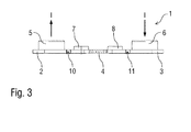
本発明に係る電流検出抵抗器1は、両方の板状接続部2、3と電気的かつ機械的に接続される二つの電流の接点5、6を有する。特に図3における側面図から判るように、電流接点6は測定される電流Iを流入させるよう用いられ、また電流接点5は測定される電流を流出させるよう機能する。
The
さらに、本発明に係る電流検出抵抗器1は二つの電圧接点7、8を有する。二つの電圧接点は、電気的かつ機械的に両方の板状接続部2、3と接続され、抵抗素子4において低下する電圧を測定するよう機能する。したがって、接続部2、3における電圧降下による電圧測定の悪影響を回避するために、両方の電圧接点7、8は、板状接続部2、3において抵抗素子4に非常に近接して配置される。
Furthermore, the
なお、本発明に係る電流検出抵抗器1は、抵抗素子4の領域の一方の側部に、切り欠き部分9を有する。製造時に切り欠き部分9を大きく又は小さくすることによって、電流検出抵抗器1を所望の抵抗値に較正、すなわち調整できる。このために切り欠き部分が用いられる。
The
ただ、本発明の機能では、測定の温度依存性を低減するためには、切り欠き部分10、11がそれぞれ両方の板状接続部2、3に一つ形成されることが重要である。ここで、両方の切り欠き部分10、11は、板状接続部2又は3の同じ側の縁部から横方向に内側に向かって延長され、さらにそれぞれの電圧接点7又は8の周りに円弧状に延設される。特に図4の詳細な図から判るように、両方の切り欠き部分10、11は、円弧角α≒70°で延設されている。
However, in the function of the present invention, in order to reduce the temperature dependency of the measurement, it is important that one
図4の詳細な図は、両方の切り欠き部分10、11がスリット状であり、その幅が切り欠き部分10、11の全長にわたって実質的に一定の幅bであることを示している。
The detailed view of FIG. 4 shows that both
図5A及び図5Bの比較から、両方の切り欠き部分10、11の機能は明らかである。図5Aは、従来の電流検出抵抗器1における電流線12及び等電位線13の経路を示しており、図5Bは本発明に係る電流検出抵抗器における電流線12及び等電位線13の経路を示している。ここで、電流線12は主要な電流方向として定義されている。切り欠き部分10、11は、電流の経路に影響を与えるよう、この主要な電流方向に対して横方向に延びている。
From the comparison of FIGS. 5A and 5B, the function of both
この比較から、図5Aに係る従来の電流検出抵抗器1においては、電圧接点7、8を通って延びる等電位線13が、抵抗素子4の外側縁部と正確に同じ電位ではないことを示している。このことは、電圧接点7、8の間で測定される電圧は、板状接続部2、3において低下する電圧を部分的に含んでいるのであって、一致していないことを意味する。したがって、測定される電圧も、接続部2、3の導電材料の比較的高い温依存性の影響を受ける。
This comparison shows that in the conventional
対照的に、図5Bに係る本発明の電流検出抵抗器1においては、電圧接点7、8を通って延びる等電位線が、抵抗素子4の外側縁部に達するよう、したがって同じ電位となるよう、切り欠き部分10、11が電流経路12及び等電位線13を湾曲させている。こうして、電圧測定の際には、抵抗素子4において低下する電圧のみが測定される。これには利点がある。板状接続部2、3の導電材料(例えば銅)の抵抗率に関する温度依存性が、抵抗素子4の抵抗材料(例えばマンガニン(登録商標))よりも、通常はかなり大きいからである。ここでは、等電位線13は、板状接続部2、3と抵抗素子4との間の溶接縁部に漸近的に接近していく。
In contrast, in the
温度Tの関数としての抵抗値Rの温度依存性を示す図6のグラフから判るように、切り欠き部分10、11を有する本発明に係る電流検出抵抗器1の設計により、電流測定の際の温度依存性を大きく低減できる。
As can be seen from the graph of FIG. 6 showing the temperature dependence of the resistance value R as a function of the temperature T, the design of the
本発明は、上述の好ましい例示的な実施形態に限定されない。むしろ、本発明の概念を用いた複数の変形及び変更が可能であり、したがって、それらは保護される範囲内である。さらに、本発明は引用している請求項の特徴を含んでいる従属請求項の主題の保護も主張するものである。 The present invention is not limited to the preferred exemplary embodiments described above. Rather, multiple variations and modifications using the inventive concept are possible and are therefore within the scope of protection. Furthermore, the invention claims protection of the subject matter of the dependent claims, including the features of the cited claims.
1…電流検出抵抗器
2…接続部
3…接続部
4…抵抗素子
5…電流接点
6…電流接点
7…電圧接点
8…電圧接点
9…切り欠き部分
10…切り欠き部分
11…切り欠き部分
12…電流線
13…等電位線
DESCRIPTION OF
Claims (12)
b)導電材料で形成され、測定される電流(I)を流出させるための板状第二接続部(2)と、
c)低オーム抵抗材料から形成され、両方の前記接続部間の電流経路に接続され、測定される電流(I)が流れる板状抵抗素子(4)と、
を備える、電流(I)を測定するための電流検出抵抗器(1)において、
d)切り欠き部分(10,11)を前記板状第一接続部(3)及び/又は板状第二接続部(2)に形成することで、測定の温度依存性を低減してなることを特徴とする電流検出抵抗器。 a) a plate-like first connection part (3) made of a conductive material for allowing the current (I) to be measured to flow in;
b) a plate-like second connection part (2) made of a conductive material and for allowing the current (I) to be measured to flow out;
c) a plate resistance element (4) formed of a low ohmic resistance material, connected to the current path between both said connections, and through which the current (I) to be measured flows;
In a current sensing resistor (1) for measuring current (I) comprising:
d) The temperature dependence of the measurement is reduced by forming the notched portions (10, 11) in the plate-like first connection portion (3) and / or the plate-like second connection portion (2). A current sensing resistor characterized by.
a)測定される電流(I)は、両方の前記接続部(2,3)間で主要な電流方向(12)に沿って流れ、
b)前記切り欠き部分(10,11)は、少なくともその長さの一部が前記主要な電流方向(12)に対して横方向に延設されてなることを特徴とする電流検出抵抗器。 The current sensing resistor (1) according to claim 1,
a) The measured current (I) flows along the main current direction (12) between both said connections (2,3),
b) The current detection resistor characterized in that the notched portions (10, 11) are at least partially extended in a direction transverse to the main current direction (12).
a)第一電圧接点(8)が、前記板状第一接続部(3)と電気的かつ機械的に接続されており、
b)第一切り欠き部分(11)が、前記板状第一接続部(3)に配置されており、
c)第二電圧接点(7)が、前記板状第二接続部(2)と電気的かつ機械的に接続されており、
d)第二切り欠き部分(10)が、前記板状第二接続部(2)に配置されてなることを特徴とする電流検出抵抗器。 In the current detection resistor (1) according to claim 1 or 2,
a) the first voltage contact (8) is electrically and mechanically connected to the plate-like first connection part (3);
b) The first notch portion (11) is arranged in the plate-like first connection portion (3),
c) the second voltage contact (7) is electrically and mechanically connected to the plate-like second connection (2);
d) A current detection resistor, wherein the second notch portion (10) is disposed in the plate-like second connection portion (2).
a)前記第一板状接続部(3)において、第一等電位線(13)が前記第一電圧接点(7)から前記抵抗素子(4)との接続点へ延びており、これにより前記第一電圧接点(7)は前記抵抗素子(4)との前記接続点と同じ電位となり、
b)前記第二板状接続部(2)において、第二等電位線(13)が前記第二電圧接点(8)から前記抵抗素子(4)との接続点へ延びており、これにより前記第二電圧接点(8)は前記抵抗素子(4)との前記接続点と同じ電位となることを特徴とする電流検出抵抗器。 The current sensing resistor (1) according to claim 3,
a) In the first plate-like connection portion (3), a first equipotential line (13) extends from the first voltage contact (7) to a connection point with the resistance element (4), thereby The first voltage contact (7) has the same potential as the connection point with the resistance element (4),
b) In the second plate-like connection portion (2), a second equipotential line (13) extends from the second voltage contact (8) to the connection point with the resistance element (4), thereby The current detection resistor, wherein the second voltage contact (8) has the same potential as the connection point with the resistance element (4).
a)前記第一接続部(3)における前記第一切り欠き部分(11)が、前記第一電圧接点(8)の前記抵抗素子(4)から離間している側に配置され、
b)前記板状第二接続部(2)における前記第二切り欠き部分(10)が、前記第二電圧接点(7)の前記抵抗素子(4)から離間している側に配置されてなることを特徴とする電流検出抵抗器。 The current detection resistor (1) according to claim 3 or 4,
a) the first notch portion (11) in the first connection portion (3) is disposed on the side of the first voltage contact (8) away from the resistance element (4);
b) The second notch portion (10) in the plate-like second connection portion (2) is disposed on the side of the second voltage contact (7) that is separated from the resistance element (4). A current detection resistor.
a)前記板状第一接続部(3)における前記第一切り欠き部分(11)が、前記第一電圧接点(8)の周囲において円弧状に又は角度を付けて延設されており、
b)前記板状第二接続部(2)における前記第二切り欠き部分(10)が、前記第二電圧接点(7)の周囲において円弧状に又は角度を付けて延設されてなることを特徴とする電流検出抵抗器。 In the current detection resistor (1) according to any one of claims 3 to 5,
a) The first notch portion (11) in the plate-like first connection portion (3) extends in an arc shape or at an angle around the first voltage contact (8),
b) The second notch portion (10) in the plate-like second connection portion (2) is formed to extend around the second voltage contact (7) in an arc shape or at an angle. Characteristic current sensing resistor.
a)前記切り欠き部分(10,11)が、円弧状に湾曲されており、かつ/又は
b)前記切り欠き部分(10,11)は、30°、40°、50°、60°又は70°を超える円弧角(α)で延設されてなることを特徴とする電流検出抵抗器。 In the current detection resistor (1) according to any one of claims 1 to 6,
a) the notch (10, 11) is curved in an arc and / or b) the notch (10, 11) is 30 °, 40 °, 50 °, 60 ° or 70 A current detection resistor characterized by being extended with an arc angle (α) exceeding °.
a)第一電圧接点(6)が、前記板状第一接続部(3)と電気的かつ機械的に接続されており、前記第一電流接点(6)は測定される電流(I)を流入させるよう機能し、
b)第二電圧接点(5)が、前記板状第二接続部(2)と電気的かつ機械的に接続されており、前記第二電流接点(5)は測定される電流(I)を流出させるよう機能してなることを特徴とする電流検出抵抗器。 In the current detection resistor (1) according to any one of claims 1 to 7,
a) The first voltage contact (6) is electrically and mechanically connected to the plate-like first connection part (3), and the first current contact (6) has a current (I) to be measured. Function to flow in,
b) The second voltage contact (5) is electrically and mechanically connected to the plate-like second connection part (2), and the second current contact (5) receives the current (I) to be measured. A current detection resistor characterized by functioning to flow.
a)前記切り欠き部分(10,11)が、その全長にわたって実質的に一定の幅(b)であり、かつ/又は
b)前記切り欠き部分(10,11)が、前記第一接続部及び/又は前記板状第二接続部(2)の縁部から内側へと延設され、かつ/又は
c)前記少なくとも一の切り欠き部分(10,11)は、前記抵抗素子(4)には達せず、これにより前記電圧接点(7,8)は、前記板状接続部(2,3)を介して前記抵抗素子(4)とその全幅にわたって接触できることを特徴とする電流検出抵抗器。 In the current detection resistor (1) according to any one of claims 1 to 9,
a) the notch (10, 11) has a substantially constant width (b) over its entire length; and / or b) the notch (10, 11) And / or extending inward from the edge of the plate-like second connection portion (2), and / or c) the at least one notch portion (10, 11) is provided on the resistance element (4). Therefore, the voltage contact (7, 8) can contact the resistance element (4) through the plate-like connecting portion (2, 3) over its entire width.
a)前記電流検出抵抗器(1)の抵抗値は、所定の温度係数を有する所定の抵抗値であり、
b)前記抵抗値の温度係数は、前記板状接続部(2,3)において切り欠き部分(10,11)を有しない他の同一の構造を有する前記電流検出抵抗器(1)よりも、少なくとも30%、40%、50%又は60%小さいことを特徴とする電流検出抵抗器。 In the current detection resistor (1) according to any one of claims 1 to 10,
a) The resistance value of the current detection resistor (1) is a predetermined resistance value having a predetermined temperature coefficient,
b) The temperature coefficient of the resistance value is higher than that of the current detection resistor (1) having the same structure other than the notched portion (10, 11) in the plate-like connection portion (2, 3). A current sensing resistor characterized by being at least 30%, 40%, 50% or 60% smaller.
a)前記導電材料は銅又は銅合金であり、かつ/又は
b)前記抵抗材料は銅合金特に銅マンガンニッケル合金、特にCu84Ni4Mn12であり、かつ/又は
c)前記抵抗素子(4)は、両方の前記接続部(2,3)と電気的かつ機械的に、特に溶接によって接続され、かつ/又は
d)両方の前記接続部(2,3)は、前記抵抗素子(4)の対向する側部に配置され、かつ/又は
e)前記板状接続部(2,3)及び/又は前記板状抵抗素子(4)は、平面状である又は湾曲されてなることを特徴とする電流検出抵抗器。 In the current detection resistor (1) according to any one of claims 1 to 11,
a) the conductive material is copper or a copper alloy, and / or b) the resistive material is a copper alloy, in particular a copper manganese nickel alloy, in particular Cu84Ni4Mn12, and / or c) the resistive element (4) is both Connected to the connecting part (2,3) electrically and mechanically, in particular by welding, and / or d) both connecting parts (2,3) are opposite sides of the resistance element (4) And / or e) the plate-like connecting portion (2, 3) and / or the plate-like resistive element (4) are planar or curved, .
Applications Claiming Priority (3)
| Application Number | Priority Date | Filing Date | Title |
|---|---|---|---|
| DE102010035485.6 | 2010-08-26 | ||
| DE102010035485A DE102010035485A1 (en) | 2010-08-26 | 2010-08-26 | Current sense resistor |
| PCT/EP2011/004245 WO2012019784A1 (en) | 2010-08-26 | 2011-08-24 | Current-sensing resistor |
Publications (2)
| Publication Number | Publication Date |
|---|---|
| JP2013536424A true JP2013536424A (en) | 2013-09-19 |
| JP2013536424A5 JP2013536424A5 (en) | 2014-12-11 |
Family
ID=44653244
Family Applications (1)
| Application Number | Title | Priority Date | Filing Date |
|---|---|---|---|
| JP2013525182A Pending JP2013536424A (en) | 2010-08-26 | 2011-08-24 | Current detection resistor |
Country Status (8)
| Country | Link |
|---|---|
| US (1) | US8884733B2 (en) |
| EP (1) | EP2446449B1 (en) |
| JP (1) | JP2013536424A (en) |
| KR (1) | KR101887405B1 (en) |
| CN (1) | CN103180916B (en) |
| DE (1) | DE102010035485A1 (en) |
| ES (1) | ES2684111T3 (en) |
| WO (1) | WO2012019784A1 (en) |
Cited By (11)
| Publication number | Priority date | Publication date | Assignee | Title |
|---|---|---|---|---|
| JP2016014596A (en) * | 2014-07-02 | 2016-01-28 | 株式会社ジェイテクト | Current detector |
| WO2016047010A1 (en) * | 2014-09-25 | 2016-03-31 | 三洋電機株式会社 | Electrical current detection device equipped with shunt resistor, and power supply device |
| JP2016180765A (en) * | 2016-07-12 | 2016-10-13 | Koa株式会社 | Shunt resistance type current detection device |
| KR101856670B1 (en) | 2017-12-12 | 2018-05-15 | (주)서준전기 | A bus bar for a distribution board capable of measuring a current by combining a shunt resistor and a method of manufacturing the same, and a bus bar module |
| WO2018229817A1 (en) * | 2017-06-12 | 2018-12-20 | 新電元工業株式会社 | Power module |
| JP2020145365A (en) * | 2019-03-08 | 2020-09-10 | サンコール株式会社 | Shunt resistor and manufacturing method therefor |
| WO2021100084A1 (en) * | 2019-11-18 | 2021-05-27 | サンコール株式会社 | Shunt resistor |
| WO2021220758A1 (en) * | 2020-04-28 | 2021-11-04 | Koa株式会社 | Shunt resistor |
| WO2022070623A1 (en) * | 2020-09-30 | 2022-04-07 | Koa株式会社 | Jumper element, shunt resistor device and method for adjusting charateristics of shunt resistor device for current detection |
| WO2023189742A1 (en) * | 2022-03-28 | 2023-10-05 | Koa株式会社 | Shunt resistor and current detection device |
| JP7567261B2 (ja) | 2020-07-31 | 2024-10-16 | 株式会社デンソー | 電流検出装置 |
Families Citing this family (29)
| Publication number | Priority date | Publication date | Assignee | Title |
|---|---|---|---|---|
| KR20170061185A (en) * | 2009-09-04 | 2017-06-02 | 비쉐이 데일 일렉트로닉스, 엘엘씨 | Resistor with temperature coefficient of resistance(tcr) compensation |
| DE102012013036B4 (en) * | 2012-06-29 | 2015-04-02 | Isabellenhütte Heusler Gmbh & Co. Kg | Resistance, in particular low-impedance current measuring resistor, and coating method for this purpose |
| US9523720B2 (en) * | 2013-03-15 | 2016-12-20 | Infineon Technologies Ag | Multiple current sensor device, a multiple current shunt device and a method for providing a sensor signal |
| JP6714974B2 (en) * | 2015-05-19 | 2020-07-01 | Koa株式会社 | Current detector |
| JP6795879B2 (en) * | 2015-06-15 | 2020-12-02 | Koa株式会社 | Resistor and its manufacturing method |
| CN107923952A (en) * | 2015-08-14 | 2018-04-17 | 大陆汽车有限公司 | Battery sensor units with high mechanical robustness |
| JP6695122B2 (en) * | 2015-10-15 | 2020-05-20 | サンコール株式会社 | Manufacturing method of shunt resistor |
| DE102015226665A1 (en) * | 2015-12-23 | 2017-06-29 | Robert Bosch Gmbh | Electrically conductive measuring layer for measuring a potential difference |
| KR102014468B1 (en) | 2016-03-07 | 2019-08-26 | 주식회사 엘지화학 | Apparatus for estimating charging and discharging current |
| JP6942438B2 (en) * | 2016-03-18 | 2021-09-29 | ローム株式会社 | Shunt resistor |
| DE102017203535A1 (en) | 2017-03-03 | 2018-09-06 | Continental Automotive Gmbh | Current sensor with optimized current density distribution, method for determining a load current |
| DE102017207713A1 (en) * | 2017-05-08 | 2018-11-08 | Robert Bosch Gmbh | Shunt resistor for detecting the state of an electrical energy storage unit |
| US10438730B2 (en) | 2017-10-31 | 2019-10-08 | Cyntec Co., Ltd. | Current sensing resistor and fabrication method thereof |
| CN108565082A (en) * | 2018-04-16 | 2018-09-21 | 张照亮 | Microhm current sense resistor |
| WO2020058487A1 (en) * | 2018-09-21 | 2020-03-26 | Continental Automotive Gmbh | Battery sensor for temperature-independent current measurement using a shunt |
| EP3664269A1 (en) * | 2018-12-07 | 2020-06-10 | Siemens Aktiengesellschaft | Measuring shunt |
| US11415601B2 (en) * | 2018-12-21 | 2022-08-16 | Cyntec Co., Ltd. | Resistor having low temperature coefficient of resistance |
| CN109975614B (en) * | 2019-02-18 | 2021-02-23 | 南京隆特集成电路科技有限公司 | Four-wire current sensing resistor and measuring method thereof |
| JP7491723B2 (en) * | 2020-04-20 | 2024-05-28 | Koa株式会社 | Shunt Resistor |
| DE102020111634B3 (en) * | 2020-04-29 | 2021-04-01 | Isabellenhütte Heusler Gmbh & Co. Kg | Current sense resistor |
| JP7523190B2 (en) * | 2020-08-20 | 2024-07-26 | ヴィシェイ デール エレクトロニクス エルエルシー | Resistor, current sensing resistor, battery shunt, shunt resistor, and methods of making same |
| EP3958002B1 (en) * | 2020-08-20 | 2024-03-13 | TE Connectivity Germany GmbH | Current sensor element, current sensor unit, and method of measuring a current |
| DE102020214083A1 (en) * | 2020-11-10 | 2022-05-12 | Continental Automotive Gmbh | Resistor assembly and battery sensor with resistor assembly |
| DE102020007556A1 (en) | 2020-12-10 | 2022-06-15 | Wieland-Werke Aktiengesellschaft | Resistor arrangement and method for its manufacture |
| DE102021103238A1 (en) | 2021-02-11 | 2022-08-11 | Isabellenhütte Heusler Gmbh & Co. Kg | current sensing resistor |
| US20240085459A1 (en) | 2021-02-11 | 2024-03-14 | Isabellenhütte Heusler Gmbh & Co. Kg | Current-sensing resistor |
| DE102021117637A1 (en) | 2021-07-08 | 2023-01-12 | Preh Gmbh | Measuring resistor for measuring electrical current, associated manufacturing process and current sensor containing the measuring resistor |
| DE102021122491B4 (en) * | 2021-08-31 | 2023-03-30 | Isabellenhütte Heusler Gmbh & Co. Kg | current sensing resistor |
| US12068092B2 (en) * | 2022-04-08 | 2024-08-20 | Cyntec Co., Ltd. | Structure of resistor device and system for measuring resistance of same |
Citations (9)
| Publication number | Priority date | Publication date | Assignee | Title |
|---|---|---|---|---|
| JPH0483175A (en) * | 1990-07-25 | 1992-03-17 | Mitsubishi Electric Corp | Current detector |
| JP2002519672A (en) * | 1998-06-30 | 2002-07-02 | デルタ・エレクトリカル・リミテッド | Current detector and current measuring device having such a detector |
| JP2002289412A (en) * | 2001-03-27 | 2002-10-04 | Tama Electric Co Ltd | Method for manufacturing resistor |
| JP2003232814A (en) * | 2002-02-06 | 2003-08-22 | Toshiba Corp | Current detection device and current detection device for inverter |
| JP2007221006A (en) * | 2006-02-17 | 2007-08-30 | Sanken Electric Co Ltd | Resistor including resistance element and method of resistance value inspection performed by resistor |
| US20090195348A1 (en) * | 2008-02-06 | 2009-08-06 | Vishay Dale Electronics, Inc. | Resistor, and method for making same |
| JP2009204531A (en) * | 2008-02-28 | 2009-09-10 | Sanyo Electric Co Ltd | Shunt resistor, and power supply device for vehicle equipped with the shunt resistor |
| JP2009266977A (en) * | 2008-04-24 | 2009-11-12 | Koa Corp | Metal plate resistor |
| JP2012528034A (en) * | 2009-05-28 | 2012-11-12 | イクスモシオン | Method and apparatus for attenuating narrowband noise in a vehicle passenger compartment |
Family Cites Families (7)
| Publication number | Priority date | Publication date | Assignee | Title |
|---|---|---|---|---|
| DE2939594A1 (en) * | 1979-09-29 | 1981-04-09 | Robert Bosch Gmbh, 7000 Stuttgart | High current electrical measurement resistance - with stamped and punched resistance path and current connections and welded tappings |
| DE4243349A1 (en) | 1992-12-21 | 1994-06-30 | Heusler Isabellenhuette | Manufacture of resistors from composite material |
| US5999085A (en) * | 1998-02-13 | 1999-12-07 | Vishay Dale Electronics, Inc. | Surface mounted four terminal resistor |
| US20040216303A1 (en) * | 2003-05-01 | 2004-11-04 | Berlin Carl W. | Thick film current sensing resistor and method |
| DE102009031408A1 (en) | 2009-07-01 | 2011-01-05 | Isabellenhütte Heusler Gmbh & Co. Kg | Electronic component and corresponding manufacturing method |
| KR20170061185A (en) * | 2009-09-04 | 2017-06-02 | 비쉐이 데일 일렉트로닉스, 엘엘씨 | Resistor with temperature coefficient of resistance(tcr) compensation |
| TWI428940B (en) * | 2011-11-15 | 2014-03-01 | Ta I Technology Co Ltd | Current sensing resistor and method for manufacturing the same |
-
2010
- 2010-08-26 DE DE102010035485A patent/DE102010035485A1/en not_active Withdrawn
-
2011
- 2011-08-24 US US13/819,020 patent/US8884733B2/en active Active
- 2011-08-24 JP JP2013525182A patent/JP2013536424A/en active Pending
- 2011-08-24 KR KR1020137007432A patent/KR101887405B1/en active IP Right Grant
- 2011-08-24 WO PCT/EP2011/004245 patent/WO2012019784A1/en active Application Filing
- 2011-08-24 EP EP11757765.0A patent/EP2446449B1/en active Active
- 2011-08-24 CN CN201180051101.6A patent/CN103180916B/en active Active
- 2011-08-24 ES ES11757765.0T patent/ES2684111T3/en active Active
Patent Citations (9)
| Publication number | Priority date | Publication date | Assignee | Title |
|---|---|---|---|---|
| JPH0483175A (en) * | 1990-07-25 | 1992-03-17 | Mitsubishi Electric Corp | Current detector |
| JP2002519672A (en) * | 1998-06-30 | 2002-07-02 | デルタ・エレクトリカル・リミテッド | Current detector and current measuring device having such a detector |
| JP2002289412A (en) * | 2001-03-27 | 2002-10-04 | Tama Electric Co Ltd | Method for manufacturing resistor |
| JP2003232814A (en) * | 2002-02-06 | 2003-08-22 | Toshiba Corp | Current detection device and current detection device for inverter |
| JP2007221006A (en) * | 2006-02-17 | 2007-08-30 | Sanken Electric Co Ltd | Resistor including resistance element and method of resistance value inspection performed by resistor |
| US20090195348A1 (en) * | 2008-02-06 | 2009-08-06 | Vishay Dale Electronics, Inc. | Resistor, and method for making same |
| JP2009204531A (en) * | 2008-02-28 | 2009-09-10 | Sanyo Electric Co Ltd | Shunt resistor, and power supply device for vehicle equipped with the shunt resistor |
| JP2009266977A (en) * | 2008-04-24 | 2009-11-12 | Koa Corp | Metal plate resistor |
| JP2012528034A (en) * | 2009-05-28 | 2012-11-12 | イクスモシオン | Method and apparatus for attenuating narrowband noise in a vehicle passenger compartment |
Cited By (17)
| Publication number | Priority date | Publication date | Assignee | Title |
|---|---|---|---|---|
| JP2016014596A (en) * | 2014-07-02 | 2016-01-28 | 株式会社ジェイテクト | Current detector |
| WO2016047010A1 (en) * | 2014-09-25 | 2016-03-31 | 三洋電機株式会社 | Electrical current detection device equipped with shunt resistor, and power supply device |
| JPWO2016047010A1 (en) * | 2014-09-25 | 2017-04-27 | 三洋電機株式会社 | Current detection device and power supply device with shunt resistor |
| JP2016180765A (en) * | 2016-07-12 | 2016-10-13 | Koa株式会社 | Shunt resistance type current detection device |
| WO2018229817A1 (en) * | 2017-06-12 | 2018-12-20 | 新電元工業株式会社 | Power module |
| KR101856670B1 (en) | 2017-12-12 | 2018-05-15 | (주)서준전기 | A bus bar for a distribution board capable of measuring a current by combining a shunt resistor and a method of manufacturing the same, and a bus bar module |
| JP7210335B2 (en) | 2019-03-08 | 2023-01-23 | サンコール株式会社 | Shunt resistor and its manufacturing method |
| WO2020184247A1 (en) * | 2019-03-08 | 2020-09-17 | サンコール株式会社 | Shunt resistor and manufacturing method therefor |
| JP2020145365A (en) * | 2019-03-08 | 2020-09-10 | サンコール株式会社 | Shunt resistor and manufacturing method therefor |
| WO2021100084A1 (en) * | 2019-11-18 | 2021-05-27 | サンコール株式会社 | Shunt resistor |
| JP6956263B1 (en) * | 2019-11-18 | 2021-11-02 | サンコール株式会社 | Shunt resistor |
| US12080452B2 (en) | 2019-11-18 | 2024-09-03 | Suncall Corporation | Shunt resistor |
| WO2021220758A1 (en) * | 2020-04-28 | 2021-11-04 | Koa株式会社 | Shunt resistor |
| JP7491727B2 (en) | 2020-04-28 | 2024-05-28 | Koa株式会社 | Shunt Resistor |
| JP7567261B2 (ja) | 2020-07-31 | 2024-10-16 | 株式会社デンソー | 電流検出装置 |
| WO2022070623A1 (en) * | 2020-09-30 | 2022-04-07 | Koa株式会社 | Jumper element, shunt resistor device and method for adjusting charateristics of shunt resistor device for current detection |
| WO2023189742A1 (en) * | 2022-03-28 | 2023-10-05 | Koa株式会社 | Shunt resistor and current detection device |
Also Published As
| Publication number | Publication date |
|---|---|
| EP2446449B1 (en) | 2018-06-13 |
| DE102010035485A1 (en) | 2012-03-01 |
| CN103180916B (en) | 2016-08-03 |
| US8884733B2 (en) | 2014-11-11 |
| EP2446449A1 (en) | 2012-05-02 |
| US20130181807A1 (en) | 2013-07-18 |
| KR101887405B1 (en) | 2018-09-11 |
| KR20130106830A (en) | 2013-09-30 |
| CN103180916A (en) | 2013-06-26 |
| ES2684111T3 (en) | 2018-10-01 |
| WO2012019784A1 (en) | 2012-02-16 |
Similar Documents
| Publication | Publication Date | Title |
|---|---|---|
| JP2013536424A (en) | Current detection resistor | |
| US9995771B2 (en) | Shunt resistor | |
| US7170295B2 (en) | Resistor arrangement, manufacturing method, and measurement circuit | |
| US20160041206A1 (en) | Measuring resistor and corresponding measuring method | |
| CN105874338A (en) | Shunt resistor and shunt resistor assembly | |
| JP2013536424A5 (en) | ||
| WO2012132470A1 (en) | Connecting terminal of shunt resistor, and battery state detecting apparatus | |
| JP7544609B2 (en) | Resistance device, measuring circuit with a resistance device and method for producing a strip-shaped material composite for a resistance device | |
| JP2023523986A (en) | current sense resistor | |
| CN116829961A (en) | Current detection resistor | |
| US10267824B2 (en) | Shunt resistor | |
| US20230170112A1 (en) | Shunt resistor, method for manufacturing shunt resistor, and current detection device | |
| US20150192622A1 (en) | Shunt Resistance Type Current Sensor | |
| JP6689510B2 (en) | Battery cell assembly | |
| CN208149135U (en) | seat occupancy sensor | |
| CN113077950B (en) | Resistor with a resistor element | |
| US20230081784A1 (en) | Resistor arrangement | |
| JP2020101542A (en) | Resistance assembly for battery sensor and battery sensor | |
| JP6082604B2 (en) | Shunt resistance type current sensor | |
| WO2024111254A1 (en) | Shunt resistor | |
| CN219418633U (en) | Resistor and power supply device for detecting current | |
| CN219066527U (en) | Resistor and power supply device for detecting current | |
| CN114624607A (en) | Resistor element and method for producing a resistor element | |
| CN114545230A (en) | Resistor assembly and battery sensor having the same | |
| JP3646219B2 (en) | Method for measuring ground resistance of ground electrode |
Legal Events
| Date | Code | Title | Description |
|---|---|---|---|
| RD01 | Notification of change of attorney |
Free format text: JAPANESE INTERMEDIATE CODE: A7426 Effective date: 20130801 |
|
| A621 | Written request for application examination |
Free format text: JAPANESE INTERMEDIATE CODE: A621 Effective date: 20130802 |
|
| A521 | Request for written amendment filed |
Free format text: JAPANESE INTERMEDIATE CODE: A821 Effective date: 20130802 |
|
| A977 | Report on retrieval |
Free format text: JAPANESE INTERMEDIATE CODE: A971007 Effective date: 20140213 |
|
| A131 | Notification of reasons for refusal |
Free format text: JAPANESE INTERMEDIATE CODE: A131 Effective date: 20140311 |
|
| A601 | Written request for extension of time |
Free format text: JAPANESE INTERMEDIATE CODE: A601 Effective date: 20140605 |
|
| A602 | Written permission of extension of time |
Free format text: JAPANESE INTERMEDIATE CODE: A602 Effective date: 20140612 |
|
| A601 | Written request for extension of time |
Free format text: JAPANESE INTERMEDIATE CODE: A601 Effective date: 20140710 |
|
| A602 | Written permission of extension of time |
Free format text: JAPANESE INTERMEDIATE CODE: A602 Effective date: 20140717 |
|
| A601 | Written request for extension of time |
Free format text: JAPANESE INTERMEDIATE CODE: A601 Effective date: 20140808 |
|
| A602 | Written permission of extension of time |
Free format text: JAPANESE INTERMEDIATE CODE: A602 Effective date: 20140815 |
|
| A521 | Request for written amendment filed |
Free format text: JAPANESE INTERMEDIATE CODE: A821 Effective date: 20140911 |
|
| A524 | Written submission of copy of amendment under article 19 pct |
Free format text: JAPANESE INTERMEDIATE CODE: A524 Effective date: 20140911 |
|
| A521 | Request for written amendment filed |
Free format text: JAPANESE INTERMEDIATE CODE: A523 Effective date: 20140925 |
|
| A02 | Decision of refusal |
Free format text: JAPANESE INTERMEDIATE CODE: A02 Effective date: 20141111 |