JP2013525845A - Metal detectable lens - Google Patents
Metal detectable lens Download PDFInfo
- Publication number
- JP2013525845A JP2013525845A JP2013506256A JP2013506256A JP2013525845A JP 2013525845 A JP2013525845 A JP 2013525845A JP 2013506256 A JP2013506256 A JP 2013506256A JP 2013506256 A JP2013506256 A JP 2013506256A JP 2013525845 A JP2013525845 A JP 2013525845A
- Authority
- JP
- Japan
- Prior art keywords
- layer
- metal
- lens
- detectable
- eyewear
- Prior art date
- Legal status (The legal status is an assumption and is not a legal conclusion. Google has not performed a legal analysis and makes no representation as to the accuracy of the status listed.)
- Pending
Links
Images


Classifications
-
- A—HUMAN NECESSITIES
- A61—MEDICAL OR VETERINARY SCIENCE; HYGIENE
- A61F—FILTERS IMPLANTABLE INTO BLOOD VESSELS; PROSTHESES; DEVICES PROVIDING PATENCY TO, OR PREVENTING COLLAPSING OF, TUBULAR STRUCTURES OF THE BODY, e.g. STENTS; ORTHOPAEDIC, NURSING OR CONTRACEPTIVE DEVICES; FOMENTATION; TREATMENT OR PROTECTION OF EYES OR EARS; BANDAGES, DRESSINGS OR ABSORBENT PADS; FIRST-AID KITS
- A61F9/00—Methods or devices for treatment of the eyes; Devices for putting-in contact lenses; Devices to correct squinting; Apparatus to guide the blind; Protective devices for the eyes, carried on the body or in the hand
- A61F9/02—Goggles
- A61F9/022—Use of special optical filters, e.g. multiple layers, filters for protection against laser light or light from nuclear explosions, screens with different filter properties on different parts of the screen; Rotating slit-discs
-
- A—HUMAN NECESSITIES
- A61—MEDICAL OR VETERINARY SCIENCE; HYGIENE
- A61F—FILTERS IMPLANTABLE INTO BLOOD VESSELS; PROSTHESES; DEVICES PROVIDING PATENCY TO, OR PREVENTING COLLAPSING OF, TUBULAR STRUCTURES OF THE BODY, e.g. STENTS; ORTHOPAEDIC, NURSING OR CONTRACEPTIVE DEVICES; FOMENTATION; TREATMENT OR PROTECTION OF EYES OR EARS; BANDAGES, DRESSINGS OR ABSORBENT PADS; FIRST-AID KITS
- A61F9/00—Methods or devices for treatment of the eyes; Devices for putting-in contact lenses; Devices to correct squinting; Apparatus to guide the blind; Protective devices for the eyes, carried on the body or in the hand
- A61F9/02—Goggles
- A61F9/029—Additional functions or features, e.g. protection for other parts of the face such as ears, nose or mouth; Screen wipers or cleaning devices
-
- G—PHYSICS
- G01—MEASURING; TESTING
- G01V—GEOPHYSICS; GRAVITATIONAL MEASUREMENTS; DETECTING MASSES OR OBJECTS; TAGS
- G01V15/00—Tags attached to, or associated with, an object, in order to enable detection of the object
-
- G02B1/105—
-
- G—PHYSICS
- G02—OPTICS
- G02B—OPTICAL ELEMENTS, SYSTEMS OR APPARATUS
- G02B1/00—Optical elements characterised by the material of which they are made; Optical coatings for optical elements
- G02B1/10—Optical coatings produced by application to, or surface treatment of, optical elements
- G02B1/14—Protective coatings, e.g. hard coatings
-
- G—PHYSICS
- G02—OPTICS
- G02C—SPECTACLES; SUNGLASSES OR GOGGLES INSOFAR AS THEY HAVE THE SAME FEATURES AS SPECTACLES; CONTACT LENSES
- G02C7/00—Optical parts
- G02C7/02—Lenses; Lens systems ; Methods of designing lenses
- G02C7/022—Ophthalmic lenses having special refractive features achieved by special materials or material structures
-
- G—PHYSICS
- G02—OPTICS
- G02C—SPECTACLES; SUNGLASSES OR GOGGLES INSOFAR AS THEY HAVE THE SAME FEATURES AS SPECTACLES; CONTACT LENSES
- G02C7/00—Optical parts
- G02C7/10—Filters, e.g. for facilitating adaptation of the eyes to the dark; Sunglasses
- G02C7/104—Filters, e.g. for facilitating adaptation of the eyes to the dark; Sunglasses having spectral characteristics for purposes other than sun-protection
Landscapes
- Health & Medical Sciences (AREA)
- Physics & Mathematics (AREA)
- Ophthalmology & Optometry (AREA)
- General Health & Medical Sciences (AREA)
- General Physics & Mathematics (AREA)
- Optics & Photonics (AREA)
- Life Sciences & Earth Sciences (AREA)
- Vascular Medicine (AREA)
- Veterinary Medicine (AREA)
- Heart & Thoracic Surgery (AREA)
- Engineering & Computer Science (AREA)
- Biomedical Technology (AREA)
- Animal Behavior & Ethology (AREA)
- Public Health (AREA)
- Otolaryngology (AREA)
- General Life Sciences & Earth Sciences (AREA)
- Geophysics (AREA)
- Spectroscopy & Molecular Physics (AREA)
- Eyeglasses (AREA)
- Laminated Bodies (AREA)
- Surface Treatment Of Optical Elements (AREA)
Abstract
第1の表面と第2の表面とを有し、かつ視覚的に透明な材料を含む第1の層と、第1の層の第1の表面上に配置される第2の層とを含み、第2の層が導電材料の層である、金属検出可能なレンズ。少なくとも1枚のかかる金属検出可能なレンズを備えるアイウェア、及び金属検出可能なアイウェアの少なくとも一部を検出する方法もまた開示される。
A first layer having a first surface and a second surface and comprising a visually transparent material; and a second layer disposed on the first surface of the first layer. A metal detectable lens, wherein the second layer is a layer of conductive material. Also disclosed are eyewear comprising at least one such metal detectable lens and a method of detecting at least a portion of the metal detectable eyewear.
Description
本開示は、金属検知器によって検出可能なレンズに関する。 The present disclosure relates to a lens detectable by a metal detector.
食品業界などの様々な業界で利用される自動機械は、金属の切粉又は細片を生じさせる可能性がある。そのような混入を防ぐために、金属検知器を使用してそうしたプロセスを監視する。典型的に使用される金属検知器は、2つの磁場を発生させ、その中央に変換器を有する。コンバーターは、2つの磁場を比較して、磁界の偏差を検出する。磁界の偏差は、検出領域内に金属が存在することを示す。 Automated machines used in various industries, such as the food industry, can produce metal chips or strips. To prevent such contamination, metal detectors are used to monitor such processes. Typically used metal detectors generate two magnetic fields and have a transducer in the middle. The converter compares the two magnetic fields and detects the magnetic field deviation. The magnetic field deviation indicates the presence of metal in the detection area.
目に入る様々な混入物質から労働者を保護するために、食品業界の労働者は通常、保護アイウェアを装着する。一般に使用される保護アイウェアが食品工業機械の中に落ちると、めがねは粉砕される可能性があり、肉眼ではほぼ検出不可能な場合があり得る。少なくともその理由で、保護アイウェア又は保護アイウェアの一部がそのような環境下で検出可能であれば有利であろう。 In order to protect workers from various contaminants entering the eye, food industry workers typically wear protective eyewear. When commonly used protective eyewear falls into the food industry machine, the glasses can be crushed and can be almost undetectable with the naked eye. For at least that reason, it would be advantageous if protective eyewear or a portion of protective eyewear could be detected in such an environment.
金属検出可能な(metal detectable)安全レンズが本明細書に開示され、該金属検出可能な安全レンズは、第1の表面と第2の表面とを有し、かつ視覚的に透明な材料を含む第1の層、及び導電材料の層であり第1の層の第1の表面上に配置される第2の層を含む。 A metal detectable safety lens is disclosed herein, the metal detectable safety lens having a first surface and a second surface and comprising a visually transparent material. A first layer and a second layer disposed on the first surface of the first layer, the layer being of a conductive material.
レンズキャリアと、少なくとも1枚の金属検出可能なレンズとを備える金属検出可能なアイウェアもまた開示され、少なくとも1枚の金属検出可能なレンズは、第1の表面と第2の表面とを有し、かつ視覚的に透明な材料を含む第1の層、及び導電材料の層であり第1の層の第1の表面上に配置される第2の層を含み、レンズキャリアは、少なくとも1枚の金属検出可能なレンズを保持するように構成され、金属検出可能なアイウェアは、少なくとも1枚の金属検出可能なレンズを通して見るユーザーにより装着され得る。 A metal detectable eyewear comprising a lens carrier and at least one metal detectable lens is also disclosed, the at least one metal detectable lens having a first surface and a second surface. And a first layer comprising a visually transparent material and a second layer that is a layer of conductive material and is disposed on the first surface of the first layer, wherein the lens carrier comprises at least one The metal-detectable eyewear is configured to hold a sheet of metal-detectable lens and can be worn by a user viewing through at least one metal-detectable lens.
金属検出可能なアイウェアの少なくとも一部の検出方法も開示され、該方法は、金属検出可能なアイウェアの少なくとも一部を提供する工程であって、金属検出可能なアイウェアの一部が、第1の表面と第2の表面とを有し、かつ視覚的に透明な材料を含む第1の層、及び導電材料の層であり前記第1の層の前記第1の表面上に配置される第2の層を含む、金属検出可能なアイウェアの少なくとも一部を提供する工程と、金属検出可能なアイウェアの一部を金属検知器に通す工程と、金属検知器の使用によってレンズ中の導電材料を検出することによって、金属検出可能なアイウェアの一部を検出する工程と、を含む。 A method of detecting at least a portion of metal detectable eyewear is also disclosed, the method comprising providing at least a portion of metal detectable eyewear, wherein the portion of the metal detectable eyewear comprises: A first layer having a first surface and a second surface and comprising a visually transparent material; and a layer of conductive material disposed on the first surface of the first layer. Providing at least a portion of the metal detectable eyewear comprising a second layer, passing the portion of the metal detectable eyewear through the metal detector, and using the metal detector in the lens. Detecting a portion of the metal-detectable eyewear by detecting a conductive material.
以下の本開示の異なる実施形態の詳細な説明を添付図面と併せて考慮することで、本開示のより完全な理解が可能である。
図面は、必ずしも縮尺にしたがうものではない。図面で用いられる同様の番号は同様の構成要素を示すものとする。ただし、与えられた図の構成要素を示す数字の使用は、同じ数字を付された別の図の構成要素を限定することを意図するものではないことが理解されよう。 The drawings are not necessarily to scale. Like numbers used in the drawings shall refer to like components. It will be understood, however, that the use of numerals indicating the components of a given figure is not intended to limit the elements of another figure that are marked with the same numeral.
次の記述において、本明細書の一部を構成する添付の図面を参照し、いくつかの特定の実施形態を例として示す。本開示の範囲及び趣旨から逸脱することなく、他の実施形態が想到され、実施され得る点は理解されるはずである。したがって、以下の詳細な説明は、限定的な意味で解釈されるべきではない。 In the following description, certain specific embodiments are shown by way of example with reference to the accompanying drawings, which form a part hereof. It should be understood that other embodiments can be devised and practiced without departing from the scope and spirit of the present disclosure. The following detailed description is, therefore, not to be construed in a limiting sense.
本明細書で使用するすべての科学用語及び専門用語は、特に指示がない限り、当該技術分野において一般的に使用される意味を有する。本明細書にて提供される定義は、本明細書でしばしば使用される幾つかの用語の理解を促進しようとするものであり、本開示の範囲を限定するものではない。 All scientific and technical terms used herein have meanings commonly used in the art unless otherwise specified. The definitions provided herein are intended to facilitate the understanding of some terms often used herein and are not intended to limit the scope of the present disclosure.
他に指示がない限り、本明細書及び特許請求の範囲で使用される特徴の大きさ、量、物理的特性を表わす数字はすべて、どの場合においても用語「約」によって修飾されるものとして理解されるべきである。それ故に、そうでないことが示されない限り、前述の明細書及び添付の特許請求の範囲で示される数値パラメータは、当業者が本明細書で開示される教示内容を用いて、目標対象とする所望の特性に応じて、変化し得る近似値である。 Unless otherwise indicated, all numbers representing the size, quantity, and physical properties of features used in the specification and claims are understood to be modified by the term “about” in any case. It should be. Therefore, unless indicated to the contrary, the numerical parameters set forth in the foregoing specification and the appended claims are not intended to be targeted by those skilled in the art using the teachings disclosed herein. It is an approximate value that can vary depending on the characteristics of
終点による数の範囲の記述は、その範囲内(例えば、1〜5は、1、1.5、2、2.75、3、3.80、4、及び5を含む)及びその範囲内の任意の範囲に包含される全ての数を含む。 Description of a range of numbers by endpoint is within that range (eg 1 to 5 includes 1, 1.5, 2, 2.75, 3, 3.80, 4, and 5) and within that range Includes all numbers included in any range.
本明細書及び添付の特許請求の範囲において使用されるとき、単数形「a」、「an」及び「the」は、その内容が特に明確に指示しない限り、複数の指示対象を有する実施形態を包含する。内容によってそうでないことが明らかに示されないかぎり、本明細書及び添付の「特許請求の範囲」において使用するところの「又は」なる語は、「及び/又は」を含めた意味で広く用いられる。 As used in this specification and the appended claims, the singular forms “a”, “an”, and “the” refer to embodiments having a plurality of referents unless the content clearly dictates otherwise. Include. Unless the context clearly indicates otherwise, the term “or” as used herein and in the appended claims is used broadly to mean “and / or”.
金属検出可能なアイウェアレンズなどの、保護アイウェアで使用することができる金属検出可能なレンズが、本明細書にて開示される。本開示の例示の実施形態は、有利には、食品加工領域内の金属片を検出するために既に配置済みのものと同一設備によって検出可能であり得る。 Disclosed herein are metal detectable lenses that can be used in protective eyewear, such as metal detectable eyewear lenses. Exemplary embodiments of the present disclosure may advantageously be detectable by the same equipment already deployed to detect metal pieces in the food processing area.
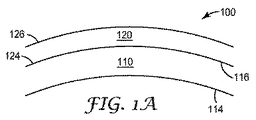
開示されるレンズは、少なくとも第1の層と第2の層とを含む。図1は、開示されるレンズの一部の略図を示している。図1のレンズ100は、第1の表面114と第2の表面116とを有する第1の層110を含む。レンズはまた、第1の表面124と第2の表面126とを有する第2の層120を含む。第2の層120は、一般に、第1の層110の第2の表面116に隣接して配置される。例示の実施形態において、第2の層120は、第1の層110に直接隣接して又は第1の層110の上に(いくつかの実施形態では、第1の層110の上に直接)配置され得る。いくつかの実施形態において、第2の層120の第1の表面124は、第1の層110の第2の表面116に隣接して、第2の表面116上に、第2の表面116上に直接隣接して、又は第2の表面116上に直接配置される。第1及び第2という表記法は、本明細書においては一般に参照目的で使用され、制限を加えるものとして受け取るべきではない。
The disclosed lens includes at least a first layer and a second layer. FIG. 1 shows a schematic diagram of a portion of the disclosed lens. The
第1の層110は、一般に、レンズ製造用原料として一般に使用される材料から作製され得る。典型的な実施形態において、第1の層を製造する材料は、視覚的に透明な材料であることができ、又は視覚的に透明な材料を含むことができる。好ましくは、第1の層は、高度な透明性(例えば、典型的な保護アイウェアレンズの透明度)を有する必要があり、それにより、第1の層を通して見るユーザーはクリアな視界を有することになる。いくつかの実施形態において、第1の層は、透明なポリマー材料で作製され得る。射出成形、キャスティング、又は押し出しされることができる透明なポリマー材料が好ましい。代表的なポリマー材料としては、例えばポリカーボネート、例えば、TRIVEX(登録商標)レンズ材料(PPG Industries(Pittsburgh,PA))、及びSabic Innovative Plastics(Pittsfield,MA)から入手可能な樹脂、又はこれらの組み合わせが挙げられる。他の例示的な実施形態において、第1の層は、ガラス、アセテート、セルロースプロピオネート、又はCR−39(アリルジグリコールカーボネート)で作製され得る。他の実施形態では、第1の層はポリカーボネートで作製され得る。
The
一般に、第1の層110は、一般にレンズ(例えば、保護アイウェア用レンズ)用に用いられる厚さを有することができる。いくつかの実施形態では、第1の層の厚さは、レンズ領域全体にわたって一定である必要はない。例えば、いくつかの実施形態では、第1の層は、レンズの内部が薄くなり得る。便宜上、ここで提供される厚さは、レンズのあらゆる一点における第1の層の最小厚さを指すものとする。複数の実施形態において、第1の層は、約0.5mm〜約5mmの厚さを有することができる。複数の実施形態において、第1の層は、約1mm〜約5mmの厚さを有することができる。
In general, the
第1の層に隣接して配置され得る第2の層120は、導電材料で作製されるのが好ましい。第2の層は、典型的には、導電材料を含有するポリマー分散体ではない。好ましくは、第2の層は、導電材料の層であり、いくつかの実施形態では、第2の層は、導電材料のみで作製される層である。他の実施形態において、第2の層は導電材料から本質的になる。
The
典型的な実施形態において、第2の層120は、第2の層の厚さで視覚的に透明な導電材料で作製され得る。いくつかの実施形態では、第2の層の厚さ(又は導電材料の質量/レンズの面積)は、第2の層の材料の導電性が増加するにつれて減少することができる。より少量のより導電性の材料(ある程度まで)は、依然として金属検知器によって検出されることができるので、このことは概ね当てはまる。より薄い(又は導電材料の質量が小さい/レンズの面積が小さい)第2の層は、視覚的により透明である可能性が高くあり得るので、有利であり得る。
In an exemplary embodiment, the
いくつかの実施形態では、第2の層は、銀(Ag)、銅(Cu)、金(Au)、チタン(Ti)、クロム(Cr)、又はこれらの組み合わせなどの導電材料で作製されることができる。 In some embodiments, the second layer is made of a conductive material such as silver (Ag), copper (Cu), gold (Au), titanium (Ti), chromium (Cr), or combinations thereof. be able to.
いくつかの例示的な実施形態において、第2の層の厚さは、少なくとも約1200オングストローム(Å)であり得る。第2の層が銀で作製される実施形態では、第2の層は、少なくとも約1200Åの厚さを有することができる。他の実施形態において、第2の層の厚さは、少なくとも約1400Åであり得る。第2の層が銀で作製される他の実施形態では、第2の層は、少なくとも約1400Åの厚さを有することができる。更に他の実施形態において、第2の層の厚さは、少なくとも約1500Åであることができる。例えば、いくつかの実施形態において、銀で作製される第2の層は、少なくとも約1500Åの厚さを有することができる。 In some exemplary embodiments, the thickness of the second layer can be at least about 1200 angstroms (Å). In embodiments where the second layer is made of silver, the second layer can have a thickness of at least about 1200 mm. In other embodiments, the thickness of the second layer can be at least about 1400 mm. In other embodiments where the second layer is made of silver, the second layer can have a thickness of at least about 1400 inches. In yet other embodiments, the thickness of the second layer can be at least about 1500 mm. For example, in some embodiments, the second layer made of silver can have a thickness of at least about 1500 mm.
本開示の典型的な実施形態では、第2の層120は、層の厚さ当たりの導電性によって表わされ得る。いくつかの実施形態において、第2の層は、少なくとも約18ジーメンス/mの導電性を有することができる。他の実施形態において、第2の層は、少なくとも約21ジーメンス/mの導電性を有することができる。更に他の実施形態において、第2の層は、少なくとも約22.5ジーメンス/mの導電性を有することができる。
In an exemplary embodiment of the present disclosure, the
図1Bは、開示されるレンズの別の例示的な実施形態を概略的に示している。例示的なレンズ150は、上述のように第1の層110と第2の層120とを含むことができ、また、任意に1つ又は2つ以上の他の層を含むことができる。この例示的な実施形態は、1つ又は2つ以上の中間層130を含むことができる。中間層130は、一般に、第1の層110と第2の層120との間に配置され得る。中間層130は、第2の層120を第1の層110に固着するのを支援するように機能し得る。
FIG. 1B schematically illustrates another exemplary embodiment of the disclosed lens. The
1つ又は2つ以上の中間層130は、第1の層材料と第2の層材料との付着を強化するように機能する数多くの材料で製造され得る。代表的な材料としては、例えば、二酸化チタン(TiO2)、SiO2、クロム(Cr)、又はこれらの組み合わせが挙げられる。いくつかの実施形態において、中間層の材料は、第1の層材料と第2の層材料との付着を強化するように機能することができ、更には、適用された厚さで視覚的に透明であり得る。
One or more
中間層が厚くなり過ぎると、そのことがレンズの光透過性に有害な悪影響を及ぼす可能性があり、中間層の有効性を高めることにならない。中間層が薄くなり過ぎると、そのことが中間層の有効性を低下させる可能性ある。中間層の好ましい厚さは、約200Å〜約6000Åの範囲であり得る。いくつかの実施形態では、中間層は、約400Å〜約1000Åの厚さを有することができる。 If the intermediate layer becomes too thick, it can have a detrimental adverse effect on the light transmission of the lens and does not increase the effectiveness of the intermediate layer. If the intermediate layer becomes too thin, it can reduce the effectiveness of the intermediate layer. A preferred thickness for the intermediate layer can range from about 200 to about 6000 inches. In some embodiments, the intermediate layer can have a thickness of about 400 inches to about 1000 inches.
図1Bに示されるレンズ150の例示的な実施形態はまた、1つ又は2つ以上の保護層140を任意に含むことができる。保護層140は、一般に、第2の層120に隣接して配置され得る。複数の実施形態において、保護層140は、第2の層120に直接隣接して、第2の層120の上に、又は第2の層120の上に直接配置され得る。複数の実施形態において、保護層140は、第2の層120の第2の表面126上に配置され得る。複数の実施形態において、保護層140は、第2の層120の第2の表面126に直接隣接して、第2の表面126の上に、又は第2の表面126の上に直接配置され得る。
The exemplary embodiment of the
1つ又は2つ以上の保護層140は、第2の層120を保護するように機能し得る任意の材料で作製され得る。第2の層に使用することができる一部の材料は、大気に暴露されることによって酸化されてもよい。1つ又は2つ以上の保護層140の追加は、少なくとも部分的に、第2の層120の酸化状態になる可能性のある材料の量を抑える又は減少させるのに役立ち得る。第2の層120として銀を使用する実施形態では、銀は大気への暴露によって酸化され得るので、かかる実施形態は、任意の保護層140の使用から恩恵を受けることができる。保護層140はまた、第2の層120を物理的ダメージ(酸化が一例である化学的損傷ではない)から保護するように機能することができる。
One or more
保護層140は、第2の層の材料を保護するように機能することができる数多くの材料を含むことができ、又はそれらで作製され得る。代表的な材料としては、例えば、二酸化チタン(TiO2)、SiO2、クロム(Cr)、又はこれらの組み合わせが挙げられる。複数の実施形態において、保護層の材料は、第2の層を保護するように機能することができ、更には、適用された厚さで視覚的に透明であり得る。
The
保護層が厚くなり過ぎると、そのことがレンズの光透過性に有害な悪影響を及ぼす可能性があり、保護層の有効性を高めることにならない。保護層が薄くなり過ぎると、そのことが保護層の有効性を低下させる可能性がある。保護層の好ましい厚さは、約200Å〜約6000Åの範囲であり得る。いくつかの実施形態では、中間層は、約400Å〜約1000Åの厚さを有することができる。 If the protective layer becomes too thick, it can have a detrimental adverse effect on the light transmission of the lens and does not increase the effectiveness of the protective layer. If the protective layer becomes too thin, it can reduce the effectiveness of the protective layer. The preferred thickness of the protective layer can range from about 200 to about 6000 inches. In some embodiments, the intermediate layer can have a thickness of about 400 inches to about 1000 inches.
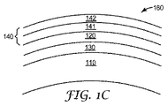
いくつかの例示的な実施形態において、保護層140は、2つ以上の層及び/又は2種類以上の材料を含むことができる。そのような実施形態は図1Cに示されている。例えば、開示されるかかるレンズ160は、化学的損傷防止層141と物理的損傷保護層142とを含む保護層140を含む。化学的損傷防止層141は、化学暴露及び、例えば酸化による劣化から第2の層を保護するように機能し得る材料の層を含むことができる。物理的損傷防止層142は、第2の層及び/又は化学的損傷防止層を、物理的損傷から保護するように機能し得る材料の層を含むことができる。
In some exemplary embodiments, the
そのような実施形態では、化学的損傷防止層141は第2の層120と接触状態にあることができ、物理的損傷防止層142は化学的損傷防止層141と接触状態にあることができる。そのような実施形態では、化学的損傷防止層は、一体型保護層140に関して上述したような材料で作製されることができ、物理的損傷防止層は、物理的損傷からの保護を提供するように選択される材料で作製され得る。代表的な材料としては、ハードコーティング及び引っかき抵抗に使用されるもののようなポリマー材料が挙げられる。特定の代表的な材料としては、例えば、ケイ素系材料が挙げられる。
In such an embodiment, the chemical damage prevention layer 141 can be in contact with the
一般に、開示されるレンズは、既知の技術を用いて製造され得る。例えば、金属材料(例えば、第2の層、中間層、一体型保護層、又は多層保護層の酸化防止層の材料)の蒸着は、化学蒸着、物理蒸着、電子ビーム蒸着、熱蒸着を用いて達成され得る。非金属材料(例えば、多層保護層のトップコート層の材料)の蒸着は、例えば様々なコーティング法(例えばディップコーティング法、スプレーコーティング法、又はスピンコーティング法など)によって達成され得る。 In general, the disclosed lenses can be manufactured using known techniques. For example, the vapor deposition of a metal material (for example, the material of the second layer, intermediate layer, integral protective layer, or antioxidant layer of the multilayer protective layer) uses chemical vapor deposition, physical vapor deposition, electron beam vapor deposition, thermal vapor deposition Can be achieved. Deposition of non-metallic materials (eg, the material of the topcoat layer of the multilayer protective layer) can be accomplished, for example, by various coating methods (eg, dip coating, spray coating, or spin coating).
このように、本開示によると、例示的なレンズの少なくとも一部は、金属検出可能であり得る。例えば、そのようなレンズが断裂した場合、そのレンズの一部も同様に金属検出可能であり得る。いくつかの実施形態において、開示されるレンズは、1.5mmの鋼球の同等物を検出するように設定された金属検知器によって検出され得る。他の実施形態では、開示されるレンズの一部は、1.5mmの鋼球の同等物を検出するように設定された金属検知器によって検出され得る。更に他の実施形態では、開示されるレンズの約0.08gの小さい一部は、1.5mmの鋼球の同等物を検出するように設定された金属検知器によって検出され得る。 Thus, according to the present disclosure, at least some of the exemplary lenses may be metal detectable. For example, if such a lens is torn, a portion of that lens may be metal detectable as well. In some embodiments, the disclosed lens can be detected by a metal detector set to detect the equivalent of a 1.5 mm steel ball. In other embodiments, a portion of the disclosed lens may be detected by a metal detector set to detect the equivalent of a 1.5 mm steel ball. In yet another embodiment, a small portion of about 0.08 g of the disclosed lens can be detected by a metal detector set to detect the equivalent of a 1.5 mm steel ball.
例えば、開示されるレンズは、一般に、保護アイウェアなどのアイウェアの1枚又は2枚以上のレンズとして使用され得る。アイウェアのレンズの場合、レンズは一般に、視覚的に透明であり得る。視覚的に透明なレンズは、約380nm〜約2000nmの波長で少なくとも約8%の透過率を有するものとして特徴付けられ得る。複数の実施形態において、本明細書に開示されるレンズは、約380nm〜約750nmの波長で少なくとも約40%の透過率を有するものとして特徴付けられ得る。 For example, the disclosed lenses can generally be used as one or more lenses for eyewear, such as protective eyewear. In the case of eyewear lenses, the lenses may generally be visually transparent. A visually transparent lens can be characterized as having a transmission of at least about 8% at a wavelength of about 380 nm to about 2000 nm. In embodiments, the lenses disclosed herein can be characterized as having a transmission of at least about 40% at a wavelength of about 380 nm to about 750 nm.
開示されるレンズが保護アイウェアの1枚又は2枚以上のレンズとして幅広く使用されるようにするためには、レンズは種々の構造試験に耐えることができなければならない。開示されるレンズは、単独又は安全レンズキャリア(以下に記載)と組み合わされた場合のいずれかで、保護メガネのための種々の標準試験に合格すると予想される。例えば、開示されるレンズは、例えばANSI Z87.1などの安全ガラス工業基準(industrial safety glass standards)に合格することができる。ANSI Z87.1は、保護メガネが、45.7メートル/秒(約150フィート/秒)の速度で移動する直径6.35mm(1/4インチ)の鋼球による衝撃に耐えることができることを要求する。ANSI Z87.1は、安全ゴーグルが、76.2メートル/秒(約250フィート/秒)の速度で移動する直径6.35mm(1/4インチ)の鋼球による衝撃に耐えることができることを要求する。ANSI Z87.1は、安全シールドが、91.4メートル/秒(約300フィート/秒)の速度で移動する直径6.35mm(1/4インチ)の鋼球による衝撃に耐えることができることを要求する。開示されるレンズは、安全レンズキャリアと組み合わされて、保護アイウェア工業基準(industrial safety eyewear standards)に合格すると予想される。 In order for the disclosed lens to be widely used as one or more lenses in protective eyewear, the lens must be able to withstand various structural tests. The disclosed lenses are expected to pass various standard tests for protective glasses, either alone or when combined with a safety lens carrier (described below). For example, the disclosed lenses can pass industrial safety glass standards such as ANSI Z87.1. ANSI Z87.1 requires that protective glasses can withstand the impact of a steel ball with a diameter of 6.35 mm (1/4 inch) moving at a speed of 45.7 meters / second (about 150 feet / second). To do. ANSI Z87.1 requires safety goggles to withstand the impact of a steel ball with a diameter of 6.35 mm (1/4 inch) moving at a speed of 76.2 meters / second (about 250 feet / second). To do. ANSI Z87.1 requires safety shields to withstand the impact of steel balls with a diameter of 6.35 mm (1/4 inch) moving at a speed of 91.4 meters / second (about 300 feet / second). To do. The disclosed lens is expected to pass the industrial safety eyewear standards in combination with a safety lens carrier.
本開示によるレンズキャリアは、少なくとも1枚のレンズを保持し、かつユーザーがレンズを通して見る様式でユーザーがレンズを着用できるように構成される構造体又は構造体の一部である。レンズキャリアは、組み合わされて少なくとも1枚のレンズを保持する、1つ又は2つ以上の部品を含むことができる。レンズキャリアは、一般に、通常使用される材料又は任意のその他の好適な材料で作製され得る。例えば、レンズキャリア全体又はレンズキャリアの一部を製造するために、ポリマー材料を使用することができる。少なくとも1枚のレンズは、レンズキャリアによって解放可能に保持され得、又は、レンズキャリアによって恒久的に保持され得る。例えば、レンズキャリアは、1枚のレンズ又は2枚のレンズと組み合わされ得る。少なくとも1つの開示される金属検出可能なレンズとレンズキャリアとの組み合わせにより、例えば、メガネ、ゴーグル、サンバイザー、又はシールドなどの金属検出可能なアイウェアをもたらすことができる。 A lens carrier according to the present disclosure is a structure or part of a structure that is configured to hold at least one lens and allow the user to wear the lens in a manner that the user sees through the lens. The lens carrier can include one or more parts that are combined to hold at least one lens. The lens carrier can generally be made of commonly used materials or any other suitable material. For example, a polymer material can be used to manufacture the entire lens carrier or a portion of the lens carrier. The at least one lens can be releasably held by the lens carrier or can be permanently held by the lens carrier. For example, the lens carrier can be combined with one lens or two lenses. The combination of at least one disclosed metal detectable lens and lens carrier can result in metal detectable eyewear such as glasses, goggles, sun visors, or shields, for example.
いくつかの例示的な実施形態では、レンズキャリア又はそれらの構成要素の少なくともいくつかを製造するために、熱可塑性ポリマーを使用することができる。使用することができるポリマーとしては、比較的硬い剛性材料が挙げられる。代表的なポリマー材料としては、例えば、ポリアミド、ポリオレフィン、ポリカーボネート、ビニールポリマー、ポリエーテル、及びこれらのコポリマー(例えば熱可塑性エラストマー)が挙げられる。ポリアミドの例としては、例えば、ナイロン−6、ナイロン−6,6及びナイロン−6/6,6コポリマー、ナイロン−11、ナイロン−12、並びにこのようなポリアミドのブレンドが挙げられる。ポリオレフィンの例としては、例えば、ポリエチレン、ポリスチレン、及びポリプロピレン、並びにアクリロニトリルブタジエンスチレンコポリマーなどのかかるポリマーを含むコポリマーが挙げられる。ポリカーボネート類の例としては、例えば、ポリカーボネート、及びポリビスフェノールAが挙げられる。ビニールポリマーの例としては、ポリ塩化ビニル(PVC)が挙げられる。ポリエーテルの例としては、ポリオキシメチレン(POM)が挙げられる。複数の実施形態において、レンズキャリアは、ポリアミド、例えばナイロン(例えばナイロン6−6)で製造され得る。 In some exemplary embodiments, thermoplastic polymers can be used to manufacture at least some of the lens carriers or their components. Polymers that can be used include relatively hard rigid materials. Exemplary polymeric materials include, for example, polyamides, polyolefins, polycarbonates, vinyl polymers, polyethers, and copolymers thereof (eg, thermoplastic elastomers). Examples of polyamides include, for example, nylon-6, nylon-6,6 and nylon-6 / 6,6 copolymers, nylon-11, nylon-12, and blends of such polyamides. Examples of polyolefins include, for example, copolymers containing such polymers such as polyethylene, polystyrene, and polypropylene, and acrylonitrile butadiene styrene copolymers. Examples of polycarbonates include polycarbonate and polybisphenol A. An example of a vinyl polymer is polyvinyl chloride (PVC). An example of a polyether is polyoxymethylene (POM). In embodiments, the lens carrier can be made of polyamide, such as nylon (eg, nylon 6-6).
ポリマー材料はまた、例えば、架橋剤、抗酸化剤、加工助剤、紫外線安定剤、界面活性剤、顔料、染料、結合剤、可塑剤、懸濁化剤、難燃剤、及び促進剤などの任意の添加剤を含有してもよい。これら材料の量は、一般に、所望の特性をもたらすように選択され得る。複数の実施形態において、ポリマー材料は、例えば、少なくとも紫外線安定剤と染料とを含むことができる。 The polymeric material can also be any such as, for example, crosslinkers, antioxidants, processing aids, UV stabilizers, surfactants, pigments, dyes, binders, plasticizers, suspending agents, flame retardants, and accelerators. The additive may be contained. The amounts of these materials can generally be selected to provide the desired properties. In embodiments, the polymeric material can include, for example, at least a UV stabilizer and a dye.
ポリマー材料は、あらゆるタイプのレンズキャリアに形成され得る。本明細書に開示されるレンズキャリアは、(2つ以上の構成要素の場合と合わせて)1枚又は2枚以上のレンズを保持するように機能する1つ又は2つ以上の構成要素を含むことができる。レンズキャリアはまた、ユーザーが少なくとも1枚のレンズを眼の保護として使用するのを可能にする役割を果たすことができる。 The polymeric material can be formed into any type of lens carrier. The lens carrier disclosed herein includes one or more components that function to hold one or more lenses (in combination with two or more components). be able to. The lens carrier can also serve to allow the user to use at least one lens as eye protection.
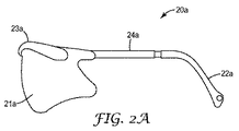
図2Aに示される例示的なアイウェアは、メガネと呼ぶことができる。例示的なメガネ20aは、つる22a(メガネには通常2つのつるが設けられるが、簡略化のため1つだけ示されている)、フレーム23a、及び任意の連結部24a(メガネには通常2つのつるが設けられるが、簡略化のため1つだけ示されている)によって形成されたレンズキャリアを備えている。この例示的なレンズキャリアは、単一レンズ21aを保持する役割を果たす。しかしながら、こうした例示的な実施形態は、2枚以上のレンズを保持するように構成されてもよい及び/又はより多くの又はより少ない構成要素を備えていてもよい。
The exemplary eyewear shown in FIG. 2A can be referred to as glasses.
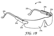
図2Bに示されている例示的アイウェアもまた、メガネと呼ぶことができる。例示的なメガネ20bは、つる22b、レンズ21bをレンズキャリアに固定するように協働する取り付け部分23b、連結部24b、及びブリッジ(nosepieces)25bによって形成されたレンズキャリアを備えている。この例示的なレンズキャリアも同様に、単一レンズ21bを保持する役割を果たす。しかしながら、こうした例示的な実施形態は、2枚以上のレンズを保持するように構成されてもよい及び/又はより多くの又はより少ない構成要素を備えていてもよい。
The exemplary eyewear shown in FIG. 2B can also be referred to as glasses. The
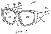
2Cに示されている例示的アイウェアもまた、メガネと呼ぶことができる。例示的なメガネ20cは、つる22c、フレーム23c、レンズ21c及び21dを固定するように協働するフレーム23cの様々な部分、並びにブリッジ25cによって形成されたレンズキャリアを備えている。このレンズキャリアは、2枚のレンズ21c及び21cを保持する役割を果たす。しかしながら、こうした例示的な実施形態は、単一レンズを保持するように構成されてもよい。図2Cの例示的なメガネは、任意のサイドシールド26cも備えている。任意のサイドシールド26cもまた、本明細書に記載されるポリマー材料で作製され得、又は金属スクリーン若しくは任意の好適な構造であることができ、あるいは金属スクリーン若しくは任意の好適な構造を含むことができる。例示的なレンズキャリアも同様に、より多くの又はより少ない構成要素を備えていてもよい。
The exemplary eyewear shown in 2C can also be referred to as glasses. The
図3に示されるアイウェアは、ゴーグルと呼ぶことができる。例示的なゴーグル30は、ストラップ32とフレーム33とを備える(このフレームは、単一の一体部品であることができ、又は例示的なフレーム33へと成形される2つ以上の個々の部品で作製されることができる)。このレンズキャリアは、単一レンズ31を保持する役割を果たす。しかしながら、こうした例示的な実施形態は、2枚以上のレンズを保持するように構成されてもよい及び/又はより多くの又はより少ない構成要素を備えていてもよい。
The eyewear shown in FIG. 3 can be referred to as goggles. The
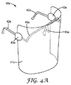
図4Aに示されるアイウェアは、安全シールドと呼ぶことができる。例示的な安全シールド40aは、つる42a、レンズ41aを固定するように協働するつる取り付け部分43a、任意の内部フレーム46a、及びブリッジ45aによって形成されるレンズキャリアを備える。このレンズキャリアはまた、単一レンズ41aを保持する役割を果たす。他の例示的な実施形態において、レンズキャリアは異なる構成を有してもよい。図4Bは別の例示的な安全シールドを示している。図4Bの例示的安全シールド40bは、調節装置47bとフレーム43bとを備えていてもよいヘッドバンド又はヘッドクレードル(head cradle)42bを備えている。このレンズキャリアは、単一レンズ41bを保持する役割を果たす。しかしながら、こうした例示的な実施形態は、その他の好適な構成を有してもよい及び/又はより多くの又はより少ない構成要素を備えていてもよい。図2A〜図4Bに示される例示的な実施形態の様々な構成要素は、所望の場合には変更及び交換されてもよい。
The eyewear shown in FIG. 4A can be referred to as a safety shield. The
開示される1枚又は2枚以上の金属検出可能なレンズを使用することができる例示的アイウェアは、あらゆるタイプのアイウェアであってもよい。いくつかの例示的な実施形態にでは、1枚又は2枚以上のレンズは倍率を有することができるので、度付きアイウェアで使用することができる。他の例示的な実施形態では、1枚又は2枚以上のレンズは度なしであり得る(即ち、測定可能な程度の倍率によって特徴付けられない)。かかる度なしレンズは、保護アイウェアで一般に使用される。いくつかの例示的な実施形態において、例示的アイウェアは、少なくとも1枚の度なしレンズと少なくとも1枚の度付きレンズとを備えていてもよく、又はレンズは、倍率を有するレンズ部分と度なし部分との組み合わせを含んでもよい。 Exemplary eyewear that can use the disclosed one or more metal detectable lenses may be any type of eyewear. In some exemplary embodiments, one or more lenses can have a magnification so that they can be used in prescription eyewear. In other exemplary embodiments, one or more lenses may be insignificant (ie not characterized by a measurable degree of magnification). Such infinite lenses are commonly used in protective eyewear. In some exemplary embodiments, the exemplary eyewear may comprise at least one non-degree lens and at least one degree lens, or the lens may have a lens portion having a magnification and a degree. A combination with a none part may be included.
本明細書に記載されるもののようなレンズキャリアは、本明細書に図示されない構成要素を備えることができることにも留意されたい。種々のその他のタイプのレンズキャリアを、本明細書に記載される金属検出可能なレンズと共に使用することができることにも留意されたい。開示されるレンズは、一般に使用される任意の安全レンズキャリア又はそれらの変形と共に使用することができる。開示される金属検出可能なレンズは、金属検出可能なレンズキャリアと組み合わされることも可能である。例示的な金属検出可能なレンズキャリアは、同一出願人による米国特許出願第12/764,127号、発明の名称「Metal Detectable Lens Carrier」(Donald Seeto)に見出すことができる。 It should also be noted that lens carriers such as those described herein can comprise components not shown herein. It should also be noted that various other types of lens carriers can be used with the metal detectable lenses described herein. The disclosed lens can be used with any commonly used safety lens carrier or variations thereof. The disclosed metal detectable lens can also be combined with a metal detectable lens carrier. An exemplary metal detectable lens carrier can be found in commonly assigned US patent application Ser. No. 12 / 764,127, entitled “Metal Detectable Lens Carrier” (Donald Seto).
金属検出可能なアイウェアの少なくとも一部を検出する方法もまた、本明細書に記載される。1つのかかる例示的方法が図5に示されている。かかる方法の第1の工程(工程52)は、金属検出可能なアイウェア又はその少なくとも一部を提供することである。本明細書の方法において言及される金属検出可能なアイウェアは、少なくとも1枚の金属検出可能なレンズと、レンズキャリアとを備えることができる。金属検出可能なアイウェアを提供する工程は、少なくとも1枚の開示のレンズを備える任意の金属検出可能なアイウェアを提供することを含み得る。前記提供する工程は、例えば、アイウェアを製造する、購入する、又は単純にユーザーに提供することによって達成される。いくつかの実施形態では、金属検出可能なアイウェアは、所望により、金属検出可能なレンズキャリアを備えることも可能である。 A method for detecting at least a portion of metal-detectable eyewear is also described herein. One such exemplary method is shown in FIG. The first step (step 52) of such a method is to provide metal detectable eyewear or at least a portion thereof. The metal detectable eyewear referred to in the methods herein may comprise at least one metal detectable lens and a lens carrier. Providing metal detectable eyewear may include providing any metal detectable eyewear comprising at least one disclosed lens. The providing step is accomplished, for example, by manufacturing, purchasing, or simply providing the user with eyewear. In some embodiments, the metal detectable eyewear can optionally include a metal detectable lens carrier.
次の工程(工程54)は、レンズの少なくとも一部を金属検知器に通すことを含む。金属検知器は、レンズの一部を検出することが可能な任意のタイプの金属検知器を包含することができる。複数の実施形態において、金属検知器は、食品業界、又は他の製造業で一般に使用されるものを包含し得る。使用可能な金属検知器は、製造装置のより大きな部品内に配置されることができ、又は独立型であることができる。 The next step (step 54) involves passing at least a portion of the lens through a metal detector. The metal detector can include any type of metal detector capable of detecting a portion of the lens. In embodiments, metal detectors can include those commonly used in the food industry, or other manufacturing industries. Usable metal detectors can be placed in larger parts of the manufacturing equipment or can be stand alone.
次の工程(工程56)は、レンズの一部を検出することを含む。レンズの一部は、レンズ中の導電材料の一部を検出することによって検出され得る。上述のように、金属検知器は、一般に、レンズの一部を検出するように機能する。複数の実施形態において、検出されるレンズの一部は、約0.08gという小ささであり得る。 The next step (step 56) involves detecting a portion of the lens. A portion of the lens can be detected by detecting a portion of the conductive material in the lens. As described above, metal detectors generally function to detect a portion of a lens. In embodiments, the portion of the lens that is detected can be as small as about 0.08 g.
材料及び方法
特に言及されない限り、全ての化学物質は、Aldrichから入手され、更に精製することなく使用された。特に記載のない限り、実施例に記載される部、百分率、比率などはすべて、重量による。
Materials and Methods Unless otherwise noted, all chemicals were obtained from Aldrich and used without further purification. Unless stated otherwise, all parts, percentages, ratios, etc., given in the examples are by weight.
厚さ3mmのポリカーボネートレンズに、450ÅのTiO2(/2100ÅのAg/900ÅのTiO2をコーティングした。コーティングパラメータは、表1に示される所望のコーティング厚さを得られるようなものであった。次いで、レンズの様々な部分[完全なレンズの半分(1/2レンズ)、15/16インチ(直径0.94インチ)(2.39cm)、又は1/2インチ(直径0.50インチ)(1.27cm)]を試験して、それらが金属検知器によって検出されることができるかを判定した。使用した金属検知器はEriez EZ tech III シリーズH04(Eriez,Erie PA)であった。金属検知器は、1.5mmの鋼球を検出するように較正された。レンズの一部は、検出された(はい)又は検出されない(いいえ)のいずれかであった。レンズの一部がはい*と報告された場合、金属検知器はアラーム(ライト)を作動させたが、レンズの一部を(機械的押出機によって)撥ね出さなかったことを意味する。 A 3 mm thick polycarbonate lens was coated with 450 Ti TiO 2 (/ 2100 A Ag / 900 Ti TiO 2. The coating parameters were such that the desired coating thicknesses shown in Table 1 were obtained. Then various parts of the lens [half full lens (1/2 lens), 15/16 inch (0.94 inch diameter) (2.39 cm), or 1/2 inch (0.50 inch diameter) ( 1.27 cm)] was tested to determine if they could be detected by a metal detector, which was an Eriez EZ tech III series H04 (Eriez, Erie PA). The detector was calibrated to detect a 1.5 mm steel ball, part of the lens was detected (yes) or detected. No (no) it was either. If some of the lens is reported yes *, the metal detector was operated alarm (light), some lenses (by a mechanical extruder) It means that it did not splash.

試料のいくつかに関し、Haze Gardカタログ番号4726(Gardner,Columbia MD)を使用して透過率及びヘイズ(共に%で報告)を測定した。結果を以下の表2に報告する。 For some of the samples, transmission and haze (both reported in%) were measured using Haze Gard catalog number 4726 (Gardner, Columbia MD). The results are reported in Table 2 below.
このように、金属検出可能なレンズの実施形態が開示される。本開示が、開示されたもの以外の実施形態で実施され得ることは当業者に理解されるであろう。開示された実施形態は、図示の目的のために示され、制限のために示されてはおらず、本開示は以下の「特許請求の範囲」によってのみ制限される。 Thus, an embodiment of a metal detectable lens is disclosed. It will be appreciated by persons skilled in the art that the present disclosure may be practiced with embodiments other than those disclosed. The disclosed embodiments are shown for purposes of illustration and not limitation, and the present disclosure is limited only by the following claims.
Claims (20)
第1の表面と第2の表面とを有し、視覚的に透明な材料を含む第1の層と、
視覚的に透明な導電材料の層であり、前記第1の層の前記第1の表面上に配置される第2の層と、
を含み、前記第2の層が、少なくとも約18ジーメンス/mの導電性を有し、0.08gと小さい前記レンズの一部が、直径1.5mmの鋼球を検出するように較正された金属検知器によって検出され得る、金属検出可能なレンズ。 A metal detectable lens,
A first layer having a first surface and a second surface and comprising a visually transparent material;
A second layer of a visually transparent conductive material disposed on the first surface of the first layer;
Wherein the second layer has a conductivity of at least about 18 Siemens / m and a portion of the lens as small as 0.08 g was calibrated to detect a steel ball with a diameter of 1.5 mm. A metal detectable lens that can be detected by a metal detector.
第1の表面と第2の表面とを有し、視覚的に透明な材料を含む第1の層と、
視覚的に透明な導電材料の層であり、前記第1の層の前記第1の表面上に配置される第2の層と、
を含み、前記第2の層が少なくとも約1200Åの厚さであり、
0.08gと小さい前記レンズの一部が、直径1.5mmの鋼球を検出するように較正された金属検知器によって検出され得る、金属検出可能なレンズ。 A metal detectable lens,
A first layer having a first surface and a second surface and comprising a visually transparent material;
A second layer of a visually transparent conductive material disposed on the first surface of the first layer;
Wherein the second layer is at least about 1200 mm thick,
A metal detectable lens wherein a portion of the lens as small as 0.08 g can be detected by a metal detector calibrated to detect a steel ball with a diameter of 1.5 mm.
レンズキャリアと、
請求項1に記載の少なくとも1枚の金属検出可能なレンズと、
を備え、前記レンズキャリアが、前記少なくとも1枚の金属検出可能なレンズを保持するように構成され、前記金属検出可能なアイウェアが、前記少なくとも1枚の金属検出可能なレンズを通して見るユーザーにより装着され得る、金属検出可能なアイウェア。 Metal-detectable eyewear,
A lens carrier,
At least one metal-detectable lens according to claim 1;
The lens carrier is configured to hold the at least one metal detectable lens and the metal detectable eyewear is worn by a user viewing through the at least one metal detectable lens Metal eyewear that can be detected.
金属検出可能なアイウェアの少なくとも一部を提供する工程であって、
前記金属検出可能なアイウェアの一部が、第1の表面と第2の表面とを有し、かつ視覚的に透明な材料を含む第1の層、及び導電材料の層であり前記第1の層の前記第1の表面上に配置される第2の層を含む、
前記金属検出可能なアイウェアの少なくとも一部を提供する工程と、
前記金属検出可能なアイウェアの一部を金属検知器に通す工程と、
前記金属検知器の使用によって前記レンズ中の前記導電材料を検出することによって、前記金属検出可能なアイウェアの一部を検出する工程と、を含む検出方法。 A method of detecting at least a portion of metal-detectable eyewear, the method comprising:
Providing at least a portion of metal-detectable eyewear comprising:
A portion of the metal detectable eyewear is a first layer having a first surface and a second surface and comprising a visually transparent material, and a layer of conductive material, the first layer A second layer disposed on the first surface of the layer of
Providing at least a portion of the metal detectable eyewear;
Passing a portion of the metal detectable eyewear through a metal detector;
Detecting a portion of the metal-detectable eyewear by detecting the conductive material in the lens by use of the metal detector.
Applications Claiming Priority (3)
| Application Number | Priority Date | Filing Date | Title |
|---|---|---|---|
| US12/764,122 | 2010-04-21 | ||
| US12/764,122 US7967435B1 (en) | 2010-04-21 | 2010-04-21 | Metal detectable lens |
| PCT/US2011/033159 WO2011133618A2 (en) | 2010-04-21 | 2011-04-20 | Metal detectable lens |
Publications (2)
| Publication Number | Publication Date |
|---|---|
| JP2013525845A true JP2013525845A (en) | 2013-06-20 |
| JP2013525845A5 JP2013525845A5 (en) | 2014-06-05 |
Family
ID=44169342
Family Applications (1)
| Application Number | Title | Priority Date | Filing Date |
|---|---|---|---|
| JP2013506256A Pending JP2013525845A (en) | 2010-04-21 | 2011-04-20 | Metal detectable lens |
Country Status (8)
| Country | Link |
|---|---|
| US (1) | US7967435B1 (en) |
| EP (1) | EP2561399A4 (en) |
| JP (1) | JP2013525845A (en) |
| CN (1) | CN102939556B (en) |
| AU (1) | AU2011242851B2 (en) |
| BR (1) | BR112012026786A2 (en) |
| TW (1) | TWI503597B (en) |
| WO (1) | WO2011133618A2 (en) |
Families Citing this family (11)
| Publication number | Priority date | Publication date | Assignee | Title |
|---|---|---|---|---|
| US20120105740A1 (en) | 2000-06-02 | 2012-05-03 | Oakley, Inc. | Eyewear with detachable adjustable electronics module |
| US8482488B2 (en) | 2004-12-22 | 2013-07-09 | Oakley, Inc. | Data input management system for wearable electronically enabled interface |
| US7013009B2 (en) | 2001-06-21 | 2006-03-14 | Oakley, Inc. | Eyeglasses with wireless communication features |
| EP2095178B1 (en) | 2006-12-14 | 2015-08-12 | Oakley, Inc. | Wearable high resolution audio visual interface |
| US8342679B2 (en) | 2010-04-21 | 2013-01-01 | 3M Innovative Properties Company | Metal detectable lens carrier |
| WO2014138159A1 (en) * | 2013-03-07 | 2014-09-12 | Oakley, Inc. | Regeneratable ant-fogging element for goggle |
| CN205177388U (en) | 2013-03-15 | 2016-04-20 | 奥克利有限公司 | Eyepiece system |
| CN205691887U (en) | 2013-06-12 | 2016-11-16 | 奥克利有限公司 | Modular communication system and glasses communication system |
| US11925582B2 (en) | 2019-09-09 | 2024-03-12 | Gateway Safety, Inc. | Metal-detectable lens assemblies and protective eyewear including same |
| US11690762B2 (en) * | 2019-09-09 | 2023-07-04 | Gateway Safety, Inc. | Metal-detectable lens assemblies and protective eyewear including same |
| WO2022104440A1 (en) * | 2020-11-20 | 2022-05-27 | Kacavenda Dijana | Protective anti-virus visor with built-in ophthalmic glasses |
Citations (14)
| Publication number | Priority date | Publication date | Assignee | Title |
|---|---|---|---|---|
| JPH06273535A (en) * | 1993-01-21 | 1994-09-30 | Nikka Densoku Kk | Metal detector and remover |
| JPH09318617A (en) * | 1996-05-27 | 1997-12-12 | Fumitomo Kikuchi | Method for determining degree of freshness for foodstuff |
| JPH116985A (en) * | 1997-06-18 | 1999-01-12 | Konica Corp | Spectacle lens having electromagnetic wave shielding effect |
| JPH1173119A (en) * | 1997-03-24 | 1999-03-16 | Konica Corp | Antireflection coat having electromagnetic wave shield effect and optical member having antireflection coat |
| JPH11118765A (en) * | 1997-10-09 | 1999-04-30 | Ishida Co Ltd | Metal detection machine and metal detection system |
| WO2000023275A1 (en) * | 1998-10-20 | 2000-04-27 | Dynamic Products Limited | Laminar plastics film |
| JP2002168757A (en) * | 2000-11-28 | 2002-06-14 | National Institute For Materials Science | Probe for scanning tunneling microscope and method of fabrication |
| JP2003014866A (en) * | 2001-07-03 | 2003-01-15 | Ishida Co Ltd | Metal detector and detecting system |
| JP2003139945A (en) * | 2001-10-31 | 2003-05-14 | Hamamatsu Photonics Kk | Uv ray band pass filter |
| JP2005283835A (en) * | 2004-03-29 | 2005-10-13 | Soichi Ogawa | Electromagnetic wave shielding lens having transparent conductive thin film |
| JP2005345433A (en) * | 2004-06-07 | 2005-12-15 | Anritsu Sanki System Co Ltd | Metal detector |
| JP2009058267A (en) * | 2007-08-30 | 2009-03-19 | Hitachi Aic Inc | Silver deposition film thickness measuring method |
| JP3149893U (en) * | 2009-02-06 | 2009-04-16 | アラム株式会社 | Rubber or plastic gloves |
| JP3151352U (en) * | 2009-04-08 | 2009-06-18 | アラム株式会社 | Spatula for food |
Family Cites Families (34)
| Publication number | Priority date | Publication date | Assignee | Title |
|---|---|---|---|---|
| US4024318A (en) | 1966-02-17 | 1977-05-17 | Exxon Research And Engineering Company | Metal-filled plastic material |
| GB1261242A (en) | 1969-01-28 | 1972-01-26 | Ici Ltd | Improvements in or relating to sun glasses or goggles |
| FR2229777B1 (en) | 1973-05-17 | 1975-08-22 | Ugine Carbone | |
| FR2276601A1 (en) * | 1974-06-27 | 1976-01-23 | France Etat | TAPE FILTERS AND APPLICATION TO THE MANUFACTURING OF PROTECTIVE GLASSES |
| US4071293A (en) | 1974-10-18 | 1978-01-31 | Avery Theodore P | Contact lens and method of making same |
| US3962505A (en) | 1974-10-18 | 1976-06-08 | Avery Theodore P | Plastic contact lens with magnetic embedded metal ring |
| US4222640A (en) | 1977-06-06 | 1980-09-16 | Bononi Walter H | Safety spectacles |
| US4632527A (en) * | 1983-06-03 | 1986-12-30 | American Optical Corporation | Anti-static ophthalmic lenses |
| US5018223A (en) | 1989-09-20 | 1991-05-28 | John R. Gregory | Non-fogging goggles |
| US5023597A (en) | 1990-02-28 | 1991-06-11 | Richard Salisbury | Detection apparatus for safety eyewear |
| CN2068827U (en) * | 1990-04-16 | 1991-01-09 | 卢桂枝 | Goggles |
| US5165992A (en) | 1991-07-02 | 1992-11-24 | Hoya Corporation | Hard coating film and optical elements having such coating film |
| US6177113B1 (en) * | 1995-06-27 | 2001-01-23 | Apv Crepaco, Inc. | Process for detecting plastic or elastomeric contaminants in food processing |
| US6040053A (en) | 1996-07-19 | 2000-03-21 | Minnesota Mining And Manufacturing Company | Coating composition having anti-reflective and anti-fogging properties |
| GB2315698A (en) * | 1996-07-26 | 1998-02-11 | Harold Moore | A moulded tool |
| AU722903B2 (en) | 1996-12-11 | 2000-08-17 | Luxottica Leasing S.P.A. | Electric path frame construction for eyewear |
| US5991072A (en) | 1997-01-28 | 1999-11-23 | 3M Innovation Properties Company | Light filtering lens film |
| US6577358B1 (en) | 1997-06-25 | 2003-06-10 | Dai Nippon Printing Co., Ltd. | Lens film with conductive lens layer or conductive layer |
| WO2000000855A1 (en) | 1998-06-30 | 2000-01-06 | Kimberly-Clark Worldwide, Inc. | Coating composition for reducing reflection and fogging |
| US6932471B2 (en) | 2003-08-06 | 2005-08-23 | Gary M. Zelman | Eyeglasses having magnetically coupled primary lens frame and auxiliary frame |
| US6327087B1 (en) | 1998-12-09 | 2001-12-04 | Canon Kabushiki Kaisha | Optical-thin-film material, process for its production, and optical device making use of the optical-thin-film material |
| US6113482A (en) | 1999-06-10 | 2000-09-05 | Marlen Research Corporation | Metal-detectable elastomeric material for piston seals and the like |
| JP4524877B2 (en) * | 2000-07-17 | 2010-08-18 | コニカミノルタホールディングス株式会社 | Eyeglass lenses |
| US7222727B2 (en) | 2001-02-15 | 2007-05-29 | Integral Technologies, Inc. | Low cost food processing belts and other conveyances manufactured from conductive loaded resin-based materials |
| US6853492B1 (en) | 2003-10-27 | 2005-02-08 | Agilent Technologies, Inc. | Conductive lens |
| US7712469B2 (en) | 2004-04-15 | 2010-05-11 | Sperian Hearing Protection, Llc | Detectable earplug and cord |
| US7294405B2 (en) | 2004-08-26 | 2007-11-13 | 3M Innovative Properties Company | Antiglare coating and articles |
| WO2006093113A1 (en) | 2005-03-03 | 2006-09-08 | Nikon-Essilor Co., Ltd. | Lens for spectacles and method for forming lens for spectacles |
| GB2428629A (en) * | 2005-07-27 | 2007-02-07 | B S Teasdale & Son Ltd | Magnetically detectable bag |
| US7390580B1 (en) | 2005-08-19 | 2008-06-24 | Rubber Fab Gasket & Molding, Inc. | Metal detectable gasket |
| WO2007148348A1 (en) * | 2006-06-19 | 2007-12-27 | Corozite S.P.A. | Non-infringement apparatus |
| US20070298242A1 (en) | 2006-06-26 | 2007-12-27 | University Of Central Florida Research Foundation, Inc. | Lenses having dispersed metal nanoparticles for optical filtering including sunglasses |
| CN200947139Y (en) | 2006-09-01 | 2007-09-12 | 新康电脑科技(苏州)有限公司 | Strong magnetic field eye health glasses |
| DE102008014900A1 (en) * | 2008-03-19 | 2009-09-24 | Rodenstock Gmbh | Coating system for heating optical surfaces and simultaneous reflection reduction |
-
2010
- 2010-04-21 US US12/764,122 patent/US7967435B1/en not_active Expired - Fee Related
-
2011
- 2011-04-20 AU AU2011242851A patent/AU2011242851B2/en not_active Expired - Fee Related
- 2011-04-20 JP JP2013506256A patent/JP2013525845A/en active Pending
- 2011-04-20 BR BR112012026786A patent/BR112012026786A2/en not_active Application Discontinuation
- 2011-04-20 WO PCT/US2011/033159 patent/WO2011133618A2/en active Application Filing
- 2011-04-20 EP EP11772597.8A patent/EP2561399A4/en not_active Withdrawn
- 2011-04-20 CN CN201180019381.2A patent/CN102939556B/en not_active Expired - Fee Related
- 2011-04-21 TW TW100113936A patent/TWI503597B/en not_active IP Right Cessation
Patent Citations (14)
| Publication number | Priority date | Publication date | Assignee | Title |
|---|---|---|---|---|
| JPH06273535A (en) * | 1993-01-21 | 1994-09-30 | Nikka Densoku Kk | Metal detector and remover |
| JPH09318617A (en) * | 1996-05-27 | 1997-12-12 | Fumitomo Kikuchi | Method for determining degree of freshness for foodstuff |
| JPH1173119A (en) * | 1997-03-24 | 1999-03-16 | Konica Corp | Antireflection coat having electromagnetic wave shield effect and optical member having antireflection coat |
| JPH116985A (en) * | 1997-06-18 | 1999-01-12 | Konica Corp | Spectacle lens having electromagnetic wave shielding effect |
| JPH11118765A (en) * | 1997-10-09 | 1999-04-30 | Ishida Co Ltd | Metal detection machine and metal detection system |
| WO2000023275A1 (en) * | 1998-10-20 | 2000-04-27 | Dynamic Products Limited | Laminar plastics film |
| JP2002168757A (en) * | 2000-11-28 | 2002-06-14 | National Institute For Materials Science | Probe for scanning tunneling microscope and method of fabrication |
| JP2003014866A (en) * | 2001-07-03 | 2003-01-15 | Ishida Co Ltd | Metal detector and detecting system |
| JP2003139945A (en) * | 2001-10-31 | 2003-05-14 | Hamamatsu Photonics Kk | Uv ray band pass filter |
| JP2005283835A (en) * | 2004-03-29 | 2005-10-13 | Soichi Ogawa | Electromagnetic wave shielding lens having transparent conductive thin film |
| JP2005345433A (en) * | 2004-06-07 | 2005-12-15 | Anritsu Sanki System Co Ltd | Metal detector |
| JP2009058267A (en) * | 2007-08-30 | 2009-03-19 | Hitachi Aic Inc | Silver deposition film thickness measuring method |
| JP3149893U (en) * | 2009-02-06 | 2009-04-16 | アラム株式会社 | Rubber or plastic gloves |
| JP3151352U (en) * | 2009-04-08 | 2009-06-18 | アラム株式会社 | Spatula for food |
Also Published As
| Publication number | Publication date |
|---|---|
| AU2011242851B2 (en) | 2015-08-13 |
| EP2561399A4 (en) | 2014-04-30 |
| CN102939556B (en) | 2014-10-29 |
| US7967435B1 (en) | 2011-06-28 |
| TW201200932A (en) | 2012-01-01 |
| EP2561399A2 (en) | 2013-02-27 |
| BR112012026786A2 (en) | 2017-10-17 |
| WO2011133618A2 (en) | 2011-10-27 |
| CN102939556A (en) | 2013-02-20 |
| AU2011242851A1 (en) | 2012-11-15 |
| WO2011133618A3 (en) | 2012-01-05 |
| TWI503597B (en) | 2015-10-11 |
Similar Documents
| Publication | Publication Date | Title |
|---|---|---|
| JP2013525845A (en) | Metal detectable lens | |
| TWI503594B (en) | Metal detectable lens carrier | |
| JP6367834B2 (en) | Optical element for correcting color blindness | |
| JP2014527645A (en) | Optical element for correcting color blindness | |
| JP6414362B2 (en) | Polarizing laminate and glasses | |
| US20160231594A1 (en) | Optical article with gradient photochromism | |
| US20200376804A1 (en) | TAC Primer Coating with Improved Adhesion | |
| US10921502B2 (en) | Eyewear article with interference filter | |
| US20160266290A1 (en) | Optical Device with a Functionalised Coating and Method for Such Optical Device | |
| US8029131B2 (en) | Invertible eyewear | |
| US20060050225A1 (en) | Multifocal polarized sunglasses and lenses | |
| CN210155448U (en) | Glasses | |
| JP2006328156A (en) | Protecting film and method for producing the same | |
| US20200050024A1 (en) | Ophthalmic article | |
| US11953650B2 (en) | Sheet and method for producing sheet | |
| EP3690502B1 (en) | Optical sheet and optical component | |
| CN220289978U (en) | Eye-protecting glasses lens for increasing vision | |
| US11345132B2 (en) | Optical sheet and optical component | |
| CN209248058U (en) | A kind of microwire multilayer film vacuum coating lens | |
| JP6516059B1 (en) | Optical sheet and optical component | |
| US20200249378A1 (en) | Optical sheet and optical component | |
| JP6202294B2 (en) | Sight adjustment sheet and method for manufacturing the same | |
| 백연경 et al. | Fabrication of Bimetalic (Au-Ag) Patterns with Dielectric Interlayers for Effective Surface-Enhanced Raman Scattering (SERS) Based Detection | |
| US20160297155A1 (en) | Methods for Manufacturing Articles Comprising Photochromic Film | |
| KR20190067790A (en) | Temporary polarization patch |
Legal Events
| Date | Code | Title | Description |
|---|---|---|---|
| A521 | Request for written amendment filed |
Free format text: JAPANESE INTERMEDIATE CODE: A523 Effective date: 20140418 |
|
| A621 | Written request for application examination |
Free format text: JAPANESE INTERMEDIATE CODE: A621 Effective date: 20140418 |
|
| A977 | Report on retrieval |
Free format text: JAPANESE INTERMEDIATE CODE: A971007 Effective date: 20150220 |
|
| A131 | Notification of reasons for refusal |
Free format text: JAPANESE INTERMEDIATE CODE: A131 Effective date: 20150303 |
|
| A521 | Request for written amendment filed |
Free format text: JAPANESE INTERMEDIATE CODE: A523 Effective date: 20150528 |
|
| A02 | Decision of refusal |
Free format text: JAPANESE INTERMEDIATE CODE: A02 Effective date: 20151027 |