JP2013504427A - Energy conversion method, energy conversion apparatus, and welding apparatus - Google Patents
Energy conversion method, energy conversion apparatus, and welding apparatus Download PDFInfo
- Publication number
- JP2013504427A JP2013504427A JP2012528188A JP2012528188A JP2013504427A JP 2013504427 A JP2013504427 A JP 2013504427A JP 2012528188 A JP2012528188 A JP 2012528188A JP 2012528188 A JP2012528188 A JP 2012528188A JP 2013504427 A JP2013504427 A JP 2013504427A
- Authority
- JP
- Japan
- Prior art keywords
- arc
- battery
- energy
- capacitor
- switch
- Prior art date
- Legal status (The legal status is an assumption and is not a legal conclusion. Google has not performed a legal analysis and makes no representation as to the accuracy of the status listed.)
- Pending
Links
Images


Classifications
-
- B—PERFORMING OPERATIONS; TRANSPORTING
- B23—MACHINE TOOLS; METAL-WORKING NOT OTHERWISE PROVIDED FOR
- B23K—SOLDERING OR UNSOLDERING; WELDING; CLADDING OR PLATING BY SOLDERING OR WELDING; CUTTING BY APPLYING HEAT LOCALLY, e.g. FLAME CUTTING; WORKING BY LASER BEAM
- B23K9/00—Arc welding or cutting
- B23K9/10—Other electric circuits therefor; Protective circuits; Remote controls
- B23K9/1081—Arc welding by means of accumulated energy
-
- B—PERFORMING OPERATIONS; TRANSPORTING
- B23—MACHINE TOOLS; METAL-WORKING NOT OTHERWISE PROVIDED FOR
- B23K—SOLDERING OR UNSOLDERING; WELDING; CLADDING OR PLATING BY SOLDERING OR WELDING; CUTTING BY APPLYING HEAT LOCALLY, e.g. FLAME CUTTING; WORKING BY LASER BEAM
- B23K9/00—Arc welding or cutting
- B23K9/32—Accessories
-
- B—PERFORMING OPERATIONS; TRANSPORTING
- B23—MACHINE TOOLS; METAL-WORKING NOT OTHERWISE PROVIDED FOR
- B23K—SOLDERING OR UNSOLDERING; WELDING; CLADDING OR PLATING BY SOLDERING OR WELDING; CUTTING BY APPLYING HEAT LOCALLY, e.g. FLAME CUTTING; WORKING BY LASER BEAM
- B23K9/00—Arc welding or cutting
- B23K9/095—Monitoring or automatic control of welding parameters
- B23K9/0953—Monitoring or automatic control of welding parameters using computing means
-
- B—PERFORMING OPERATIONS; TRANSPORTING
- B23—MACHINE TOOLS; METAL-WORKING NOT OTHERWISE PROVIDED FOR
- B23K—SOLDERING OR UNSOLDERING; WELDING; CLADDING OR PLATING BY SOLDERING OR WELDING; CUTTING BY APPLYING HEAT LOCALLY, e.g. FLAME CUTTING; WORKING BY LASER BEAM
- B23K9/00—Arc welding or cutting
- B23K9/10—Other electric circuits therefor; Protective circuits; Remote controls
- B23K9/1006—Power supply
-
- G—PHYSICS
- G01—MEASURING; TESTING
- G01R—MEASURING ELECTRIC VARIABLES; MEASURING MAGNETIC VARIABLES
- G01R31/00—Arrangements for testing electric properties; Arrangements for locating electric faults; Arrangements for electrical testing characterised by what is being tested not provided for elsewhere
- G01R31/36—Arrangements for testing, measuring or monitoring the electrical condition of accumulators or electric batteries, e.g. capacity or state of charge [SoC]
- G01R31/3644—Constructional arrangements
- G01R31/3646—Constructional arrangements for indicating electrical conditions or variables, e.g. visual or audible indicators
-
- H—ELECTRICITY
- H02—GENERATION; CONVERSION OR DISTRIBUTION OF ELECTRIC POWER
- H02J—CIRCUIT ARRANGEMENTS OR SYSTEMS FOR SUPPLYING OR DISTRIBUTING ELECTRIC POWER; SYSTEMS FOR STORING ELECTRIC ENERGY
- H02J7/00—Circuit arrangements for charging or depolarising batteries or for supplying loads from batteries
- H02J7/0047—Circuit arrangements for charging or depolarising batteries or for supplying loads from batteries with monitoring or indicating devices or circuits
- H02J7/0048—Detection of remaining charge capacity or state of charge [SOC]
Landscapes
- Engineering & Computer Science (AREA)
- Physics & Mathematics (AREA)
- Plasma & Fusion (AREA)
- Mechanical Engineering (AREA)
- Theoretical Computer Science (AREA)
- General Physics & Mathematics (AREA)
- Generation Of Surge Voltage And Current (AREA)
- Arc Welding Control (AREA)
Abstract
本発明は蓄電器(2)のエネルギをアーク(6)の操作のために変換する方法であって、電力ユニット(3)と、アーク(6)を操作する電流を設定するための入力および/出力装置(5)とを、エネルギの変換に使用する方法および装置並びに溶接装置に関し、ユーザに蓄電器(2)の状態の情報を提供可能とするために、アーク(6)の操作のための残り時間を、蓄電器(2)の所定の容量、および、入出力装置(5)において設定された電流の値を使用して算出し、その時間対応する表示ユニット(27)に表示する。 The present invention is a method for converting the energy of a battery (2) for operation of an arc (6), the input and / or output for setting a power unit (3) and a current for operating the arc (6). The time remaining for the operation of the arc (6) in order to be able to provide the user with information on the state of the battery (2) with respect to the method and apparatus for using the device (5) for energy conversion and the welding device. Is calculated using the predetermined capacity of the battery (2) and the current value set in the input / output device (5) and displayed on the display unit (27) corresponding to the time.
Description
本発明は、アークの操作のための蓄電器のエネルギを変換するための方法であって、電源ユニットとアークを操作するために電流を設定する入出力装置とが使用されてエネルギを変換する方法に関する。 The present invention relates to a method for converting the energy of a battery for the operation of an arc, wherein the power source unit and an input / output device for setting a current to operate the arc are used to convert the energy. .
本発明は、さらに、アークを操作するために蓄電器のエネルギを変換する装置、および、アークを操作するために電流を設定する入出力装置に関する。 The present invention further relates to a device for converting energy of a battery to operate an arc, and an input / output device for setting a current to operate the arc.
最後に、本発明は、蓄電器と、アークを発生するトーチと、入出力装置と、アークを操作するために蓄電器のエネルギを変換する装置とを含む溶接装置にも関する。 Finally, the present invention also relates to a welding apparatus that includes a capacitor, a torch that generates an arc, an input / output device, and a device that converts the energy of the capacitor to operate the arc.
可搬性を促進するために、前記装置を使用して実行され得る適用例のような、適当な装置の電子システムまたはパワーエレクトロニクスに電気エネルギを供給するための電源として蓄電器を使用すると一般に理解されている。そのエネルギが限定されているので、蓄電器は定期的に再充電されなければならない。 It is generally understood to use a capacitor as a power source for supplying electrical energy to an electronic system or power electronics of a suitable device, such as an application that can be implemented using the device, to facilitate portability. Yes. Since its energy is limited, the battery must be recharged periodically.
溶接装置のような金属加工用装置における蓄電器の使用は、例えば、DE2650522A1およびGB2316244Aの明細書から公知である。 The use of capacitors in metalworking equipment such as welding equipment is known, for example, from the specifications of DE 2650522A1 and GB2316244A.
US2005/0109748A1は、溶接エネルギまたはアークを生成する電源をそれぞれ有する溶接装置を記載する。蓄電器の電圧は、ステップアップコンバータによって中間電圧に変換され、続いて、下流のステップダウンコンバータによってアークに必要な電圧に降圧される。蓄電器は、充電装置を使用して再充電できる。前記充電装置は、独立したユニットであり、溶接装置に組み込まれてもよく、外部装置として蓄電器に接続されてもよい。アークのためのエネルギが2段階で生成されることは、ステップアップコンバータとステップダウンコンバータの両方においてスイッチング損失が生じ、それにより効率が低下するので、不利である。加えて、ステップダウンコンバータは、昇圧した中間電圧をアーク電圧に変換する必要があるので、大きな電圧差によりスイッチング損失が増大する。 US 2005/0109748 A1 describes a welding apparatus each having a power source for generating welding energy or arc. The voltage of the battery is converted to an intermediate voltage by the step-up converter, and then stepped down to the voltage required for the arc by the downstream step-down converter. The battery can be recharged using a charging device. The charging device is an independent unit, may be incorporated in a welding device, and may be connected to a capacitor as an external device. The generation of energy for the arc in two stages is disadvantageous because switching losses occur in both step-up and step-down converters, thereby reducing efficiency. In addition, since the step-down converter needs to convert the boosted intermediate voltage into an arc voltage, switching loss increases due to a large voltage difference.
US2009/008374A1およびUS2007/181547は、バッテリの充電状態が表示される可搬電池駆動溶接装置を記載している。 US2009 / 008374A1 and US2007 / 181547 describe portable battery-driven welding devices in which the state of charge of the battery is displayed.
また、JP10−272563AおよびJP2003−028939は、ユーザに関係するバッテリの充電容量の情報が提供される可搬電池駆動溶接装置を記載している。 JP10-272563A and JP2003-028939 describe portable battery-driven welding apparatuses in which information on the charging capacity of a battery related to a user is provided.
本発明の課題は、ユーザがエネルギの充電状態の情報を得られる上述の方法および上述の装置の創成である。公知の方法および装置の欠点は、回避または少なくとも低減されなければならない。 The subject of the present invention is the creation of the above-described method and the above-mentioned device, which allows the user to obtain information on the state of charge of energy. The disadvantages of the known methods and devices must be avoided or at least reduced.
本発明の他の課題は、それによってユーザが蓄電器の限定されたエネルギを使用するための理想的エネルギ管理の提供を受けられるような、溶接装置およびそれにより実行され得る方法を創成することである。 Another object of the present invention is to create a welding apparatus and a method that can be performed thereby, whereby the user can be provided with ideal energy management for using the limited energy of the battery. .
本発明の課題は、アークの操作のために残っている時間を計算し、蓄電器の所定の容量に基づく設定電流、および、入出力装置に設定された電流の値と共に表示する、上述の方法によって解決される。溶接装置用のアークを操作する場合、前記パラメータは、電流が設定されたときに溶接のためにまだ残っている時間である残り溶接時間であろう。ここで、装置を始動したときに、既にユーザは、蓄電器をあとどのくらいの長さ使用できるか、つまり、ユーザがあとどのくらい溶接できるかについて、最初の情報を得ている。 The object of the present invention is to calculate the remaining time for the operation of the arc and display it together with the set current based on the predetermined capacity of the capacitor and the value of the current set in the input / output device. Solved. When operating an arc for a welding apparatus, the parameter would be the remaining welding time, which is the time still remaining for welding when the current is set. Here, when the device is started, the user already has initial information on how long the battery can be used, i.e. how much more the user can weld.
有利にも、計算値に基づく前記情報は、調節または推定され、アークの操作中、つまり、エネルギを消費している間、表示される。 Advantageously, the information based on the calculated values is adjusted or estimated and displayed during the operation of the arc, i.e. while consuming energy.
所定の時間間隔で残り時間の値の調節が行われ、それぞれの残り時間が記憶されるのであれば、アークの操作のための電流の開始または変更のとき、記憶した値によってより正確な計算が有意にも行われる。 If the remaining time values are adjusted at predetermined time intervals and each remaining time is memorized, the stored value will give a more accurate calculation when starting or changing the current for the operation of the arc. Significantly done.
他の利点は、コントローラを有する蓄電器の使用であり、それにより計算の正確性が促進される。 Another advantage is the use of a capacitor with a controller, which facilitates calculation accuracy.
本発明の課題は、また、アークの操作のための残り時間を、所定の蓄電器の容量と入出力装置に設定されたアークを操作する電流のための値とに基づいて算出する装置と、残り時間の計算値を表示するディスプレイユニットとが設けられた、上述の装置によっても達成される。それによりもたらされる利点およびさらなる利点は、上述の利点および以下の記載に見られる。 Another object of the present invention is to calculate a remaining time for arc operation based on a predetermined capacitor capacity and a value for an electric current for operating the arc set in the input / output device, and a remaining time This is also achieved by the above-described device provided with a display unit for displaying the calculated value of time. Advantages and further advantages resulting therefrom are found in the above-mentioned advantages and in the following description.
有利には、蓄電器を再充電する装置が、蓄電器の充電プロセスがユーザに伝達される情報に基づいて迅速且つタイミングよく実行できるように設けられる。 Advantageously, an apparatus for recharging the capacitor is provided so that the charging process of the capacitor can be performed quickly and in a timely manner based on information communicated to the user.
入出力装置には、蓄電器の充電状態を表示する発光ダイオードが設けられる。 The input / output device is provided with a light emitting diode that displays the state of charge of the battery.
さらに、充電装置をオンおよびオフするための設定要素を、入出力装置に設け得る。 Further, a setting element for turning on and off the charging device may be provided in the input / output device.
最後に、本課題は、上述の方法を実行するように設計され、或いは、上述の装置を有する、上述の溶接装置によっても解決される。 Finally, this problem is also solved by the above-described welding apparatus designed to carry out the above-described method or having the above-described apparatus.
本発明は、添付の概略図の助けを借りて、より詳細に説明される。 The invention is explained in more detail with the help of the accompanying schematic drawings.
前置きとして、実施形態の同じ部分は同じ参照記号によって示されることを注記する。 As a preface, it is noted that the same parts of the embodiments are denoted by the same reference symbols.
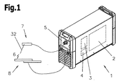
図1には、少なくとも1つの蓄電器2と、電力ユニット3と、制御装置4と、入出力装置5とを含む装置1が示されている。装置1は、制御装置4によって制御されたアーク6を形成するように構成されている。よって、装置1は、例えば、溶接装置、切断装置、清掃装置またははんだ付け装置として使用できる。そのような装置1のトーチ7の冷却のような細部は、それが従来技術から公知であるので、より詳細には説明しない。
FIG. 1 shows a
アーク6のための電流は、トーチ7に移動させられ、または、電極ホルダに保持された電極32とそれぞれの工作物8との間に生成される。いくつかの部品からなる工作物8も、装置1に接続される。したがって、電流は、蓄電器2から供給されて電力ユニット3から提供される。さらに、電流およびさらなるパラメータは、適用可能であれば、入出力装置5において調節または制御され得る。このため、入出力装置5は、制御装置4に接続されている。好ましくは、電力ユニット3は、出力に、それを介してトート7または工作物8を接続できるように、ポートまたはブシュが設けられる。よって、電力ユニット3は、例えば、以下の実施形態において説明するように溶接プロセスが実行できるように、蓄電器2に蓄えられたエネルギを変換する。
The current for the
蓄電器2が制限された範囲で利用可能であるために、電力ユニット3のアーク6の操作のためにステップダウンコンバータを使用して、過渡電圧を抑制する方法で蓄電器に接続されたステップダウンコンバータの少なくとも1つのスイッチ9のスイッチング手順を実行することにより、最小限のスイッチング損失でアーク6にエネルギが提供される。このために、過渡電圧を抑制したスイッチング手順を実行するためのスナバ回路10がステップダウンコンバータに組み込まれている。
Since the
今から、スナバ回路10を含む電力ユニット3を、図2および3の助けを借りて説明する。ステップダウンコンバータの基本的構成要素は、スイッチ9および11およびインダクタ12である。これは、同期変流器とも呼ばれ、同期ステップダウンコンバータとして使用される。効率的に、つまり、およそ99%の効率でアーク6用のエネルギを生成するために、スイッチ9は、スイッチオン手順での過渡電圧抑制およびスイッチオフ手順での過渡電圧抑制の両方を果たすように、スナバ回路10に結線される。このように、非常に小さいエネルギが熱に変換され、それにより、電力ユニット3の電子部品の最小限度の冷却だけが要求される。したがって、要求される電力ユニット3のスペースも最小限に低減される。
From now on, the
この実施形態において、スナバ回路10は、キャパシタおよびインダクタのような蓄電要素、並びに、ダイオードを備えると認められる。通常、ダイオードは、電流の向きを制御し、それにより、蓄電器2のエネルギを、最小限のスイッチング損失で、少なくともスイッチ9のスイッチング動作において、溶接プロセス、切断プロセスまたは清掃プロセスのアーク6に必要なエネルギに変換する。
In this embodiment, the
スイッチオン用スナバは、2つの回路に分割され、第1の回路は、スイッチ9に直列に接続されたインダクタ13からなり、第2の回路は、キャパシタ14およびダイオード15により構成される。第2の回路は、制御ユニット16によって能動的に制御される。第1の回路は、全体として能動的なスイッチオン時の過渡電圧抑制がなされるように、第2の回路を介して間接的に能動制御される。
The switch-on snubber is divided into two circuits. The first circuit includes an
制御ユニット16は、蓄電器2に接続された入力側のスイッチ9と同様のスイッチ17により形成された最も簡単な形態である。この場合、スイッチ17もまた、過渡電圧抑制される。具体的には、スイッチオフ時の過渡電圧抑制は、キャパシタ18およびダイオード19を介して達成され、スイッチオン時の過渡電圧抑制は、インダクタ20および21を介して達成される。
The
スイッチ9のためのスイッチオフ時の過渡電圧抑制は、スイッチ17と同様にキャパシタ22およびダイオード23を介して達成される。ダイオード23は、スイッチ9がオンされたときに、スイッチ9を介したキャパシタ22の制御されない充電を抑止する。
The transient voltage suppression when the
スイッチ11のための過渡電圧抑制は、従来技術から公知の同期ステップダウンコンバータの基本動作の原則から自動的に達成されるので、必要ではない。
Transient voltage suppression for
溶接装置1の制御装置4によって同期コンバータの制御に応じて能動的に制御されるスイッチング手順におけるスイッチオン時およびスイッチオフ時の過渡電圧抑制の機能は、以下の初期状態を基礎として詳細に説明される。
The function of suppressing the transient voltage at the time of switching on and switching off in the switching procedure actively controlled according to the control of the synchronous converter by the control device 4 of the
スイッチ9は開、スイッチ11は閉、キャパシタ14,18および22並びにインダクタ20,21および13は放電済み。
前記初期状態によれば、出力電流Iaまたは溶接エネルギは、スイッチ11およびインダクタ12で形成された電気回路を介して供給され、スイッチ11の電圧は実質的にゼロである。続いて、インダクタ12は放電される。次のステップにおいて、インダクタ12を再充電するために、スイッチ9がオンされてスイッチ11が過渡電圧抑制されてスイッチオフされる。
According to the initial state, the output current Ia or welding energy is supplied via an electric circuit formed by the
スイッチ9をスイッチオンするとき、スイッチオン時の過渡電圧抑制は、本発明にしたがって、スイッチオン時にスイッチ9の自己キャパシタンスが再充電されるだけでよいように機能する。よって、少ない、無視できるスイッチオン損失だけがもたらされる。これは、スイッチオン時に電流の増加を電流増加がインダクタ13の大きさに応じて連続的に生じるように制限するスイッチ9に直列に接続されたインダクタ13によって達成される。このため、最低限のスイッチング損失が出力電流Iaの僅かな量によって生じるだけである。
When the
前記電流の増加は、インダクタ13を通して流れる電流が出力電流Iaと同じ程度に大きい限り継続する。つまり、電流の制限のために、出力電流Iaスイッチ9からの出口に対して全体に遅れて流れる。よって、電流は、スイッチ11に並列に接続したダイオード15を介した出力にはもはや流れず、キャパシタ15がスイッチと並列に再充電される。再充電は、前記キャパシタ14に直列に接続したインダクタ13を介して実行される。これは、結節点K1の電圧を遅れて連続的またはゆっくりと供給電圧、つまり、蓄電器2の電圧まで上昇させる。
The increase in current continues as long as the current flowing through the
さらに、このゆっくりとした電圧上昇によって、スイッチ9およびスイッチ11の両方における電圧の尖鋭な上昇が防止され、スイッチ9または11の望まざる短期のスイッチングが防止される。特に、スイッチ9をオンするとスイッチ11もオンされることが防止される。ここで、溶接エネルギが蓄電器2により直接供給されるいわゆる「導通フェーズ」に言及する。これは、供給電圧が結節点K1に印加される場合である。
In addition, this slow voltage rise prevents a sharp rise in voltage at both
「導通状態」の間、続くスイッチオフ時過渡電圧抑制および次のスイッチオン時過渡電圧抑制のための適切な準備がなされる。「導通状態」の中で「再充電状態」を実行する間に、キャパシタ14,18および22が制御ユニット16の作動、つまり、スイッチ17のオンにより充電される。制御ユニット16の動作の最初に可能な時間点は、供給電圧が結節点K1に印加されたときである。スイッチ17は、キャパシタ14に半分の供給電圧が印加されている限りオンされたままである。さらに、キャパシタ14よりも大きさが小さいキャパシタ22および18は、この時間の間にインダクタ21およびダイオード24を介して完全に充電される。前記インダクタ21およびダイオード24は、キャパシタ18とキャパシタ22との間に配設され、キャパシタ18,22の両方が同じ充電電流IL2で充電される。インダクタ21は、等しい大きさのキャパシタ18および22の充電時間をそれらが同時に等しく供給電圧まで充電されるように制御する。キャパシタ18および22は、遅くとも、キャパシタ14における供給電圧の半分に達するのに必要な時間内に充電される。それにしたがって、インダクタ21の大きさが決められる。さらに、インダクタ21およびダイオード24は、キャパシタ18および22を充電中直列に接続する。スイッチオフ時の過渡電圧抑制を達成するために、キャパシタ18およびダイオード19、または、キャパシタ22およびダイオード23が互いに独立して作用する。
Appropriate provisions are made for subsequent switch-off transient voltage suppression and subsequent switch-on transient voltage suppression during the “conducting state”. While the “recharging state” is executed in the “conducting state”, the
この時間の間、エネルギは、キャパシタ13の充電電流IL1に応じて、スイッチ17に直列に接続されたインダクタ20の中に保存される。
During this time, energy is stored in the
スイッチ17は、キャパシタ18および22が完全に充電され、キャパシタに半分の供給電圧が印加される。充電されたキャパシタ18およびダイオード19は、スイッチ17のためのスイッチオフ時の過渡電圧抑制の機能を果たす。スイッチングの際、キャパシタ18により供給電圧が出力側にも印加され、それにより、スイッチ17は、十分に無電位または電位差なしにスイッチオフまたは開放され得る。そして、キャパシタ18の完全な放電は、インダクタ20を介してキャパシタ14または出力に作用する。したがって、インダクタ21、ダイオード19およびダイオード25により、この中間保存されたエネルギは失われない。キャパシタ18は、キャパシタ22がさらに供給電圧に維持されている間に放電する。
In the
スイッチ17をオフすると、キャパシタ14は、インダクタ20の中に保存されたエネルギで供給電圧まで再充電される。これは、インダクタ20、キャパシタ14およびダイオード25で形成された電気回路を介して行われる。インダクタ20は、スイッチ17がオフされるときにキャパシタ14を供給電圧まで再充電するために、スイッチ17のスイッチオン時間の間に十分なエネルギが保存されるような大きさである。
When
最後に、キャパシタ14における供給電圧に達して、「導通フェーズ」の間に「再充電フェーズ」も完了される。したがって、「導通フェーズ」は、それがスイッチ9のためのスイッチオフ時の過渡電圧抑制のために設けられているので、やはり完了できる。加えて、スイッチ9をオフするときのスイッチオン時の過渡電圧抑制もスイッチ9の次のスイッチオン手順のために略同時に提供されるように、インダクタ13からのエネルギの除去も提供されている。
Finally, the supply voltage at the
スイッチ9をオフする際、スイッチオフ時の過渡電圧抑制は、スイッチ17と同様に、充電されたキャパシタ22によりダイオード23を介してスイッチ9の出力側または結節点K2に供給電圧を印加することによって、スイッチ9における電圧降下または電位差が十分にもたらされ、それにより損失なくスイッチオフされ得るように行われる。
When the
したがって、電流は、蓄電器2からスイッチ9を介してインダクタ13に流れ込まず、それらに保存されるエネルギが有意にも完全に放電され得る。これは、キャパシタ22を完全に放電することにより、結節点K2における電圧がダイオード23を介して出口まで連続的に減少するように行われる。また、スイッチ9をオフするとき、キャパシタ14は放電され、結節点K1における電圧に影響する。結節点K1における電圧は、キャパシタ22と比べてより大きいキャパシタ14によって、結節K2におけるよりもゆっくりと減少する。したがって、インダクタ13に対し、いわゆる負の電圧−時間面積が適用され、それにより、電流は、インダクタ13における電圧の極性がより早く放電したキャパシタ22に応じて反転するので、インダクタ13のために減少する。よって、結節点K2またはスイッチ9の出力側における電位は、キャパシタ22が放電した後、有意にもゼロであり、前記結節点K2における電位は、ダイオード26により維持される。インダクタ13における負の電圧−時間面積は、インダクタ13の放電がもたらす出力に供給される電流を生じる。よって、インダクタ13およびキャパシタ14のエネルギは、有意にも損失なく、出力電流Iaに供給される。故に、スイッチオン時の過渡電圧抑制は、スイッチ9の次のスイッチオン手順のために再度適用できる。したがって、スイッチ9をオフすると、出力電流Iaが遮断されないように、今度はスイッチ11がスイッチオンされる。具体的には、これは、結節点K1における電圧が有意にもゼロまで低下したときに起こる。よって、スイッチオン時の過渡電圧抑制が提供される。ここで、初期条件が再現される。これは、溶接エネルギが要求される限り繰り返される。
Therefore, current does not flow from the
典型的には、電力ユニット3は、蓄電器2から溶接エネルギを提供するために使用され、蓄電器2の容量に応じて制限されたエネルギをユーザが利用できる。
Typically, the
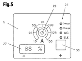
したがって、本発明によれば、利用可能なエネルギまたはそれから導出されるパラメータは、入出力装置5の図4および5に係るディスプレイユニット27上に表示される。好ましくは、蓄電器2の容量および構成要素28を使用して設定されるアーク6を生成するための電流から、前記電流のためにどのぐらいの長さのエネルギが十分であるかが算出される。パラメータ、特に、利用可能時間、つまり、残っている時間の算出は、例えば、以下に説明するように実行される。
Therefore, according to the invention, the available energy or the parameters derived therefrom are displayed on the
従来技術に係る蓄電器2には、いわゆる「充電状態」(SOC)および/または「劣化状態」(SOH)コントローラが組み込まれている。装置1の制御装置4によれば、前記コントローラは、典型的には、蓄電器2の容量に有意に対応する電流充電状態を提供する。さらに、制御装置4は、また、アーク6のために設定された電流を把握する。効果的に使用できる蓄電器2の容量が適用された負荷に大きく依存するため、前記電流が要求される。適用された負荷は、設定された電流に対応する。例えば、高い溶接電流での溶接において、蓄電器2の容量は、中程または低い溶接電流での溶接に比べて早く消耗する。よって、蓄電器2の容量およびアーク6を操作するための電流は、計算の基礎としての役目を果たす。
The
例えば、装置1を始動したとき、設定した電流を流せる時間は、電流および容量から計算され、ディスプレイユニット27上に表示される。これは、残り時間、または、溶接装置の場合には残り溶接時間と呼ばれる。アーク6を操作するための電流、特に、溶接電流が変化した時、残り溶接時間もそれにしたがって調節される。溶接装置の始動時には、溶接プロセスが未だ実行されていないので、表示された残りの溶接時間は、参考値としてのみ役目を果たす。ここでは、実際のエネルギ消費は、未だ計算に入れられていない。これは、特に、アーク6の長さ、使用される溶接電極、適切な溶接用途等に依存する。
For example, when the
溶接プロセスが実行されるとき、制御装置4は、実際の溶接電流と、溶接電圧または電流と、蓄電器2の電圧との値に基づいて、ある時間の実際のエネルギ消費を算出する。前記先のエネルギ消費に基づいて、さらなるエネルギ消費が推定でき、それにより、残り溶接時間溶接、つまり、まだ可能な時間が調節されて、新しい値がディスプレイユニット27に表示され得る。これは、5秒毎、30秒毎または60秒毎のような一定の時間間隔で、アーク6の操作の間になされ得る。好ましくは、新しい溶接プロセスが開始、溶接電流が変化、または、装置1がオフされれば、最後に算出した残り溶接時間が、ディスプレイユニット27に表示される。
When the welding process is performed, the control device 4 calculates the actual energy consumption for a certain time based on the values of the actual welding current, the welding voltage or current, and the voltage of the
さらに、少なくとも最後に算出した値は、前記値が、次に装置を始動したときに、ディスプレイユニット27に表示にされるように記憶されてもよい。
Furthermore, at least the last calculated value may be stored such that the value is displayed on the
残り溶接時間の算出をさらに正確に実行するために、一定の時間間隔で検出された実際の値が、例えば、溶接プロセスの間に記憶される。よって、溶接プロセスに続いて、溶接プロセスの間に消費されるエネルギが、それらから算出され得、前記エネルギ消費の値が溶接プロセスの間に溶接電流を設定するのに割り当てられる。溶接プロセスを同じ溶接電流の設定を使用してある回数実行するとき、エネルギ消費の平均値が使用される。実行されるそれぞれの溶接プロセスのために必要とされる溶接時間も、また記録されるので、前記時間の平均を算出できる。このように、ライブラリが外見的に形成され得、その中でエネルギ消費の平均値は、例えば溶接電流の複数の可能な設定のための所定時間の間に記録され得る。したがって、そのようなライブラリは、溶接プロセスが実行する毎に更新され得る。このように、溶接装置1を始動したとき、または、溶接電流を変化させたときに、設定した溶接電流によるエネルギ消費が、有意にも前記ライブラリの経験的な値から知得される。よって、蓄電器の容量およびライブラリに記録した溶接プロセス当たりのエネルギ消費から、幾つの溶接プロセスが設定した溶接電流および蓄電器2の利用可能な容量を使用して実行できるかを算出できる。エネルギ消費に応じて、関連する溶接時間もまたライブラリに記録されるので、残り溶接時間が計算して、ディスプレイユニット27に表示され得る。
In order to perform the calculation of the remaining welding time more accurately, the actual values detected at regular time intervals are stored, for example, during the welding process. Thus, following the welding process, the energy consumed during the welding process can be calculated therefrom, and the value of said energy consumption is assigned to set the welding current during the welding process. When performing the welding process a number of times using the same welding current setting, the average value of energy consumption is used. The welding time required for each welding process performed is also recorded so that an average of the times can be calculated. In this way, a library can be formed in appearance, in which the average value of energy consumption can be recorded during a predetermined time for a plurality of possible settings of the welding current, for example. Accordingly, such a library can be updated each time the welding process is performed. As described above, when the
したがって、残り溶接時間は、エネルギが依然として利用可能であり、電流エネルギ消費が一定の時間間隔で計算に入れられるので、繰り返し算出または決定される。よって、ディスプレイユニット27に表示された残り溶接時間も、蓄電器2の比較的正確な情報が利用できるように、定期的に更新される。
Accordingly, the remaining welding time is repeatedly calculated or determined because energy is still available and current energy consumption is taken into account at regular time intervals. Therefore, the remaining welding time displayed on the
勿論、説明した残り時間の表示は、類似する機能のためにも利用できる。具体的には、蓄電器2が溶接用モジュールに接続されていないが、例えばインバータモジュールまたは計装モジュールに接続されている場合である。
Of course, the remaining time display described can also be used for similar functions. Specifically, this is a case where the
充電器2を充電する可能性があるとき、それはさらなる利点である。電力ユニット3として同期ステップダウンコンバータを使用する場合、それは、ステップダウンコンバータである同期コンバータを操作することにより、蓄電器2を充電するのにも使用できる。同期ステップアップコンバータは、入力と出力とを入れ替えた逆向きで使用される。よって、ステップアップコンバータの操作のために、図2によれば、スイッチ11、インダクタ12およびダイオード28が重要である。ダイオード28の機能がスイッチに置き換えられたとき、これは、同期ステップアップコンバータと呼ばれる。よって、スイッチ11は、同期コンバータの両方の動作モードに採用され、それぞれの動作モードのために異なる制御が要求される。例えば、ステップアップコンバータの操作のためのスイッチ11の制御は、図4および5に係る入出力装置5上の設定要素で充電モード(充電)を有効化することによって起動される。起動された充電モードは、例えば、発光ダイオード31によって表示される。
It is a further advantage when there is a possibility to charge the
したがって、起動された充電モードにおいて、充電器2が充電され得るための基本的要求を満たす。このため、適当な電圧源を接続する必要がある。これは、この場合にはステップアップコンバータの入力として機能するステップダウンコンバータの出力において行われる。具体的には、溶接装置において電力ユニット3が使用されるとき、溶接ジャック(差し込み口)は出力である。電圧源として、例えば自動車のバッテリが使用される。電力ユニット3が電圧源の接続の際に保護されるように、溶接ジャックの部分に逆極性保護を設け得る。
Therefore, the basic requirement for the
ステップアップコンバータの公知の機能によれば、電圧源電圧は、蓄電器2の電圧よりも低くなければならない。
According to the known function of the step-up converter, the voltage source voltage must be lower than the voltage of the
充電モードの起動および電圧弁の接続に続いて、蓄電器2が充電される。このため、スイッチ11は、電圧源の電圧が蓄電器2の電圧まで上昇するように、誘起される。したがって、蓄電器2の充電電流は、ダイオード28を介して蓄電器2に流れ、上記の存在し得るSOCおよび/またはSOHコントローラが蓄電器2の個々のセルの均等な充電を提供する。充電状態は、SOCおよび/またはSOHコントローラによって監視され、制御装置4に通信される。よって、充電状態は、例えばディスプレイユニット27に表示され得る。したがって、充電プロセスは、蓄電器2が完全に充電されると、自動的に制御装置4によって終了される。これは、ディスプレイユニット27の入出力装置5に、或いは、発光ダイオード31の1つ(エネルギ)によって表示される。例えば、発光ダイオード31(エネルギ)は、蓄電器2を充電すべきときに赤色に点灯し、充電器2が完全に充電されたときに緑色に点灯する。よって、設定要素30を使用して、充電モードから溶接モード(WIGまたはELE)に戻すことができる。
Following activation of the charging mode and connection of the voltage valve, the
勿論、溶接装置は、それを通して蓄電器2が充電器を用いて充電され得る適切なコネクタを有し得る。この場合、ステップアップコンバータである同期コンバータを操作するモードは必要でない。
Of course, the welding device may have a suitable connector through which the
さらに、好ましくは電力ユニット3の溶接出力または溶接ジャックに並列に接続された低電圧ソケットの形態で、装置1、具体的には溶接装置に配設された追加の出力を有すること、つまり、溶接装置1にさらなる需要先に供給するための出力が配設されることも可能である。よって、照明、ネオン管、ドリル機またはドリルモジュール、ジグソーまたはジグソーモジュール等のさらなる需要先を接続できる。
Furthermore, it has an additional output arranged on the
当然に、装置1または溶接装置には、ステップアプコンバータおよびDC/ACモジュールを配設でき、それにより、追加の出力を可変電圧出力、具体的には240ボルトソケットとして設計できる。1以上の低電圧出力および可変電圧出力を、装置1、具体的には溶接装置に配設でき、それによって、対応する電圧で動作するさらなる装置を直接装置1に接続できる。そのような追加の装置が接続されて使用されるとき、それらのエネルギ消費もまた、上述のように決定して表示できる。そこで、まだ利用できるエネルギの通常の表示、および/または、理論的にユーザが現存するエネルギを使用できる1以上の溶接プロセスの時間の表示が可能である。
Of course, the
そのような設計の装置1または溶接装置の利点は、現在ユーザが材料を接続するために溶接装置を使用しているときに、材料の分離のようなさらなる仕事のための追加の装置、を接続でき、共通の電力供給が提供されることである。
The advantage of the
Claims (12)
前記アーク(6)の操作のための残り時間を、前記蓄電器(2)の所定の容量、および、前記入出力装置(5)において設定された電流の値を使用して算出および表示することを特徴とする方法。 A method for converting the energy of a battery (2) for the operation of an arc (6), the power unit (3) and an input / output device (5) for setting a current for operating the arc (6) In a method of using energy for energy conversion,
The remaining time for the operation of the arc (6) is calculated and displayed using a predetermined capacity of the battery (2) and a current value set in the input / output device (5). Feature method.
前記蓄電器(2)の所定の容量、および、前記入出力装置(5)において設定された電流の値に基づいて、前記アーク(6)の操作のための残り時間の値の算出をする計算ユニットと、算出した前記残り時間の値を表示するディスプレイユニット(27)とを備えることを特徴とする装置。 A device for converting the energy of the battery (2) for the operation of the arc (6), the power unit (3) for converting the energy, and an input for setting the current for the operation of the arc (6). In an apparatus having an output device (5),
A calculation unit for calculating the value of the remaining time for the operation of the arc (6) based on the predetermined capacity of the battery (2) and the current value set in the input / output device (5) And a display unit (27) for displaying the calculated value of the remaining time.
さらに、それぞれの前記残り時間の値を記憶する記憶装置を備えることを特徴とする請求項6に記載の装置。 The calculation unit calculates the value of the remaining time at predetermined time intervals;
The apparatus according to claim 6, further comprising a storage device that stores a value of each remaining time.
Applications Claiming Priority (3)
| Application Number | Priority Date | Filing Date | Title |
|---|---|---|---|
| ATA1425/2009A AT508692B1 (en) | 2009-09-10 | 2009-09-10 | METHOD AND DEVICE FOR ENERGY CONVERSION AND WELDING DEVICE |
| ATA1425/2009 | 2009-09-10 | ||
| PCT/AT2010/000323 WO2011029113A1 (en) | 2009-09-10 | 2010-09-09 | Energy conversion method and apparatus, and welding device |
Publications (1)
| Publication Number | Publication Date |
|---|---|
| JP2013504427A true JP2013504427A (en) | 2013-02-07 |
Family
ID=43412878
Family Applications (1)
| Application Number | Title | Priority Date | Filing Date |
|---|---|---|---|
| JP2012528188A Pending JP2013504427A (en) | 2009-09-10 | 2010-09-09 | Energy conversion method, energy conversion apparatus, and welding apparatus |
Country Status (9)
| Country | Link |
|---|---|
| US (1) | US9481048B2 (en) |
| EP (1) | EP2475491B1 (en) |
| JP (1) | JP2013504427A (en) |
| CN (1) | CN102596479B (en) |
| AT (1) | AT508692B1 (en) |
| BR (1) | BR112012005426B1 (en) |
| IN (1) | IN2012DN02090A (en) |
| RU (1) | RU2507043C2 (en) |
| WO (1) | WO2011029113A1 (en) |
Families Citing this family (9)
| Publication number | Priority date | Publication date | Assignee | Title |
|---|---|---|---|---|
| US9463522B2 (en) * | 2012-04-05 | 2016-10-11 | GM Global Technology Operations LLC | Drawn arc welding |
| AT513230A1 (en) * | 2012-08-10 | 2014-02-15 | Fronius Int Gmbh | PORTABLE WELDING ARRANGEMENT AND METHOD FOR OPERATING A PORTABLE WELDING ASSEMBLY |
| CN104907672B (en) * | 2015-05-26 | 2016-08-24 | 湖州炎弘电子有限公司 | Automatization's electric welding machine with auxiliary discharge mechanism |
| US10449615B2 (en) * | 2016-10-31 | 2019-10-22 | Illinois Tool Works Inc. | Hybrid welding modules |
| US11223220B2 (en) | 2016-10-31 | 2022-01-11 | Illinois Tool Works Inc. | Hybrid welding systems and portable hybrid welding modules |
| CN110290892B (en) * | 2016-12-30 | 2021-09-28 | 依赛彼集团公司 | Dynamic duty cycle for welding and cutting equipment |
| US20180185948A1 (en) * | 2017-01-04 | 2018-07-05 | Illinois Tool Works Inc. | Methods and systems for visually displaying thermal duty cycles |
| WO2021146250A1 (en) * | 2020-01-13 | 2021-07-22 | Milwaukee Electric Tool Corporation | Portable battery pack-powered welder |
| WO2021179295A1 (en) * | 2020-03-13 | 2021-09-16 | 广东高普达集团股份有限公司 | Multi-functional charging apparatus and system |
Citations (2)
| Publication number | Priority date | Publication date | Assignee | Title |
|---|---|---|---|---|
| JP2000209784A (en) * | 1999-01-13 | 2000-07-28 | Toshiba Corp | Battery residual capacity informing device |
| US20090008374A1 (en) * | 2007-07-06 | 2009-01-08 | Illinois Tool Works Inc. | Portable generator and battery charger verification control method and system |
Family Cites Families (12)
| Publication number | Priority date | Publication date | Assignee | Title |
|---|---|---|---|---|
| DE2650522A1 (en) | 1976-11-04 | 1978-05-11 | Wilhelm Merkle | Rollable arc welding trolley, esp. for MIG welding - where trolley contains lead accumulators supplying the welding current |
| US20020101218A1 (en) * | 1984-05-21 | 2002-08-01 | Intermec Ip Corp | Battery pack having memory |
| JPH0272563A (en) * | 1988-06-16 | 1990-03-12 | Fuji Electric Co Ltd | Purge gas replacing of fuel cell |
| GB2316244B (en) | 1996-08-10 | 2000-08-09 | Kanda Enterprises Uk Limited | Electrical welding apparatus |
| JPH10272563A (en) | 1997-03-31 | 1998-10-13 | Hitachi Seiko Ltd | Arc welding machine and cutting machine using dc power source |
| US6051957A (en) * | 1998-10-21 | 2000-04-18 | Duracell Inc. | Battery pack having a state of charge indicator |
| RU2191098C1 (en) * | 2001-06-05 | 2002-10-20 | Федеральное государственное унитарное предприятие "Челябинский автоматно-механический завод" | Truck-mounted welding set commutator |
| JP2003028939A (en) * | 2001-07-18 | 2003-01-29 | Miyachi Technos Corp | Portable resistance-welding measuring apparatus |
| US7183517B2 (en) | 2003-11-26 | 2007-02-27 | Illinois Tool Works, Inc. | Portable welding-type apparatus with interchangeable energy storage device |
| RU48849U1 (en) * | 2005-04-28 | 2005-11-10 | Зинакова Светлана Викторовна | UNIVERSAL WELDING CONVERTER |
| US10099308B2 (en) * | 2006-02-09 | 2018-10-16 | Illinois Tool Works Inc. | Method and apparatus for welding with battery power |
| RU73260U1 (en) * | 2007-11-30 | 2008-05-20 | Усеня Василий Владимирович | MOBILE UNIVERSAL WELDING UNIT TRANSPORT "MUSAT" |
-
2009
- 2009-09-10 AT ATA1425/2009A patent/AT508692B1/en not_active IP Right Cessation
-
2010
- 2010-09-09 CN CN201080039931.2A patent/CN102596479B/en active Active
- 2010-09-09 JP JP2012528188A patent/JP2013504427A/en active Pending
- 2010-09-09 EP EP10760213.8A patent/EP2475491B1/en active Active
- 2010-09-09 WO PCT/AT2010/000323 patent/WO2011029113A1/en active Application Filing
- 2010-09-09 RU RU2012113829/02A patent/RU2507043C2/en not_active IP Right Cessation
- 2010-09-09 US US13/395,228 patent/US9481048B2/en active Active
- 2010-09-09 BR BR112012005426-0A patent/BR112012005426B1/en active IP Right Grant
- 2010-09-09 IN IN2090DEN2012 patent/IN2012DN02090A/en unknown
Patent Citations (2)
| Publication number | Priority date | Publication date | Assignee | Title |
|---|---|---|---|---|
| JP2000209784A (en) * | 1999-01-13 | 2000-07-28 | Toshiba Corp | Battery residual capacity informing device |
| US20090008374A1 (en) * | 2007-07-06 | 2009-01-08 | Illinois Tool Works Inc. | Portable generator and battery charger verification control method and system |
Also Published As
| Publication number | Publication date |
|---|---|
| BR112012005426B1 (en) | 2020-10-13 |
| WO2011029113A1 (en) | 2011-03-17 |
| CN102596479B (en) | 2015-09-09 |
| AT508692A1 (en) | 2011-03-15 |
| IN2012DN02090A (en) | 2015-08-21 |
| EP2475491A1 (en) | 2012-07-18 |
| AT508692B1 (en) | 2015-05-15 |
| RU2012113829A (en) | 2013-10-20 |
| BR112012005426A2 (en) | 2016-04-12 |
| RU2507043C2 (en) | 2014-02-20 |
| US20120175356A1 (en) | 2012-07-12 |
| CN102596479A (en) | 2012-07-18 |
| EP2475491B1 (en) | 2018-11-07 |
| US9481048B2 (en) | 2016-11-01 |
Similar Documents
| Publication | Publication Date | Title |
|---|---|---|
| JP2013504427A (en) | Energy conversion method, energy conversion apparatus, and welding apparatus | |
| US9254534B2 (en) | Energy conversion method and apparatus, and welding device | |
| JP5082339B2 (en) | Power converter | |
| CN101400472B (en) | High current AC welder | |
| JP5800130B2 (en) | DC power supply system | |
| TWI538351B (en) | Uninterruptible power supply device | |
| US11159031B2 (en) | Electrical machinery and apparatus | |
| JP2011024395A (en) | Charger and electronic apparatus | |
| JP2009254169A (en) | Power supply system | |
| JP2015019461A (en) | Discharge circuit for discharging residual voltage of storage element and flash discharge lamp lighting device | |
| JP4761209B2 (en) | Power converter using electric double layer capacitor and electric double layer capacitor charging method | |
| JP2009207328A (en) | Power device | |
| JP2005073328A (en) | Power supply for electric vehicle | |
| JP5957373B2 (en) | Charge / discharge device | |
| de Sá et al. | Dynamic modeling and design of a Cúk converter applied to energy storage systems | |
| JP4139290B2 (en) | Electric vehicle power supply | |
| JP2010081711A (en) | Charging circuit, charging circuit control method and charging circuit control program | |
| JP2008154330A (en) | Charger for power capacitor | |
| JP2016025826A (en) | Dc-dc converter, secondary battery system, and control method for dc-dc converter | |
| JP5755967B2 (en) | Uninterruptible power system | |
| JP2013099093A (en) | Power supply apparatus | |
| JP5827521B2 (en) | Buck-boost chopper type power supply | |
| TWI509973B (en) | High step-up circuit | |
| JP6227984B2 (en) | Power conversion device and power conversion method | |
| JP2012105497A5 (en) |
Legal Events
| Date | Code | Title | Description |
|---|---|---|---|
| A131 | Notification of reasons for refusal |
Free format text: JAPANESE INTERMEDIATE CODE: A131 Effective date: 20130604 |
|
| A521 | Written amendment |
Free format text: JAPANESE INTERMEDIATE CODE: A523 Effective date: 20130904 |
|
| A02 | Decision of refusal |
Free format text: JAPANESE INTERMEDIATE CODE: A02 Effective date: 20131210 |