JP2013502036A - Light-emitting diode lamp - Google Patents
Light-emitting diode lamp Download PDFInfo
- Publication number
- JP2013502036A JP2013502036A JP2012524666A JP2012524666A JP2013502036A JP 2013502036 A JP2013502036 A JP 2013502036A JP 2012524666 A JP2012524666 A JP 2012524666A JP 2012524666 A JP2012524666 A JP 2012524666A JP 2013502036 A JP2013502036 A JP 2013502036A
- Authority
- JP
- Japan
- Prior art keywords
- emitting diode
- light emitting
- light
- printed circuit
- circuit boards
- Prior art date
- Legal status (The legal status is an assumption and is not a legal conclusion. Google has not performed a legal analysis and makes no representation as to the accuracy of the status listed.)
- Pending
Links
- 230000005611 electricity Effects 0.000 claims abstract description 12
- 238000009792 diffusion process Methods 0.000 claims description 64
- 239000000463 material Substances 0.000 claims description 20
- 238000005286 illumination Methods 0.000 claims description 13
- 239000011521 glass Substances 0.000 claims description 8
- 239000004417 polycarbonate Substances 0.000 claims description 7
- 229920000515 polycarbonate Polymers 0.000 claims description 7
- 102220471536 Replication factor C subunit 4_R17D_mutation Human genes 0.000 claims description 6
- 230000017525 heat dissipation Effects 0.000 description 8
- 239000004734 Polyphenylene sulfide Substances 0.000 description 7
- 238000002347 injection Methods 0.000 description 7
- 239000007924 injection Substances 0.000 description 7
- 229920000069 polyphenylene sulfide Polymers 0.000 description 7
- 238000010168 coupling process Methods 0.000 description 5
- 238000005452 bending Methods 0.000 description 4
- 206010014357 Electric shock Diseases 0.000 description 3
- 230000008878 coupling Effects 0.000 description 3
- 238000005859 coupling reaction Methods 0.000 description 3
- KXDAEFPNCMNJSK-UHFFFAOYSA-N Benzamide Chemical compound NC(=O)C1=CC=CC=C1 KXDAEFPNCMNJSK-UHFFFAOYSA-N 0.000 description 2
- XAGFODPZIPBFFR-UHFFFAOYSA-N aluminium Chemical compound [Al] XAGFODPZIPBFFR-UHFFFAOYSA-N 0.000 description 2
- 229910052782 aluminium Inorganic materials 0.000 description 2
- 230000004313 glare Effects 0.000 description 2
- 238000000034 method Methods 0.000 description 2
- 229920006389 polyphenyl polymer Polymers 0.000 description 2
- 230000005855 radiation Effects 0.000 description 2
- 238000006243 chemical reaction Methods 0.000 description 1
- 230000000694 effects Effects 0.000 description 1
- 238000012986 modification Methods 0.000 description 1
- 230000004048 modification Effects 0.000 description 1
- 239000004033 plastic Substances 0.000 description 1
- 239000000758 substrate Substances 0.000 description 1
- 239000013585 weight reducing agent Substances 0.000 description 1
Images


Classifications
-
- F—MECHANICAL ENGINEERING; LIGHTING; HEATING; WEAPONS; BLASTING
- F21—LIGHTING
- F21K—NON-ELECTRIC LIGHT SOURCES USING LUMINESCENCE; LIGHT SOURCES USING ELECTROCHEMILUMINESCENCE; LIGHT SOURCES USING CHARGES OF COMBUSTIBLE MATERIAL; LIGHT SOURCES USING SEMICONDUCTOR DEVICES AS LIGHT-GENERATING ELEMENTS; LIGHT SOURCES NOT OTHERWISE PROVIDED FOR
- F21K9/00—Light sources using semiconductor devices as light-generating elements, e.g. using light-emitting diodes [LED] or lasers
- F21K9/20—Light sources comprising attachment means
- F21K9/27—Retrofit light sources for lighting devices with two fittings for each light source, e.g. for substitution of fluorescent tubes
-
- F—MECHANICAL ENGINEERING; LIGHTING; HEATING; WEAPONS; BLASTING
- F21—LIGHTING
- F21V—FUNCTIONAL FEATURES OR DETAILS OF LIGHTING DEVICES OR SYSTEMS THEREOF; STRUCTURAL COMBINATIONS OF LIGHTING DEVICES WITH OTHER ARTICLES, NOT OTHERWISE PROVIDED FOR
- F21V19/00—Fastening of light sources or lamp holders
- F21V19/001—Fastening of light sources or lamp holders the light sources being semiconductors devices, e.g. LEDs
- F21V19/003—Fastening of light source holders, e.g. of circuit boards or substrates holding light sources
-
- F—MECHANICAL ENGINEERING; LIGHTING; HEATING; WEAPONS; BLASTING
- F21—LIGHTING
- F21V—FUNCTIONAL FEATURES OR DETAILS OF LIGHTING DEVICES OR SYSTEMS THEREOF; STRUCTURAL COMBINATIONS OF LIGHTING DEVICES WITH OTHER ARTICLES, NOT OTHERWISE PROVIDED FOR
- F21V29/00—Protecting lighting devices from thermal damage; Cooling or heating arrangements specially adapted for lighting devices or systems
- F21V29/50—Cooling arrangements
- F21V29/70—Cooling arrangements characterised by passive heat-dissipating elements, e.g. heat-sinks
-
- F—MECHANICAL ENGINEERING; LIGHTING; HEATING; WEAPONS; BLASTING
- F21—LIGHTING
- F21V—FUNCTIONAL FEATURES OR DETAILS OF LIGHTING DEVICES OR SYSTEMS THEREOF; STRUCTURAL COMBINATIONS OF LIGHTING DEVICES WITH OTHER ARTICLES, NOT OTHERWISE PROVIDED FOR
- F21V29/00—Protecting lighting devices from thermal damage; Cooling or heating arrangements specially adapted for lighting devices or systems
- F21V29/85—Protecting lighting devices from thermal damage; Cooling or heating arrangements specially adapted for lighting devices or systems characterised by the material
- F21V29/87—Organic material, e.g. filled polymer composites; Thermo-conductive additives or coatings therefor
-
- F—MECHANICAL ENGINEERING; LIGHTING; HEATING; WEAPONS; BLASTING
- F21—LIGHTING
- F21Y—INDEXING SCHEME ASSOCIATED WITH SUBCLASSES F21K, F21L, F21S and F21V, RELATING TO THE FORM OR THE KIND OF THE LIGHT SOURCES OR OF THE COLOUR OF THE LIGHT EMITTED
- F21Y2103/00—Elongate light sources, e.g. fluorescent tubes
- F21Y2103/10—Elongate light sources, e.g. fluorescent tubes comprising a linear array of point-like light-generating elements
-
- F—MECHANICAL ENGINEERING; LIGHTING; HEATING; WEAPONS; BLASTING
- F21—LIGHTING
- F21Y—INDEXING SCHEME ASSOCIATED WITH SUBCLASSES F21K, F21L, F21S and F21V, RELATING TO THE FORM OR THE KIND OF THE LIGHT SOURCES OR OF THE COLOUR OF THE LIGHT EMITTED
- F21Y2107/00—Light sources with three-dimensionally disposed light-generating elements
- F21Y2107/30—Light sources with three-dimensionally disposed light-generating elements on the outer surface of cylindrical surfaces, e.g. rod-shaped supports having a circular or a polygonal cross section
-
- F—MECHANICAL ENGINEERING; LIGHTING; HEATING; WEAPONS; BLASTING
- F21—LIGHTING
- F21Y—INDEXING SCHEME ASSOCIATED WITH SUBCLASSES F21K, F21L, F21S and F21V, RELATING TO THE FORM OR THE KIND OF THE LIGHT SOURCES OR OF THE COLOUR OF THE LIGHT EMITTED
- F21Y2115/00—Light-generating elements of semiconductor light sources
- F21Y2115/10—Light-emitting diodes [LED]
Landscapes
- Engineering & Computer Science (AREA)
- General Engineering & Computer Science (AREA)
- Physics & Mathematics (AREA)
- Microelectronics & Electronic Packaging (AREA)
- Optics & Photonics (AREA)
- Non-Portable Lighting Devices Or Systems Thereof (AREA)
- Fastening Of Light Sources Or Lamp Holders (AREA)
- Arrangement Of Elements, Cooling, Sealing, Or The Like Of Lighting Devices (AREA)
Abstract
【課題】本発明は、製品の損傷、火災の危険性などを防止することができる発光ダイオード照明灯を提供する。
【解決手段】本発明による発光ダイオード照明灯(100)は、発光ダイオード印刷回路基板(113)と発光ダイオード印刷回路基板(113)の上面に配置される複数の発光ダイオード素子(111)とを含む発光ダイオードモジュール(110)、発光ダイオードモジュール(110)を囲むカバー(120)、そしてカバー(120)の両端にそれぞれ結合される一対のベース(130)を含む。ベース(130)のそれぞれは、カバー(120)の一端を覆う蓋(131)、電気を前記発光ダイオードモジュール(110)に供給するピン部(133)、ピン部(133)が固定されるようにピン部(133)の下側を囲む固定部(135)、そしてピン部(133)の上端よりも高く形成されてピン部(133)を周り方向に囲むガード部(137)を含む。
【選択図】図1The present invention provides a light-emitting diode illuminating lamp capable of preventing product damage, fire hazard, and the like.
A light emitting diode lamp (100) according to the present invention includes a light emitting diode printed circuit board (113) and a plurality of light emitting diode elements (111) disposed on an upper surface of the light emitting diode printed circuit board (113). It includes a light emitting diode module (110), a cover (120) surrounding the light emitting diode module (110), and a pair of bases (130) coupled to both ends of the cover (120). Each of the base (130) is fixed so that the lid (131) covering one end of the cover (120), the pin part (133) for supplying electricity to the light emitting diode module (110), and the pin part (133) are fixed. A fixing part (135) surrounding the lower side of the pin part (133), and a guard part (137) formed higher than the upper end of the pin part (133) and surrounding the pin part (133) in the circumferential direction are included.
[Selection] Figure 1
Description
本発明は、発光ダイオード(LED、Light Emitting Diode)照明灯に関する。 The present invention relates to an LED (Light Emitting Diode) illumination lamp.
既存の蛍光灯の場合、反射板が備えられた灯器具(lamp mount)のG13ベース(Base)を有する管形部分に蛍光灯を挿入して使用した。G13ベースは時間の経過と共にピン(pin)部分が変形して蛍光灯の落下による破損のおそれがあり、安全上の問題があった。LED蛍光灯もG13ベースを使用して既存の灯器具に挿入して使用する場合があり、一般人がLED蛍光灯を既存の安定器に挿入するようになれば、感電や火災が発生することがあってLED蛍光灯に対する信頼性の問題が引き起こされ得る。 In the case of an existing fluorescent lamp, the fluorescent lamp is inserted into a tubular part having a G13 base (Base) of a lamp mount equipped with a reflector. The G13 base has a safety problem because the pin portion is deformed over time and may be damaged due to the fall of the fluorescent lamp. LED fluorescent lamps may also be used by inserting them into existing lighting fixtures using the G13 base, and if an ordinary person inserts an LED fluorescent lamp into an existing ballast, an electric shock or fire may occur. This can cause reliability problems for LED fluorescent lamps.
本発明は、前述のような問題点を解決するために案出されたものであって、本発明が解決しようとする課題は、製品の損傷、火災の危険性などを防止することができる発光ダイオード照明灯を提供することにある。また、本発明が解決しようとする他の課題は、落下による破損または事故を防止し、光の放射角を広げることができる発光ダイオード照明灯を提供することにある。 The present invention has been devised in order to solve the above-described problems, and the problem to be solved by the present invention is light emission capable of preventing product damage, fire risk, and the like. It is to provide a diode illumination lamp. Another object of the present invention is to provide a light-emitting diode illuminating lamp capable of preventing damage or accidents caused by dropping and widening the radiation angle of light.
前記課題を達成するための本発明の一実施例による発光ダイオード照明灯は、一つ以上の発光ダイオード印刷回路基板(PCB)と前記一つ以上の発光ダイオード印刷回路基板の上面に配置される複数の発光ダイオード素子とを含む発光ダイオードモジュール、前記発光ダイオードモジュールを囲むカバー、そして前記カバーの両端にそれぞれ結合される一対のベースを含み、前記ベースのそれぞれは、前記カバーの一端を覆う蓋、電気を前記発光ダイオードモジュールに供給するピン部、前記ピン部が固定されるように前記ピン部の下側を囲む固定部、そして前記ピン部の上端よりも高く形成されて前記ピン部を周り方向に囲むガード部を含む。
前記ピン部は、棒形状に並んで配置される二つのピンを含み、前記二つのピンは、前記蓋外側の垂直方向に延長すると同時に、前記発光ダイオードモジュールと連結されるように前記蓋をそれぞれ貫通して前記カバー内側に延長することができる。
前記一対のベースは、R17Dベース規格であることができる。
前記発光ダイオードモジュールは、前記電気を交流電流(AC)の形態から直流電流(DC)の形態に変換して前記一つ以上の発光ダイオード印刷回路基板に伝達するコンバータ部をさらに含むことができる。
In order to achieve the above object, a light emitting diode lamp according to an embodiment of the present invention includes a plurality of light emitting diode printed circuit boards (PCBs) and a plurality of light emitting diode printed circuit boards disposed on an upper surface of the light emitting diode printed circuit boards. A light emitting diode module including a light emitting diode element, a cover surrounding the light emitting diode module, and a pair of bases respectively coupled to both ends of the cover, each of the bases covering a first end of the cover, A pin portion that supplies the light emitting diode module to the light emitting diode module, a fixing portion that surrounds the lower side of the pin portion so that the pin portion is fixed, and a pin portion that is formed higher than the upper end of the pin portion in the circumferential direction. Includes a surrounding guard.
The pin part includes two pins arranged in a bar shape, and the two pins extend in the vertical direction outside the lid, and at the same time, the lid is connected to the light emitting diode module. It can penetrate and extend inside the cover.
The pair of bases may be an R17D base standard.
The light emitting diode module may further include a converter unit that converts the electricity from an alternating current (AC) form into a direct current (DC) form and transmits the converted electricity to the one or more light emitting diode printed circuit boards.
また、前記課題を達成するための本発明の一実施例による発光ダイオード照明灯は、一つ以上の発光ダイオード印刷回路基板(PCB)と前記一つ以上の発光ダイオード印刷回路基板の上面に配置される複数の発光ダイオード素子とを含む発光ダイオードモジュール、そして前記発光ダイオードモジュールを囲むカバーを含み、前記一つ以上の発光ダイオード印刷回路基板は、棒形状を有し、前記複数の発光ダイオード素子は、前記棒形状の長さ方向に沿って一列に配列されるように前記一つ以上の発光ダイオード印刷回路基板の上面に配置される。
前記カバーは、前記複数の発光ダイオード素子から放射される光が拡散するように前記一つ以上の発光ダイオード印刷回路基板を囲む中空の円筒形態である拡散カバーを含むことができる。
前記拡散カバーは、前記一つ以上の発光ダイオード印刷回路基板と締結されるように前記中空の円筒形態の長さ方向に沿って両側面の内側にそれぞれ形成される内側溝を含むことができる。
前記拡散カバーは、拡散型ポリカーボネートまたは拡散型ガラス材質であることができる。
前記カバーは、前記複数の発光ダイオード素子から放射される光が拡散するように前記複数の発光ダイオード素子を囲む拡散カバー、そして前記一つ以上の発光ダイオード印刷回路基板の熱が分散するように前記一つ以上の発光ダイオード印刷回路基板の下面を囲む放熱板を含むことができる。
A light emitting diode illumination lamp according to an embodiment of the present invention for achieving the above object is disposed on one or more light emitting diode printed circuit boards (PCB) and the one or more light emitting diode printed circuit boards. A light emitting diode module including a plurality of light emitting diode elements, and a cover surrounding the light emitting diode module, the one or more light emitting diode printed circuit boards have a bar shape, and the plurality of light emitting diode elements include: The one or more light emitting diode printed circuit boards may be arranged in a line along the length direction of the bar shape.
The cover may include a diffusion cover having a hollow cylindrical shape surrounding the one or more light emitting diode printed circuit boards so that light emitted from the plurality of light emitting diode elements is diffused.
The diffusion cover may include inner grooves formed on both sides along the length of the hollow cylinder so as to be fastened to the one or more light emitting diode printed circuit boards.
The diffusion cover may be a diffusion type polycarbonate or a diffusion type glass material.
The cover includes a diffusion cover that surrounds the plurality of light emitting diode elements so that light emitted from the plurality of light emitting diode elements diffuses, and the heat of the one or more light emitting diode printed circuit boards is dispersed. A heat sink surrounding the lower surface of the one or more light emitting diode printed circuit boards may be included.
前記拡散カバーと前記放熱板は、互いに締結されて中空の円筒形態を有するように形成され得る。
前記放熱板は、前記拡散カバーと締結されるように前記中空の円筒形態の長さ方向に沿って両側面の外側にそれぞれ形成される外側溝、そして前記一つ以上の発光ダイオード印刷回路基板と締結されるように前記中空の円筒形態の長さ方向に沿って両側面の内側にそれぞれ形成される内側溝を含むことができる。
前記放熱板は、前記拡散カバーと締結されるように前記中空の円筒形態の長さ方向に沿って両側面の外側にそれぞれ形成される外側溝、そして前記一つ以上の発光ダイオード印刷回路基板が配置されるように前記中空の円筒形態の内部に前記中空の円筒形態の長さ方向に沿って形成される突出部を含むことができる。
前記突出部は、上面が二つに区画されるように断面がキャレット記号「^」形状であり、前記一つ以上の発光ダイオード印刷回路基板は、二つで構成されて前記突出部の区画された二つの上面にそれぞれ配置され得る。
前記拡散カバーは、拡散型ポリカーボネートまたは拡散型ガラス材質であることができる。
前記放熱板は、ABS、PPS、そしてPPA材質で二重射出され得る。
前記発光ダイオードモジュールは、前記電気を交流電流(AC)の形態から直流電流(DC)の形態に変換して前記一つ以上の発光ダイオード印刷回路基板に伝達するコンバータ部をさらに含むことができる。
The diffusion cover and the heat radiating plate may be fastened to each other and have a hollow cylindrical shape.
The heat sink, outer grooves formed respectively on the outer sides of the hollow cylindrical shape along the length direction of the hollow cylinder so as to be fastened to the diffusion cover, and the one or more light emitting diode printed circuit boards; Inner grooves formed respectively on the inner sides of both side surfaces along the length direction of the hollow cylindrical shape may be included so as to be fastened.
The heat dissipation plate includes outer grooves formed on the outer sides of both sides along the length direction of the hollow cylindrical shape so as to be fastened to the diffusion cover, and the one or more light emitting diode printed circuit boards. A protrusion formed along the length of the hollow cylindrical shape may be included in the hollow cylindrical shape so as to be disposed.
The protrusion has a caret symbol “^” shape so that an upper surface is divided into two, and the one or more light emitting diode printed circuit boards are formed of two to define the protrusion. The two upper surfaces may be arranged respectively.
The diffusion cover may be a diffusion type polycarbonate or a diffusion type glass material.
The heat sink may be double injected with ABS, PPS, and PPA materials.
The light emitting diode module may further include a converter unit that converts the electricity from an alternating current (AC) form into a direct current (DC) form and transmits the converted electricity to the one or more light emitting diode printed circuit boards.
本発明によれば、R17Dベース(Base)規格形態のベースを使用することによって、電極であるピン部が外部に露出しないため、感電や火災の危険性を防止して安全性を確保することができ、従来のG13べースの蛍光灯用安定器にG13ベースの発光ダイオード照明灯を連結した時に発生し得る製品の損傷、火災の危険性などを防止することができる。また、円形の拡散型カバーを使用することによって、装置の重量を減少させて落下による破損または事故を防止することができる。さらに、複数の発光ダイオード素子を多様な角度に配置させることによって、光の放射角を広げることができる。 According to the present invention, by using the base of the R17D base (Base) standard form, the pin portion which is an electrode is not exposed to the outside, so that it is possible to prevent the risk of electric shock and fire and ensure safety. In addition, it is possible to prevent product damage and fire hazard that may occur when a G13-based light-emitting diode illuminating lamp is connected to a conventional G13-based fluorescent lamp ballast. Further, by using a circular diffusion type cover, the weight of the apparatus can be reduced, and damage or accidents due to dropping can be prevented. Furthermore, by arranging a plurality of light emitting diode elements at various angles, the light emission angle can be expanded.
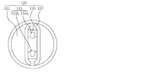
以下、本発明の実施例を添付図面を参照して詳しく説明する。図1は、本発明の一実施例による発光ダイオード照明灯の斜視図であり、図2は、本発明の一実施例による発光ダイオード照明灯の正面図である。図3は、本発明の一実施例による発光ダイオード照明灯の平面図であり、図4は、図3のIV−IV線断面図である。また、図5は、本発明の一実施例による発光ダイオード照明灯の側面図であり、図6は、図3のVI−VI線断面図である。 Hereinafter, embodiments of the present invention will be described in detail with reference to the accompanying drawings. FIG. 1 is a perspective view of a light-emitting diode illuminating lamp according to an embodiment of the present invention, and FIG. 2 is a front view of the light-emitting diode illuminating lamp according to an embodiment of the present invention. FIG. 3 is a plan view of a light-emitting diode illuminating lamp according to an embodiment of the present invention, and FIG. 4 is a cross-sectional view taken along line IV-IV in FIG. FIG. 5 is a side view of a light-emitting diode illuminating lamp according to an embodiment of the present invention, and FIG. 6 is a cross-sectional view taken along line VI-VI in FIG.
図1乃至図6を参照すれば、本発明の一実施例による発光ダイオード照明灯100は、一つ以上の発光ダイオード印刷回路基板(PCB)113と一つ以上の発光ダイオード印刷回路基板113の上面に配置される複数の発光ダイオード素子111とを含む発光ダイオードモジュール110、そして発光ダイオードモジュール110を囲むカバー120を含む。一方、発光ダイオード照明灯100は、カバー120の両端にそれぞれ結合される一対のベース130を含むことができる。ベース130のそれぞれは、カバー120の一端を覆う蓋131、電気を発光ダイオードモジュール110に供給するピン部133、ピン部133が固定されるようにピン部133の下側を囲む固定部135、そしてピン部133の上端よりも高く形成されてピン部133を周り方向に囲むガード部137を含む。一つ以上の発光ダイオード印刷回路基板113は、前方に放射される光の根源である複数の発光ダイオード素子111を固定させ、電気的に連結する役割を果たす。また、ピン部133を固定させる固定部135は、プラスチック射出物からなることができる。
1 to 6, a light
図4を参照すれば、ピン部133は、棒形状に並んで配置される二つのピン133a、133bを含み、二つのピン133a、133bは、外部の電源ソケットと結合するように蓋131の垂直方向外側に延長すると同時に、発光ダイオードモジュール110と連結されるように蓋131をそれぞれ貫通してカバー120内側に延長し得る。つまり、ピン133a、133bを通じて電源ソケットから発光ダイオードモジュール110に電源が供給される。図3および図4を参照すれば、ガード部137は、ピン部133の長さ(高さ)よりも長く(高く)形成され、ピン部133が使用者の手などに簡単に接触しないようにする役割を果たすことができる。
Referring to FIG. 4, the
また、一対のベース130は、R17Dベース規格であることができる。つまり、前述したベース130の形態は、R17Dベース規格に従う形態になることができる。本発明によれば、R17Dベース規格形態のベース130を使用することによって、電極であるピン部133が外部に露出しないため、感電や火災の危険性を防止して安全性を確保することができ、従来のG13ベースの蛍光灯用安定器にG13ベースの発光ダイオード照明灯を連結した時に発生し得る製品の損傷、火災の危険性などを防止することができる。図4を参照すれば、発光ダイオードモジュール110は、電気を交流電流(AC)の形態から直流電流(DC)の形態に変換して発光ダイオード印刷回路基板113に伝達するコンバータ部115をさらに含むことができる。図4に示されているように、コンバータ部115は、発光ダイオード印刷回路基板113の両端上面に配置され得、外部から供給されるAC(alternating current)110〜220Vの電源をDC(direct current)に変換する変換部である。
Further, the pair of
また、図4および図6を参照すれば、本発明の一実施例による発光ダイオード照明灯100は、一つ以上の発光ダイオード印刷回路基板(PCB)113と一つ以上の発光ダイオード印刷回路基板113の上面に配置される複数の発光ダイオード素子111とを含む発光ダイオードモジュール110、そして発光ダイオードモジュール110を囲むカバー120を含み、一つ以上の発光ダイオード印刷回路基板113は棒形状を有し、複数の発光ダイオード素子111は棒形状の長さ方向に沿って一列に配列されるように発光ダイオード印刷回路基板113の上面に配置される。また、図4および図6を参照すれば、カバー120は、複数の発光ダイオード素子111から放射される光が拡散するように複数の発光ダイオード素子111を囲む拡散カバー121、そして発光ダイオード印刷回路基板113の熱が分散するように発光ダイオード印刷回路基板113の下面を囲む放熱板123を含むことができる。
4 and 6, the light
例として図2および図6を参照すれば、拡散カバー121は、半円形の断面を有し、図2で見た時、左右方向に長く延長する、下側が開放された管形態をなし、複数の発光ダイオード素子111を囲むことができる。また、放熱板123は半円形の断面を有し、図2で見た時、左右方向に長く延長する、上側が開放された管形態をなし、一つ以上の発光ダイオード印刷回路基板113の下面を囲むことができる。また、図6に示されているように、拡散カバー121と放熱板123は互いに締結されて中空の円筒形態を有するように形成され得る。
Referring to FIGS. 2 and 6 as an example, the
次に、一つ以上の発光ダイオード印刷回路基板113が拡散カバー121と放熱板123の間に配置されて拡散カバー121または放熱板123と結合される方式について説明する。図6を参照すれば、放熱板123は、拡散カバー121と締結されるように中空の円筒形態の長さ方向に沿って両側面の外側にそれぞれ形成される外側溝123b、そして一つ以上の発光ダイオード印刷回路基板113と締結されるように前記中空の円筒形態の長さ方向に沿って両側面の内側にそれぞれ形成される内側溝123aを含むことができる。つまり、放熱板123の外側溝123bに半円形である拡散カバー121の下部が挿入される形態で結合され得る。また、放熱板123の内側溝123aに一つ以上の発光ダイオード印刷回路基板113の一部が挿入され得る。例として、一つ以上の発光ダイオード印刷回路基板113は一つで構成され、放熱板123に形成された両内側溝123aに棒形状の発光ダイオード印刷回路基板113の両側面がそれぞれ挿入され得る。他の例として、一つ以上の発光ダイオード印刷回路基板113が二つで構成され、放熱板123に形成された両内側溝123aに二つの棒形状の発光ダイオード印刷回路基板113の側面がそれぞれ挿入されることもできる。
Next, a method in which one or more light emitting diode printed
つまり、前述した結合方式は一実施例に過ぎないものであって、可能な多様な方式により一つ以上の発光ダイオード印刷回路基板113が拡散カバー121と放熱板123が形成する空間の内部に配置され得る。放熱板123の内側溝123aも一つ以上の発光ダイオード印刷回路基板113の構成に応じて安定的且つ効率的な結合のために多様に形成され得る。かかる拡散カバー121、放熱板123、そして一つ以上の発光ダイオード印刷回路基板113の結合方式は、拡散カバー121による光の放射効率と眩しさが低減する程度と、放熱板123による熱の放出効率を考慮して決めることが好ましい。これと同時に、発光ダイオードを利用した従来の照明装置は、カバーフレームの内側上面に発光ダイオードモジュールを付着し、カバーフレームの下側に全面的に拡散板を付着することによって、高価の拡散板が多量使用されて単価が高まり、LED光源と拡散板の距離が遠くなって放射効率が落ちる問題点があった。そこで本発明は、拡散カバー121と複数の発光ダイオード素子111との距離を最少化し、拡散カバー121を最小限に使用することによって、光が高効率に放射されながらも、眩しさを減少させることができ、単価を大幅に下げ、重量を減少させることができる効果もある。
That is, the above-described coupling method is only an example, and one or more light emitting diode printed
放熱板123と一つ以上の発光ダイオード印刷回路基板113の下面との間には空気層210が形成され得る。また、拡散カバー121と一つ以上の発光ダイオード印刷回路基板113の上面との間にも空気層220が形成され得る。かかる空気層210、220は熱による一つ以上の発光ダイオード印刷回路基板113の曲げを防止するために形成され得る。拡散カバー121は、発光ダイオード素子111からの光を前方に均一に拡散させるための材質とすることが好ましく、そのために、拡散カバー121は、拡散型ポリカーボネートまたは拡散型ガラス材質であることができる。放熱板123は、アルミニウム材質(AL放熱板)であることができる。アルミニウム材質を通じて熱が効果的に放出されながら重量も顕著に減少され得る。時間の経過と共に固定部などが自重で変形し、装置の一部が落下するなどの事故を、かかる重量の減少を通じて防止し得る効果もある。また、放熱板123は、ABS、PPS、そしてPPA材質で二重射出され得る。つまり、拡散カバー121との結合を通じて、放熱板123は拡散カバー121の曲げ剛性を高めることができるが、かかる放熱板123は、拡散カバー121と異なる材質であるABS(Acrvlonitrile/Butadien/Styrene)、PPS(Poly Phenylene Sulfide)、そしてPPA(Poly Phthal Amide)材質で二重射出され得る。ここで二重射出とは、複数の材料を混合して製品を製作することを意味する。かかる二重射出を通じて耐熱性などが強化され得る。かかる放熱板123は熱が効果的に放出され得る。
An
一方、図7は、本発明の他の実施例による発光ダイオード照明灯の断面図である。図7を参照すれば、本発明の他の実施例による発光ダイオード照明灯100によれば、放熱板123は、拡散カバー121と締結されるように中空の円筒形態の長さ方向に沿って両側面の外側にそれぞれ形成される外側溝123b、そして一つ以上の発光ダイオード印刷回路基板113が配置されるように中空の円筒形態の内部に中空の円筒形態の長さ方向に沿って形成される突出部123cを含むことができる。より詳しくは、図7に示されているように、突出部123cは、上面が二つに区画されるように断面がキャレット(caret)記号「^」形状であり、一つ以上の発光ダイオード印刷回路基板113は、突出部123cの区画された二つの上面にそれぞれ配置され得る。また、突出部123cは、一定の角度に折り、三つ以上に区画される断面形状を有するように構成されることもでき、三つ以上の発光ダイオード印刷回路基板113がその上面に配置され得る。このように複数の発光ダイオード素子を多様な角度に配置させることによって、光の放射角を広げることができる。
FIG. 7 is a cross-sectional view of a light-emitting diode illuminating lamp according to another embodiment of the present invention. Referring to FIG. 7, according to the
また、かかる放熱板123と突出部123cの下面との間には空気層210が形成され得る。また、拡散カバー121と一つ以上の発光ダイオード印刷回路基板113の上面との間にも空気層220が形成され得る。かかる空気層210、220は、熱による一つ以上の発光ダイオード印刷回路基板113の曲げを防止するために形成され得る。拡散カバー121は、発光ダイオード素子111からの光を前方に均一に拡散させるための材質とすることが好ましく、そのために、拡散カバー121は、拡散型ポリカーボネートまたは拡散型ガラス材質であることができる。また、放熱板123は、ABS、PPS、そしてPPA材質で二重射出され得る。つまり、拡散カバー121との結合を通じて、放熱板123は拡散カバー121の曲げ剛性を高めることができるが、かかる放熱板123は、拡散カバー121と異なる材質であるABS(Acrvlonitrile/Butadien/Styrene)、PPS(Poly Phenylene Sulfide)、そしてPPA(Poly Phthal Amide)材質で二重射出され得る。ここで二重射出とは、複数の材料を混合して製品を製作することを意味する。かかる二重射出を通じて耐熱性などが強化され得る。かかる放熱板123は熱が効果的に放出され得る。
An
一方、図8は、本発明のさらに他の実施例による発光ダイオード照明灯の断面図である。図8に示されているように、本発明のさらに他の実施例による発光ダイオード照明灯100によれば、カバー120は、複数の発光ダイオード素子111から放射される光が拡散するよう発光ダイオード印刷回路基板113を囲む中空の円筒形態である拡散カバー121を含むことができる。拡散カバー121と放熱板123が結合して円筒形態とすることで、複数の発光ダイオード素子111が上面に付着された一つ以上の発光ダイオード印刷回路基板113を囲むことができるが、拡散カバー121が円筒形態である場合には放熱板123の構成が除外され得る。つまり、円筒形態の拡散カバー121のみで発光ダイオード素子111が上面に付着された一つ以上の発光ダイオード印刷回路基板113を囲むことができる。例としては、円筒形のガラスチューブや円筒形の拡散チューブ内部に、一つ以上の発光ダイオード印刷回路基板113が挿入される形態で構成され得る。
FIG. 8 is a cross-sectional view of a light emitting diode illuminating lamp according to still another embodiment of the present invention. As shown in FIG. 8, according to the light emitting
拡散カバー121は、中空の円筒形態の長さ方向に沿って両側面の内側にそれぞれ形成される内側溝121aを含み、該内側溝121aが一つ以上の発光ダイオード印刷回路基板113と締結するようにしてもよい。このように円形の拡散型カバーを使用することによって、装置の重量を減少させて落下による破損または事故を防止することができる。拡散カバー121は、発光ダイオード素子111からの光を前方に均一に拡散させるための材質とすることが好ましく、そのために、拡散カバー121は、拡散型ポリカーボネートまたは拡散型ガラス材質であることができる。
The
以上で本発明の実施例を説明したが、本発明の権利範囲はこれに限定されず、本発明の実施例から本発明が属する技術分野で通常の知識を有する者により容易に変更されて均等なものと認められる範囲のすべての変更および修正を含む。 Although the embodiments of the present invention have been described above, the scope of rights of the present invention is not limited to this, and can be easily changed from those of the embodiments of the present invention to those having ordinary knowledge in the technical field to which the present invention belongs. Including all changes and modifications to the extent deemed acceptable.
本発明は、発光ダイオード照明灯に関するものであって、多様な種類の発光ダイオード照明灯に適用され得、産業上の利用可能性がある。 The present invention relates to a light-emitting diode illuminating lamp, which can be applied to various types of light-emitting diode illuminating lamps and has industrial applicability.
100…発光ダイオード照明灯
110…発光ダイオードモジュール
111…発光ダイオード素子
113…発光ダイオード印刷回路基板
115…コンバータ
120…カバー
121…拡散カバー
123…放熱板
130…ベース
131…蓋
133…ピン部
133a、133b…ピン
135…固定部
137…ガード部
210、220…空気層
121a、123a…内側溝
123b…外側溝
123c…突出部
DESCRIPTION OF
Claims (16)
前記発光ダイオードモジュールを囲むカバー、そして
前記カバーの両端にそれぞれ結合される一対のベースを含み、
前記ベースのそれぞれは、
前記カバーの一端を覆う蓋、
電気を前記発光ダイオードモジュールに供給するピン部、
前記ピン部が固定されるように前記ピン部の下側を囲む固定部、そして
前記ピン部の上端よりも高く形成されて前記ピン部を周り方向に囲むガード部を含む、発光ダイオード照明灯。 A light emitting diode module comprising one or more light emitting diode printed circuit boards and a plurality of light emitting diode elements disposed on an upper surface of the one or more light emitting diode printed circuit boards;
A cover surrounding the light emitting diode module; and a pair of bases respectively coupled to both ends of the cover;
Each of the bases is
A lid covering one end of the cover;
A pin portion for supplying electricity to the light emitting diode module;
A light-emitting diode illuminating lamp comprising: a fixing portion that surrounds a lower side of the pin portion so that the pin portion is fixed; and a guard portion that is formed higher than an upper end of the pin portion and surrounds the pin portion in a circumferential direction.
前記二つのピンは、前記蓋の垂直方向外側に延長すると同時に、前記発光ダイオードモジュールと連結されるように前記蓋をそれぞれ貫通して前記カバー内側に延長する、請求項1に記載の発光ダイオード照明灯。 The pin portion includes two pins arranged in a bar shape,
2. The light emitting diode illumination according to claim 1, wherein the two pins extend outward in the vertical direction of the lid and simultaneously extend through the lid and connect to the inside of the cover so as to be connected to the light emitting diode module. light.
前記複数の発光ダイオード素子は、前記棒形状の長さ方向に沿って一列に配列されるように前記一つ以上の発光ダイオード印刷回路基板の上面に配置される、請求項1に記載の発光ダイオード照明灯。 The one or more light emitting diode printed circuit boards have a bar shape;
2. The light emitting diode according to claim 1, wherein the plurality of light emitting diode elements are disposed on an upper surface of the one or more light emitting diode printed circuit boards so as to be arranged in a line along the length direction of the bar shape. Lighting light.
前記複数の発光ダイオード素子から放射される光が拡散するように前記複数の発光ダイオード素子を囲む拡散カバー、そして
前記一つ以上の発光ダイオード印刷回路基板の熱が分散するように前記一つ以上の発光ダイオード印刷回路基板の下面を囲む放熱板を含む、請求項5に記載の発光ダイオード照明灯。 The cover is
A diffusion cover surrounding the plurality of light emitting diode elements to diffuse light emitted from the plurality of light emitting diode elements; and the one or more light emitting diode printed circuit boards to disperse heat. The light-emitting diode illuminating lamp according to claim 5, further comprising a heat sink surrounding the lower surface of the light-emitting diode printed circuit board.
前記拡散カバーと締結されるように前記中空の円筒形態の長さ方向に沿って両側面の外側にそれぞれ形成される外側溝、そして
前記一つ以上の発光ダイオード印刷回路基板と締結されるように前記中空の円筒形態の長さ方向に沿って両側面の内側にそれぞれ形成される内側溝を含む、請求項10に記載の発光ダイオード照明灯。 The heat sink is
Outer grooves formed on the outer sides of both sides along the length of the hollow cylindrical shape to be fastened to the diffusion cover, and fastened to the one or more light emitting diode printed circuit boards. The light-emitting diode illuminating lamp according to claim 10, further comprising an inner groove formed inside each side surface along the length direction of the hollow cylindrical shape.
前記拡散カバーと締結されるように前記中空の円筒形態の長さ方向に沿って両側面の外側にそれぞれ形成される外側溝、そして
前記一つ以上の発光ダイオード印刷回路基板が配置されるように前記中空の円筒形態の内部に前記中空の円筒形態の長さ方向に沿って形成される突出部を含む、請求項10に記載の発光ダイオード照明灯。 The heat sink is
Outer grooves formed on the outer sides of both sides along the length direction of the hollow cylindrical shape to be fastened to the diffusion cover, and the one or more light emitting diode printed circuit boards are disposed. The light-emitting diode illuminating lamp according to claim 10, further comprising a protrusion formed along a length direction of the hollow cylindrical shape inside the hollow cylindrical shape.
前記一つ以上の発光ダイオード印刷回路基板は、二つで構成されて前記突出部の区画された二つの上面にそれぞれ配置される、請求項12に記載の発光ダイオード照明灯。 The protrusion has a caret symbol “^” shape in cross section so that the upper surface is partitioned into two parts.
The light emitting diode illuminating lamp of claim 12, wherein the one or more light emitting diode printed circuit boards are formed of two and disposed on two upper surfaces defined by the protrusions.
Applications Claiming Priority (3)
| Application Number | Priority Date | Filing Date | Title |
|---|---|---|---|
| KR1020100030174A KR100997646B1 (en) | 2010-04-02 | 2010-04-02 | Led lighting lamp |
| KR10-2010-0030174 | 2010-04-02 | ||
| PCT/KR2011/001980 WO2011122781A2 (en) | 2010-04-02 | 2011-03-23 | Light emitting diode lighting lamp |
Publications (1)
| Publication Number | Publication Date |
|---|---|
| JP2013502036A true JP2013502036A (en) | 2013-01-17 |
Family
ID=43512236
Family Applications (1)
| Application Number | Title | Priority Date | Filing Date |
|---|---|---|---|
| JP2012524666A Pending JP2013502036A (en) | 2010-04-02 | 2011-03-23 | Light-emitting diode lamp |
Country Status (6)
| Country | Link |
|---|---|
| US (1) | US8757832B2 (en) |
| EP (1) | EP2434213A4 (en) |
| JP (1) | JP2013502036A (en) |
| KR (1) | KR100997646B1 (en) |
| CN (1) | CN102472476B (en) |
| WO (1) | WO2011122781A2 (en) |
Cited By (1)
| Publication number | Priority date | Publication date | Assignee | Title |
|---|---|---|---|---|
| JP5540157B2 (en) * | 2012-03-09 | 2014-07-02 | パナソニック株式会社 | Lamp and lighting device |
Families Citing this family (32)
| Publication number | Priority date | Publication date | Assignee | Title |
|---|---|---|---|---|
| US11480306B2 (en) | 2008-09-05 | 2022-10-25 | Jiaxing Super Lighting Electric Appliance Co., Ltd. | LED tube lamp |
| US11131431B2 (en) | 2014-09-28 | 2021-09-28 | Jiaxing Super Lighting Electric Appliance Co., Ltd | LED tube lamp |
| JP2014035826A (en) * | 2012-08-07 | 2014-02-24 | Toshiba Lighting & Technology Corp | Light source apparatus and lighting apparatus |
| JP6171796B2 (en) * | 2012-10-03 | 2017-08-02 | 日亜化学工業株式会社 | Light emitting device |
| DE102013202282A1 (en) * | 2013-02-13 | 2014-08-14 | Continental Automotive Gmbh | Light source and method for producing the light source |
| KR101265235B1 (en) | 2013-02-25 | 2013-05-16 | 주식회사 경우 | Led lamp |
| CN104033748B (en) * | 2013-03-07 | 2018-05-25 | 欧司朗有限公司 | Lighting device |
| US20140301068A1 (en) * | 2013-04-09 | 2014-10-09 | Tong Hong Investment Co., Ltd. | Easily assembled led tube lamp structure |
| JP2015050191A (en) * | 2013-09-04 | 2015-03-16 | ルミリッチ シーオー エルティディ | Light emitting diode lamp using alternating current voltage |
| CN203549453U (en) * | 2013-09-26 | 2014-04-16 | 东莞市赛钢装饰材料有限公司 | Tube-in-tube LED lamp |
| TW201520473A (en) * | 2013-11-22 | 2015-06-01 | Lextar Electronics Corp | Light tube structure |
| USD743587S1 (en) * | 2013-12-30 | 2015-11-17 | Kumho Electric, Inc. | LED fluorescent lamp |
| DE102014202759A1 (en) * | 2014-02-14 | 2015-08-20 | Osram Gmbh | Semiconductor tube lamp |
| KR20150117911A (en) * | 2014-04-11 | 2015-10-21 | 삼성전자주식회사 | Lighting device |
| US9074742B1 (en) | 2014-06-09 | 2015-07-07 | Richard J. Petrocy | Modularized display apparatus and method |
| US9202397B1 (en) | 2014-06-09 | 2015-12-01 | Richard J. Petrocy | Modularized lighting display system |
| US9519278B2 (en) | 2014-06-09 | 2016-12-13 | Richard J. Petrocy | Modularized self-addressing apparatus and method |
| US11480305B2 (en) | 2014-09-25 | 2022-10-25 | Jiaxing Super Lighting Electric Appliance Co., Ltd. | LED tube lamp |
| CN205213093U (en) | 2014-09-28 | 2016-05-04 | 嘉兴山蒲照明电器有限公司 | Rectification filter circuit , lamp and LED straight tube lamp |
| US10560989B2 (en) | 2014-09-28 | 2020-02-11 | Jiaxing Super Lighting Electric Appliance Co., Ltd | LED tube lamp |
| US9989200B2 (en) * | 2014-10-20 | 2018-06-05 | Argo Import-Export Ltd. | LED lighting tube device and method |
| WO2016064789A1 (en) * | 2014-10-20 | 2016-04-28 | Argo Import-Export, Ltd | Led lighting tube device and method |
| US10514134B2 (en) | 2014-12-05 | 2019-12-24 | Jiaxing Super Lighting Electric Appliance Co., Ltd | LED tube lamp |
| US9897265B2 (en) | 2015-03-10 | 2018-02-20 | Jiaxing Super Lighting Electric Appliance Co., Ltd. | LED tube lamp having LED light strip |
| EP3356733B1 (en) * | 2015-09-29 | 2021-11-10 | Corvi Led PVT Ltd | Led tubular lamp assembly |
| DE202016104177U1 (en) * | 2016-07-29 | 2017-11-02 | Rehau Ag + Co | lighting device |
| AU2018321981B2 (en) | 2017-08-25 | 2022-02-03 | Agnetix, Inc. | Fluid-cooled LED-based lighting methods and apparatus for controlled environment agriculture |
| US10999976B2 (en) | 2017-09-19 | 2021-05-11 | Agnetix, Inc. | Fluid-cooled lighting systems and kits for controlled agricultural environments, and methods for installing same |
| CN113163720A (en) | 2018-11-13 | 2021-07-23 | 阿格尼泰克斯股份有限公司 | Fluid cooled LED-based lighting method and apparatus for controlled environment agriculture with integrated camera and/or sensor and wireless communication |
| AU2020402051A1 (en) | 2019-12-10 | 2022-08-04 | Agnetix, Inc. | Multisensory imaging methods and apparatus for controlled environment horticulture using irradiators and cameras and/or sensors |
| WO2021119587A1 (en) * | 2019-12-12 | 2021-06-17 | Agnetix, Inc. | Fluid-cooled led-based lighting fixture in close proximity grow systems for controlled environment horticulture |
| FR3107944B1 (en) * | 2020-03-05 | 2022-02-11 | Bordes Jacques | LED system without heat sink |
Citations (8)
| Publication number | Priority date | Publication date | Assignee | Title |
|---|---|---|---|---|
| JP2000011738A (en) * | 1998-06-23 | 2000-01-14 | Toshiba Tec Corp | Lamp socket |
| JP2002140901A (en) * | 2000-10-31 | 2002-05-17 | Hitachi Building Systems Co Ltd | Led illuminating lamp and escalator provided with the same |
| JP2003263917A (en) * | 2002-03-08 | 2003-09-19 | Matsushita Electric Works Ltd | Luminaire |
| JP2008243498A (en) * | 2007-03-27 | 2008-10-09 | First System Co Ltd | Led lighting device |
| JP3148527U (en) * | 2008-11-10 | 2009-02-19 | 珍通能源技術股▲ふん▼有限公司 | Light-emitting diode lamp tube with multistage adjustment of circuit board position |
| JP3148721U (en) * | 2008-12-11 | 2009-02-26 | 株式会社サンテック | LED lighting device |
| JP2010003683A (en) * | 2008-05-19 | 2010-01-07 | Katsukiyo Morii | Illumination lamp using light-emitting element |
| JP2010040221A (en) * | 2008-07-31 | 2010-02-18 | Toshiba Lighting & Technology Corp | Self-ballasted lamp |
Family Cites Families (27)
| Publication number | Priority date | Publication date | Assignee | Title |
|---|---|---|---|---|
| JP2740302B2 (en) | 1989-11-01 | 1998-04-15 | 鐘紡株式会社 | Electric carpet and its surface material |
| JPH03148721A (en) | 1989-11-06 | 1991-06-25 | Omron Corp | Digitizer |
| JP4153870B2 (en) * | 2001-07-02 | 2008-09-24 | 森山産業株式会社 | Display / lighting device and display / lighting system |
| EP1794808B1 (en) * | 2004-09-10 | 2017-08-09 | Seoul Semiconductor Co., Ltd. | Light emitting diode package having multiple molding resins |
| US7052171B1 (en) * | 2004-12-15 | 2006-05-30 | Emteq, Inc. | Lighting assembly with swivel end connectors |
| US8115411B2 (en) * | 2006-02-09 | 2012-02-14 | Led Smart, Inc. | LED lighting system |
| US8235539B2 (en) * | 2006-06-30 | 2012-08-07 | Electraled, Inc. | Elongated LED lighting fixture |
| CN201041307Y (en) * | 2007-04-30 | 2008-03-26 | 蔡焯桂 | Daylight lamp fixture |
| KR200444408Y1 (en) * | 2007-06-14 | 2009-05-12 | 아림산업 주식회사 | Connector terminal for fluorescent lamp |
| CN101113809A (en) * | 2007-07-16 | 2008-01-30 | 伍拓山 | Canula type sun lamp |
| CN201083365Y (en) * | 2007-09-29 | 2008-07-09 | 蔡晓宇 | LED lamp capable of combining |
| CN101235959B (en) * | 2008-02-02 | 2011-10-05 | 中微光电子(潍坊)有限公司 | LED illuminating source |
| CN201173443Y (en) * | 2008-03-23 | 2008-12-31 | 九泰光电科技有限公司 | Electricity-saving type daylight lamp tube and daylight lamp tube conversion base group |
| JP3142652U (en) | 2008-04-10 | 2008-06-19 | 大阪府 | Both-ends terminal structure of straight tube LED fluorescent lamp |
| US8360599B2 (en) * | 2008-05-23 | 2013-01-29 | Ilumisys, Inc. | Electric shock resistant L.E.D. based light |
| CN201259191Y (en) * | 2008-06-13 | 2009-06-17 | 深圳高光电子有限公司 | Heat radiation reinforced LED illuminating apparatus |
| CN201269416Y (en) * | 2008-08-06 | 2009-07-08 | 东莞市大雁电子科技有限公司 | LED daylight lamp tube |
| CN201273479Y (en) * | 2008-09-26 | 2009-07-15 | 华能光电科技股份有限公司 | Customized combination type luminous module used for generating vertical electric connection |
| US7896701B2 (en) * | 2008-11-04 | 2011-03-01 | Everlight Electronics Co., Ltd. | Connector and light source apparatus |
| CN201297526Y (en) * | 2008-11-07 | 2009-08-26 | 舟山浩德光电科技有限公司 | LED strip lamp |
| US8382321B2 (en) * | 2008-11-11 | 2013-02-26 | Dongbu Hitek Co., Ltd. | Illumination apparatus having an adapter with a function block slot |
| US8232724B2 (en) * | 2009-02-06 | 2012-07-31 | Tyco Electronics Corporation | End cap assembly for a light tube |
| CN201331029Y (en) * | 2009-02-09 | 2009-10-21 | 东莞凤岗五联励国灯饰制造厂 | LED florescent lamp |
| KR100918995B1 (en) | 2009-04-01 | 2009-09-25 | (주)세미백아이엔씨 | A led lighting device |
| CN101576208A (en) * | 2009-06-03 | 2009-11-11 | 深圳万润科技股份有限公司 | LED (Light Emitting Diode) fluorescent lamp |
| KR100938932B1 (en) * | 2009-07-09 | 2010-01-27 | 김종성 | A reflecting shade with anti-dust radiator and corner cube for led lamp and the manufacturing methods thereof |
| KR100949699B1 (en) * | 2009-12-04 | 2010-03-29 | 엔 하이테크 주식회사 | Fluorescent lamp of led |
-
2010
- 2010-04-02 KR KR1020100030174A patent/KR100997646B1/en not_active IP Right Cessation
-
2011
- 2011-03-23 WO PCT/KR2011/001980 patent/WO2011122781A2/en active Application Filing
- 2011-03-23 EP EP11762953.5A patent/EP2434213A4/en not_active Withdrawn
- 2011-03-23 JP JP2012524666A patent/JP2013502036A/en active Pending
- 2011-03-23 US US13/379,647 patent/US8757832B2/en not_active Expired - Fee Related
- 2011-03-23 CN CN201180002625.6A patent/CN102472476B/en not_active Expired - Fee Related
Patent Citations (8)
| Publication number | Priority date | Publication date | Assignee | Title |
|---|---|---|---|---|
| JP2000011738A (en) * | 1998-06-23 | 2000-01-14 | Toshiba Tec Corp | Lamp socket |
| JP2002140901A (en) * | 2000-10-31 | 2002-05-17 | Hitachi Building Systems Co Ltd | Led illuminating lamp and escalator provided with the same |
| JP2003263917A (en) * | 2002-03-08 | 2003-09-19 | Matsushita Electric Works Ltd | Luminaire |
| JP2008243498A (en) * | 2007-03-27 | 2008-10-09 | First System Co Ltd | Led lighting device |
| JP2010003683A (en) * | 2008-05-19 | 2010-01-07 | Katsukiyo Morii | Illumination lamp using light-emitting element |
| JP2010040221A (en) * | 2008-07-31 | 2010-02-18 | Toshiba Lighting & Technology Corp | Self-ballasted lamp |
| JP3148527U (en) * | 2008-11-10 | 2009-02-19 | 珍通能源技術股▲ふん▼有限公司 | Light-emitting diode lamp tube with multistage adjustment of circuit board position |
| JP3148721U (en) * | 2008-12-11 | 2009-02-26 | 株式会社サンテック | LED lighting device |
Cited By (1)
| Publication number | Priority date | Publication date | Assignee | Title |
|---|---|---|---|---|
| JP5540157B2 (en) * | 2012-03-09 | 2014-07-02 | パナソニック株式会社 | Lamp and lighting device |
Also Published As
| Publication number | Publication date |
|---|---|
| CN102472476A (en) | 2012-05-23 |
| WO2011122781A2 (en) | 2011-10-06 |
| WO2011122781A3 (en) | 2012-01-05 |
| US20120099302A1 (en) | 2012-04-26 |
| KR100997646B1 (en) | 2010-12-01 |
| CN102472476B (en) | 2014-01-15 |
| US8757832B2 (en) | 2014-06-24 |
| EP2434213A2 (en) | 2012-03-28 |
| EP2434213A4 (en) | 2015-03-04 |
Similar Documents
| Publication | Publication Date | Title |
|---|---|---|
| JP2013502036A (en) | Light-emitting diode lamp | |
| JP5736151B2 (en) | Lighting device | |
| EP2151620A1 (en) | Light emitting diode (LED) light tube | |
| JP2010511971A (en) | LED lighting for fluorescent lamps with ballast | |
| JP2011100736A (en) | Lighting device | |
| JP2002141555A (en) | Led illumination lamp and method for manufacturing led illumination lamp | |
| JP2009218209A (en) | Assembly type led illumination apparatus | |
| KR101021722B1 (en) | Illuminator | |
| KR101093073B1 (en) | LED illumination Lamp | |
| KR100982450B1 (en) | Led illumination lamp | |
| KR101427121B1 (en) | Lighting fixture using lighting emitting diode | |
| KR101319991B1 (en) | Waterproof structure for led lamp | |
| TWM452292U (en) | LED vertical lamp | |
| JP3163443U (en) | LED lighting device | |
| TWM399284U (en) | LED tube and led tube lamp | |
| KR101044985B1 (en) | Led fluorescent lamp | |
| KR101292217B1 (en) | Led illumination lamp | |
| KR101055767B1 (en) | Led illumination lamp | |
| TWM365434U (en) | Improved type light emitting diode (LED) daylight lamp | |
| KR102073567B1 (en) | Led lighting device compatible with fpl type fixtures | |
| KR101145167B1 (en) | Led fluorescent lamp | |
| KR20120076868A (en) | Straight type led lamp | |
| KR20110050913A (en) | Lighting device | |
| KR20110050912A (en) | Lighting device | |
| RU129191U1 (en) | CASE-FREE LED LAMP |
Legal Events
| Date | Code | Title | Description |
|---|---|---|---|
| A131 | Notification of reasons for refusal |
Free format text: JAPANESE INTERMEDIATE CODE: A131 Effective date: 20130416 |
|
| A601 | Written request for extension of time |
Free format text: JAPANESE INTERMEDIATE CODE: A601 Effective date: 20130712 |
|
| A602 | Written permission of extension of time |
Free format text: JAPANESE INTERMEDIATE CODE: A602 Effective date: 20130722 |
|
| A521 | Request for written amendment filed |
Free format text: JAPANESE INTERMEDIATE CODE: A523 Effective date: 20130807 |
|
| A02 | Decision of refusal |
Free format text: JAPANESE INTERMEDIATE CODE: A02 Effective date: 20131105 |