JP2013247227A - Method for removing cover of storing container - Google Patents
Method for removing cover of storing container Download PDFInfo
- Publication number
- JP2013247227A JP2013247227A JP2012119760A JP2012119760A JP2013247227A JP 2013247227 A JP2013247227 A JP 2013247227A JP 2012119760 A JP2012119760 A JP 2012119760A JP 2012119760 A JP2012119760 A JP 2012119760A JP 2013247227 A JP2013247227 A JP 2013247227A
- Authority
- JP
- Japan
- Prior art keywords
- lid
- space
- port door
- door
- gap space
- Prior art date
- Legal status (The legal status is an assumption and is not a legal conclusion. Google has not performed a legal analysis and makes no representation as to the accuracy of the status listed.)
- Granted
Links
Images

Abstract
Description
本発明は、半導体等の製造工程において使用される所謂フォトマスク等を保管、搬送等する際に用いられるSMIFポッドに例示される、被収容物を収容する収容容器に関し、より詳細には該収容容器の蓋の開閉操作に関し、特に蓋の取り外し方法に関するものである。 The present invention relates to a storage container for storing an object to be stored, exemplified by a SMIF pod used when storing and transporting a so-called photomask used in a manufacturing process of a semiconductor or the like, and more specifically, the storage. More particularly, the present invention relates to a method of removing the lid.
例えば半導体製造プロセスでは、ウエハ上に回路パターンを形成する際にリソグラフ用のフォトマスクを用い、当該フォトマスクに形成されている回路パターンを該ウエハ上に転写する工程が行われる。このようなフォトマスクは、通常は単体にて専用の容器に収容され、使用時まで保管される。当該容器はその開閉の形態より、SMIF(Standard Mechanical Interface)に対応するSMIFポッドと称呼される。例えば特許文献1には、フォトマスクを収容可能な収容空間を有し且つ該収容空間が下方に開口する本体部と、該開口を本体部下方より閉鎖すると共に実質的にフォトマスクを支持、固定する底蓋とからなるSMIFポッドが開示されている。該SMIFポッドは、内部において圧力変化が生じた場合であっても本体部に対して底蓋(以下蓋と称する。)を安定的に固定することにより、その内部に保管されるフォトマスクを清浄な状態に維持可能としている。 For example, in a semiconductor manufacturing process, a lithographic photomask is used when forming a circuit pattern on a wafer, and a step of transferring the circuit pattern formed on the photomask onto the wafer is performed. Such a photomask is usually stored alone in a dedicated container and stored until use. The container is referred to as an SMIF pod corresponding to SMIF (Standard Mechanical Interface) because of its open / closed form. For example, in Patent Document 1, there is a housing portion that can accommodate a photomask, and the housing space opens downward, and the opening is closed from below the body portion and substantially supports and fixes the photomask. A SMIF pod comprising a bottom lid is disclosed. The SMIF pod cleans the photomask stored in its interior by stably fixing the bottom lid (hereinafter referred to as lid) to the main body even when pressure changes occur inside. It can be maintained in a stable state.
フォトマスク使用時においては、専用のオープナーによって該ポッドの蓋の開閉とフォトマスクの取出しとが行われる。該オープナーは、内部空間、ポートドア、ドア駆動機構、ラッチ駆動機構、及び搬送用ロボットを有する。該内部空間は、付随する排気機構によって真空排気可能とされる。ポートドアは、該内部空間上部に設けられた第一の開口部を閉鎖可能であり、該内部空間を閉鎖した状態において該内部空間の天井の一部を構成すると共に、その上面に容器を載置及び固定が可能となるように構成されている。ドア駆動機構は、該ポートドアを上下動させて、ポッドの蓋及び該蓋上に支持されたフォトマスクを内部空間内に引き込む操作を行う。ラッチ駆動機構は、該ポッドの本体部に蓋を固定するために蓋に配されたラッチ機構を操作して、本体部に対する蓋の固定、開放を行う。搬送用ロボットは該内部空間とは異なる搬送用の空間に配置され、ドア駆動機構の操作によって内部空間内に収容された蓋に支持されたフォトマスクを実際に取り出し、実際にフォトマスクを搭載する装置に向けて第一の開口部とは異なる第二の開口部を介して搬送する。 When the photomask is used, the pod lid is opened and closed and the photomask is taken out by a dedicated opener. The opener has an internal space, a port door, a door drive mechanism, a latch drive mechanism, and a transfer robot. The internal space can be evacuated by an accompanying exhaust mechanism. The port door can close a first opening provided in the upper part of the internal space, and forms a part of the ceiling of the internal space in a state where the internal space is closed, and a container is mounted on the upper surface thereof. It is configured so that it can be placed and fixed. The door drive mechanism performs an operation of moving the port door up and down to draw the lid of the pod and the photomask supported on the lid into the internal space. The latch driving mechanism operates a latch mechanism disposed on the lid to fix the lid to the main body of the pod, thereby fixing and opening the lid with respect to the main body. The transfer robot is arranged in a transfer space different from the internal space, and actually takes out the photomask supported by the lid accommodated in the internal space by operating the door drive mechanism, and actually mounts the photomask. It is conveyed toward the apparatus through a second opening different from the first opening.
ここで、フォトマスクに微細な塵等が付着した場合、この塵はリソグラフ工程において回路パターンと共にウエハ上に転写されて配線不良の原因となる。そのため、このような塵には厳重な管理が為されており、前述した特許文献1に開示される構成等において、蓋の開閉時においても現状のデザインルールにおいては、許容される範囲に管理されている。しかし、半導体の高性能化に伴って配線幅、配線ピッチは今後より狭矮化することが見込まれており、これまで以上に塵を排除して更に清浄な環境を実現することが求められ始めている。 Here, when fine dust or the like adheres to the photomask, this dust is transferred onto the wafer together with the circuit pattern in the lithographic process, causing wiring defects. For this reason, strict management is performed on such dust, and in the configuration disclosed in Patent Document 1 described above, even when the lid is opened and closed, the current design rules are managed within an allowable range. ing. However, as the performance of semiconductors increases, the wiring width and wiring pitch are expected to become narrower in the future, and it is beginning to be required to realize a cleaner environment by removing dust more than ever. Yes.
本発明は以上の状況に鑑みて為されたものであり、フォトマスクに対する従来問題とならなかった微細な塵等の付着の抑制を可能とするフォトマスク等のための収容容器たる所謂SMIFポッドの蓋開閉方法、特に蓋の取り外し方法の提供を目的とする。 The present invention has been made in view of the above situation, and is a so-called SMIF pod that is a container for a photomask and the like that can suppress adhesion of fine dust or the like that has not been a problem with respect to a photomask. The object is to provide a lid opening / closing method, particularly a lid removing method.
上記課題を解決するために、本発明に係る蓋取り外し方法は、被収容物を支持する底蓋によって底部に設けられた開口が閉鎖される収容空間を有した収容容器より底蓋を取り外すオープナーであって、収容容器を上面に載置可能なポートドアと、ポートドアによって閉鎖される開口部を介して底蓋を収容可能な内部空間を構成するチャンバと、開口部を閉鎖したポートドアと蓋との間の間隙空間を排気可能な排気系と、ポートドアを内部空間内に降下させるドア駆動機構と、ポートドアに対して相対的に底蓋を昇降させる相対昇降手段と、を有するオープナーを用いて底蓋を取り外す工程であって、ポートドアの上面に収容容器を配置する工程と、底蓋とポートドアとの間に形成される間隙空間を排気系により排気する工程と、相対昇降手段により底蓋をポートドアに対して相対的に降下させて収容容器の収容空間と間隙空間とを連通させて収容空間と間隙空間との内部圧力を等しくする工程と、ドア駆動機構により底蓋と共にポートドアを内部空間内に降下させる工程と、を有することを特徴とする。 In order to solve the above problems, a lid removing method according to the present invention is an opener that removes a bottom lid from a housing container having a housing space in which an opening provided at the bottom is closed by a bottom lid that supports an object to be stored. A port door capable of placing the container on the upper surface, a chamber constituting an internal space capable of accommodating the bottom lid through an opening closed by the port door, and a port door and lid closed in the opening An opener having an exhaust system capable of exhausting the gap space between the door, a door drive mechanism for lowering the port door into the internal space, and a relative lifting means for lifting and lowering the bottom lid relative to the port door. A step of removing the bottom lid using the step of disposing a receiving container on the upper surface of the port door, a step of exhausting a gap space formed between the bottom lid and the port door by an exhaust system, and a relative lifting means A step of lowering the bottom cover relative to the port door to make the storage space of the storage container communicate with the gap space and equalize the internal pressure of the storage space and the gap space; together with the bottom cover by the door drive mechanism Lowering the port door into the interior space.
なお、上述した方法においては、相対昇降手段とドア駆動機構との動作タイミングを規定する降下タイミング決定機構を該オープナーが更に有し、収容空間と間隙空間との内部圧力を等しくする工程において降下タイミング決定機構が相対昇降手段の動作開始時刻からドア駆動機構の動作開始時刻までの間に時間遅れを設けることが好ましい。更に、前述した排気系は間隙空間を排気する工程及び収容空間と間隙空間との内部圧力を等しくする工程において間隙空間の排気を継続することがより好ましい。また、収容空間と間隙空間との内部圧力を等しくする工程では、相対昇降手段によるポートドアに対する底蓋の相対的な降下を一旦停止することとしても良い。更に、収容空間と間隙空間との内部圧力を等しくする工程では、ドア駆動機構によりポートドアの昇降が停止されていることとしても良い。 In the above-described method, the opener further includes a lowering timing determination mechanism that defines the operation timing of the relative lifting means and the door driving mechanism, and the lowering timing is determined in the step of equalizing the internal pressures of the housing space and the gap space. It is preferable that the determination mechanism provides a time delay between the operation start time of the relative lifting and lowering means and the operation start time of the door drive mechanism. Furthermore, it is more preferable that the exhaust system described above continues exhausting the gap space in the step of exhausting the gap space and the step of equalizing the internal pressures of the accommodating space and the gap space. Further, in the step of equalizing the internal pressures of the accommodation space and the gap space, the relative lowering of the bottom lid with respect to the port door by the relative lifting means may be temporarily stopped. Further, in the step of equalizing the internal pressures of the accommodating space and the gap space, the door drive mechanism may be stopped from raising and lowering the port door.
本発明によれば、今後問題視されるより微細に塵等に関しても、フォトマスク取出し時における該フォトマスクに対する付着を抑制し、より微細なデザインルールを満たす半導体装置を製造することが可能となる。 According to the present invention, it becomes possible to manufacture a semiconductor device satisfying a finer design rule by suppressing adhesion to a photomask when taking out the photomask, even with respect to finer dust, which will be a problem in the future. .
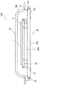
以下、図面を参照して本発明の一実施形態について説明する。図1は、本発明の一実施形態に係る蓋開閉方法に供せられるSMIFポッドの概略構成を厚さ方向の断面により示している。当該SMIFポッド100は、本体部10及び蓋(底蓋)20を有する。本体部10は、蓋20が支持するフォトマスク1を収容可能な大きさからなる収容空間10aと、該収容空間10aより下方に開口する開口10bと、後述するラッチピン29が嵌合するラッチ穴10cと、を有する。蓋20は、開口10bを下方から閉鎖する大きさを有する平板状の部材からなり、本体部10の開口10bを閉鎖した際に収容空間10a側に位置する表面20aの表面に位置決めピン21、支持ピン23、シール部材27を有する。また、蓋20は、下面20bからの操作によって平板形状の周面からのラッチピン29の突き出し或いは引込みの操作が可能な不図示のラッチ機構も有する。
Hereinafter, an embodiment of the present invention will be described with reference to the drawings. FIG. 1 shows a schematic configuration of a SMIF pod used in a lid opening / closing method according to an embodiment of the present invention by a section in a thickness direction. The
支持ピン23は蓋20の表面20aから垂直に突き出すように固定されており、上端部においてフォトマスク1を支持する。位置決めピン21は支持ピン23上の適正な位置にフォトマスク1が配置されるように、当該配置時におけるフォトマスク1の外周部の移動を制限するように表面20aに対して固定される。環状のシール部材27は蓋20の表面の外周に沿ってその内側に配置され、本体部10に設けられたシール面と当接して収容空間10aの密閉状態を担保する。ラッチピン29は蓋20が開口10bを閉鎖する際に本体部10に設けられるラッチ穴10cと対応する位置に配置され、蓋20の周面から突き出すことによって該ラッチ穴10c内に挿入されて、例えば搬送時等において蓋20が本体部10から落下することを防止する。なお、本実施形態では、フォトマスク1はトレイ3に載置されて、該トレイ3を介して支持ピン23上に支持されている。しかし、当該トレイ3をなくしてフォトマスク1を直接支持ピン23等で支持する構成とすることも可能である。
The
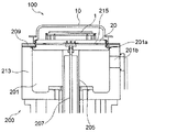
次に、本発明の一実施形態である蓋開閉方法を実際に行うオープナー200について述べる。図2(a)〜2(d)はオープナー200上に載置したSMIFポッド100についてこれらの断面構成を模式的に示し、蓋20の開放操作の進行段階に応じてこれらを図2(a)、2(b)、2(c)及び2(d)の順で各々示している。ここで、オープナー200は、内部空間201、ポートドア203、ドア駆動機構205、ラッチ駆動機構207、排気系209、及びチャンバ213を有する。チャンバ213は、内部空間201を構成する筐体様の部材であり、該内部空間201より連通して外部空間に開口し且つポートドア203により閉鎖される第一の開口部201aを有する。内部空間201は不図示のチャンバ用排気系(前述した排気機構)に接続されて所謂真空排気が可能であり、前述した上方に設けられた第一の開口部201a、及び側方に設けられた第二の開口部201bを有する。該内部空間201は蓋20を収容可能な大きさを有する。
Next, an
ポートドア203は第一の開口部201aを閉鎖すると共に、その上面にSMIFポッド100を載置可能とされている。ドア駆動機構205はポートドア203を下方から支持し、該ポートドア203を内部空間201の内部に引き込むように降下させ、或いは第一の開口部201aを閉鎖するように上昇させる。ラッチ駆動機構207はポートドア203上にSMIFポッド100を載置させた際に該SMIFポッド100の蓋20のラッチ機構と協働し、ラッチ穴10cに対するラッチピン29の挿入、退出の操作を行う。また、ラッチ駆動機構207は、ラッチ機構とは別な蓋20の被係合部とも係合可能であり、この係合状態を利用して該ラッチ駆動機構207によってポートドア203に対する相対的な蓋20の昇降を行うことも可能となっている。即ち、該ラッチ駆動機構207は、本発明において蓋20をポートドア203に対して相対的に昇降させる相対昇降手段としての機能も有する。SMIFポッド排気系209は、SMIFポッド100の蓋20の底面20bとこれが載置されるポートドア203の上面との間の空間である間隙空間215の排気が可能である。また、必要に応じて該SMIFポッド100の蓋20を降下させて該間隙空間215と収容空間10aとを連通させることにより収容空間10a内部の排気も可能とする。
The
より詳細には、ドア駆動機構205は、図2中の更に下方において不図示の第一昇降用アクチュエータに接続されている。この第一昇降用アクチュエータ等からなる実際の機構は特許文献1等に開示される公知機構より構築されたものであることから、以降において詳述は行わない。また、ラッチ駆動機構207は、同図中の更に下方において不図示の回動用モータ及び第二の昇降用アクチュエータに接続されている。回動用モータは、ラッチ駆動機構207の延在軸回りに上端部を回転させる。該上端部にはSMIFポッド100の蓋20のラッチ機構と係合する部材が配置されており、この回転動作によってラッチ機構との係合と該ラッチ機構の駆動とが為される。更に第二の昇降用アクチュエータは、ドア駆動機構205の第一昇降用アクチュエータとは独立して昇降動作を行うことが可能となっている。当該構成により、該ラッチ駆動機構207には相対昇降手段としての機能が付与される。なお、このような構成はドア駆動機構205と同様に特許文献1等に開示される公知機構より構築されたものであることから、以降において詳述は行わない。
More specifically, the
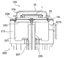
次に前述したオープナー200を用いたSMIFポッド100の蓋開放方法に関して、その工程を詳述する。まず図2(a)に示されるようにポートドア203上にSMIFポッド100を載置する。その際、ラッチ駆動機構207はSMIFポッド100の蓋20に設けられたラッチ機構(不図示)と係合し、該ラッチ駆動機構207によるラッチピン29の操作が可能な状態となる。また、この状態では、蓋20における大気側面である裏面20bと、ポートドア203と、の間の間隙空間215は大気圧の状態にある。続いて図2(b)に示すようにSMIFポッド排気系209等を介した蓋20とポートドア203との間の間隙空間215内の減圧が為される。当該間隙空間215内の圧力があるレベル以下となった後、ラッチ駆動機構207によりラッチピン29のラッチ穴10cからの退避操作が為される。該操作により蓋20を本体部10から分離可能となる。なお、間隙空間215の圧力に関しては、SMIFポッド排気系209に配した圧力測定器によって把握しても良く、排気時間に基づいて類推することとしても良い。
Next, the process of the method for opening the lid of the
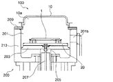
続いて該ラッチ駆動機構207は蓋20を微少量降下させ、開口10bを僅かに開放して間隙空間215とSMIFポッド100の収容空間10aとを連通させる(図2(c)参照)。また、この段階にてラッチ駆動機構207による降下を一旦停止し、間隙空間215と収容空間10bとの内部圧力の均一化を図る。この操作によって、収容空間10a内部と間隙空間215の内部との圧力は均一、より詳細には略均一となる。その後、ドア駆動機構205を動作させて図2(d)に示す状態となるまで、蓋20と共にポートドア203を内部空間201内の所定位置まで降下させる。当該所定位置は、第二の開口部201bを介した不図示の移送アームによるフォトマスク1の移載が可能な位置となる。この際、ラッチ駆動機構207もドア駆動機構205と一緒に降下する。
Subsequently, the
なお、本実施形態ではドア駆動機構205及びラッチ駆動機構207の動作を指示する制御装置が、これらを降下させるタイミングを前述した順序で進むように制御する降下タイミング決定機構としての機能を実行している。しかし、前述した間隙空間215の圧力に応じて、この降下タイミング決定機構がラッチ駆動機構207の動作開始時刻からドア駆動機構205の動作開始時刻までの間の時間遅れを変更することとしても良い。更にラッチ駆動機構207によりポートドア203に対する蓋20の相対的な降下を一旦停止することによって圧力の均一化を図るのではなく、単に動作速度の変化させる、或いは圧力の均一化が速い場合には蓋20やポートドア203の降下動作を一時停止することなくこの均一化の操作を行うこととしても良い。また、電気的な動作制御で二つの動作開始時刻間に時間遅れを作るのではなく、例えばカム機構等によって機械的に時間遅れを設ける機構としても良い。この場合、当該機械的な動作機構が降下タイミング決定機構となる。
In this embodiment, the control device that instructs the operation of the
以上に述べた工程によりSMIFポッド100の蓋20の開閉を行うことにより、間隙空間215に取り込まれている可能性の有る塵等の内部空間201への拡散を抑制し、より清浄度の高い環境にてフォトマスク1の取出し操作等を行うことが可能となる。従って、フォトマスク1上に外部空間から持ち込まれた塵等が至ることを好適に抑制することが可能となり、該フォトマスク1を用いたリソグラフ工程を好適に実行することが可能となる。
By opening and closing the
なお、上述した実施形態では、容器として内部を減圧して用いるSMIFポッドを例示し、該容器に収容される被収容物としてフォトマスクを例示した。しかし、本発明は当該例事物に限定されるものではなく、半導体或いは表示パネル等の製造に用いられるウエハやガラス基板等を被収容物とする収容容器に対しても適用可能である。従って、本発明は、被収容物を支持する底蓋によって底部に設けられた開口を閉鎖する収容空間を有した収容容器より底蓋を取り外すオープナー、の操作に関するものとして把握されることが好ましい。 In the above-described embodiment, the SMIF pod used by reducing the inside as the container is illustrated, and the photomask is illustrated as the object to be stored in the container. However, the present invention is not limited to this example, and can also be applied to a container that contains a wafer, a glass substrate, or the like used for manufacturing a semiconductor or a display panel. Therefore, it is preferable that the present invention be understood as relating to an operation of an opener that removes the bottom cover from the storage container having a storage space that closes the opening provided at the bottom by the bottom cover that supports the object.
1:フォトマスク、 3:トレイ、 10:本体部、 10a:収容空間、 10b:開口、 10c:ラッチ穴、 20:蓋、 20a:蓋表面、 20b:蓋底面、 21:位置決めピン、 23:支持ピン、 27:シール部材、 29:ラッチピン、 100:SMIFポッド、 200:オープナー、 201:内部空間、 201a:第一の開口部、 201b:第二の開口部、 203:ポートドア、 205:ドア駆動機構、 207:ラッチ駆動機構、 209:SMIFポッド排気系、 213:チャンバ、 215:間隙空間 1: Photomask, 3: Tray, 10: Main body, 10a: Storage space, 10b: Opening, 10c: Latch hole, 20: Lid, 20a: Lid surface, 20b: Lid bottom, 21: Positioning pin, 23: Support Pin: 27: Seal member, 29: Latch pin, 100: SMIF pod, 200: Opener, 201: Interior space, 201a: First opening, 201b: Second opening, 203: Port door, 205: Door drive 207: Latch drive mechanism 209: SMIF pod exhaust system 213: Chamber 215: Gap space
Claims (5)
前記ポートドアの前記上面に前記収容容器を配置し、
前記底蓋と前記ポートドアとの間に形成される前記間隙空間を前記排気系により排気する工程と、
前記相対昇降手段により前記底蓋を前記ポートドアに対して相対的に降下させて前記収容容器の前記収容空間と前記間隙空間とを連通させて前記収容空間と前記間隙空間との内部圧力を等しくする工程と、
前記ドア駆動機構により前記底蓋と共に前記ポートドアを前記内部空間内に降下させる工程と、を有することを特徴とする収容容器の蓋取り外し方法。 An opener for removing the bottom cover from a storage container having a storage space in which an opening provided at the bottom is closed by a bottom cover that supports an object to be stored, and a port door on which the storage container can be placed on an upper surface A chamber constituting an internal space capable of accommodating the bottom lid through an opening closed by the port door, and an exhaust capable of exhausting a gap space between the port door closed with the opening and the lid Removing the bottom lid using an opener having a system, a door drive mechanism for lowering the port door into the internal space, and a relative lifting means for lifting the lid relative to the port door Because
Placing the container on the top surface of the port door;
Exhausting the gap space formed between the bottom lid and the port door with the exhaust system;
The relative elevating means lowers the bottom lid relative to the port door so that the accommodation space and the gap space of the accommodation container communicate with each other so that the internal pressures of the accommodation space and the gap space are equal. And a process of
And a step of lowering the port door into the internal space together with the bottom lid by the door driving mechanism.
前記収容空間と前記間隙空間との内部圧力を等しくする工程において前記降下タイミング決定機構が前記相対昇降手段の動作開始時刻から前記ドア駆動機構の動作開始時刻までの間に時間遅れを設けることを特徴とする請求項1に記載の収容容器の蓋取り外し方法。 A lowering timing determination mechanism for defining the operation timing of the relative lifting means and the door driving mechanism;
In the step of equalizing the internal pressures of the housing space and the gap space, the descent timing determination mechanism provides a time delay between the operation start time of the relative lifting means and the operation start time of the door drive mechanism. The method of removing the lid of the storage container according to claim 1.
Priority Applications (1)
| Application Number | Priority Date | Filing Date | Title |
|---|---|---|---|
| JP2012119760A JP5958081B2 (en) | 2012-05-25 | 2012-05-25 | How to remove the lid of the container |
Applications Claiming Priority (1)
| Application Number | Priority Date | Filing Date | Title |
|---|---|---|---|
| JP2012119760A JP5958081B2 (en) | 2012-05-25 | 2012-05-25 | How to remove the lid of the container |
Publications (2)
| Publication Number | Publication Date |
|---|---|
| JP2013247227A true JP2013247227A (en) | 2013-12-09 |
| JP5958081B2 JP5958081B2 (en) | 2016-07-27 |
Family
ID=49846785
Family Applications (1)
| Application Number | Title | Priority Date | Filing Date |
|---|---|---|---|
| JP2012119760A Active JP5958081B2 (en) | 2012-05-25 | 2012-05-25 | How to remove the lid of the container |
Country Status (1)
| Country | Link |
|---|---|
| JP (1) | JP5958081B2 (en) |
Cited By (1)
| Publication number | Priority date | Publication date | Assignee | Title |
|---|---|---|---|---|
| KR20210118561A (en) * | 2020-03-23 | 2021-10-01 | 주식회사 선반도체 | Dual pod SMIF Open Device |
Citations (3)
| Publication number | Priority date | Publication date | Assignee | Title |
|---|---|---|---|---|
| JPH06268046A (en) * | 1992-11-06 | 1994-09-22 | Applied Materials Inc | Controlled environment tight closed container and machine interface |
| JPH07235580A (en) * | 1994-02-22 | 1995-09-05 | Tdk Corp | Clean transfer method and equipment therefor |
| JPH09246351A (en) * | 1996-03-04 | 1997-09-19 | Tdk Corp | Method and device for clean conveyance and clean device |
-
2012
- 2012-05-25 JP JP2012119760A patent/JP5958081B2/en active Active
Patent Citations (3)
| Publication number | Priority date | Publication date | Assignee | Title |
|---|---|---|---|---|
| JPH06268046A (en) * | 1992-11-06 | 1994-09-22 | Applied Materials Inc | Controlled environment tight closed container and machine interface |
| JPH07235580A (en) * | 1994-02-22 | 1995-09-05 | Tdk Corp | Clean transfer method and equipment therefor |
| JPH09246351A (en) * | 1996-03-04 | 1997-09-19 | Tdk Corp | Method and device for clean conveyance and clean device |
Cited By (2)
| Publication number | Priority date | Publication date | Assignee | Title |
|---|---|---|---|---|
| KR20210118561A (en) * | 2020-03-23 | 2021-10-01 | 주식회사 선반도체 | Dual pod SMIF Open Device |
| KR102385815B1 (en) | 2020-03-23 | 2022-04-13 | 주식회사 선반도체 | Dual pod SMIF Open Device |
Also Published As
| Publication number | Publication date |
|---|---|
| JP5958081B2 (en) | 2016-07-27 |
Similar Documents
| Publication | Publication Date | Title |
|---|---|---|
| JP6582676B2 (en) | Load lock device and substrate processing system | |
| JP4343253B1 (en) | Lid opening / closing device for closed container and gas replacement device using the opening / closing device | |
| TWI509725B (en) | Substrate processing device | |
| JP5273245B2 (en) | Purge apparatus and purge method | |
| TW201606917A (en) | Apparatus and method for transporting wafers between wafer carrier and process tool under vacuum | |
| JP5225815B2 (en) | Interface device, method for transporting substrate, and computer-readable storage medium | |
| TWI579954B (en) | Substrate processing apparatus and method for processing a substrate | |
| JP2008192642A (en) | Substrate processing apparatus | |
| JP5729148B2 (en) | Opening / closing device for substrate transfer container, opening / closing device for lid and semiconductor manufacturing device | |
| JP2007067218A (en) | Device and system for processing substrate | |
| JP2010118385A (en) | Closed container and lid opening/closing system therefor | |
| KR102592920B1 (en) | Loadlock module and semiconductor manufacturing apparatus including the same | |
| KR20180111592A (en) | Substrate processing apparatus | |
| JP5958446B2 (en) | Load port device | |
| JP2015126203A (en) | Substrate delivery device and substrate delivery method | |
| CN107799389B (en) | Substrate processing method | |
| JP5958081B2 (en) | How to remove the lid of the container | |
| KR20190036502A (en) | Load port apparatus and method of driving the same | |
| WO2005004228A1 (en) | Treating device | |
| JP2011035419A (en) | Sealed container and cover opening/closing system for sealed container | |
| JP6191853B2 (en) | Load lock chamber | |
| JP2009054859A (en) | Substrate-receiving device and substrate-receiving method | |
| JP2004087781A (en) | Vacuum processing method and apparatus | |
| JP2012169534A (en) | Substrate processing device and method of manufacturing semiconductor device | |
| JP6008169B2 (en) | Load port device |
Legal Events
| Date | Code | Title | Description |
|---|---|---|---|
| A621 | Written request for application examination |
Free format text: JAPANESE INTERMEDIATE CODE: A621 Effective date: 20150305 |
|
| A977 | Report on retrieval |
Free format text: JAPANESE INTERMEDIATE CODE: A971007 Effective date: 20160113 |
|
| A131 | Notification of reasons for refusal |
Free format text: JAPANESE INTERMEDIATE CODE: A131 Effective date: 20160119 |
|
| A521 | Written amendment |
Free format text: JAPANESE INTERMEDIATE CODE: A523 Effective date: 20160311 |
|
| TRDD | Decision of grant or rejection written | ||
| A01 | Written decision to grant a patent or to grant a registration (utility model) |
Free format text: JAPANESE INTERMEDIATE CODE: A01 Effective date: 20160524 |
|
| A61 | First payment of annual fees (during grant procedure) |
Free format text: JAPANESE INTERMEDIATE CODE: A61 Effective date: 20160606 |
|
| R150 | Certificate of patent or registration of utility model |
Ref document number: 5958081 Country of ref document: JP Free format text: JAPANESE INTERMEDIATE CODE: R150 |