JP2013242113A - Liquid hydrogen production device - Google Patents
Liquid hydrogen production device Download PDFInfo
- Publication number
- JP2013242113A JP2013242113A JP2012116764A JP2012116764A JP2013242113A JP 2013242113 A JP2013242113 A JP 2013242113A JP 2012116764 A JP2012116764 A JP 2012116764A JP 2012116764 A JP2012116764 A JP 2012116764A JP 2013242113 A JP2013242113 A JP 2013242113A
- Authority
- JP
- Japan
- Prior art keywords
- hydrogen
- liquid hydrogen
- boil
- gas
- liquid
- Prior art date
- Legal status (The legal status is an assumption and is not a legal conclusion. Google has not performed a legal analysis and makes no representation as to the accuracy of the status listed.)
- Granted
Links
- 229910052739 hydrogen Inorganic materials 0.000 title claims abstract description 475
- 239000001257 hydrogen Substances 0.000 title claims abstract description 475
- UFHFLCQGNIYNRP-UHFFFAOYSA-N Hydrogen Chemical compound [H][H] UFHFLCQGNIYNRP-UHFFFAOYSA-N 0.000 title claims abstract description 425
- 239000007788 liquid Substances 0.000 title claims abstract description 173
- 238000004519 manufacturing process Methods 0.000 title claims abstract description 52
- 239000007789 gas Substances 0.000 claims abstract description 140
- 239000002994 raw material Substances 0.000 claims abstract description 67
- 150000002431 hydrogen Chemical class 0.000 claims abstract description 61
- 238000003860 storage Methods 0.000 claims abstract description 60
- 238000005057 refrigeration Methods 0.000 claims abstract description 33
- 238000001816 cooling Methods 0.000 claims abstract description 22
- 239000003507 refrigerant Substances 0.000 claims abstract description 4
- 238000011144 upstream manufacturing Methods 0.000 claims description 23
- 230000007246 mechanism Effects 0.000 abstract description 9
- 125000004435 hydrogen atom Chemical group [H]* 0.000 abstract 1
- 230000032258 transport Effects 0.000 description 43
- 239000003245 coal Substances 0.000 description 5
- 230000006835 compression Effects 0.000 description 4
- 238000007906 compression Methods 0.000 description 4
- 230000008859 change Effects 0.000 description 3
- 238000001514 detection method Methods 0.000 description 3
- 239000000446 fuel Substances 0.000 description 3
- CURLTUGMZLYLDI-UHFFFAOYSA-N Carbon dioxide Chemical compound O=C=O CURLTUGMZLYLDI-UHFFFAOYSA-N 0.000 description 2
- 239000000470 constituent Substances 0.000 description 2
- 239000003077 lignite Substances 0.000 description 2
- 238000000034 method Methods 0.000 description 2
- 229910000831 Steel Inorganic materials 0.000 description 1
- 229910002092 carbon dioxide Inorganic materials 0.000 description 1
- 239000001569 carbon dioxide Substances 0.000 description 1
- 239000003638 chemical reducing agent Substances 0.000 description 1
- 238000002485 combustion reaction Methods 0.000 description 1
- 239000000498 cooling water Substances 0.000 description 1
- 239000010779 crude oil Substances 0.000 description 1
- 230000007423 decrease Effects 0.000 description 1
- 238000010586 diagram Methods 0.000 description 1
- 238000009826 distribution Methods 0.000 description 1
- 238000005868 electrolysis reaction Methods 0.000 description 1
- 239000002803 fossil fuel Substances 0.000 description 1
- 238000010438 heat treatment Methods 0.000 description 1
- 229930195733 hydrocarbon Natural products 0.000 description 1
- 150000002430 hydrocarbons Chemical class 0.000 description 1
- 230000006872 improvement Effects 0.000 description 1
- 238000002156 mixing Methods 0.000 description 1
- 239000000203 mixture Substances 0.000 description 1
- 238000005504 petroleum refining Methods 0.000 description 1
- 230000008569 process Effects 0.000 description 1
- 238000000629 steam reforming Methods 0.000 description 1
- 239000010959 steel Substances 0.000 description 1
- 239000000126 substance Substances 0.000 description 1
- XLYOFNOQVPJJNP-UHFFFAOYSA-N water Substances O XLYOFNOQVPJJNP-UHFFFAOYSA-N 0.000 description 1
Images
Classifications
-
- F—MECHANICAL ENGINEERING; LIGHTING; HEATING; WEAPONS; BLASTING
- F25—REFRIGERATION OR COOLING; COMBINED HEATING AND REFRIGERATION SYSTEMS; HEAT PUMP SYSTEMS; MANUFACTURE OR STORAGE OF ICE; LIQUEFACTION SOLIDIFICATION OF GASES
- F25J—LIQUEFACTION, SOLIDIFICATION OR SEPARATION OF GASES OR GASEOUS OR LIQUEFIED GASEOUS MIXTURES BY PRESSURE AND COLD TREATMENT OR BY BRINGING THEM INTO THE SUPERCRITICAL STATE
- F25J1/00—Processes or apparatus for liquefying or solidifying gases or gaseous mixtures
- F25J1/0002—Processes or apparatus for liquefying or solidifying gases or gaseous mixtures characterised by the fluid to be liquefied
- F25J1/0005—Light or noble gases
- F25J1/001—Hydrogen
-
- C—CHEMISTRY; METALLURGY
- C01—INORGANIC CHEMISTRY
- C01B—NON-METALLIC ELEMENTS; COMPOUNDS THEREOF; METALLOIDS OR COMPOUNDS THEREOF NOT COVERED BY SUBCLASS C01C
- C01B3/00—Hydrogen; Gaseous mixtures containing hydrogen; Separation of hydrogen from mixtures containing it; Purification of hydrogen
-
- F—MECHANICAL ENGINEERING; LIGHTING; HEATING; WEAPONS; BLASTING
- F25—REFRIGERATION OR COOLING; COMBINED HEATING AND REFRIGERATION SYSTEMS; HEAT PUMP SYSTEMS; MANUFACTURE OR STORAGE OF ICE; LIQUEFACTION SOLIDIFICATION OF GASES
- F25B—REFRIGERATION MACHINES, PLANTS OR SYSTEMS; COMBINED HEATING AND REFRIGERATION SYSTEMS; HEAT PUMP SYSTEMS
- F25B9/00—Compression machines, plants or systems, in which the refrigerant is air or other gas of low boiling point
- F25B9/002—Compression machines, plants or systems, in which the refrigerant is air or other gas of low boiling point characterised by the refrigerant
-
- F—MECHANICAL ENGINEERING; LIGHTING; HEATING; WEAPONS; BLASTING
- F25—REFRIGERATION OR COOLING; COMBINED HEATING AND REFRIGERATION SYSTEMS; HEAT PUMP SYSTEMS; MANUFACTURE OR STORAGE OF ICE; LIQUEFACTION SOLIDIFICATION OF GASES
- F25B—REFRIGERATION MACHINES, PLANTS OR SYSTEMS; COMBINED HEATING AND REFRIGERATION SYSTEMS; HEAT PUMP SYSTEMS
- F25B9/00—Compression machines, plants or systems, in which the refrigerant is air or other gas of low boiling point
- F25B9/02—Compression machines, plants or systems, in which the refrigerant is air or other gas of low boiling point using Joule-Thompson effect; using vortex effect
-
- F—MECHANICAL ENGINEERING; LIGHTING; HEATING; WEAPONS; BLASTING
- F25—REFRIGERATION OR COOLING; COMBINED HEATING AND REFRIGERATION SYSTEMS; HEAT PUMP SYSTEMS; MANUFACTURE OR STORAGE OF ICE; LIQUEFACTION SOLIDIFICATION OF GASES
- F25B—REFRIGERATION MACHINES, PLANTS OR SYSTEMS; COMBINED HEATING AND REFRIGERATION SYSTEMS; HEAT PUMP SYSTEMS
- F25B9/00—Compression machines, plants or systems, in which the refrigerant is air or other gas of low boiling point
- F25B9/06—Compression machines, plants or systems, in which the refrigerant is air or other gas of low boiling point using expanders
-
- F—MECHANICAL ENGINEERING; LIGHTING; HEATING; WEAPONS; BLASTING
- F25—REFRIGERATION OR COOLING; COMBINED HEATING AND REFRIGERATION SYSTEMS; HEAT PUMP SYSTEMS; MANUFACTURE OR STORAGE OF ICE; LIQUEFACTION SOLIDIFICATION OF GASES
- F25J—LIQUEFACTION, SOLIDIFICATION OR SEPARATION OF GASES OR GASEOUS OR LIQUEFIED GASEOUS MIXTURES BY PRESSURE AND COLD TREATMENT OR BY BRINGING THEM INTO THE SUPERCRITICAL STATE
- F25J1/00—Processes or apparatus for liquefying or solidifying gases or gaseous mixtures
- F25J1/003—Processes or apparatus for liquefying or solidifying gases or gaseous mixtures characterised by the kind of cold generation within the liquefaction unit for compensating heat leaks and liquid production
- F25J1/0032—Processes or apparatus for liquefying or solidifying gases or gaseous mixtures characterised by the kind of cold generation within the liquefaction unit for compensating heat leaks and liquid production using the feed stream itself or separated fractions from it, i.e. "internal refrigeration"
- F25J1/0035—Processes or apparatus for liquefying or solidifying gases or gaseous mixtures characterised by the kind of cold generation within the liquefaction unit for compensating heat leaks and liquid production using the feed stream itself or separated fractions from it, i.e. "internal refrigeration" by gas expansion with extraction of work
- F25J1/0037—Processes or apparatus for liquefying or solidifying gases or gaseous mixtures characterised by the kind of cold generation within the liquefaction unit for compensating heat leaks and liquid production using the feed stream itself or separated fractions from it, i.e. "internal refrigeration" by gas expansion with extraction of work of a return stream
-
- F—MECHANICAL ENGINEERING; LIGHTING; HEATING; WEAPONS; BLASTING
- F25—REFRIGERATION OR COOLING; COMBINED HEATING AND REFRIGERATION SYSTEMS; HEAT PUMP SYSTEMS; MANUFACTURE OR STORAGE OF ICE; LIQUEFACTION SOLIDIFICATION OF GASES
- F25J—LIQUEFACTION, SOLIDIFICATION OR SEPARATION OF GASES OR GASEOUS OR LIQUEFIED GASEOUS MIXTURES BY PRESSURE AND COLD TREATMENT OR BY BRINGING THEM INTO THE SUPERCRITICAL STATE
- F25J1/00—Processes or apparatus for liquefying or solidifying gases or gaseous mixtures
- F25J1/003—Processes or apparatus for liquefying or solidifying gases or gaseous mixtures characterised by the kind of cold generation within the liquefaction unit for compensating heat leaks and liquid production
- F25J1/0032—Processes or apparatus for liquefying or solidifying gases or gaseous mixtures characterised by the kind of cold generation within the liquefaction unit for compensating heat leaks and liquid production using the feed stream itself or separated fractions from it, i.e. "internal refrigeration"
- F25J1/004—Processes or apparatus for liquefying or solidifying gases or gaseous mixtures characterised by the kind of cold generation within the liquefaction unit for compensating heat leaks and liquid production using the feed stream itself or separated fractions from it, i.e. "internal refrigeration" by flash gas recovery
-
- F—MECHANICAL ENGINEERING; LIGHTING; HEATING; WEAPONS; BLASTING
- F25—REFRIGERATION OR COOLING; COMBINED HEATING AND REFRIGERATION SYSTEMS; HEAT PUMP SYSTEMS; MANUFACTURE OR STORAGE OF ICE; LIQUEFACTION SOLIDIFICATION OF GASES
- F25J—LIQUEFACTION, SOLIDIFICATION OR SEPARATION OF GASES OR GASEOUS OR LIQUEFIED GASEOUS MIXTURES BY PRESSURE AND COLD TREATMENT OR BY BRINGING THEM INTO THE SUPERCRITICAL STATE
- F25J1/00—Processes or apparatus for liquefying or solidifying gases or gaseous mixtures
- F25J1/02—Processes or apparatus for liquefying or solidifying gases or gaseous mixtures requiring the use of refrigeration, e.g. of helium or hydrogen ; Details and kind of the refrigeration system used; Integration with other units or processes; Controlling aspects of the process
- F25J1/0201—Processes or apparatus for liquefying or solidifying gases or gaseous mixtures requiring the use of refrigeration, e.g. of helium or hydrogen ; Details and kind of the refrigeration system used; Integration with other units or processes; Controlling aspects of the process using only internal refrigeration means, i.e. without external refrigeration
- F25J1/0202—Processes or apparatus for liquefying or solidifying gases or gaseous mixtures requiring the use of refrigeration, e.g. of helium or hydrogen ; Details and kind of the refrigeration system used; Integration with other units or processes; Controlling aspects of the process using only internal refrigeration means, i.e. without external refrigeration in a quasi-closed internal refrigeration loop
-
- F—MECHANICAL ENGINEERING; LIGHTING; HEATING; WEAPONS; BLASTING
- F25—REFRIGERATION OR COOLING; COMBINED HEATING AND REFRIGERATION SYSTEMS; HEAT PUMP SYSTEMS; MANUFACTURE OR STORAGE OF ICE; LIQUEFACTION SOLIDIFICATION OF GASES
- F25J—LIQUEFACTION, SOLIDIFICATION OR SEPARATION OF GASES OR GASEOUS OR LIQUEFIED GASEOUS MIXTURES BY PRESSURE AND COLD TREATMENT OR BY BRINGING THEM INTO THE SUPERCRITICAL STATE
- F25J1/00—Processes or apparatus for liquefying or solidifying gases or gaseous mixtures
- F25J1/02—Processes or apparatus for liquefying or solidifying gases or gaseous mixtures requiring the use of refrigeration, e.g. of helium or hydrogen ; Details and kind of the refrigeration system used; Integration with other units or processes; Controlling aspects of the process
- F25J1/0243—Start-up or control of the process; Details of the apparatus used; Details of the refrigerant compression system used
- F25J1/0244—Operation; Control and regulation; Instrumentation
- F25J1/0245—Different modes, i.e. 'runs', of operation; Process control
- F25J1/0247—Different modes, i.e. 'runs', of operation; Process control start-up of the process
-
- F—MECHANICAL ENGINEERING; LIGHTING; HEATING; WEAPONS; BLASTING
- F25—REFRIGERATION OR COOLING; COMBINED HEATING AND REFRIGERATION SYSTEMS; HEAT PUMP SYSTEMS; MANUFACTURE OR STORAGE OF ICE; LIQUEFACTION SOLIDIFICATION OF GASES
- F25J—LIQUEFACTION, SOLIDIFICATION OR SEPARATION OF GASES OR GASEOUS OR LIQUEFIED GASEOUS MIXTURES BY PRESSURE AND COLD TREATMENT OR BY BRINGING THEM INTO THE SUPERCRITICAL STATE
- F25J1/00—Processes or apparatus for liquefying or solidifying gases or gaseous mixtures
- F25J1/02—Processes or apparatus for liquefying or solidifying gases or gaseous mixtures requiring the use of refrigeration, e.g. of helium or hydrogen ; Details and kind of the refrigeration system used; Integration with other units or processes; Controlling aspects of the process
- F25J1/0243—Start-up or control of the process; Details of the apparatus used; Details of the refrigerant compression system used
- F25J1/0257—Construction and layout of liquefaction equipments, e.g. valves, machines
- F25J1/0275—Construction and layout of liquefaction equipments, e.g. valves, machines adapted for special use of the liquefaction unit, e.g. portable or transportable devices
- F25J1/0277—Offshore use, e.g. during shipping
- F25J1/0278—Unit being stationary, e.g. on floating barge or fixed platform
-
- F—MECHANICAL ENGINEERING; LIGHTING; HEATING; WEAPONS; BLASTING
- F25—REFRIGERATION OR COOLING; COMBINED HEATING AND REFRIGERATION SYSTEMS; HEAT PUMP SYSTEMS; MANUFACTURE OR STORAGE OF ICE; LIQUEFACTION SOLIDIFICATION OF GASES
- F25B—REFRIGERATION MACHINES, PLANTS OR SYSTEMS; COMBINED HEATING AND REFRIGERATION SYSTEMS; HEAT PUMP SYSTEMS
- F25B2400/00—General features or devices for refrigeration machines, plants or systems, combined heating and refrigeration systems or heat-pump systems, i.e. not limited to a particular subgroup of F25B
- F25B2400/12—Inflammable refrigerants
-
- F—MECHANICAL ENGINEERING; LIGHTING; HEATING; WEAPONS; BLASTING
- F25—REFRIGERATION OR COOLING; COMBINED HEATING AND REFRIGERATION SYSTEMS; HEAT PUMP SYSTEMS; MANUFACTURE OR STORAGE OF ICE; LIQUEFACTION SOLIDIFICATION OF GASES
- F25B—REFRIGERATION MACHINES, PLANTS OR SYSTEMS; COMBINED HEATING AND REFRIGERATION SYSTEMS; HEAT PUMP SYSTEMS
- F25B40/00—Subcoolers, desuperheaters or superheaters
-
- F—MECHANICAL ENGINEERING; LIGHTING; HEATING; WEAPONS; BLASTING
- F25—REFRIGERATION OR COOLING; COMBINED HEATING AND REFRIGERATION SYSTEMS; HEAT PUMP SYSTEMS; MANUFACTURE OR STORAGE OF ICE; LIQUEFACTION SOLIDIFICATION OF GASES
- F25J—LIQUEFACTION, SOLIDIFICATION OR SEPARATION OF GASES OR GASEOUS OR LIQUEFIED GASEOUS MIXTURES BY PRESSURE AND COLD TREATMENT OR BY BRINGING THEM INTO THE SUPERCRITICAL STATE
- F25J2210/00—Processes characterised by the type or other details of the feed stream
- F25J2210/90—Boil-off gas from storage
-
- F—MECHANICAL ENGINEERING; LIGHTING; HEATING; WEAPONS; BLASTING
- F25—REFRIGERATION OR COOLING; COMBINED HEATING AND REFRIGERATION SYSTEMS; HEAT PUMP SYSTEMS; MANUFACTURE OR STORAGE OF ICE; LIQUEFACTION SOLIDIFICATION OF GASES
- F25J—LIQUEFACTION, SOLIDIFICATION OR SEPARATION OF GASES OR GASEOUS OR LIQUEFIED GASEOUS MIXTURES BY PRESSURE AND COLD TREATMENT OR BY BRINGING THEM INTO THE SUPERCRITICAL STATE
- F25J2245/00—Processes or apparatus involving steps for recycling of process streams
- F25J2245/90—Processes or apparatus involving steps for recycling of process streams the recycled stream being boil-off gas from storage
-
- F—MECHANICAL ENGINEERING; LIGHTING; HEATING; WEAPONS; BLASTING
- F25—REFRIGERATION OR COOLING; COMBINED HEATING AND REFRIGERATION SYSTEMS; HEAT PUMP SYSTEMS; MANUFACTURE OR STORAGE OF ICE; LIQUEFACTION SOLIDIFICATION OF GASES
- F25J—LIQUEFACTION, SOLIDIFICATION OR SEPARATION OF GASES OR GASEOUS OR LIQUEFIED GASEOUS MIXTURES BY PRESSURE AND COLD TREATMENT OR BY BRINGING THEM INTO THE SUPERCRITICAL STATE
- F25J2290/00—Other details not covered by groups F25J2200/00 - F25J2280/00
- F25J2290/60—Details about pipelines, i.e. network, for feed or product distribution
-
- F—MECHANICAL ENGINEERING; LIGHTING; HEATING; WEAPONS; BLASTING
- F25—REFRIGERATION OR COOLING; COMBINED HEATING AND REFRIGERATION SYSTEMS; HEAT PUMP SYSTEMS; MANUFACTURE OR STORAGE OF ICE; LIQUEFACTION SOLIDIFICATION OF GASES
- F25J—LIQUEFACTION, SOLIDIFICATION OR SEPARATION OF GASES OR GASEOUS OR LIQUEFIED GASEOUS MIXTURES BY PRESSURE AND COLD TREATMENT OR BY BRINGING THEM INTO THE SUPERCRITICAL STATE
- F25J2290/00—Other details not covered by groups F25J2200/00 - F25J2280/00
- F25J2290/62—Details of storing a fluid in a tank
-
- Y—GENERAL TAGGING OF NEW TECHNOLOGICAL DEVELOPMENTS; GENERAL TAGGING OF CROSS-SECTIONAL TECHNOLOGIES SPANNING OVER SEVERAL SECTIONS OF THE IPC; TECHNICAL SUBJECTS COVERED BY FORMER USPC CROSS-REFERENCE ART COLLECTIONS [XRACs] AND DIGESTS
- Y02—TECHNOLOGIES OR APPLICATIONS FOR MITIGATION OR ADAPTATION AGAINST CLIMATE CHANGE
- Y02E—REDUCTION OF GREENHOUSE GAS [GHG] EMISSIONS, RELATED TO ENERGY GENERATION, TRANSMISSION OR DISTRIBUTION
- Y02E60/00—Enabling technologies; Technologies with a potential or indirect contribution to GHG emissions mitigation
- Y02E60/30—Hydrogen technology
- Y02E60/32—Hydrogen storage
Abstract
Description
本発明は、液体水素輸送船等の液体水素貯槽で発生するボイルオフガスを再液化して再利用するボイルオフガス処理機構を備えた液体水素製造装置に関するものである。 The present invention relates to a liquid hydrogen production apparatus including a boil-off gas treatment mechanism that re-liquefies and reuses boil-off gas generated in a liquid hydrogen storage tank such as a liquid hydrogen transport ship.
従来、水素は、化学工業、石油精製工業、製鉄工業などの技術分野において、原料や還元剤などとして幅広く用いられている。一方、世界的な二酸化炭素排出量の削減政策や原油等の化石燃料の持続的な騰貴などに起因して、近年、種々の技術分野で、水素の燃料ないしはエネルギー源としての利用が期待されている。具体的には、自動車用の内燃機関や発電機用のタービンなどの燃料としての利用が種々目論まれている。そして、水素は、炭化水素の水蒸気改質や水の電気分解等により製造されているが、褐炭等の低品位炭を主原料として水素を製造する水素製造システムによっても製造可能である。 Conventionally, hydrogen has been widely used as a raw material and a reducing agent in technical fields such as the chemical industry, petroleum refining industry, and steel industry. On the other hand, in recent years, the use of hydrogen as a fuel or energy source is expected in various technical fields due to the global policy for reducing carbon dioxide emissions and the continuous rise in fossil fuels such as crude oil. Yes. Specifically, various uses as fuel for internal combustion engines for automobiles and turbines for generators have been proposed. Hydrogen is produced by steam reforming of hydrocarbons, electrolysis of water, etc., but can also be produced by a hydrogen production system that produces hydrogen using low-grade coal such as lignite as the main raw material.
ところで、例えば低品位炭を主原料として水素を製造する場合、水素製造システムは、通常、低品位炭の生産地の近傍に設置される。他方、水素の需要地は主に都市部等の人口密集地であり、低品位炭の生産地から離れているため、水素製造システムで製造された水素をこれらの需要地に輸送する必要がある。 By the way, for example, when hydrogen is produced using low-grade coal as a main raw material, the hydrogen production system is usually installed in the vicinity of the production area of low-grade coal. On the other hand, demand areas for hydrogen are mainly populated areas such as urban areas and away from low-grade coal production areas, so it is necessary to transport the hydrogen produced by the hydrogen production system to these demand areas. .
ここで、海洋を隔てて水素を需要地に輸送する場合は、通常、水素製造システムで製造された水素を水素液化設備により冷却し液化させて液体水素貯蔵タンクに貯蔵した後、適宜に液体水素の形態で需要地に輸送するようにしている(例えば、特許文献1参照。)。そして、液体水素の海上輸送には、一般に、極低温の液体水素を保冷しつつ貯蔵する液体水素貯槽を備えた液体水素輸送船が用いられる。 Here, when transporting hydrogen to demand areas across the ocean, the hydrogen produced by the hydrogen production system is usually cooled and liquefied by a hydrogen liquefaction facility and stored in a liquid hydrogen storage tank, and then liquid hydrogen is appropriately used. It is made to transport to a demand place in the form (for example, refer patent document 1). In order to transport liquid hydrogen over the sea, generally, a liquid hydrogen transport ship including a liquid hydrogen storage tank for storing cryogenic liquid hydrogen while keeping it cold is used.
液体水素輸送船により液体水素を水素の需要地に継続的に輸送する場合、まず水素液化装置ないしは液体水素貯蔵タンクの所在地の近傍の港(以下「積荷港」という。)で、液体水素貯蔵タンクから液体水素輸送船の液体水素貯槽に液体水素が充填される。そして、液体水素輸送船が海洋を航行して水素の需要地の近傍の港(以下「揚荷港」という。)に到着した後、液体水素輸送船の液体水素貯槽から揚荷港の近傍の液体水素貯蔵タンクに液体水素が供給される。この後、液体水素輸送船は、液体水素貯槽に適量(例えば、液体水素貯槽の体積の数vol%)の保冷用の液体水素を残して、揚荷港から積荷港に帰還する。 When liquid hydrogen is continuously transported to a place where hydrogen is demanded by a liquid hydrogen transport ship, first the liquid hydrogen storage tank at the port near the location of the hydrogen liquefier or the liquid hydrogen storage tank (hereinafter referred to as “loading port”). Liquid hydrogen storage tank of the liquid hydrogen transport ship is filled with liquid hydrogen. After the liquid hydrogen transport ship navigates the ocean and arrives at a port near the hydrogen demand area (hereinafter referred to as “unloading port”), the liquid hydrogen storage tank of the liquid hydrogen transport ship is located near the unloading port. Liquid hydrogen is supplied to the liquid hydrogen storage tank. Thereafter, the liquid hydrogen transport ship returns to the loading port from the loading port, leaving an appropriate amount (for example, several vol% of the volume of the liquid hydrogen storage vessel) of the liquid hydrogen for cold storage in the liquid hydrogen storage vessel.
そして、積荷港では、再び、液体水素貯蔵タンクから液体水素輸送船の液体水素貯槽に液体水素が充填されるが、このとき、揚荷港から積荷港への帰還の航海中及び積荷港での停泊中における貯槽外部からの入熱により液体水素輸送船の液体水素貯槽内の温度が上昇している。とくに、液体水素貯槽の上部の温度は、液体水素の飽和温度よりも高くなっている。このため、液体水素貯槽に液体水素を充填する際に、液体水素貯槽内の温度と充填される液体水素の温度の差により液体水素が気化して大量のボイルオフガスが発生する。この場合、液体水素輸送船の停泊期間は1〜数日と比較的短いため、大量のボイルオフガスを短期間で処理する必要がある。 At the loading port, liquid hydrogen is filled again from the liquid hydrogen storage tank to the liquid hydrogen storage tank of the liquid hydrogen transport ship. At this time, during the return voyage from the loading port to the loading port and at the loading port, The temperature inside the liquid hydrogen storage tank of the liquid hydrogen transport ship rises due to heat input from outside the storage tank during berthing. In particular, the temperature of the upper part of the liquid hydrogen storage tank is higher than the saturation temperature of liquid hydrogen. Therefore, when the liquid hydrogen storage tank is filled with liquid hydrogen, the liquid hydrogen is vaporized due to the difference between the temperature in the liquid hydrogen storage tank and the temperature of the liquid hydrogen to be filled, and a large amount of boil-off gas is generated. In this case, since the berthing period of the liquid hydrogen transport ship is relatively short, such as 1 to several days, it is necessary to process a large amount of boil-off gas in a short period.
そこで、大量に発生したボイルオフガスを、水素製造システムから水素液化装置に供給される原料水素に混合して、水素液化装置で再液化して再利用するといった対応が考えられる。しかしながら、ボイルオフガスは非常に低温であるので、単純に水素液化装置の原料として使用すると、常温で原料水素が供給されることを前提として設計されている水素液化装置に不具合が生じるといった問題がある。ここで、ボイルオフガスを常温まで加熱して原料水素に混合すれば、このような不具合は回避できる。しかしながら、このように、非常に低温のボイルオフガスを常温まで加熱した上で、再び水素液化装置で極低温に冷却するのは、ボイルオフガスの冷熱エネルギーを無駄にすることになるので、エネルギー効率の観点からは非常に不合理である。なお、同様の問題は、液体水素輸送船以外の液体水素を輸送する手段に設けられた液体水素貯槽で発生するボイルオフガスについても生じる。 Therefore, it is conceivable that boil-off gas generated in large quantities is mixed with raw material hydrogen supplied from the hydrogen production system to the hydrogen liquefaction device, reliquefied by the hydrogen liquefaction device, and reused. However, since the boil-off gas is very low in temperature, there is a problem in that when used as a raw material for a hydrogen liquefaction device, a problem occurs in the hydrogen liquefaction device designed on the premise that raw material hydrogen is supplied at room temperature. . Here, if the boil-off gas is heated to room temperature and mixed with the raw material hydrogen, such a problem can be avoided. However, heating the very low temperature boil-off gas to room temperature and then cooling it to the cryogenic temperature again with the hydrogen liquefaction device wastes the cooling energy of the boil-off gas. It is very irrational from the point of view. The same problem also occurs with boil-off gas generated in a liquid hydrogen storage tank provided in a means for transporting liquid hydrogen other than the liquid hydrogen transport ship.
本発明は、上記従来の問題を解決するためになされたものであって、液体水素を輸送する液体水素輸送船等の輸送手段の液体水素貯槽で発生するボイルオフガスを、その冷熱エネルギーを無駄にすることなく有効に活用して再液化させ、液体水素として再利用することを可能にする手段を提供することを解決すべき課題とする。 The present invention has been made in order to solve the above-described conventional problems, and the boil-off gas generated in the liquid hydrogen storage tank of a transportation means such as a liquid hydrogen transport ship that transports liquid hydrogen is wasted in its cold energy. Therefore, it is an object to be solved to provide means that enables effective reutilization without re-liquefaction and reuse as liquid hydrogen.
上記課題を解決するためになされた本発明に係る液体水素製造装置は、循環する水素を冷媒とする冷凍サイクル部と、水素ガスから液体水素を生成する液体水素生成部とを備えている。この液体水素製造装置は、液体水素貯槽の内部で発生するボイルオフガスを、冷凍サイクル部の所定の導入箇所に導入するボイルオフガス導入部と、ボイルオフガス導入部から導入されたボイルオフガスに起因する余剰の循環水素を、冷凍サイクル部の所定の排出箇所から液体水素生成部に排出する循環水素排出部と、を備えることを特徴とする。 The liquid hydrogen production apparatus according to the present invention made to solve the above problems includes a refrigeration cycle section using circulating hydrogen as a refrigerant, and a liquid hydrogen generation section that generates liquid hydrogen from hydrogen gas. This liquid hydrogen production apparatus includes a boil-off gas introduction unit that introduces boil-off gas generated in the liquid hydrogen storage tank into a predetermined introduction location of the refrigeration cycle unit, and surplus due to the boil-off gas introduced from the boil-off gas introduction unit A circulating hydrogen discharge unit that discharges the circulating hydrogen from a predetermined discharge point of the refrigeration cycle unit to the liquid hydrogen generation unit.
本発明の1つの実施態様によれば、冷凍サイクル部は、循環する水素を圧縮するコンプレッサと、循環する水素を膨張させる膨張機と、コンプレッサと膨張機との間に設けられ、コンプレッサの上流側にある低温側熱交換部とコンプレッサの下流側にある高温側熱交換部とから成る1組以上の熱交換部と、を有する。他方、液体水素生成部は、原料水素供給源から供給された水素ガスを流通させる原料水素通路と、原料水素通路の下流に設けられ、水素ガスを膨張させて液体水素を生成する膨張弁と、冷凍サイクル部の前記1組以上の熱交換部と熱交換して水素ガスを冷却する1以上の水素ガス冷却部とを有している。 According to one embodiment of the present invention, the refrigeration cycle unit is provided between a compressor that compresses circulating hydrogen, an expander that expands circulating hydrogen, and the compressor and the expander, and upstream of the compressor. And one or more sets of heat exchanging units including a low temperature side heat exchanging unit and a high temperature side heat exchanging unit on the downstream side of the compressor. On the other hand, the liquid hydrogen generation unit is provided with a raw material hydrogen passage for circulating the hydrogen gas supplied from the raw material hydrogen supply source, an expansion valve provided downstream of the raw material hydrogen passage, and expands the hydrogen gas to generate liquid hydrogen, It has one or more hydrogen gas cooling units that cool the hydrogen gas by exchanging heat with the one or more heat exchange units of the refrigeration cycle unit.
ここで、冷凍サイクル部の所定の導入箇所は、膨張機より下流側かつコンプレッサより上流側に位置し、冷凍サイクル部の所定の排出箇所は、コンプレッサの上流側に位置する最初の低温側熱交換部とコンプレッサの下流側に位置する最初の高温側熱交換部との間に位置する。 Here, the predetermined introduction location of the refrigeration cycle section is located downstream from the expander and upstream from the compressor, and the predetermined discharge location of the refrigeration cycle section is the first low temperature side heat exchange located upstream from the compressor. And the first high temperature side heat exchanger located downstream of the compressor.
本発明に係る液体水素製造装置において、冷凍サイクル部の所定の導入箇所は、冷凍サイクル部における循環する水素の温度と液体水素貯槽内で発生するボイルオフガスの温度の差に応じて複数設けられるのが好ましい。また、冷凍サイクル部の所定の排出箇所は、コンプレッサとコンプレッサの下流側に位置する最初の高温側熱交換部との間に位置するのが好ましい。 In the liquid hydrogen production apparatus according to the present invention, a plurality of predetermined introduction points of the refrigeration cycle unit are provided according to a difference between the temperature of circulating hydrogen in the refrigeration cycle unit and the temperature of boil-off gas generated in the liquid hydrogen storage tank. Is preferred. Moreover, it is preferable that the predetermined discharge | emission location of a refrigerating cycle part is located between a compressor and the first high temperature side heat exchange part located in the downstream of a compressor.
本発明に係る液体水素製造装置において、膨張機は膨張タービンであるのが好ましい。また、膨張弁はジュールトムソン弁であるのが好ましい。本発明に係る液体水素製造装置において液体水素貯槽としては、例えば液体水素輸送船の液体水素貯槽などが挙げられる。 In the liquid hydrogen production apparatus according to the present invention, the expander is preferably an expansion turbine. The expansion valve is preferably a Joule Thomson valve. In the liquid hydrogen production apparatus according to the present invention, examples of the liquid hydrogen storage tank include a liquid hydrogen storage tank of a liquid hydrogen transport ship.
本発明によれば、例えば液体水素輸送船の液体水素貯槽から排出された非常に低温のボイルオフガスは、冷凍サイクル部の水素循環通路中の循環水素が非常に低温で流れている部位に導入される。この部位では、ボイルオフガスの温度と循環水素の温度の差は比較的小さいので、液体水素製造装置には、非常に低温のボイルオフガスを導入したことによりとくに不具合は生じない。また、非常に低温のボイルオフガスの冷熱エネルギーが無駄にならない。 According to the present invention, for example, a very low temperature boil-off gas discharged from a liquid hydrogen storage tank of a liquid hydrogen transport ship is introduced into a portion where the circulating hydrogen in the hydrogen circulation passage of the refrigeration cycle section flows at a very low temperature. The In this part, since the difference between the temperature of the boil-off gas and the temperature of the circulating hydrogen is relatively small, there is no particular problem in the liquid hydrogen production apparatus due to the introduction of a very low temperature boil-off gas. Also, the cold energy of the very low temperature boil-off gas is not wasted.
他方、ボイルオフガスの導入により過剰となる循環水素は、水素循環通路中の循環水素がほぼ常温で流れている部位から、原料水素通路中の原料水素がほぼ常温で流れている部位に排出される。この部位では、循環水素の温度と原料水素の温度の差は比較的小さいので、液体水素製造装置には、余剰の循環水素を原料水素通路に排出したことにより何ら不具合は生じない。また、余剰の循環水素が排出されるので、冷凍サイクル部内の循環水素の量は適正値に維持される。 On the other hand, the circulating hydrogen that becomes excessive due to the introduction of the boil-off gas is discharged from the portion where the circulating hydrogen in the hydrogen circulation passage flows at about room temperature to the portion where the source hydrogen in the raw material hydrogen passage flows at about room temperature. . In this part, since the difference between the temperature of the circulating hydrogen and the temperature of the raw material hydrogen is relatively small, there is no problem in the liquid hydrogen production apparatus because the excess circulating hydrogen is discharged into the raw material hydrogen passage. Further, since excess circulating hydrogen is discharged, the amount of circulating hydrogen in the refrigeration cycle unit is maintained at an appropriate value.
そして、原料水素通路に排出された余剰の循環水素は、液体水素生成部で再液化して液体水素となる。ここで、液体水素製造装置の動作を全体的にみれば、非常に低温のボイルオフガスが液体水素製造装置に導入される一方、ボイルオフガス導入量に相当する量の液体水素が生成されることになる。したがって、本発明によれば、液体水素製造装置の各部に何ら不具合を生じさせることなく、液体水素製造装置に非常に低温のボイルオフガスを導入して、ボイルオフガスの導入量に相当する液体水素を生成することができる。すなわち、実質的には、液体水素貯槽で発生する非常に低温のボイルオフガスを、その冷熱エネルギーを無駄にすることなく有効に活用して再液化させ、液体水素として再利用することになる。 And the excess circulating hydrogen discharged | emitted by the raw material hydrogen channel | path is reliquefied in a liquid hydrogen production | generation part, and becomes liquid hydrogen. Here, when the operation of the liquid hydrogen production apparatus is viewed as a whole, a very low temperature boil-off gas is introduced into the liquid hydrogen production apparatus, while an amount of liquid hydrogen corresponding to the boil-off gas introduction amount is generated. Become. Therefore, according to the present invention, a very low temperature boil-off gas is introduced into the liquid hydrogen production apparatus without causing any trouble in each part of the liquid hydrogen production apparatus, and the liquid hydrogen corresponding to the amount of boil-off gas introduced is reduced. Can be generated. That is, the very low temperature boil-off gas generated in the liquid hydrogen storage tank is effectively reutilized without wasting its cold energy and is reused as liquid hydrogen.
以下、添付の図面を参照しつつ、本発明の実施形態を具体的に説明する。
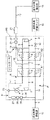
図1に示すように、本発明の実施形態に係る液体水素製造装置HSは、循環する水素(以下「循環水素」という。)を冷媒とする冷凍サイクル部Rと、水素ガス(以下「原料水素」という。)を冷凍サイクル部Rにより冷却した上で断熱膨張させて液体水素を生成する液体水素生成部Pとを備えている。
Hereinafter, embodiments of the present invention will be described in detail with reference to the accompanying drawings.
As shown in FIG. 1, a liquid hydrogen production apparatus HS according to an embodiment of the present invention includes a refrigeration cycle section R that uses circulating hydrogen (hereinafter referred to as “circulated hydrogen”) and hydrogen gas (hereinafter referred to as “raw material hydrogen”). ") Is cooled by the refrigeration cycle section R and then adiabatically expanded to generate liquid hydrogen, and a liquid hydrogen generation section P is provided.
冷凍サイクル部Rは、循環水素を循環して流通させる環状の水素循環通路1を備えている。水素循環通路1内においては、循環水素は、図1中における位置関係において時計回り方向に循環する。なお、以下では便宜上、循環水素の流れ方向に関して上流及び下流を、それぞれ単に「上流」及び「下流」という。そして、水素循環通路1には、コンプレッサ2と、該コンプレッサ2の下流に位置する循環水素冷却器3と、該循環水素冷却器3の下流に位置する膨張タービン4とが介設されている。 The refrigeration cycle section R includes an annular hydrogen circulation passage 1 that circulates and circulates circulating hydrogen. In the hydrogen circulation passage 1, the circulating hydrogen circulates clockwise in the positional relationship in FIG. In the following, for convenience, upstream and downstream in the direction of the circulating hydrogen flow are simply referred to as “upstream” and “downstream”, respectively. The hydrogen circulation passage 1 is provided with a compressor 2, a circulating hydrogen cooler 3 positioned downstream of the compressor 2, and an expansion turbine 4 positioned downstream of the circulating hydrogen cooler 3.
コンプレッサ2は、例えば電気モータによって駆動される圧縮機であり、常圧(例えば0.1MPaA)で常温(例えば300K)の循環水素を断熱圧縮して、高圧(例えば2MPaA)かつ高温(例えば780K)の状態にする。循環水素冷却器3は、例えば冷媒として低温の冷却水を用いる熱交換器であり、高圧で高温の循環水素を、その圧力を維持しつつ常温となるよう冷却する。なお、この高圧で常温の循環水素は、膨張タービン4に到達する前に、後で説明する第1熱交換器E1及び第2熱交換器E2により、圧力を維持しつつ非常に低温(例えば40K)となるよう冷却される。膨張タービン4は、高圧の気体の圧力エネルギーないしは運動エネルギーを機械的エネルギーに変換して取り出すタービンであり、高圧で非常に低温の循環水素によって駆動される一方、循環水素の圧力及び温度を低下させて循環水素の少なくとも一部を液化させ、常圧で極低温(例えば20K)の状態にする。なお、膨張タービン4に代えて、循環水素を断熱膨張させるジュールトムソン弁等の膨張機を用いてもよい。 The compressor 2 is a compressor driven by, for example, an electric motor, adiabatically compresses circulating hydrogen at normal temperature (for example, 0.1 MPaA) and normal temperature (for example, 300 K), and thereby high pressure (for example, 2 MPaA) and high temperature (for example, 780 K). To the state. The circulating hydrogen cooler 3 is, for example, a heat exchanger that uses low-temperature cooling water as a refrigerant, and cools high-pressure, high-temperature circulating hydrogen so as to reach a normal temperature while maintaining the pressure. In addition, before reaching the expansion turbine 4, this high-pressure, normal-temperature circulating hydrogen is kept at a very low temperature (for example, 40K) while maintaining the pressure by a first heat exchanger E1 and a second heat exchanger E2 described later. ). The expansion turbine 4 is a turbine that takes out pressure energy or kinetic energy of high-pressure gas by converting it into mechanical energy, and is driven by high-pressure and extremely low-temperature circulating hydrogen, while reducing the pressure and temperature of the circulating hydrogen. Thus, at least a part of the circulating hydrogen is liquefied and brought to a state of extremely low temperature (for example, 20 K) at normal pressure. Instead of the expansion turbine 4, an expander such as a Joule-Thomson valve that adiabatically expands the circulating hydrogen may be used.
さらに、水素循環通路1には、膨張タービン4より下流かつコンプレッサ2より上流の部位に第1、第2低温側熱交換部5、6が設けられる一方、循環水素冷却器3より下流かつ膨張タービン4より上流の部位に第1、第2高温側熱交換部7、8が設けられている。ここで、第1低温側熱交換部5と第1高温側熱交換部7とは、互いに対応する位置に配置され互いに熱交換する。また、第2低温側熱交換部6と第2高温側熱交換部8とは、互いに対応する位置に配置され互いに熱交換する。なお、第1低温側熱交換部5及び第1高温側熱交換部7は後で説明する第1熱交換器E1の構成要素であり、第2低温側熱交換部6及び第2高温側熱交換部8は後で説明する第2熱交換器E2の構成要素である。
Further, the hydrogen circulation passage 1 is provided with first and second low temperature side heat exchange sections 5 and 6 at a site downstream of the expansion turbine 4 and upstream of the compressor 2, while being downstream of the circulation hydrogen cooler 3 and the expansion turbine. First and second high temperature side
液体水素生成部Pは、原料水素供給源10から供給される高圧(例えば2MPaA)で常温の原料水素を流通させる原料水素通路11を備えている。そして、原料水素の流れ方向(図1中に示す位置関係では右向き)に関して原料水素通路11の下流端にジュールトムソン弁12が接続されている。さらに、原料水素通路11には、原料水素の流れ方向に関して上流から順に、第1原料水素冷却部13と第2原料水素冷却部14とが介設されている。ここで、第1原料水素冷却部13と第2原料水素冷却部14とは、高圧で常温の原料水素を、圧力をほぼ維持しつつ非常に低温(例えば40K)の状態に冷却する。また、ジュールトムソン弁12は、高圧で非常に低温の原料水素を断熱膨張させることによりその圧力及び温度を低下させ、原料水素の少なくとも一部を液化させて液体水素を生成する。なお、ジュールトムソン弁以外の膨張弁を用いて、原料水素を液化させてもよい。第1原料水素冷却部13は後で説明する第1熱交換器E1の構成要素であり、第2原料水素冷却部14は後で説明する第2熱交換器E2の構成要素である。
The liquid hydrogen generator P includes a raw material hydrogen passage 11 through which raw material hydrogen at normal temperature is circulated at a high pressure (for example, 2 MPaA) supplied from the raw material hydrogen supply source 10. A Joule-
液体水素製造装置HSには、冷凍サイクル部Rと液体水素生成部Pとにわたって、第1低温側熱交換部5と第1高温側熱交換部7と第1原料水素冷却部13とを構成要素とする第1熱交換器E1と、第2低温側熱交換部6と第2高温側熱交換部8と第2原料水素冷却部14とを構成要素とする第2熱交換器E2とが設けられている。第1熱交換器E1及び第2熱交換器E2は、いずれも、水素循環通路1の膨張タービン4より下流かつコンプレッサ2より上流の部位を流れている循環水素によって、水素循環通路1の循環水素冷却器3より下流かつ膨張タービン4より上流の部位を流れている循環水素を冷却するとともに、原料水素通路11を流れている原料水素を冷却する。
The liquid hydrogen production apparatus HS includes a first low temperature side heat exchange unit 5, a first high temperature side heat exchange unit 7, and a first raw material
なお、図1に示す実施形態では、冷凍サイクル部Rと液体水素生成部Pとにわたって2基の熱交換器E1、E2が設けられているだけであるが、かかる熱交換器の設置数は2基に限定されるものではなく、3基以上(例えば、3基、4基、5基……)の熱交換器を設けてもよい。すなわち、熱交換器の設置数は、各熱交換器の伝熱面積その他の熱交換特性に応じて好ましく設定される。 In the embodiment shown in FIG. 1, only two heat exchangers E1 and E2 are provided across the refrigeration cycle section R and the liquid hydrogen generation section P. However, the number of such heat exchangers installed is two. It is not limited to the group, and three or more (for example, three, four, five, etc.) heat exchangers may be provided. That is, the number of installed heat exchangers is preferably set according to the heat transfer area and other heat exchange characteristics of each heat exchanger.
以下、冷凍サイクル部R又は液体水素生成部P内を流れる循環水素及び原料水素の熱力学的状態がどのように変化するかを説明する。まず、水素循環通路1内を膨張タービン4からコンプレッサ2へ流れる循環水素の状態変化を説明する。膨張タービン4から流出した少なくとも一部が液化している常圧(例えば0.1MPaA)で極低温(例えば20K)の循環水素は、第2低温側熱交換部6を流通する際に、第2高温側熱交換部8内を流れている循環水素を冷却するとともに第2原料水素冷却器14内を流れている原料水素を冷却する。その結果、第2低温側熱交換部6(第2熱交換器E2)から流出する常圧の循環水素の温度はやや高い温度(例えば80K)に上昇する。なお、液化していた循環水素は第2低温側熱交換部6を流通する際に気化する。
Hereinafter, how the thermodynamic state of the circulating hydrogen and the raw material hydrogen flowing in the refrigeration cycle section R or the liquid hydrogen generation section P changes will be described. First, the state change of circulating hydrogen flowing from the expansion turbine 4 to the compressor 2 in the hydrogen circulation passage 1 will be described. The circulating hydrogen at an ordinary pressure (for example, 0.1 MPaA) and an extremely low temperature (for example, 20K) at least a part of which has flowed out of the expansion turbine 4 passes through the second low temperature side heat exchange section 6 when the second hydrogen is circulated. The circulating hydrogen flowing in the high temperature side
第2熱交換器E2(第2低温側熱交換部6)から流出した循環水素は、さらに第1低温側熱交換部5を流通する際に、第1高温側熱交換部7内を流れている循環水素を冷却するとともに第1原料水素冷却器13内を流れている原料水素を冷却する。その結果、第1熱交換器E1(第1低温側熱交換部5)から流出する常圧の循環水素の温度は常温(例えば300K)に上昇する。この後、常圧で常温の循環水素は、コンプレッサ2に流入し、コンプレッサ2によって断熱圧縮され、高圧(例えば2MPaA)で高温(例えば780K)の状態となる。
The circulating hydrogen flowing out from the second heat exchanger E2 (second low temperature side heat exchange unit 6) flows through the first high temperature side heat exchange unit 7 when flowing through the first low temperature side heat exchange unit 5. The circulating hydrogen being cooled is cooled, and the raw hydrogen flowing in the first
次に、水素循環通路1内をコンプレッサ2から膨張タービン4へ流れる循環水素の状態変化を説明する。コンプレッサ2から流出した高圧で高温の気体の循環水素は、まず循環水素冷却器3によって冷却され、常温(例えば300K)の状態となる。この高圧で常温の循環水素は、第1高温側熱交換部7を流通する際に、第1低温側熱交換部5内を流れている循環水素により冷却され、非常に低温(例えば80K)の状態となる。第1高温側熱交換部7(第1熱交換器E1)から流出した高圧で非常に低温の循環水素は、第2高温側熱交換部8を流通する際に、第2低温側熱交換部6内を流れている循環水素によって冷却され、さらに低温(例えば40K)の状態となる。この後、非常に低温となった高圧の循環水素は、膨張タービン4に流入し、膨張タービン4によって膨張させられ、少なくとも一部が液化している常圧(例えば0.1MPaA)で極低温(例えば20K)の状態となる。
Next, the state change of the circulating hydrogen flowing from the compressor 2 to the expansion turbine 4 in the hydrogen circulation passage 1 will be described. The high-pressure, high-temperature gas circulating hydrogen that has flowed out of the compressor 2 is first cooled by the circulating hydrogen cooler 3 to be at a normal temperature (for example, 300 K). This high-pressure, normal-temperature circulating hydrogen is cooled by circulating hydrogen flowing in the first low-temperature side heat exchange unit 5 when flowing through the first high-temperature side heat exchange unit 7, and has a very low temperature (for example, 80 K). It becomes a state. The high-pressure and very low-temperature circulating hydrogen that has flowed out of the first high-temperature side heat exchange unit 7 (first heat exchanger E1) flows through the second high-temperature side
さらに、原料水素通路11内を原料水素供給源10からジュールトムソン弁12へ流れる原料水素の状態変化を説明する。原料水素供給源10から供給された高圧(例えば2MPaA)で常温(例えば300K)の原料水素は、第1原料水素冷却部13を流通する際に、第1低温側熱交換部5内を流れている循環水素により冷却され、非常に低温(例えば80K)の状態となる。第1原料水素冷却部13(第1熱交換器E1)から流出した高圧で非常に低温の原料水素は、第2原料水素冷却部14を流通する際に、第2低温側熱交換部6内を流れている循環水素によって冷却され、さらに低温(例えば40K)の状態となる。
Furthermore, the state change of the raw material hydrogen flowing from the raw material hydrogen supply source 10 to the Joule-
この後、非常に低温となった高圧の原料水素は、ジュールトムソン弁12を通過する際にジュールトムソン膨張させられ、少なくとも一部が液化している常圧(例えば0.1MPaA)で極低温(例えば20K)の状態となる。ここで、液化した原料水素は、この液体水素製造装置HSの生成物である液体水素であり、液体水素貯蔵タンク15に貯蔵される。液体水素貯蔵タンク15に貯蔵されている液体水素は、適宜に、該液体水素製造装置HSの所在地の近傍の港(積荷港)に停泊している液体水素輸送船16の液体水素貯槽に充填される。
After that, the high-pressure raw material hydrogen that has become extremely low temperature is expanded by Joule-Thompson expansion when passing through the Joule-
表1に、図1中にa〜kで示す、冷凍サイクル部R又は液体水素生成部P内の各部位における循環水素又は原料水素の熱力学的状態をまとめて示す。なお、表1中において「G」は気体を意味し、「L」は液体を意味する。

本発明に係る液体水素製造装置HSは、さらに該液体水素製造装置HSの所在地の近傍の港(積荷港)に停泊している液体水素輸送船16の液体水素貯槽(図示せず)で発生するボイルオフガスを導入する一方、このボイルオフガスを再液化して液体水素を生成するためのボイルオフガス処理機構を備えている。まず、このボイルオフガス処理機構の基本的な構成及び機能を説明する。要するに、本発明に係る液体水素製造装置HSのボイルオフガス処理機構は、冷凍サイクル部の水素循環通路中の循環水素が低温で流れる部位に低温のボイルオフガスを導入する一方、ボイルオフガスの導入により生じた余剰の循環水素を、冷凍サイクル部の水素循環通路中の循環水素が常温で流れる部位から排出し、液体水素生成部の原料水素通路中の原料水素が常温で流れる部位に供給して原料水素と混合することにより、ボイルオフガスを再液化して液体水素として再利用するものである。
The liquid hydrogen production apparatus HS according to the present invention is further generated in a liquid hydrogen storage tank (not shown) of the liquid
ボイルオフガス処理機構は、ボイルオフガス導入部Cと循環水素排出部Dとを備えている。ここで、ボイルオフガス導入部Cは、液体水素輸送船16の液体水素貯槽で発生する非常に低温のボイルオフガスを、膨張タービン4より下流かつコンプレッサ2より上流の部位で水素循環通路1に導入する。このボイルオフガス導入部Cは、後で説明するように、水素循環通路1へのボイルオフガスの導入部位を、ボイルオフガスの導入部位における循環水素の温度とボイルオフガスの温度の差が最小となるよう、ボイルオフガスの温度に応じて切り換える。
The boil-off gas processing mechanism includes a boil-off gas introduction part C and a circulating hydrogen discharge part D. Here, the boil-off gas introduction section C introduces a very low temperature boil-off gas generated in the liquid hydrogen storage tank of the liquid
他方、循環水素排出部Dは、水素循環通路1内の常温の循環水素を、原料水素の流れ方向に関して第1原料水素冷却部13より上流の原料水素通路11へ排出し、常温の原料水素に混合する。すなわち、循環水素排出部Dは、ボイルオフガスの導入により生じる余剰の循環水素を、第1低温側熱交換部5とコンプレッサ2との間の水素循環通路1、又は循環水素冷却器3と第1高温側熱交換部7との間の水素循環通路1から原料水素通路11へ排出する。なお、図1に示す実施形態では、余剰の循環水素を、循環水素冷却器3と第1高温側熱交換部7との間の水素循環通路1から原料水素通路11へ排出するようにしている。
On the other hand, the circulating hydrogen discharge unit D discharges the normal temperature circulating hydrogen in the hydrogen circulation passage 1 to the raw material hydrogen passage 11 upstream from the first raw
以下、ボイルオフガス処理機構の具体的な構成及び機能を説明する。ボイルオフガス導入部Cは、液体水素輸送船16の液体水素貯槽で発生した常圧(例えば0.1MPaA)で非常に低温のボイルオフガスを液体水素製造装置HSにパイプ輸送するボイルオフガス導入通路17を有している。なお、図示していないが、外部からの入熱によるボイルオフガスの温度の上昇を防止するため、ボイルオフガス導入通路17の周囲は断熱されている。そして、ボイルオフガスの流れ方向に関してボイルオフガス導入通路17の下流端には、切換弁18を介して、第1ボイルオフガス供給通路19と第2ボイルオフガス供給通路20とが接続されている。切換弁18は、ボイルオフガス導入通路17を、第1ボイルオフガス供給通路19又は第2ボイルオフガス供給通路20に択一的に接続し、又はボイルオフガス導入通路17を閉止する。
Hereinafter, a specific configuration and function of the boil-off gas processing mechanism will be described. The boil-off gas introduction part C has a boil-off
ボイルオフガスの流れ方向に関して、第1ボイルオフガス供給通路19の下流端は第1低温側熱交換部5と第2低温側熱交換部6との間の水素循環通路1に接続される一方、第2ボイルオフガス供給通路20の下流端は第2低温側熱交換部6と膨張タービン4との間の水素循環通路1に接続されている。したがって、ボイルオフガス導入部Cは、切換弁18の通路接続態様を切り換えることにより、ボイルオフガス導入通路17内のボイルオフガスを、第1低温側熱交換部5と第2低温側熱交換部6との間の水素循環通路1、又は第2低温側熱交換部6と膨張タービン4との間の水素循環通路1のいずれか一方に択一的に供給することができる。
Regarding the flow direction of the boil-off gas, the downstream end of the first boil-off
さらに、ボイルオフガスの流れ方向に関して切換弁18より上流の部位において、ボイルオフガス導入通路17には、上流側から順に、ボイルオフガスを下流側に送る圧縮比が非常に低いブロワ21(又は圧縮機)と、ボイルオフガス導入通路17内を流れているボイルオフガスの流量を検出する第1流量センサ22と、ボイルオフガスの温度を検出する温度センサ23とが設けられている。第1流量センサ22の検出値及び温度センサ23の検出値は、後で説明するコントローラ24に入力される。液体水素輸送船16の液体水素貯槽で発生するボイルオフガスは常圧であり、またボイルオフガスが供給される部位では水素循環通路1内の循環水素は常圧であるので、圧縮比が非常に低いブロワ21でボイルオフガスを容易に水素循環通路1に供給することができる。このとき、ボイルオフガスはほとんど圧縮されないので、ボイルオフガスの温度はほとんど変化しない。なお、ボイルオフガスの圧力が、該ボイルオフガスが導入される部位における循環水素の圧力より高い場合は、ブロワ21は省略してもよい。
Further, in a portion upstream of the switching
他方、循環水素排出部Dは、開閉弁25を介して、循環水素冷却器3と第1高温側熱交換部7との間の水素循環通路1と、原料水素の流れ方向に関して第1原料水素冷却部13より上流の原料水素通路11とを接続する循環水素排出通路26を有している。開閉弁25は、循環水素冷却器3と第1高温側熱交換部7との間の水素循環通路1を循環水素排出通路26に接続し、又は水素循環通路1と循環水素排出通路26との接続を遮断する。
On the other hand, the circulating hydrogen discharge unit D is connected to the first raw material hydrogen with respect to the hydrogen circulation passage 1 between the circulating hydrogen cooler 3 and the first high temperature side heat exchange unit 7 and the flow direction of the raw material hydrogen via the on-off
さらに、循環水素排出通路26には、水素循環通路1から排出される循環水素の流れ方向に関して上流側から順に、排出された循環水素を下流側に送る圧縮機27と、循環水素排出通路26内を流れる循環水素の流量を制御する流量制御弁28と、循環水素排出通路26内を流れる循環水素の流量を検出する第2流量センサ29とが設けられている。第2流量センサ29の検出値はコントローラ24に入力される。なお、循環水素冷却器3と第1高温側熱交換部7との間の水素循環通路1内の循環水素と、第1原料水素冷却部13より上流の原料水素通路11内の原料水素は、いずれも高圧であるが、圧力は互いにほぼ等しいので、圧縮比が非常に低い圧縮機27で循環水素を容易に原料水素通路11に排出することができる。このとき、循環水素はほとんど圧縮されないので、循環水素の温度はほとんど変化しない。なお、この部位における循環水素の圧力が原料水素の圧力より高い場合は、圧縮機27を省略してもよい。
Further, the circulating
コントローラ24は、コンピュータを備えたボイルオフガス処理機構の総合的な制御装置であり、第1流量センサ22によって検出されるボイルオフガスの流量と、温度センサ23によって検出されるボイルオフガスの温度と、第2流量センサ29によって検出される循環水素の流量とを制御情報として、切換弁18とブロワ21と開閉弁25と圧縮機27と流量制御弁28とを制御する。以下、コントローラ24によるボイルオフガス処理機構の制御手法を具体的に説明する。
The
液体水素輸送船16が、その液体水素貯槽に適量(例えば、輸送船の液体水素貯槽の体積の数vol%)の保冷用の液体水素を残して、液体水素貯蔵タンク15の近傍の積荷港に到着して停泊すると、液体水素貯蔵タンク15から液体水素輸送船16の液体水素貯槽(以下「輸送船貯槽」という。)に液体水素が充填される。なお、液体水素輸送船16の停泊期間は、通常、1日ないし数日であると考えられる。このとき、輸送船貯槽の温度、とくに輸送船貯槽の上部の温度は、航行時又は停泊時における貯槽外部からの入熱により、液体水素の飽和温度よりも高くなっている。
The liquid
このため、輸送船貯槽の温度と充填される液体水素の温度の差により、液体水素の一部が気化し、短期間に大量のボイルオフガスが発生する。一般に、輸送船貯槽で発生するブローオフガスの温度は、液体水素の充填開始時では50〜80Kである。そして、輸送船貯槽の液体水素の充填率が高くなると、輸送船貯槽は液体水素によって冷却され、輸送船貯槽の温度が徐々に低下するので、ブローオフガスの温度は20〜50Kとなり、水素の液化温度に近い温度となる。 For this reason, due to the difference between the temperature of the transport ship storage tank and the temperature of liquid hydrogen to be filled, part of the liquid hydrogen is vaporized, and a large amount of boil-off gas is generated in a short time. Generally, the temperature of the blow-off gas generated in the transport ship storage tank is 50 to 80 K at the start of filling with liquid hydrogen. When the filling rate of liquid hydrogen in the transport ship storage tank becomes high, the transport ship storage tank is cooled by liquid hydrogen, and the temperature of the transport ship storage tank gradually decreases, so the temperature of the blow-off gas becomes 20 to 50K, and the liquefaction of hydrogen The temperature is close to the temperature.
かくして、コントローラ24によってブロワ21が起動され、輸送船貯槽で発生した非常に低温(例えば、20〜80K)のボイルオフガスは、ボイルオフガス導入通路17を経由して、ほぼその温度を維持しつつ液体水素製造装置HSに導入される。その際、温度センサ23によって検出されたボイルオフガスの温度が比較的高く50K以上であるとき、例えば50K以上かつ80K以下であるときは、コントローラ24は、切換弁18を、ボイルオフガス導入通路17が第1ボイルオフガス供給通路19に接続されるように制御する。他方、温度センサ22によって検出されたボイルオフガスの温度が比較的低く50未満であるとき、例えば20K以上かつ50K未満であるときは、コントローラ24は、切換弁18を、ボイルオフガス導入通路17が第2ボイルオフガス供給通路20に接続されるように制御する。なお、液体水素製造装置HSにボイルオフガスを導入しないときには、コントローラ24は、ブロワ21を停止させる一方、切換弁18を、ボイルオフガス導入通路17が閉止されるように制御する。
Thus, the
つまり、ボイルオフガスの温度が比較的高温であるとき、例えば50K以上かつ80K以下であるときには、ボイルオフガスは、第1低温側熱交換部5と第2低温側熱交換部6との間の水素循環通路1内の例えば80Kの循環水素と混合される。他方、ボイルオフガスの温度が比較的低温であるとき、例えば20K以上かつ50K未満であるときには、ボイルオフガスは、第2低温側熱交換部6と膨張タービン4との間の水素循環通路1内の例えば20Kの循環水素と混合される。このように、水素循環通路1へのボイルオフガスの導入部位は、ボイルオフガスの導入部位における循環水素の温度とボイルオフガスの温度の差が最小となるよう、ボイルオフガスの温度に応じて切り換えられる。このため、水素循環通路1内における循環水素の温度分布にとくには影響を及ぼさない。このように、ボイルオフガスは、輸送船貯槽で発生したときと同様の非常に低温の状態で水素循環通路1に導入されるので、ボイルオフガスの冷熱を無駄にすることがない。 That is, when the temperature of the boil-off gas is relatively high, for example, when the temperature is 50 K or more and 80 K or less, the boil-off gas is hydrogen between the first low temperature side heat exchange unit 5 and the second low temperature side heat exchange unit 6. It is mixed with, for example, 80 K of circulating hydrogen in the circulation passage 1. On the other hand, when the temperature of the boil-off gas is relatively low, for example, 20 K or more and less than 50 K, the boil-off gas is contained in the hydrogen circulation passage 1 between the second low-temperature side heat exchange unit 6 and the expansion turbine 4. For example, mixed with 20K of circulating hydrogen. In this way, the boil-off gas introduction site into the hydrogen circulation passage 1 is switched according to the boil-off gas temperature so that the difference between the circulating hydrogen temperature and the boil-off gas temperature at the boil-off gas introduction site is minimized. For this reason, the temperature distribution of the circulating hydrogen in the hydrogen circulation passage 1 is not particularly affected. As described above, since the boil-off gas is introduced into the hydrogen circulation passage 1 at a very low temperature similar to that generated in the transport ship storage tank, the cooling heat of the boil-off gas is not wasted.
ボイルオフガスを、輸送船貯槽で発生したときと同様の非常に低温の状態で水素循環通路1に導入した場合は、ボイルオフガスを常温(300K)まで加熱して原料水素通路11に導入する場合に比べて、液体水素製造装置HSのエネルギー効率を大幅に向上させることができる。例えば、ボイルオフガスの流量及び温度を、それぞれ0.53kg/s及び20Kとした場合、水素の熱容量は14.4kJ/(kg・K)であるので、下記の式で示すように、およそ2.1MWのエネルギーを低減することができる。ここで、液体水素製造装置HSの消費電力が20.0MWである場合、約10.5%程度のエネルギー効率の向上が見込まれる。
14.4[kJ/(kg・K)]×0.53[kg/s]×280[K]=2130[kJ/s]=2.1[MW]
When the boil-off gas is introduced into the hydrogen circulation passage 1 at a very low temperature similar to that generated in the transport ship storage tank, the boil-off gas is heated to room temperature (300 K) and introduced into the raw material hydrogen passage 11. In comparison, the energy efficiency of the liquid hydrogen production apparatus HS can be greatly improved. For example, when the flow rate and temperature of the boil-off gas are 0.53 kg / s and 20 K, respectively, the heat capacity of hydrogen is 14.4 kJ / (kg · K). Therefore, as shown by the following formula, approximately 2. The energy of 1 MW can be reduced. Here, when the power consumption of the liquid hydrogen production apparatus HS is 20.0 MW, an improvement in energy efficiency of about 10.5% is expected.
14.4 [kJ / (kg · K)] × 0.53 [kg / s] × 280 [K] = 2130 [kJ / s] = 2.1 [MW]
熱交換器の数が2基より多い場合は、これに対応してボイルオフガス供給通路を増やすとともに、ボイルオフガス導入通路17をこれらのボイルオフガス供給通路のいずれか1つと択一的に接続させることができるように構成された切換弁を設け、コントローラ24によりボイルオフガスの温度に応じて、ボイルオフガスの導入部位における循環水素の温度とボイルオフガスの温度の差が最小となるよう切換弁を制御すればよい。
When the number of heat exchangers is more than two, the boil-off gas supply passages are correspondingly increased and the boil-off
例えば、熱交換器の数がN基(N≧3)である場合、すなわちN個の低温側熱交換部が設けられている場合は、各低温側熱交換部間の水素循環通路11と、最も上流の低温側熱交換部と膨張タービン4との間の水素循環通路11とに、合計N個のボイルオフガス供給通路を接続し、これらを択一的に選択することができる切換弁を設ければよい。なお、熱交換器の数がN基(N≧3)である場合、ボイルオフガス供給通路の数は2以上であればN個より少なくてもよい。 For example, when the number of heat exchangers is N (N ≧ 3), that is, when N low-temperature side heat exchange units are provided, the hydrogen circulation passage 11 between the low-temperature side heat exchange units, A total of N boil-off gas supply passages are connected to the hydrogen circulation passage 11 between the most upstream low temperature side heat exchange section and the expansion turbine 4, and a switching valve is provided that can selectively select these. Just do it. When the number of heat exchangers is N (N ≧ 3), the number of boil-off gas supply passages may be less than N as long as the number is 2 or more.
前記のようにボイルオフガスが水素循環通路1に導入されると、水素循環通路1内の循環水素はその分だけ過剰となり、余剰の循環水素が生じることになる。そこで、コントローラ24は、ボイルオフガスが水素循環通路1に導入されているときには、圧縮機27を起動するとともに、開閉弁25を、循環水素冷却器3と第1高温側熱交換部7との間の水素循環通路1と循環水素排出通路26とが接続されるように制御する。
When the boil-off gas is introduced into the hydrogen circulation passage 1 as described above, the circulation hydrogen in the hydrogen circulation passage 1 becomes excessive by that amount, and surplus circulation hydrogen is generated. Therefore, when the boil-off gas is introduced into the hydrogen circulation passage 1, the
さらに、コントローラ24は、第2流量センサ29によって検出される循環水素の流量が、第1流量センサ22によって検出されたボイルオフガスの流量と一致するよう流量制御弁28を制御する。例えば、流量制御弁28の弁開度を変化させる。これにより、水素循環通路1に導入されたボイルオフガスの量と等しい量の循環水素が、水素循環通路1から原料水素通路11に排出され、原料水素と混合される。したがって、水素循環通路1内の循環水素の量は適正値に維持される。なお、輸送船貯槽から水素循環通路1へのボイルオフガスの導入が停止されたときには、コントローラ24は、圧縮機27を停止させる一方、開閉弁25を、水素循環通路1と循環水素排出通路26の接続が遮断されるように制御する。
Further, the
ここで、循環水素排出通路26を経由して、水素循環通路1から原料水素通路11に排出される循環水素は常温であるので、原料水素通路11内を流れている原料水素の温度を低下させない。したがって、このような循環水素の原料水素通路11との混合は、常温の原料水素を供給することを前提として設計されている液体水素生成部Pないしは液体水素製造装置HSに何ら不具合を生じさせない。
Here, since the circulating hydrogen discharged from the hydrogen circulation passage 1 to the raw hydrogen passage 11 through the circulating
以上、本発明の実施形態に係る液体水素製造装置HSによれば、その構成要素に何ら不具合を生じさせることなく、液体水素製造装置HSに非常に低温のボイルオフガスを導入して、ボイルオフガスの導入量に相当する液体水素を生成することができる。すなわち、実質的には、輸送船貯槽で短期間に大量に発生する非常に低温のボイルオフガスを、その冷熱エネルギーを無駄にすることなく有効に活用して液化させ、液体水素として再利用することができる。 As described above, according to the liquid hydrogen production apparatus HS according to the embodiment of the present invention, a very low temperature boil-off gas is introduced into the liquid hydrogen production apparatus HS without causing any trouble in its constituent elements. Liquid hydrogen corresponding to the introduced amount can be generated. In other words, the extremely low-temperature boil-off gas that is generated in large quantities in a short time in a transport ship storage tank can be effectively liquefied without wasting its cold energy and reused as liquid hydrogen. Can do.
前記のとおり、図1に示す実施形態では、水素循環通路1へのボイルオフガスの導入により生じる余剰の循環水素を、循環水素冷却器3と第1高温側熱交換部7との間の水素循環通路1から、原料水素の流れ方向に関して第1原料水素冷却器13より上流の原料水素通路11に排出するようにしている。しかしながら、第1低温側熱交換部5とコンプレッサ2との間の水素循環通路1内の循環水素は常温であるので、水素循環通路1中のこの部位と、原料水素の流れ方向に関して第1原料水素冷却器13より上流の原料水素通路11との間を接続する循環水素排出通路を設け、この循環水素排出通路を経由して余剰の循環水素を原料水素通路11に排出するようにしてもよい。
As described above, in the embodiment shown in FIG. 1, surplus circulating hydrogen generated by the introduction of the boil-off gas into the hydrogen circulation passage 1 is circulated between the circulating hydrogen cooler 3 and the first high temperature side heat exchange unit 7. From the passage 1, the raw material hydrogen is discharged to the raw material hydrogen passage 11 upstream from the first raw material hydrogen cooler 13 in the flow direction of the raw material hydrogen. However, since the circulating hydrogen in the hydrogen circulation passage 1 between the first low-temperature side heat exchange section 5 and the compressor 2 is at room temperature, the first raw material with respect to this portion in the hydrogen circulation passage 1 and the flow direction of the raw material hydrogen. A circulating hydrogen discharge passage that connects the raw material hydrogen passage 11 upstream from the
この場合、第1低温側熱交換部5とコンプレッサ2の間の水素循環通路1内の循環水素は常圧である一方、原料水素通路11内の原料水素は高圧であるので、循環水素排出通路に、常圧の循環水素を原料水素と同様の高圧状態に加圧するコンプレッサと、このコンプレッサの断熱圧縮により高温(例えば780K)となる循環水素を冷却する冷却器とを設ける必要がある。なお、この場合も、図1に示す液体水素製造装置HSと同様に、開閉弁と流量制御弁と流量センサとを設ける必要がある。 In this case, the circulating hydrogen in the hydrogen circulation passage 1 between the first low temperature side heat exchange section 5 and the compressor 2 is at a normal pressure, while the raw hydrogen in the raw hydrogen passage 11 is at a high pressure. In addition, it is necessary to provide a compressor that pressurizes the normal-pressure circulating hydrogen to a high pressure state similar to that of the raw hydrogen, and a cooler that cools the circulating hydrogen that becomes high temperature (for example, 780 K) by adiabatic compression of the compressor. Also in this case, it is necessary to provide an on-off valve, a flow rate control valve, and a flow rate sensor, similarly to the liquid hydrogen production apparatus HS shown in FIG.
以上のように、本発明に係る液体水素製造装置は、例えば褐炭等の低品位炭を主原料として生成された水素を原料として液体水素を製造する装置として有用であり、とくに液体水素を液体水素輸送船で需要地に輸送する場合において、液体水素輸送船の液体水素貯槽に液体水素を充填する際に発生するボイルオフガスを再液化させて再利用するのに適している。 As described above, the liquid hydrogen production apparatus according to the present invention is useful as an apparatus for producing liquid hydrogen from hydrogen produced using, for example, low-grade coal such as lignite as a main raw material. When transporting to a demand place by a transport ship, it is suitable for re-liquefying and reusing the boil-off gas generated when the liquid hydrogen storage tank of the liquid hydrogen transport ship is filled with liquid hydrogen.
HS 液体水素製造装置、R 冷凍サイクル部、P 液体水素生成部、E1 第1熱交換器、E2 第2熱交換器、C ボイルオフガス導入部、D 循環水素排出部、1 水素循環通路、2 コンプレッサ、3 循環水素冷却器、4 膨張タービン、5 第1低温側熱交換部、6 第2低温側熱交換部、7 第1高温側熱交換部、8 第2高温側熱交換部、10 原料水素供給源、11 原料水素通路、12 ジュールトムソン弁、13 第1原料水素冷却部、14 第2原料水素冷却部、15 液体水素貯蔵タンク、16 液体水素輸送船、17 ボイルオフガス導入通路、18 切換弁、19 第1ボイルオフガス供給通路、20 第2ボイルオフガス供給通路、21 ブロワ、22 第1流量センサ、23 温度センサ、24 コントローラ、25 開閉弁、26 循環水素排出通路、27 圧縮機、28 流量制御弁、29 第2流量センサ。
HS liquid hydrogen production apparatus, R refrigeration cycle section, P liquid hydrogen generation section, E1 first heat exchanger, E2 second heat exchanger, C boil-off gas introduction section, D circulating hydrogen discharge section, 1 hydrogen circulation path, 2 compressor 3 circulating hydrogen cooler 4 expansion turbine 5 first low temperature side heat exchange section 6 second low temperature side heat exchange section 7 first high temperature side
Claims (7)
液体水素貯槽の内部で発生するボイルオフガスを、冷凍サイクル部の所定の導入箇所に導入するボイルオフガス導入部と、
前記ボイルオフガス導入部から導入されたボイルオフガスに起因する余剰の循環水素を、冷凍サイクル部の所定の排出箇所から液体水素生成部に排出する循環水素排出部と、を備えることを特徴とする液体水素製造装置。 A liquid hydrogen production apparatus comprising a refrigeration cycle unit using circulating hydrogen as a refrigerant, and a liquid hydrogen generation unit that generates liquid hydrogen from hydrogen gas,
A boil-off gas introduction part that introduces boil-off gas generated inside the liquid hydrogen storage tank into a predetermined introduction part of the refrigeration cycle part;
A circulating hydrogen discharge unit that discharges excess circulating hydrogen caused by the boil-off gas introduced from the boil-off gas introduction unit from a predetermined discharge point of the refrigeration cycle unit to the liquid hydrogen generation unit. Hydrogen production equipment.
前記循環する水素を圧縮するコンプレッサと、
前記循環する水素を膨張させる膨張機と、
前記コンプレッサと前記膨張機との間に設けられ、前記コンプレッサの上流側にある低温側熱交換部と前記コンプレッサの下流側にある高温側熱交換部とから成る1組以上の熱交換部と、を有し、
前記液体水素生成部は、
原料水素供給源から供給された水素ガスを流通させる原料水素通路と、
前記原料水素通路の下流に設けられ、水素ガスを膨張させて液体水素を生成する膨張弁と、
前記冷凍サイクル部の前記1組以上の熱交換部と熱交換して水素ガスを冷却する1以上の水素ガス冷却部と、を有し、
前記冷凍サイクル部の所定の導入箇所は、前記膨張機より下流側かつ前記コンプレッサより上流側に位置し、
前記冷凍サイクル部の所定の排出箇所は、前記コンプレッサの上流側に位置する最初の低温側熱交換部と前記コンプレッサの下流側に位置する最初の高温側熱交換部との間に位置することを特徴とする、請求項1に記載の液体水素製造装置。 The refrigeration cycle section
A compressor for compressing the circulating hydrogen;
An expander for expanding the circulating hydrogen;
One or more sets of heat exchanging units, which are provided between the compressor and the expander, and each include a low temperature side heat exchanging unit on the upstream side of the compressor and a high temperature side heat exchanging unit on the downstream side of the compressor, Have
The liquid hydrogen generator is
A raw material hydrogen passage for circulating hydrogen gas supplied from a raw material hydrogen supply source;
An expansion valve that is provided downstream of the raw hydrogen passage and expands hydrogen gas to produce liquid hydrogen;
And one or more hydrogen gas cooling units that cool the hydrogen gas by exchanging heat with the one or more heat exchange units of the refrigeration cycle unit,
The predetermined introduction location of the refrigeration cycle unit is located downstream from the expander and upstream from the compressor,
The predetermined discharge point of the refrigeration cycle unit is located between the first low temperature side heat exchange unit located on the upstream side of the compressor and the first high temperature side heat exchange unit located on the downstream side of the compressor. The liquid hydrogen production apparatus according to claim 1, wherein the liquid hydrogen production apparatus is characterized.
Priority Applications (5)
| Application Number | Priority Date | Filing Date | Title |
|---|---|---|---|
| JP2012116764A JP5890748B2 (en) | 2012-05-22 | 2012-05-22 | Liquid hydrogen production equipment |
| AU2013264211A AU2013264211B2 (en) | 2012-05-22 | 2013-04-17 | Liquid hydrogen production device |
| PCT/JP2013/061414 WO2013175905A1 (en) | 2012-05-22 | 2013-04-17 | Liquid hydrogen production device |
| US14/376,504 US20150068246A1 (en) | 2012-05-22 | 2013-04-17 | Liquid hydrogen production device |
| RU2014125729/06A RU2573423C1 (en) | 2012-05-22 | 2013-04-17 | Liquid hydrogen producing device |
Applications Claiming Priority (1)
| Application Number | Priority Date | Filing Date | Title |
|---|---|---|---|
| JP2012116764A JP5890748B2 (en) | 2012-05-22 | 2012-05-22 | Liquid hydrogen production equipment |
Publications (2)
| Publication Number | Publication Date |
|---|---|
| JP2013242113A true JP2013242113A (en) | 2013-12-05 |
| JP5890748B2 JP5890748B2 (en) | 2016-03-22 |
Family
ID=49623606
Family Applications (1)
| Application Number | Title | Priority Date | Filing Date |
|---|---|---|---|
| JP2012116764A Active JP5890748B2 (en) | 2012-05-22 | 2012-05-22 | Liquid hydrogen production equipment |
Country Status (5)
| Country | Link |
|---|---|
| US (1) | US20150068246A1 (en) |
| JP (1) | JP5890748B2 (en) |
| AU (1) | AU2013264211B2 (en) |
| RU (1) | RU2573423C1 (en) |
| WO (1) | WO2013175905A1 (en) |
Cited By (4)
| Publication number | Priority date | Publication date | Assignee | Title |
|---|---|---|---|---|
| JP2018009651A (en) * | 2016-07-14 | 2018-01-18 | 株式会社日立プラントメカニクス | High-pressure hydrogen expansion turbine type filling system |
| DE112021007074T5 (en) | 2021-04-09 | 2023-11-23 | Honda Motor Co., Ltd. | FUEL CELL POWER SOURCE MANAGEMENT APPARATUS AND FUEL CELL POWER SOURCE MANAGEMENT METHOD |
| DE112021007032T5 (en) | 2021-04-09 | 2023-11-23 | Honda Motor Co., Ltd. | MANAGEMENT DEVICE AND METHOD FOR MANAGING FUEL CELL PERFORMANCE |
| DE112021007056T5 (en) | 2021-04-09 | 2024-02-22 | Honda Motor Co., Ltd. | MANAGEMENT DEVICE AND METHOD FOR MANAGING THE POWER SUPPLY OF FUEL CELLS |
Families Citing this family (18)
| Publication number | Priority date | Publication date | Assignee | Title |
|---|---|---|---|---|
| CN105318190B (en) * | 2014-08-05 | 2019-03-15 | 安瑞科(廊坊)能源装备集成有限公司 | BOG liquefaction recovery system and method |
| DE102015009255A1 (en) * | 2015-07-16 | 2017-01-19 | Linde Aktiengesellschaft | Method for cooling a process stream |
| RU2713556C1 (en) * | 2016-03-10 | 2020-02-05 | ДжГК Корпорейшн | New production equipment and method of producing liquefied hydrogen and liquefied natural gas |
| CN110462319B (en) * | 2017-03-28 | 2022-03-18 | 巴特尔纪念研究所 | Active magnetic regeneration process and system using hydrogen heat transfer fluid |
| US11193696B2 (en) | 2017-03-28 | 2021-12-07 | Battelle Memorial Institute | Advanced multi-layer active magnetic regenerator systems and processes for magnetocaloric liquefaction |
| CN107575735A (en) * | 2017-09-21 | 2018-01-12 | 成都华气厚普机电设备股份有限公司 | Automatic control system and control method with hydrogen recovery function hydrogenation plant |
| CN107575736A (en) * | 2017-09-21 | 2018-01-12 | 成都华气厚普机电设备股份有限公司 | A kind of control method of band remnants hydrogen diffusion function hydrogenation plant |
| CN108679929B (en) * | 2018-05-28 | 2024-05-03 | 张家港氢云新能源研究院有限公司 | Hydrogen liquefaction system with hydrogen component detection function |
| CN108534462B (en) * | 2018-05-28 | 2024-01-02 | 张家港氢云新能源研究院有限公司 | Liquid hydrogen production line |
| CN108547669A (en) * | 2018-05-28 | 2018-09-18 | 张家港富瑞氢能装备有限公司 | A kind of liquefaction of hydrogen hydrogen Turbine expansion unit |
| CN110185599A (en) * | 2019-06-19 | 2019-08-30 | 沈阳理工大学 | New hydrogen circulating hydrogen compressor |
| US11959699B2 (en) | 2020-03-02 | 2024-04-16 | Eta Space LLC | Water electrolysis and cryogenic liquefaction system |
| EP4267898A1 (en) * | 2020-12-22 | 2023-11-01 | Caterpillar Inc. | Cryogenic containment system |
| US20220196323A1 (en) * | 2020-12-22 | 2022-06-23 | Caterpillar Inc. | Cryogenic Containment System |
| US11391511B1 (en) * | 2021-01-10 | 2022-07-19 | JTurbo Engineering & Technology, LLC | Methods and systems for hydrogen liquefaction |
| CN114688445B (en) * | 2022-04-25 | 2023-10-27 | 液空厚普氢能源装备有限公司 | Hydrogen liquid hydrogen hydrogenation station |
| CN115419829B (en) * | 2022-08-25 | 2023-05-23 | 北京航天试验技术研究所 | High-pressure liquid hydrogen conveying system and method for liquid hydrogen engine test |
| US20240113594A1 (en) * | 2022-09-30 | 2024-04-04 | Sapphire Technologies, Inc. | Hydrogen applications for turboexpander machines |
Citations (2)
| Publication number | Priority date | Publication date | Assignee | Title |
|---|---|---|---|---|
| JP2003081605A (en) * | 2001-09-05 | 2003-03-19 | Kawasaki Heavy Ind Ltd | Hydrogen producing method accompanying recovery of liquefied co2 |
| JP2005241232A (en) * | 2004-01-27 | 2005-09-08 | Kansai Electric Power Co Inc:The | Hydrogen liquefying device, and liquid hydrogen manufacturing system |
Family Cites Families (9)
| Publication number | Priority date | Publication date | Assignee | Title |
|---|---|---|---|---|
| US3092461A (en) * | 1960-01-20 | 1963-06-04 | Air Prod & Chem | Process for producing liquid hydrogen |
| FR1370321A (en) * | 1962-10-01 | 1964-08-21 | Allied Chem | Process of cooling by adiabatic expansion of a compressed gaseous refrigerant, through a series of expansion valves connected in parallel, in a refrigeration zone with several stages |
| US4637216A (en) * | 1986-01-27 | 1987-01-20 | Air Products And Chemicals, Inc. | Method of reliquefying cryogenic gas boiloff from heat loss in storage or transfer system |
| US6276167B1 (en) * | 1999-03-25 | 2001-08-21 | Westlake Technology Corporation | Refrigeration production |
| FR2852590B1 (en) * | 2003-03-20 | 2005-06-17 | Snecma Moteurs | POWER SUPPLYING A GAS TERMINAL FROM A SHIP TRANSPORTING LIQUEFIED GAS |
| DE10352128A1 (en) * | 2003-11-04 | 2005-06-09 | Dylla, Anett, Dipl.-Ing. | Multifunctional power grid and devices for this |
| US7699174B2 (en) * | 2007-06-26 | 2010-04-20 | Tyco Electronics Corporation | Electrical connector interfaced with conductive ink on a cardboard substrate |
| US20090019886A1 (en) * | 2007-07-20 | 2009-01-22 | Inspired Technologies, Inc. | Method and Apparatus for liquefaction of a Gas |
| NO328493B1 (en) * | 2007-12-06 | 2010-03-01 | Kanfa Aragon As | System and method for regulating the cooling process |
-
2012
- 2012-05-22 JP JP2012116764A patent/JP5890748B2/en active Active
-
2013
- 2013-04-17 WO PCT/JP2013/061414 patent/WO2013175905A1/en active Application Filing
- 2013-04-17 RU RU2014125729/06A patent/RU2573423C1/en active
- 2013-04-17 US US14/376,504 patent/US20150068246A1/en not_active Abandoned
- 2013-04-17 AU AU2013264211A patent/AU2013264211B2/en active Active
Patent Citations (2)
| Publication number | Priority date | Publication date | Assignee | Title |
|---|---|---|---|---|
| JP2003081605A (en) * | 2001-09-05 | 2003-03-19 | Kawasaki Heavy Ind Ltd | Hydrogen producing method accompanying recovery of liquefied co2 |
| JP2005241232A (en) * | 2004-01-27 | 2005-09-08 | Kansai Electric Power Co Inc:The | Hydrogen liquefying device, and liquid hydrogen manufacturing system |
Cited By (4)
| Publication number | Priority date | Publication date | Assignee | Title |
|---|---|---|---|---|
| JP2018009651A (en) * | 2016-07-14 | 2018-01-18 | 株式会社日立プラントメカニクス | High-pressure hydrogen expansion turbine type filling system |
| DE112021007074T5 (en) | 2021-04-09 | 2023-11-23 | Honda Motor Co., Ltd. | FUEL CELL POWER SOURCE MANAGEMENT APPARATUS AND FUEL CELL POWER SOURCE MANAGEMENT METHOD |
| DE112021007032T5 (en) | 2021-04-09 | 2023-11-23 | Honda Motor Co., Ltd. | MANAGEMENT DEVICE AND METHOD FOR MANAGING FUEL CELL PERFORMANCE |
| DE112021007056T5 (en) | 2021-04-09 | 2024-02-22 | Honda Motor Co., Ltd. | MANAGEMENT DEVICE AND METHOD FOR MANAGING THE POWER SUPPLY OF FUEL CELLS |
Also Published As
| Publication number | Publication date |
|---|---|
| WO2013175905A1 (en) | 2013-11-28 |
| RU2573423C1 (en) | 2016-01-20 |
| RU2014125729A (en) | 2015-12-27 |
| AU2013264211B2 (en) | 2015-07-23 |
| AU2013264211A1 (en) | 2014-07-24 |
| US20150068246A1 (en) | 2015-03-12 |
| JP5890748B2 (en) | 2016-03-22 |
Similar Documents
| Publication | Publication Date | Title |
|---|---|---|
| JP5890748B2 (en) | Liquid hydrogen production equipment | |
| JP6021430B2 (en) | Reliquefaction method of boil-off gas generated from liquid hydrogen storage tank | |
| KR101609575B1 (en) | Vessel | |
| CN106029491B (en) | Boil-off gas processing system | |
| EP2629035B1 (en) | Liquefaction device and floating liquefied gas production equipment comprising the device | |
| Lee et al. | Analysis and assessment of partial re-liquefaction system for liquefied hydrogen tankers using liquefied natural gas (LNG) and H2 hybrid propulsion | |
| KR101122548B1 (en) | Liquefied natural gas reliquefaction apparatus | |
| EP2808633A2 (en) | Liquefied gas treatment system | |
| JP2018517608A (en) | Ship | |
| KR102430896B1 (en) | Boil-off gas reliquefaction device | |
| JP2014104847A (en) | Cold use device for low-temperature liquefied fuel | |
| JP2009204026A (en) | Liquefied gas storage facility and ship or marine structure using the same | |
| JP2021517878A (en) | Gas treatment system and ships including it | |
| KR100613430B1 (en) | Process and apparatus for boil-off gas treatment | |
| KR20090025514A (en) | A bog re-liquefaction system for lng carrier | |
| KR102289476B1 (en) | Hydrogen Liquefaction System and Method | |
| JP2016128737A (en) | Boil-off gas re-liquefaction facility | |
| KR20210122922A (en) | Hydrogen reliquefaction system | |
| KR101438323B1 (en) | A treatment System of Liquefied Gas and A Method for the same | |
| KR20200005270A (en) | Floating Marine Structure with Hydrogen Storage Tank | |
| KR101399759B1 (en) | A treatment System of Liquefied Gas and A Method for the same | |
| KR101563856B1 (en) | System for supplying fuel gas in ships | |
| KR20120081504A (en) | Engine system using brown gas, ship comprising the same and engine operating method using brown gas | |
| CN115711360B (en) | Deep cooling type evaporation gas reliquefaction system | |
| CN115158625B (en) | Ship low-temperature fuel cold energy recycling system and method and ship |
Legal Events
| Date | Code | Title | Description |
|---|---|---|---|
| A621 | Written request for application examination |
Free format text: JAPANESE INTERMEDIATE CODE: A621 Effective date: 20150415 |
|
| A131 | Notification of reasons for refusal |
Free format text: JAPANESE INTERMEDIATE CODE: A131 Effective date: 20151124 |
|
| A521 | Request for written amendment filed |
Free format text: JAPANESE INTERMEDIATE CODE: A523 Effective date: 20160122 |
|
| TRDD | Decision of grant or rejection written | ||
| A01 | Written decision to grant a patent or to grant a registration (utility model) |
Free format text: JAPANESE INTERMEDIATE CODE: A01 Effective date: 20160209 |
|
| A61 | First payment of annual fees (during grant procedure) |
Free format text: JAPANESE INTERMEDIATE CODE: A61 Effective date: 20160219 |
|
| R150 | Certificate of patent or registration of utility model |
Ref document number: 5890748 Country of ref document: JP Free format text: JAPANESE INTERMEDIATE CODE: R150 |
|
| R250 | Receipt of annual fees |
Free format text: JAPANESE INTERMEDIATE CODE: R250 |