JP2013201964A - Thresher and combine harvester having the thresher - Google Patents
Thresher and combine harvester having the thresher Download PDFInfo
- Publication number
- JP2013201964A JP2013201964A JP2012074190A JP2012074190A JP2013201964A JP 2013201964 A JP2013201964 A JP 2013201964A JP 2012074190 A JP2012074190 A JP 2012074190A JP 2012074190 A JP2012074190 A JP 2012074190A JP 2013201964 A JP2013201964 A JP 2013201964A
- Authority
- JP
- Japan
- Prior art keywords
- threshing
- handling
- cylinder
- plate
- teeth
- Prior art date
- Legal status (The legal status is an assumption and is not a legal conclusion. Google has not performed a legal analysis and makes no representation as to the accuracy of the status listed.)
- Pending
Links
Images


Abstract
Description
本発明は、脱穀装置及びこの脱穀装置を備えたコンバインに関するものである。 The present invention relates to a threshing apparatus and a combine equipped with the threshing apparatus.
コンバイン等に搭載される脱穀装置の扱胴は、円筒状扱胴外周に螺旋扱歯を立設して構成され、全稈投入された穀稈を螺旋扱歯で旋回しながら脱穀して後方へ送る。
特開2011−182653号公報に記載の脱穀装置では、扱室に回転支持されて断面多角形に形成されたフレーム体の角部の前後方向に複数の扱歯を配列し、フレーム体の平面部毎に、フレーム体の回転方向に対し斜めに位置して外方に突出した状態で前後方向に配列した複数の板状部材を備え、板状部材はフレーム体の回転方向で隣り合う板状部材同士で連続して螺旋状の案内部を形成した扱胴で脱穀部を構成している。
The handling cylinder of the threshing device mounted on the combine etc. is constructed by setting up a spiral handle on the outer periphery of the cylindrical handle, and threshing while turning the whole culm thrown by the spiral handle and moving backward send.
In the threshing apparatus described in Japanese Patent Application Laid-Open No. 2011-182653, a plurality of teeth are arranged in the front-rear direction of the corners of the frame body that is rotationally supported by the handling chamber and has a polygonal cross section, and the plane portion of the frame body Each having a plurality of plate-like members arranged obliquely with respect to the rotation direction of the frame body and arranged in the front-rear direction in a state of protruding outward, the plate-like members being adjacent to each other in the rotation direction of the frame body The threshing part is composed of a handling cylinder in which a spiral guide part is formed continuously.
上記特許文献記載の技術では、扱歯に藁屑等が引っ掛かった場合、この藁屑が扱歯から離脱しにくく、特に、扱室から藁屑等を排出する排出口に対応する部位の扱歯に絡みついた藁屑によって扱室内の脱穀処理物が停滞して詰りを生じ、脱穀装置の脱粒効率が低下する虞がある。 In the technique described in the above-mentioned patent document, when the shavings or the like are caught on the tooth handling, the shavings are not easily detached from the tooth handling, and in particular, the tooth handling at the site corresponding to the discharge port for discharging the shavings and the like from the handling chamber. There is a possibility that the threshing processed material in the handling chamber stagnates and clogs due to the swarf entangled with the swarf, and the threshing efficiency of the threshing device is reduced.
また、前記フレーム体の平面部毎に前後方向に配列された複数の板状部材を着脱する際に平面部の着脱を伴うため、メンテナンス作業の効率が低いという問題がある。
そこで、本発明では、脱穀装置における脱粒効率を高めると共に、扱胴のメンテナンスを容易化することを課題とする。
In addition, when attaching / detaching a plurality of plate-like members arranged in the front-rear direction for each planar part of the frame body, there is a problem that the efficiency of the maintenance work is low because the planar part is attached / detached.
Therefore, an object of the present invention is to increase the threshing efficiency in the threshing device and facilitate maintenance of the handling cylinder.
上記本発明の課題は、次の技術手段により解決される。
請求項1に記載の発明は、扱胴(19)を扱室(15)内に軸架し、該扱胴(19)の外周面には多数の扱歯(42)を立設し、前記扱室(15)の後部に、排塵物を外部へ排出する排出口(38)を備え、前記多数の扱歯(42)には、扱胴(19)の軸心に近い基部に対して扱胴(19)の軸心から遠い先端部が扱胴(19)の回転方向上手側に偏倚する後退角度を有し、前記排出口(38)に臨む扱胴(19)後端部の扱歯(42)の後退角度を、他の扱歯(42)の後退角度よりも大きく設定した脱穀装置とする。
The problems of the present invention are solved by the following technical means.
According to the first aspect of the present invention, the handling cylinder (19) is pivoted in the handling chamber (15), and a plurality of teeth (42) are erected on the outer peripheral surface of the handling cylinder (19). A discharge port (38) for discharging dust to the outside is provided at the rear part of the handling chamber (15), and the large number of teeth (42) have a base close to the axis of the handling cylinder (19). The distal end of the barrel (19) that is far from the axial center has a receding angle that deviates toward the upper side in the rotational direction of the barrel (19), and the rear end of the barrel (19) that faces the discharge port (38). The threshing device is set so that the receding angle of the tooth (42) is set larger than the receding angle of the other tooth handling (42).
請求項2に記載の発明は、前記扱胴(19)の軸心方向に沿う複数のプレート(43)に扱歯(42)を設置し、該プレート(43)を扱胴(19)の外周面上に間隔をおいて配置すると共に、該プレート(43)を扱胴(19)に対して着脱可能な構成とした請求項1に記載の脱穀装置とする。
According to the second aspect of the present invention, the teeth (42) are installed on the plurality of plates (43) along the axial center direction of the handling cylinder (19), and the plates (43) are arranged on the outer periphery of the handling cylinder (19). The threshing apparatus according to
請求項3に記載の発明は、前記プレート(43)として、扱歯(42)を扱胴(19)の軸心方向に所定の間隔で設置した第1プレート(43a)と、該第1プレート(43a)よりも扱歯(42)の設置間隔が狭い第2プレート(43b)を備え、前記第1プレート(43a)と第2プレート(43b)を扱胴(19)の外周面上に交互に配置した請求項2記載の脱穀装置とする。
The invention according to
請求項4に記載の発明は、前記排出口(38)の下部に、前記扱室(15)からの排出物を既刈地側へ案内するガイド体(49)を有する請求項1又は請求項2又は請求項3記載の脱穀装置を備えたコンバインとする。
Invention of Claim 4 has the guide body (49) which guides the discharge | emission material from the said handling chamber (15) to the already-cut ground side in the lower part of the said discharge port (38). It is set as the combine provided with the threshing apparatus of 2 or
請求項1に記載の発明によれば、扱胴(19)の軸心方向において、排出口(38)に臨む扱胴(19)後端部の扱歯(42)の後退角度を、他の扱歯(42)の後退角度よりも大きく設定しているので、扱歯(42)に引っ掛かった藁屑が、扱胴(19)の回転によって扱歯(42)から離脱しやすく、藁屑を扱室(15)から速やかに排出することができるため、扱室(15)内の詰りを抑制し、扱室(15)における脱粒効率を高めることができる。 According to the first aspect of the present invention, in the axial direction of the handling cylinder (19), the retracting angle of the teeth (42) at the rear end of the handling cylinder (19) facing the discharge port (38) Since it is set larger than the receding angle of the tooth-handling (42), the sawdust caught on the tooth-handling (42) is easily detached from the tooth-handling (42) by the rotation of the tooth-handling barrel (19). Since it can discharge | emit rapidly from a handling chamber (15), clogging in a handling chamber (15) can be suppressed and the degranulation efficiency in a handling chamber (15) can be improved.
請求項2に記載の発明によれば、上記請求項1に記載の発明による効果に加えて、プレート(43)を扱胴(19)に対して着脱可能な構成としているので、扱歯(42)が磨耗した場合に、この扱歯(42)をまとめて交換することができ、交換作業を容易化することができる。
According to the invention described in claim 2, in addition to the effect of the invention described in
請求項3に記載の発明によれば、上記請求項2に記載の発明による効果に加えて、第1プレート(43a)の扱歯と、該第1プレート(43a)よりも前記扱胴(19)の軸心方向における前記扱歯(42)の間隔が狭い第2プレート(43b)の扱歯(42)が脱穀被処理物に作用することで、扱室(15)における脱粒効率を更に向上させることができる。
According to the invention described in
請求項4に記載の発明によれば、上記請求項1又は請求項2又は請求項3に記載の発明による効果に加えて、扱室(15)からの排出物を既刈側へ案内することで、排出物が未刈穀稈に付着し、この穀稈の刈取及び脱穀を行った際に付着した排出物により脱穀装置の脱粒効率が低下することを防止できる。
According to invention of Claim 4, in addition to the effect by the invention of
以下、本発明の実施形態を図面に示す実施例を参照しながら説明する。なお、前とは機体の前進方向で、左右とは前進方向に向かって左右をいう。
まず、図1に示す汎用コンバインの全体構成について述べる。
Hereinafter, embodiments of the present invention will be described with reference to examples shown in the drawings. Front refers to the forward direction of the aircraft, and left and right refers to left and right in the forward direction.
First, the overall configuration of the general purpose combine shown in FIG. 1 will be described.
走行クローラ1を具備する車体2上には、前部に昇降可能な刈取部3を、後部に全稈投入型の脱穀部(脱穀装置)4を搭載している。刈取部3のフィーダハウス12の横側部には操作ボックス5と運転席6が設置され、その後方にはグレンタンク7が装備されている。
On the vehicle body 2 having the
刈取部3は、立毛する穀稈を後方に掻き寄せる掻込リール8と、穀稈を根本から切断する刈取装置9と、刈取後の穀稈を集送して後方に掻き込む集送オーガ10と、該集送オーガ10によって掻き込まれた穀稈を受け入れて後方の脱穀部4に揚上搬送するフィードコンベア11及びこのフィードコンベア11を内装軸架するフィーダハウス12とからなり、機体に対し刈取昇降シリンダ13を介して前部が上下に昇降するよう構成されている。
The
前記運転席6の下方にはエンジンが搭載されるようになっており、該エンジンからHST(油圧無断変速装置)及び走行ミッションケース内のミッション装置を介して前記走行クローラ1,1が駆動される構成である。
An engine is mounted below the driver seat 6, and the
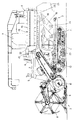
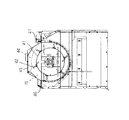
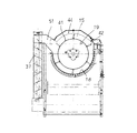
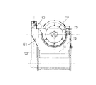
つぎに、図2及び図3に基づき脱穀部4の構成を説明する。なお、図3は、脱穀部4を、後述の排出口38の部分で破断した背面図である。
前記フィードコンベア11に連通した扱室15を脱穀部4の上部に設け、扱室15下方の選別室16内に揺動選別装置17を揺動自在に架設し、扱室15から下方の揺動選別装置17上に脱穀処理物を漏下供給する受網18を張設している。
Below, the structure of the threshing part 4 is demonstrated based on FIG.2 and FIG.3. FIG. 3 is a rear view in which the threshing portion 4 is broken at a portion of a
A
扱室15内に扱胴19を前後方向に架設し、扱胴19の外周面には扱歯42を立設してあり、該扱胴19の駆動回転によって全稈投入された穀稈を扱胴軸芯方向後方に向けて搬送しながら脱穀処理し、脱穀処理後のわら屑などの排稈は扱室終端の排稈口23から機外に排出するように構成してある。
A handling
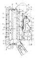
扱胴19は、前部の錐台形状のテーパ部40にスパイラル状の取込みスパイラー22を設け、このテーパ部40に続く円筒状の円筒部41には扱歯42を立設した扱歯取付桟(プレート)43を長手方向に沿って円周等配間隔でボルト39によって取り外し可能に取り付けている。そして、扱胴19は回転軸である扱胴軸19dに取り付けられた円盤状の前側支持部材19a、中間支持部材19b、後側支持部材19cによって支持され、テーパ部40の後端部と円筒部41の前端部が溶接等により連結されている。
The
中間支持部材19bは、受網18の中側板18aの前側近傍に位置している。
中側板18aは、受網18の扱胴軸19dの軸心方向における中間位置(中心位置)に位置する部材であり、一部が受網18よりも扱胴19側に入りこんで、扱室15内の脱穀処理物に移送抵抗を与えるものである。
The intermediate support member 19 b is located in the vicinity of the front side of the middle plate 18 a of the receiving
The middle side plate 18a is a member located at an intermediate position (center position) in the axial center direction of the handling
なお、扱歯取付桟43に立設する扱歯42の長手方向取付ピッチを全て同一にすることもできるが、図2に図示したとおり、扱胴19の軸心方向における扱歯42の間隔が広く設定された第1プレート43aと、この第1プレート43aよりも扱胴19の軸心方向における扱歯42の間隔が狭く設定された第2プレート43bを円周方向で交互に取り付けることで、扱胴19による脱粒効率を高めることができる。また、大豆など脱粒し易い穀物の脱穀作業では、扱胴19から第1プレート43aか、第2プレート43bを取り外したり、第2プレート43bの代わりに第1プレート43aを取り付けるようにすると、脱穀負荷が軽減し脱穀ロスを少なくして、作業能率を高めることができる。
It is possible to make all the mounting pitches in the longitudinal direction of the
また、脱粒しにくい穀物の脱穀作業では、第1プレート43aの代わりに第2プレート43bを取り付けると、脱粒性能を高め、脱穀部4で確実に穀粒を回収して、収量の減少を防止することができる。
In addition, in the threshing operation of grains that are difficult to thresh, if the
また、扱歯42は溶接或いはネジ留めによって扱歯取付桟43に立設するが、回転方向に対して後退角(後退角度)を持たせて立設することで扱歯42に穀稈がつき回りしないようにしている。すなわち、扱歯42の基部側(扱胴19の軸心に近い側)の部位に対して、先端側(扱胴19の軸心に遠い側)が扱胴19の回転方向上手側に偏倚している。
In addition, the tooth-handling 42 is erected on the tooth-
さらに、排出口38に対応する扱胴19の部位における扱歯42の立設後退角(後退角度)を、それよりも前側(フィーダコンペア11側)よりも大きくすることで、脱粒穀稈が停滞しないようにしている。
Furthermore, by setting the standing receding angle (retracting angle) of the tooth handling 42 in the part of the handling
扱室15の上部には、扱歯42の先端回転軌跡に沿うように水平面と傾斜面からなる天板45を、扱胴19を上方から覆う閉状態と開放する開状態とに開閉揺動操作が可能となるように、左側の側縁部を複数のヒンジ46を取付支点として右側の側縁部を複数のボルト47で締め付けている。
At the upper part of the handling
天板45の内面には、扱胴19の回転作動に伴って、扱室15の上部に搬送された脱穀処理物を後方に向けて案内する複数の送塵弁44が、前後方向に所定間隔を隔てて並ぶように固定している。この送塵弁44は、扱室19内の脱穀処理物に後方への移送作用を与える。
On the inner surface of the
前記扱室15の下部に設ける揺動選別装置17の前下方に唐箕20を配備し、揺動選別装置17の前部側下方に1番回収部21を形成し、揺動選別装置17の後部側下方に2番回収部24を形成し、揺動選別装置17の後方に機外排出口25を形成している。
A
揺動選別装置17は、カム式の駆動機構27によって前後方向に揺動駆動されるシーブケース28の上部に、粗選別用のグレンパン29とチャフシーブ30とストローラック31とを、その順にシーブケース28の前側から配備し、シーブケース28の下部に、精選別用のグレンパン32とグレンシーブ33とを、その順にシーブケース28の前側から配備して構成されている。
The
単粒化穀粒や稈屑などが混在する状態で受網18から漏下した選別処理物を、上部のグレンパン29やチャフシーブ30あるいはストローラック31で受け止めて、篩い選別による粗選別処理を施し、かつ、単粒化穀粒や枝梗付き穀粒などが混在する状態でチャフシーブ30から漏下した選別処理物を、下部のグレンパン32やグレンシーブ33で受け止めて、篩い選別による精選別処理を施して、選別処理物を、1番物としての単粒化穀粒を1番回収部21に落とし、2番物としての枝梗付き穀粒や稈屑などの混在物を2番回収部24に落とし、3番物としての稈屑などの塵埃を機外排出口25から機外に排出する。
The sorting processed material leaked from the receiving
唐箕20は、エンジンからの動力で、その回転軸20aを中心に回転駆動されることで選別風を生起し、その選別風が、受網18から漏下した選別処理物や、揺動選別装置17で選別される選別処理物などに向けて供給されることで、選別処理物に対して風力選別処理を施して、選別処理物から比重の小さい稈屑などを吹き分けて、脱穀処理方向下手側の機外排出口25に向けて搬送する。
The
1番回収部21には、唐箕20からの選別風でワラ屑などの塵埃が除去された状態で、揺動選別装置17のグレンシーブ33から漏下した単粒化穀粒を、1番物として回収し、回収した1番物を、その底部に左右向きに配備した1番スクリュー34で、その右端に連通接続した揚送スクリュー35(図4参照)に向けて搬送する。
In the No. 1
揚送スクリュー35は、1番スクリュー34で搬送された1番物を揚送して、袋詰装置の上部に備えたグレンタンク7に供給する(図2及び図4参照)。
2番回収部24には、揺動選別装置17のグレンシーブ33から漏下せずにグレンシーブ33の後端から流下した枝梗付き穀粒や稈屑などの混在物、及び、揺動選別装置17のストローラック31から漏下した枝梗付き穀粒や稈屑などの混在物を2番物として回収し、回収した2番物を、その底部に左右向きに配備した2番スクリュー36で、その右端に連通接続した2番還元スクリュー37(図4参照)に向けて搬送する。
The lifting
In the
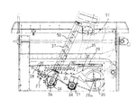
2番還元スクリュー37は、脱穀部4の後部から前部上方に斜めに設けた還元揚穀筒50に内装し、その上端部に前後に広い還元口51を扱室15に向けて開口している。還元口51から扱室15に供給された2番物に対して再び脱穀処理を施す。
The
図7から図9に示す別実施例では、還元口51に扱室15へ導く再脱穀路55と選別室16へ導く再選別路54を設けて、その分岐部に設けるシャッター52を切換レバー53で切り換えることによって2番物の送り先を変更出来るようにしている。再選別路54へ送る2番物は藁屑が少ないもので、受網18の唐箕20上方で、再選別が良く行われるようにしている。
In another embodiment shown in FIG. 7 to FIG. 9, a rethreshing path 55 leading to the handling
機外排出口25は、受網18から漏下せずに排出口38から流下する脱粒穀稈や、篩い選別処理や風力選別処理で揺動選別装置17の後方に選別搬送された稈屑などと共に機外に放出する。
The out-of-
この機外排出口25と前記排出口38を覆って後部カバー48を設け、その内部左側に寄せガイド49を吊り下げて、脱粒穀稈や稈屑等が未刈穀稈に降りかからないようにしている。
A
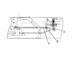
図10は、走行速度を変速する主変速レバー57と副変速レバー58の取付構成を示し、副変速レバー58の水平枢支軸59を軸支部60に枢支すると共に主変速レバー57の取付部61を前記水平枢支軸59に外嵌して、狭い空間に収納している。
FIG. 10 shows a mounting structure of the
図11は、刈取レバー66と脱穀レバー65の取付構成を示し、刈取レバー66の水平軸部66aに脱穀レバー65の回動ブラケット65aを外嵌して、それぞれ刈取切換溝66bと脱穀切換溝65bから突出させている。
FIG. 11 shows a mounting structure of the reaping
4 脱穀部(脱穀装置)
15 扱室
19 扱胴
38 排出口
42 扱歯
43 扱歯取付桟(プレート)
43a 第1プレート
43b 第2プレート
49 ガイド体
4 Threshing unit (threshing device)
15
Claims (4)
該扱胴(19)の外周面には多数の扱歯(42)を立設し、
前記扱室(15)の後部に、排塵物を外部へ排出する排出口(38)を備え、
前記多数の扱歯(42)には、扱胴(19)の軸心に近い基部に対して扱胴(19)の軸心から遠い先端部が扱胴(19)の回転方向上手側に偏倚する後退角度を有し、
前記排出口(38)に臨む扱胴(19)後端部の扱歯(42)の後退角度を、他の扱歯(42)の後退角度よりも大きく設定した脱穀装置。 The handling cylinder (19) is mounted in the handling chamber (15),
A number of teeth (42) are erected on the outer peripheral surface of the cylinder (19),
A discharge port (38) for discharging dust to the outside is provided at the rear of the handling chamber (15),
The plurality of teeth (42) have a distal end that is far from the axis of the handle (19) with respect to the base close to the axis of the handle (19) and is biased toward the upper side in the rotational direction of the handle (19). Has a receding angle to
A threshing apparatus in which the retracting angle of the tooth handling (42) at the rear end of the handling cylinder (19) facing the discharge port (38) is set larger than the retracting angle of the other tooth handling (42).
Priority Applications (1)
| Application Number | Priority Date | Filing Date | Title |
|---|---|---|---|
| JP2012074190A JP2013201964A (en) | 2012-03-28 | 2012-03-28 | Thresher and combine harvester having the thresher |
Applications Claiming Priority (1)
| Application Number | Priority Date | Filing Date | Title |
|---|---|---|---|
| JP2012074190A JP2013201964A (en) | 2012-03-28 | 2012-03-28 | Thresher and combine harvester having the thresher |
Publications (1)
| Publication Number | Publication Date |
|---|---|
| JP2013201964A true JP2013201964A (en) | 2013-10-07 |
Family
ID=49521744
Family Applications (1)
| Application Number | Title | Priority Date | Filing Date |
|---|---|---|---|
| JP2012074190A Pending JP2013201964A (en) | 2012-03-28 | 2012-03-28 | Thresher and combine harvester having the thresher |
Country Status (1)
| Country | Link |
|---|---|
| JP (1) | JP2013201964A (en) |
Cited By (3)
| Publication number | Priority date | Publication date | Assignee | Title |
|---|---|---|---|---|
| JP2015130816A (en) * | 2014-01-10 | 2015-07-23 | 株式会社クボタ | Threshing device |
| CN107278530A (en) * | 2017-07-25 | 2017-10-24 | 李严 | A kind of axial-flow type drum on harvester |
| CN111034474A (en) * | 2019-12-26 | 2020-04-21 | 无为县万祠农机专业合作社 | Corn thresher |
-
2012
- 2012-03-28 JP JP2012074190A patent/JP2013201964A/en active Pending
Cited By (4)
| Publication number | Priority date | Publication date | Assignee | Title |
|---|---|---|---|---|
| JP2015130816A (en) * | 2014-01-10 | 2015-07-23 | 株式会社クボタ | Threshing device |
| CN107278530A (en) * | 2017-07-25 | 2017-10-24 | 李严 | A kind of axial-flow type drum on harvester |
| CN107278530B (en) * | 2017-07-25 | 2023-08-04 | 李严 | Axial flow roller on harvester |
| CN111034474A (en) * | 2019-12-26 | 2020-04-21 | 无为县万祠农机专业合作社 | Corn thresher |
Similar Documents
| Publication | Publication Date | Title |
|---|---|---|
| JP4484779B2 (en) | Handle structure of threshing equipment | |
| JP2010220563A (en) | Normal-type combine harvester | |
| JP6472357B2 (en) | Combine | |
| JP5739709B2 (en) | Threshing device | |
| JP2017176052A (en) | Combine-harvester | |
| JP2013201964A (en) | Thresher and combine harvester having the thresher | |
| JP2010226989A (en) | Threshing structure of combine harvester | |
| JP2009219443A (en) | Whole culm-charging type thresher | |
| JP2015146802A (en) | Threshing device | |
| JP2008237134A (en) | Thresher | |
| JP5174059B2 (en) | Whole grain input combine harvester | |
| JP6016491B2 (en) | Normal combine threshing equipment | |
| JP2010233474A (en) | Combine harvester | |
| JP2008136399A (en) | Thresher | |
| JP2007174999A (en) | Discharged culm-treating structure of whole culm-charging type combine harvester | |
| WO2022260043A1 (en) | Combine | |
| JP7175292B2 (en) | combine | |
| JP5486446B2 (en) | Combined transmission structure | |
| JP5406977B2 (en) | Threshing device for all throwing type combine harvester | |
| JP6013552B2 (en) | Threshing device | |
| JP2006067814A (en) | Recovery apparatus of free grain over rack for thresher | |
| JP2015100339A (en) | Threshing device | |
| JP5797952B2 (en) | Combine handling cylinder | |
| JP2015119667A (en) | Threshing device | |
| JP2020031542A (en) | Combine harvester |