JP2013201832A - Electric power conversion device and work machine - Google Patents

Electric power conversion device and work machine Download PDF

Info

Publication number
JP2013201832A
JP2013201832A JP2012068719A JP2012068719A JP2013201832A JP 2013201832 A JP2013201832 A JP 2013201832A JP 2012068719 A JP2012068719 A JP 2012068719A JP 2012068719 A JP2012068719 A JP 2012068719A JP 2013201832 A JP2013201832 A JP 2013201832A
Authority
JP
Japan
Prior art keywords
power
parallel flow
flow path
upstream
downstream
Prior art date
Legal status (The legal status is an assumption and is not a legal conclusion. Google has not performed a legal analysis and makes no representation as to the accuracy of the status listed.)
Pending
Application number
JP2012068719A
Other languages
Japanese (ja)
Inventor
Sotetsu Yoshida
聡哲 吉田
Current Assignee (The listed assignees may be inaccurate. Google has not performed a legal analysis and makes no representation or warranty as to the accuracy of the list.)
Sumitomo Heavy Industries Ltd
Original Assignee
Sumitomo Heavy Industries Ltd
Priority date (The priority date is an assumption and is not a legal conclusion. Google has not performed a legal analysis and makes no representation as to the accuracy of the date listed.)
Filing date
Publication date
Application filed by Sumitomo Heavy Industries Ltd filed Critical Sumitomo Heavy Industries Ltd
Priority to JP2012068719A priority Critical patent/JP2013201832A/en
Publication of JP2013201832A publication Critical patent/JP2013201832A/en
Pending legal-status Critical Current

Links

Images

Classifications

    • HELECTRICITY
    • H01ELECTRIC ELEMENTS
    • H01LSEMICONDUCTOR DEVICES NOT COVERED BY CLASS H10
    • H01L2924/00Indexing scheme for arrangements or methods for connecting or disconnecting semiconductor or solid-state bodies as covered by H01L24/00
    • H01L2924/0001Technical content checked by a classifier
    • H01L2924/0002Not covered by any one of groups H01L24/00, H01L24/00 and H01L2224/00

Abstract

PROBLEM TO BE SOLVED: To provide an electric power conversion device capable of efficiently cooling a power module without making parallel flow passages thin.SOLUTION: A cooling medium flows in an in-side flow passage from an inlet. A plurality of parallel flow passages which are arrayed in a first direction and allow the cooling medium to flow in a second direction crossing a first direction are connected to the in-side flow passage. Out-side flow passages in which the cooling medium flowing through the parallel flow passages flow into are connected to the parallel flow passages respectively. A power module is thermally coupled to the parallel flow passages. Each of the parallel flow passages includes an upstream-side portion, a downstream-side portion, and a connection portion coupling a downstream end of the upstream-side portion to an upstream end of the downstream-side portion. The upstream-side portion and downstream-side portion are arranged shifting from each other in the first direction.

Description

本発明は、パワーモジュール及び冷却機構を備えた電力変換装置及び作業機械に関する。   The present invention relates to a power conversion device and a work machine including a power module and a cooling mechanism.

ハイブリッド型建設機械に、電動機制御用のインバータや、昇降圧コンバータ等のパワーモジュールが搭載される。U字状に屈曲した1本の冷却流路をパワーモジュールに熱的に結合させることにより、パワーモジュールの冷却が行われる。同一方向に冷却媒体を流す複数の並行流路を用いる構造も公知である。   Power modules such as an inverter for controlling the electric motor and a buck-boost converter are mounted on the hybrid construction machine. The power module is cooled by thermally coupling one cooling channel bent in a U shape to the power module. A structure using a plurality of parallel flow paths for flowing a cooling medium in the same direction is also known.

特開2010−226781号公報JP 2010-226781 A 特開2007−12722号公報JP 2007-12722 A 特開2008−294069号公報JP 2008-294069 A

U字状に屈曲した1本の冷却流路を用いる場合には、冷却流路の上流側と下流側とで、冷却能力に差が生じやすい。パワーモジュールのヒートスポットが、冷却流路の上流側の部分から下流側の部分に偏って取り付けられると、パワーモジュールの冷却が不十分になる場合がある。   When one cooling channel bent in a U-shape is used, a difference in cooling capacity tends to occur between the upstream side and the downstream side of the cooling channel. If the heat spot of the power module is attached to the downstream portion from the upstream portion of the cooling flow path, the power module may be insufficiently cooled.

複数の並行流路で効率的にパワーモジュールを冷却するために、流路の表面近傍の流速を速くすることが好ましい。この要請に応えるためには、並行流路の各々を細くすればよい。ところが、並行流路を細くすると、流路の加工が困難になる。   In order to efficiently cool the power module with a plurality of parallel flow paths, it is preferable to increase the flow velocity near the surface of the flow path. In order to meet this demand, each of the parallel flow paths may be narrowed. However, if the parallel flow paths are narrowed, it becomes difficult to process the flow paths.

本発明の目的は、並行流路を細くすることなく、パワーモジュールを効率的に冷却することができる電力変換装置を提供することである。本発明の他の目的は、この電力変換装置を搭載した作業機械を提供することである。   The objective of this invention is providing the power converter device which can cool a power module efficiently, without narrowing a parallel flow path. Another object of the present invention is to provide a work machine equipped with this power conversion device.

本発明の一観点によると、
流入口から冷却媒体が流入する入側流路と、
前記入側流路に接続され、第1の方向に配列され、各々が前記第1の方向と交差する第2の方向に冷却媒体を流す複数の並行流路と、
前記並行流路の各々に接続され、前記並行流路を流れた冷却媒体が流入する出側流路と、
前記並行流路に熱的に結合するパワーモジュールと
を有し、
前記並行流路の各々は、
上流側部分と、下流側部分と、前記上流側部分の下流端を前記下流側部分の上流端に連結する連結部分とを含み、前記上流側部分と前記下流側部分とは、相互に前記第1の方向にずれて配置されている電力変換装置が提供される。
According to one aspect of the invention,
An inlet-side flow channel into which the cooling medium flows from the inlet,
A plurality of parallel flow paths connected to the inlet flow path and arranged in a first direction, each flowing a cooling medium in a second direction intersecting the first direction;
Connected to each of the parallel flow paths, an outlet flow path into which a cooling medium that has flowed through the parallel flow paths flows, and
A power module thermally coupled to the parallel flow path,
Each of the parallel flow paths
An upstream portion, a downstream portion, and a connecting portion that connects a downstream end of the upstream portion to an upstream end of the downstream portion, wherein the upstream portion and the downstream portion mutually A power conversion device is provided that is displaced in the direction of 1.

上流側部分と下流側部分とが相互に第1の方向にずれているため、上流側部分を流れた
冷却媒体が上流側部分の下流端で流路の壁面に衝突する。これにより、並行流路を細くすることなく、パワーモジュールを効率的に冷却することができる。
Since the upstream portion and the downstream portion are displaced from each other in the first direction, the cooling medium that has flowed through the upstream portion collides with the wall surface of the flow path at the downstream end of the upstream portion. Thereby, a power module can be cooled efficiently, without making a parallel flow path thin.

図1Aは、実施例1による電力変換装置の斜視図であり、図1Bは、実施例による電極変換装置に用いられているコールドプレートの平断面図である。FIG. 1A is a perspective view of the power conversion device according to the first embodiment, and FIG. 1B is a plan sectional view of a cold plate used in the electrode conversion device according to the embodiment. 図2A及び図2Bは、それぞれ図1Bの一点鎖線2A−2A、2B−2Bにおける断面図である。2A and 2B are cross-sectional views taken along one-dot chain lines 2A-2A and 2B-2B in FIG. 1B, respectively. 図3A及び図3Bは、それぞれ実施例1及びその変形例による電力変換装置の断面図である。3A and 3B are cross-sectional views of the power conversion device according to the first embodiment and its modification, respectively. 図4A及び図4Bは、それぞれ実施例1の変形例1及び変形例2による電力変換装置の並行流路の平面図である。4A and 4B are plan views of parallel flow paths of the power conversion device according to Modification 1 and Modification 2 of Embodiment 1, respectively. 図5A、図5B、及び図5Cは、それぞれ実施例1の変形例3、変形例4、及び変形例5による電力変換装置の並行流路の平面図である。5A, FIG. 5B, and FIG. 5C are plan views of parallel flow paths of the power conversion devices according to the third modification, the fourth modification, and the fifth modification, respectively, of the first embodiment. 図6は、実施例1の変形例6による電力変換装置の並行流路の平面図である。FIG. 6 is a plan view of the parallel flow path of the power conversion device according to the sixth modification of the first embodiment. 図7は、実施例2によるショベルの平面図である。FIG. 7 is a plan view of the shovel according to the second embodiment. 図8は、実施例2によるショベルの部分破断側面図である。FIG. 8 is a partially broken side view of the shovel according to the second embodiment. 図9は、実施例2によるショベルのブロック図である。FIG. 9 is a block diagram of an excavator according to the second embodiment. 図10は、実施例3によるフォークリフトの部分破断側面図である。FIG. 10 is a partially broken side view of the forklift according to the third embodiment.

[実施例1]
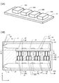
図1Aに、実施例1による電力変換装置の斜視図を示す。コールドプレート10の上に、パワーモジュール50が搭載されている。パワーモジュール50は、例えばパワー素子50A〜50Dを含む。コールドプレート10は、パワーモジュール50に熱的に結合し、パワーモジュール50を冷却する。例えば、パワー素子50A〜50Cは、それぞれ埋込磁石内蔵型(IPM)モータを駆動するためのU相、V相、W相用のインバータ回路である。パワー素子50Dは、例えば蓄電モジュール充放電用の昇降圧コンバータである。パワー素子50A〜50Dは、絶縁ゲートバイポーラトランジスタ(IGBT)等のパワー半導体素子、その駆動回路、及び自己保護回路等を含む。
[Example 1]
FIG. 1A is a perspective view of the power converter according to the first embodiment. A power module 50 is mounted on the cold plate 10. The power module 50 includes, for example, power elements 50A to 50D. The cold plate 10 is thermally coupled to the power module 50 to cool the power module 50. For example, power elements 50A to 50C are U-phase, V-phase, and W-phase inverter circuits for driving an embedded magnet built-in (IPM) motor, respectively. The power element 50D is, for example, a step-up / down converter for charging / discharging the power storage module. Power elements 50A to 50D include a power semiconductor element such as an insulated gate bipolar transistor (IGBT), a driving circuit thereof, a self-protection circuit, and the like.

図1Bに、コールドプレート10の平断面図を示す。コールドプレート10の内部に、冷却媒体を流すための流路が形成されている。以下、流路の構成について説明する。図1Bにおいて、右向きをx軸の正の向きとし、上向きをy軸の正の向きとするxy直交座標系を定義する。   FIG. 1B shows a plan sectional view of the cold plate 10. A flow path for flowing a cooling medium is formed inside the cold plate 10. Hereinafter, the configuration of the flow path will be described. In FIG. 1B, an xy orthogonal coordinate system is defined in which the right direction is the positive direction of the x axis and the upward direction is the positive direction of the y axis.

コールドプレート10のx軸方向負側の縁に、冷却媒体の流入口11及び排出口21が設けられている。流入口11から、x軸の正の向きに、助走路12、テーパ状流路13、及び入側流路14が、この順番に形成されている。助走路12及び入側流路14の幅は一定であり、入側流路14の幅が、助走路12の幅よりも広い。テーパ状流路13の幅は、助走路12から入側流路14に向かって、徐々に広くなっている。流入口11から助走路12に流入した冷却媒介が、テーパ状流路13を経由して入側流路14に流入する。入側流路14は、x軸方向に長い平面形状を有し、x軸の正の向きに冷却媒体を流す。   A cooling medium inflow port 11 and a discharge port 21 are provided at the edge on the negative side in the x-axis direction of the cold plate 10. From the inflow port 11, a runway 12, a tapered channel 13, and an inlet channel 14 are formed in this order in the positive direction of the x axis. The width of the approach path 12 and the inlet-side channel 14 is constant, and the width of the inlet-side channel 14 is wider than the width of the approach path 12. The width of the tapered channel 13 gradually increases from the runway 12 toward the inlet channel 14. The cooling medium that has flowed into the runway 12 from the inflow port 11 flows into the inlet-side flow path 14 via the tapered flow path 13. The inlet channel 14 has a planar shape that is long in the x-axis direction, and allows the cooling medium to flow in the positive direction of the x-axis.

y軸方向に長い複数の並行流路17が、x軸方向に配列している。並行流路17は、パワー素子50A〜50Dごとに配備されている。並行流路17の上流端が、入側均等化構造物22を介して入側流路14に接続されている。入側流路14内を流れる冷却媒体が、入側均等化構造物22を経由して、並行流路17の各々に流入する。並行流路17の各々は、入側流路14から流入した冷却媒体を、y軸の負の向きに流す。   A plurality of parallel flow paths 17 that are long in the y-axis direction are arranged in the x-axis direction. The parallel flow path 17 is disposed for each of the power elements 50A to 50D. The upstream end of the parallel flow path 17 is connected to the input side flow path 14 via the input side equalization structure 22. The cooling medium flowing in the inlet-side channel 14 flows into each of the parallel channels 17 via the inlet-side equalization structure 22. Each of the parallel flow paths 17 causes the cooling medium flowing in from the input flow path 14 to flow in the negative y-axis direction.

並行流路17の各々の下流端が、出側均等化構造物23を介して出側流路20に接続されている。並行流路17を流れた冷却媒体が、出側均等化構造物23を経由して、出側流路20に流入する。   Each downstream end of the parallel flow path 17 is connected to the output side flow path 20 via the output side equalization structure 23. The cooling medium flowing through the parallel flow path 17 flows into the output side flow path 20 via the output side equalizing structure 23.

出側流路20は、x軸方向に長い平面形状を有し、そのx軸方向負側の端部が、排出口21となる。並行流路17から出側流路20に流入した冷却媒体は、x軸の負の向きに流れ、排出口21から、コールドプレート10の外部に排出される。   The outlet-side channel 20 has a planar shape that is long in the x-axis direction, and the end on the negative side in the x-axis direction becomes the discharge port 21. The cooling medium that has flowed into the outlet-side channel 20 from the parallel channel 17 flows in the negative direction of the x axis, and is discharged from the discharge port 21 to the outside of the cold plate 10.

入側均等化構造物22は、入側緩衝室15と、複数の入側流通孔16とを含む。入側緩衝室15は、x軸方向に長い平面形状を有し、入側流路14の側方に、入側流路14と平行に配置されている。並行流路17の上流端が、入側緩衝室15に接続されている。すなわち、並行流路15の上流端が、入側緩衝室15によって相互に接続されている。   The entry-side equalization structure 22 includes an entry-side buffer chamber 15 and a plurality of entry-side circulation holes 16. The entry-side buffer chamber 15 has a planar shape that is long in the x-axis direction, and is disposed on the side of the entry-side passage 14 in parallel with the entry-side passage 14. The upstream end of the parallel flow path 17 is connected to the entry-side buffer chamber 15. That is, the upstream ends of the parallel flow paths 15 are connected to each other by the entry-side buffer chamber 15.

入側流通孔16は、x軸方向に離散的に分布し、入側流路14と入側緩衝室15とを接続する。入側流路14の相対的に下流側に配置される入側流通孔16の流路断面が、相対的に上流側に配置される入側流通孔16の流路断面より大きい。具体的には、x軸の正の側に位置する入側流通孔16ほど、x軸方向の寸法が大きくされている。   The inlet-side circulation holes 16 are discretely distributed in the x-axis direction and connect the inlet-side flow path 14 and the inlet-side buffer chamber 15. The channel cross section of the inlet-side circulation hole 16 disposed relatively downstream of the inlet-side channel 14 is larger than the channel cross-section of the inlet-side circulation hole 16 disposed relatively upstream. Specifically, the dimension in the x-axis direction is made larger as the inlet-side circulation hole 16 located on the positive side of the x-axis.

出側均等化構造物23は、出側緩衝室18と、複数の出側流通孔19とを含む。出側均等化構造物23の平面形状は、入側均等化構造物22の平面形状と線対称である。入側流路14、入側緩衝室15、入側流通孔16、出側流路20、出側緩衝室18、及び出側流通孔19の流路断面は長方形であり、並行流路17の流路断面は円形である。   The exit side equalizing structure 23 includes an exit side buffer chamber 18 and a plurality of exit side circulation holes 19. The planar shape of the outlet side equalizing structure 23 is line symmetric with the planar shape of the inlet side equalizing structure 22. The cross sections of the inlet side flow path 14, the inlet side buffer chamber 15, the inlet side flow hole 16, the outlet side flow path 20, the outlet side buffer chamber 18, and the outlet side flow hole 19 are rectangular. The channel cross section is circular.

並行流路17の各々は、2本の上流側部分17A、連結部分17B、及び3本の下流側部分17Cを含む。上流側部分17Aの上流端が入側緩衝室15に接続されている。下流側部分17Cの下流端が出側緩衝室18に接続されている。上流側部分17Aと下流側部分17Cとは、x方向にずれて配置されている。連結部分17Bは、上流側部分17Aの下流端を下流側部分17Cの上流端に連結する。上流側部分17Aと連結部分17Bとのなす角度、及び連結部分17Bと下流側部分17Cとのなす角度は、ほぼ直角である。   Each of the parallel flow paths 17 includes two upstream portions 17A, a connecting portion 17B, and three downstream portions 17C. The upstream end of the upstream portion 17 </ b> A is connected to the entrance buffer chamber 15. The downstream end of the downstream portion 17 </ b> C is connected to the outlet buffer chamber 18. The upstream portion 17A and the downstream portion 17C are arranged so as to be shifted in the x direction. The connecting portion 17B connects the downstream end of the upstream portion 17A to the upstream end of the downstream portion 17C. The angle formed by the upstream portion 17A and the connecting portion 17B and the angle formed by the connecting portion 17B and the downstream portion 17C are substantially perpendicular.

上流側部分10Aと連結部分17Bとの接続点は、xy面内に関してパワー素子50A〜50Dのいずれかと重なる。パワーモジュール50A〜50Dは、並行流路17と熱的に結合している。並行流路17を流れる冷却媒体によって、パワーモジュール50A〜50Dを効率的に冷却することができる。   A connection point between the upstream portion 10A and the connecting portion 17B overlaps any of the power elements 50A to 50D in the xy plane. The power modules 50 </ b> A to 50 </ b> D are thermally coupled to the parallel flow path 17. The power modules 50 </ b> A to 50 </ b> D can be efficiently cooled by the cooling medium flowing through the parallel flow path 17.

入側均等化構造物22及び出側均等化構造物23は、x方向に並ぶ複数の並行流路17を流れる冷却媒体の流量を均等化する。なお、流量の高精度な均等化が要求されない場合には、入側均等化構造物22及び出側均等化構造物23を省略し、並行流路17を入側流路14及び出側流路20に直接接続してもよい。   The inlet side equalizing structure 22 and the outlet side equalizing structure 23 equalize the flow rate of the cooling medium flowing through the plurality of parallel flow paths 17 arranged in the x direction. In addition, when high-precision equalization of the flow rate is not required, the input-side equalization structure 22 and the output-side equalization structure 23 are omitted, and the parallel flow path 17 is replaced with the input-side flow path 14 and the output-side flow path. 20 may be connected directly.

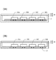
図2Aに、図1Bの一点鎖線2A−2Aにおける断面図を示す。コールドプレート10内に、入側緩衝室15、並行流路17、及び出側流路20が形成されている。コールドプレート10の厚さは、例えば25mmである。入側緩衝室15及び出側流路20の高さ(厚さ方向の寸法)は、例えば15mmである。並行流路17の各々の直径Dは、例えば3mmである。図1Bに示した入側流路14、入側流通孔16、出側緩衝室18、出側流通孔19の高さは、入側緩衝室15の高さと同一である。   2A is a cross-sectional view taken along one-dot chain line 2A-2A in FIG. 1B. In the cold plate 10, an inlet buffer chamber 15, a parallel channel 17, and an outlet channel 20 are formed. The thickness of the cold plate 10 is 25 mm, for example. The height (dimension in the thickness direction) of the inlet buffer chamber 15 and the outlet channel 20 is, for example, 15 mm. The diameter D of each parallel flow path 17 is 3 mm, for example. The heights of the inlet-side flow path 14, the inlet-side circulation hole 16, the outlet-side buffer chamber 18, and the outlet-side circulation hole 19 shown in FIG. 1B are the same as the height of the inlet-side buffer chamber 15.

図2Bに、図1Bの一点鎖線2B−2Bにおける断面図を示す。コールドプレート10内に、入側流路14、入側緩衝室15、並行流路17の下流側部分17C、出側緩衝室18、及び出側流路20が形成されている。入側流通孔16、出側流通孔19及び並行流路
17の上流側部分17A(図1B)は、この断面図に現れていない。
2B is a cross-sectional view taken along one-dot chain line 2B-2B in FIG. 1B. In the cold plate 10, an inlet-side channel 14, an inlet-side buffer chamber 15, a downstream portion 17 </ b> C of the parallel channel 17, an outlet-side buffer chamber 18, and an outlet-side channel 20 are formed. The inlet-side circulation hole 16, the outlet-side circulation hole 19 and the upstream portion 17A (FIG. 1B) of the parallel flow path 17 do not appear in this cross-sectional view.

上述のコールドプレート10は、例えば鋳造法により作製することができる。コールドプレート10には、例えばアルミニウムを用いることができる。   The above-mentioned cold plate 10 can be produced by a casting method, for example. For the cold plate 10, for example, aluminum can be used.

図3Aに、実施例1による電力変換装置の断面図を示す。コールドプレート10及びパワーモジュール50の構成は、図1Aに示した構成と同一である。コールドプレート10及びパワーモジュール50が、筐体30内に収容されている。筐体30は、底面、及び底面の外周部から立ち上がった側面を有する筐体下部30A、及び筐体下部30Aの開口部を塞ぐ上蓋30Bを有する。コールドプレート10は、筐体下部30Aの底面に固定されている。   FIG. 3A shows a cross-sectional view of the power converter according to the first embodiment. The configurations of the cold plate 10 and the power module 50 are the same as those shown in FIG. 1A. The cold plate 10 and the power module 50 are accommodated in the housing 30. The housing 30 includes a housing lower portion 30A having a bottom surface and a side surface rising from an outer peripheral portion of the bottom surface, and an upper lid 30B that closes an opening of the housing lower portion 30A. The cold plate 10 is fixed to the bottom surface of the housing lower part 30A.

図3Bに、実施例1の変形例による電力変換装置の断面図を示す。この変形例では、筐体下部30Aの底面内に、冷却流路が形成されている。すなわち、筐体下部30Aの底面がコールドプレート10を兼ねている。このような構成にすることにより、部品点数を削減することができる。   FIG. 3B shows a cross-sectional view of a power conversion device according to a modification of the first embodiment. In this modification, a cooling flow path is formed in the bottom surface of the housing lower part 30A. That is, the bottom surface of the housing lower part 30 </ b> A also serves as the cold plate 10. With this configuration, the number of parts can be reduced.

上記実施例1及びその変形例においては、並行流路17の上流側部分17Aを流れた冷却媒体が、その下流端において並行流路17の壁面に衝突する。この衝突により、コールドプレート10から冷却媒体への熱伝達効率を高めることができる。これにより、パワーモジュール50を効率的に冷却することができる。   In the first embodiment and the modification thereof, the cooling medium that has flowed through the upstream portion 17A of the parallel flow path 17 collides with the wall surface of the parallel flow path 17 at the downstream end. By this collision, the heat transfer efficiency from the cold plate 10 to the cooling medium can be increased. Thereby, the power module 50 can be cooled efficiently.

上記実施例1においては、2本の上流側部分17Aに対して3本の下流側部分17Cが接続されている。下流側部分17Cの本数が、上流側部分17Aの本数より多いため、下流側部分17Cの流路抵抗が、上流側部分17Aの流路抵抗より低いこのため、並行流路17内に冷却媒体の滞留が生じにくい。このように、上流側部分17Aの流路断面積と下流側部分17Cの流路断面積とを等しくする場合には、下流側部分17Cの本数を上流側部分17Aの本数より多くすることが好ましい。   In the first embodiment, three downstream portions 17C are connected to the two upstream portions 17A. Since the number of the downstream portions 17C is larger than the number of the upstream portions 17A, the flow resistance of the downstream portion 17C is lower than the flow resistance of the upstream portion 17A. Stagnation hardly occurs. Thus, when making the channel cross-sectional area of the upstream portion 17A and the channel cross-sectional area of the downstream portion 17C equal, it is preferable that the number of the downstream portions 17C is larger than the number of the upstream portions 17A. .

図4Aに、実施例1の変形例1による電力変換装置の並行流路17の平面形状を示す。変形例1においては、並行流路17の各々が、1本の上流側部分17A、2本の下流側部分17C、及び上流側部分17Aと下流側部分17Cとを連結する連結流路17Bとで構成される。上流側部分17A、下流側部分17C、及び連結流路17Bの流路断面積はすべて等しい。このため、下流側部分17Cの流路断面積の合計は、上流側部分17Aの流路断面積の合計よりも大きくなる。これにより、並行流路17内での冷却媒体の滞留を防止することができる。   FIG. 4A shows a planar shape of the parallel flow path 17 of the power conversion device according to the first modification of the first embodiment. In the first modification, each of the parallel flow channels 17 includes one upstream portion 17A, two downstream portions 17C, and a connection flow channel 17B that connects the upstream portion 17A and the downstream portion 17C. Composed. The cross-sectional areas of the upstream portion 17A, the downstream portion 17C, and the connecting flow channel 17B are all equal. For this reason, the total of the cross-sectional area of the downstream portion 17C is larger than the total of the cross-sectional areas of the upstream portion 17A. Thereby, the retention of the cooling medium in the parallel flow path 17 can be prevented.

図4Bに、実施例1の変形例2による電力変換装置の並行流路17の平面形状を示す。変形例2においては、パワー素子50A〜50Dごとに、3本の上流側部分17Aと3本の下流側部分17Cが配備されている。1本の上流側部分17Aが、連結部分17Bにより1本の下流側部分17Cに連結されている。上流側部分17Aは、相互に連結されていない。上流側部分17Aと連結部分17Bとのなす角度、及び連結部分17Bと下流側部分17Cとのなす角度は、ほぼ直角である。実施例1及びその変形例1では、上流側部分17Aと連結部分17Bとの接続箇所で流路が分岐していた。変形例2では、流路を分岐させることに代えて、折れ曲がり部分を設けている。この折れ曲がり部分で、冷却媒体が流路の壁面に衝突する。   The planar shape of the parallel flow path 17 of the power converter device by the modification 2 of Example 1 is shown to FIG. 4B. In the modified example 2, three upstream portions 17A and three downstream portions 17C are provided for each of the power elements 50A to 50D. One upstream portion 17A is connected to one downstream portion 17C by a connecting portion 17B. The upstream portions 17A are not connected to each other. The angle formed by the upstream portion 17A and the connecting portion 17B and the angle formed by the connecting portion 17B and the downstream portion 17C are substantially perpendicular. In Example 1 and its modification example 1, the flow path was branched at the connection point between the upstream portion 17A and the connecting portion 17B. In the modified example 2, instead of branching the flow path, a bent portion is provided. At this bent portion, the cooling medium collides with the wall surface of the flow path.

図5Aに、実施例1の変形例3による電力変換装置の並行流路17の平面形状を示す。変形例3においては、並行流路17の各々の上流側部分17Aと下流側部分17Cとが、2本ずつ配置されている。連結部分17Bが、2本の上流側部分17Aの下流端を、2本
の下流側部分17Cの上流端に連結する。2本の下流側部分17Cのうち1本は、x方向に関して2本の上流側部分17Aの間に配置される。上流側部分17Aの間に配置された下流側部分17Cの流路断面は、上流側部分17Aの流路断面よりも大きい。このため、並行流路17内での冷却媒体の滞留を防止することができる。このように、下流側部分17Cの流路断面積の合計を、上流側部分17Aの流路断面積の合計よりも大きくすることが好ましい。
The planar shape of the parallel flow path 17 of the power converter device by the modification 3 of Example 1 is shown to FIG. 5A. In the third modification, two upstream portions 17A and two downstream portions 17C of the parallel flow path 17 are arranged. The connecting portion 17B connects the downstream ends of the two upstream portions 17A to the upstream ends of the two downstream portions 17C. One of the two downstream portions 17C is disposed between the two upstream portions 17A in the x direction. The channel cross section of the downstream portion 17C disposed between the upstream portions 17A is larger than the channel cross section of the upstream portion 17A. For this reason, the retention of the cooling medium in the parallel flow path 17 can be prevented. Thus, it is preferable to make the sum total of the channel cross-sectional areas of the downstream portion 17C larger than the sum of the channel cross-sectional areas of the upstream portion 17A.

図5Bに、実施例1の変形例4による電力変換装置の並行流路17の平面形状を示す。変形例4においては、並行流路17の各々は、2本の上流側部分17Aと1本の下流側部分17Cとを含む。1本の下流側部分17Cは、x方向に関して、2本の上流側部分17Aの間に配置されている。連結部分17Bが、2本の上流側部分17Aの下流端を、1本の下流側部分17Cの上流端に連結している。   The planar shape of the parallel flow path 17 of the power converter device by the modification 4 of Example 1 is shown to FIG. 5B. In the modified example 4, each of the parallel flow paths 17 includes two upstream portions 17A and one downstream portion 17C. One downstream portion 17C is disposed between the two upstream portions 17A in the x direction. The connecting portion 17B connects the downstream ends of the two upstream portions 17A to the upstream ends of the single downstream portion 17C.

下流側部分17Cの流路断面積は、上流側部分17Aの各々の流路断面積の2倍以上である。このため、並行流路17内での冷却媒体の滞留を防止することができる。また、滞留を防止する効果を高めるために、下流側部分17Cの流路断面積を、上流側部分17Aの流路断面積の合計より大きくすることが好ましい。   The channel cross-sectional area of the downstream portion 17C is at least twice the channel cross-sectional area of each of the upstream portions 17A. For this reason, the retention of the cooling medium in the parallel flow path 17 can be prevented. Further, in order to enhance the effect of preventing the stay, it is preferable that the flow passage cross-sectional area of the downstream portion 17C is larger than the total flow passage cross-sectional area of the upstream portion 17A.

図5Cに、実施例1の変形例5による電力変換装置の並行流路17の平面形状を示す。変形例5においては、並行流路17の各々は、3本の上流側部分17Aと2本の下流側部分17Cとを含む。下流側部分17Cは、x方向に関して、相互に隣り合う2本の上流側部分17Aの間に配置されている。連結部分17Bが、3本の上流側部分17Aの下流端を、2本の下流側部分17Cの上流端に連結している。下流側部分17Cの流路断面積の合計は、上流側部分17Aの流路断面積の合計より大きい。このため、並行流路17内での冷却媒体の滞留を防止することができる。   The planar shape of the parallel flow path 17 of the power converter device by the modification 5 of Example 1 is shown to FIG. 5C. In Modification 5, each of the parallel flow paths 17 includes three upstream portions 17A and two downstream portions 17C. The downstream portion 17C is disposed between two upstream portions 17A adjacent to each other in the x direction. The connecting portion 17B connects the downstream ends of the three upstream portions 17A to the upstream ends of the two downstream portions 17C. The sum of the cross-sectional areas of the downstream portion 17C is larger than the sum of the cross-sectional areas of the upstream portion 17A. For this reason, the retention of the cooling medium in the parallel flow path 17 can be prevented.

図6に、実施例1の変形例6による電力変換装置の並行流路17の平面形状を示す。実施例1、及びその変形例1〜変形例5では、並行流路7の上流側部分17Aと連結部分17Bとのなす角度がほぼ直角であった。変形例6では、上流側部分17Aと連結部分17Bとのなす角度が90°より大きい。すなわち、連結部分17Bは、x方向に対して斜めの方向に伸びる。変形例6においても、上流側部分17Aと連結部分17Bとの接続箇所で、冷却媒体が流路の壁面に衝突するため、コールドプレート10(図1B)から冷却媒体への熱伝達効率を高めることができる。   In FIG. 6, the planar shape of the parallel flow path 17 of the power converter device by the modification 6 of Example 1 is shown. In Example 1 and its modifications 1 to 5, the angle formed by the upstream portion 17A and the connecting portion 17B of the parallel flow path 7 was substantially a right angle. In Modification 6, the angle formed by the upstream portion 17A and the connecting portion 17B is greater than 90 °. That is, the connecting portion 17B extends in an oblique direction with respect to the x direction. Also in the modified example 6, since the cooling medium collides with the wall surface of the flow path at the connection portion between the upstream portion 17A and the connecting portion 17B, the heat transfer efficiency from the cold plate 10 (FIG. 1B) to the cooling medium is increased. Can do.

上述のように、実施例1及びその変形例においては、並行流路17の各々の上流側部分17A及び下流側部分17Cの一方は、少なくとも2本配備されている。並行流路17の各々の上流側部分17A及び下流側部分17Cの一方を、少なくとも2本配備することにより、パワー素子50A〜50Dを効率的に冷却することができる。   As described above, in the first embodiment and the modifications thereof, at least two of the upstream portion 17A and the downstream portion 17C of each parallel flow path 17 are provided. By disposing at least two of the upstream portion 17A and the downstream portion 17C of each parallel flow path 17, the power elements 50A to 50D can be efficiently cooled.

[実施例2]
図7に、実施例2による作業機械の例としてショベルの平面図を示す。下部走行体71に、旋回軸受け73を介して、上部旋回体70が取り付けられている。上部旋回体70に、エンジン74、メインポンプ75、旋回用電動モータ(電動機)76、油タンク77、冷却ファン78、座席79、蓄電モジュール80、電動発電機83、電動発電機用インバータ90、旋回用インバータ91、及び蓄電器用昇降圧コンバータ92が搭載されている。エンジン74は、燃料の燃焼により動力を発生する。エンジン74、メインポンプ75、及び電動発電機83が、トルク伝達機構81を介して相互にトルクの送受を行う。メインポンプ75は、ブーム82等の油圧シリンダに圧油を供給する。
[Example 2]
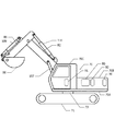
FIG. 7 is a plan view of an excavator as an example of the work machine according to the second embodiment. An upper swing body 70 is attached to the lower traveling body 71 via a swing bearing 73. The upper turning body 70 includes an engine 74, a main pump 75, a turning electric motor (electric motor) 76, an oil tank 77, a cooling fan 78, a seat 79, a power storage module 80, a motor generator 83, a motor generator inverter 90, a turning. The inverter 91 and the capacitor buck-boost converter 92 are mounted. The engine 74 generates power by burning fuel. The engine 74, the main pump 75, and the motor generator 83 transmit and receive torque to and from each other via the torque transmission mechanism 81. The main pump 75 supplies pressure oil to a hydraulic cylinder such as the boom 82.

電動発電機83は、エンジン74の動力によって駆動され、発電を行う(発電運転)。
発電された電力は、蓄電モジュール80に供給され、蓄電モジュール80が充電される。また、電動発電機83は、蓄電モジュール80からの電力によって駆動され、エンジン74をアシストするための動力を発生する(アシスト運転)。油タンク77は、油圧回路の油を貯蔵する。冷却ファン78は、油圧回路の油温の上昇を抑制する。操作者は、座席79に着座して、ハイブリッド型ショベルを操作する。
The motor generator 83 is driven by the power of the engine 74 to generate power (power generation operation).
The generated power is supplied to the power storage module 80, and the power storage module 80 is charged. In addition, the motor generator 83 is driven by the electric power from the power storage module 80 and generates power for assisting the engine 74 (assist operation). The oil tank 77 stores oil of the hydraulic circuit. The cooling fan 78 suppresses an increase in the oil temperature of the hydraulic circuit. The operator sits on the seat 79 and operates the hybrid excavator.

図8に、実施例2によるショベルの部分破断側面図を示す。下部走行体71に、旋回軸受け73を介して上部旋回体70が搭載されている。上部旋回体70は、旋回フレーム70A、カバー70B、及びキャビン70Cを含む。旋回フレーム70Aは、キャビン70C、及び種々の部品の支持構造体として機能する。カバー70Bは、支持構造体70Aに搭載された種々の部品、例えば蓄電モジュール80、電動発電機用インバータ90、旋回用インバータ91、蓄電器用昇降圧コンバータ92等を覆う。キャビン70C内に座席79(図7)が収容されている。   In FIG. 8, the partially broken side view of the shovel by Example 2 is shown. An upper swing body 70 is mounted on the lower traveling body 71 via a swing bearing 73. The upper swing body 70 includes a swing frame 70A, a cover 70B, and a cabin 70C. The swivel frame 70A functions as a support structure for the cabin 70C and various components. The cover 70B covers various components mounted on the support structure 70A, for example, the power storage module 80, the motor generator inverter 90, the turning inverter 91, the battery step-up / down converter 92, and the like. A seat 79 (FIG. 7) is accommodated in the cabin 70C.

旋回用電動モータ76(図7)が、その駆動対象である旋回フレーム70Aを、下部走行体71に対して、時計回り、または反時計周りに旋回させる。上部旋回体70に、ブーム82が取り付けられている。ブーム82は、油圧駆動されるブームシリンダ107により、上部旋回体70に対して上下方向に揺動する。ブーム82の先端に、アーム85が取り付けられている。アーム85は、油圧駆動されるアームシリンダ108により、ブーム82に対して前後方向に揺動する。アーム85の先端にバケット86が取り付けられている。バケット86は、油圧駆動されるバケットシリンダ109により、アーム85に対して揺動する。   The turning electric motor 76 (FIG. 7) turns the turning frame 70 </ b> A to be driven, clockwise or counterclockwise with respect to the lower traveling body 71. A boom 82 is attached to the upper swing body 70. The boom 82 swings up and down with respect to the upper swing body 70 by a hydraulically driven boom cylinder 107. An arm 85 is attached to the tip of the boom 82. The arm 85 swings in the front-rear direction with respect to the boom 82 by an arm cylinder 108 that is hydraulically driven. A bucket 86 is attached to the tip of the arm 85. The bucket 86 swings with respect to the arm 85 by a hydraulically driven bucket cylinder 109.

図9に、実施例2によるショベルのブロック図を示す。図9において、機械的動力系を二重線で表し、高圧油圧ラインを太い実線で表し、パイロットラインを破線で表す。   FIG. 9 shows a block diagram of an excavator according to the second embodiment. In FIG. 9, the mechanical power system is represented by a double line, the high-pressure hydraulic line is represented by a thick solid line, and the pilot line is represented by a broken line.

エンジン74の駆動軸がトルク伝達機構81の入力軸に連結されている。エンジン74には、電気以外の燃料によって駆動力を発生するエンジン、例えばディーゼルエンジン等の内燃機関が用いられる。エンジン74は、作業機械の運転中は、常時駆動されている。   The drive shaft of the engine 74 is connected to the input shaft of the torque transmission mechanism 81. As the engine 74, an engine that generates a driving force by a fuel other than electricity, for example, an internal combustion engine such as a diesel engine is used. The engine 74 is always driven during operation of the work machine.

電動発電機83の駆動軸が、トルク伝達機構81の他の入力軸に連結されている。電動発電機83は、電動(アシスト)運転と、発電運転との双方の運転動作を行うことができる。電動発電機83には、例えば磁石がロータ内部に埋め込まれた内部磁石埋込型(IPM)モータが用いられる。   The drive shaft of the motor generator 83 is connected to the other input shaft of the torque transmission mechanism 81. The motor generator 83 can perform both the electric (assist) operation and the power generation operation. As the motor generator 83, for example, an internal magnet embedded (IPM) motor in which magnets are embedded in the rotor is used.

トルク伝達機構81は、2つの入力軸と1つの出力軸とを有する。この出力軸には、メインポンプ75の駆動軸が連結されている。   The torque transmission mechanism 81 has two input shafts and one output shaft. The output shaft is connected to the drive shaft of the main pump 75.

エンジン74に加わる負荷が大きい場合には、電動発電機83がアシスト運転を行い、電動発電機83の駆動力がトルク伝達機構81を介してメインポンプ75に伝達される。これにより、エンジン74に加わる負荷が軽減される。一方、エンジン74に加わる負荷が小さい場合には、エンジン74の駆動力がトルク伝達機構81を介して電動発電機83に伝達されることにより、電動発電機83が発電運転される。電動発電機83をアシスト運転するときには、インバータ90から電動発電機83に三相交流電力が供給される。電動発電機83が発電運転されているときには、電動発電機83からインバータ90に三相交流電力が供給される。インバータ90は、制御装置130により制御される。   When the load applied to the engine 74 is large, the motor generator 83 performs an assist operation, and the driving force of the motor generator 83 is transmitted to the main pump 75 via the torque transmission mechanism 81. Thereby, the load applied to the engine 74 is reduced. On the other hand, when the load applied to the engine 74 is small, the driving force of the engine 74 is transmitted to the motor generator 83 via the torque transmission mechanism 81, so that the motor generator 83 is in a power generation operation. When assisting the motor generator 83, three-phase AC power is supplied from the inverter 90 to the motor generator 83. When the motor generator 83 is in a power generation operation, three-phase AC power is supplied from the motor generator 83 to the inverter 90. The inverter 90 is controlled by the control device 130.

制御装置130は、中央処理装置(CPU)130A及び内部メモリ130Bを含む。CPU130Aは、内部メモリ130Bに格納されている駆動制御用プログラムを実行する。制御装置130は、表示装置135に、各種装置の劣化状態等を表示することにより
、運転者の注意を喚起する。
The control device 130 includes a central processing unit (CPU) 130A and an internal memory 130B. The CPU 130A executes a drive control program stored in the internal memory 130B. The control device 130 alerts the driver by displaying the deterioration state of various devices on the display device 135.

メインポンプ75は、高圧油圧ライン116を介して、コントロールバルブ117に油圧を供給する。コントロールバルブ117は、運転者からの指令により、油圧モータ101A、101B、ブームシリンダ107、アームシリンダ108、及びバケットシリンダ109に油圧を分配する。油圧モータ101A及び101Bは、それぞれ図8に示した下部走行体71に備えられた左右の2本のクローラを駆動する。   The main pump 75 supplies hydraulic pressure to the control valve 117 via the high pressure hydraulic line 116. The control valve 117 distributes hydraulic pressure to the hydraulic motors 101A and 101B, the boom cylinder 107, the arm cylinder 108, and the bucket cylinder 109 in accordance with a command from the driver. The hydraulic motors 101A and 101B drive two left and right crawlers provided in the lower traveling body 71 shown in FIG.

電動発電機83の電気系統の入出力端子が、インバータ90を介して蓄電回路190に接続されている。蓄電回路190は、蓄電モジュール80(図7、図8)及び蓄電器用昇降圧コンバータ92(図8)を含む。インバータ90は、制御装置130からの指令に基づき、電動発電機83から供給された三相交流電力を直流電力に変換して、蓄電回路190に供給する。または、蓄電回路190から供給された直流電力を三相交流電力に変換して、電動発電機83に供給する。蓄電回路190には、さらに、旋回用インバータ91を介して旋回モータ76が接続されている。蓄電回路190及び旋回用インバータ91は、制御装置130により制御される。   An input / output terminal of the electric system of the motor generator 83 is connected to the power storage circuit 190 via the inverter 90. The power storage circuit 190 includes a power storage module 80 (FIGS. 7 and 8) and a capacitor buck-boost converter 92 (FIG. 8). The inverter 90 converts the three-phase AC power supplied from the motor generator 83 into DC power based on a command from the control device 130 and supplies the DC power to the power storage circuit 190. Alternatively, the DC power supplied from the storage circuit 190 is converted into three-phase AC power and supplied to the motor generator 83. Further, a turning motor 76 is connected to the storage circuit 190 via a turning inverter 91. The storage circuit 190 and the turning inverter 91 are controlled by the control device 130.

旋回モータ76は、旋回用インバータ91により交流駆動され、力行動作及び回生動作の双方の運転を行うことができる。旋回モータ76には、例えばIPMモータが用いられる。IPMモータは、回生時に大きな誘導起電力を発生する。力行動作時には、インバータ91が、蓄電回路190から供給される直流電力を三相交流電力に変換して、旋回モータ76に供給する。回生動作時には、インバータ91が、旋回モータ76から供給される三相交流電力を直流電力に変換して、蓄電回路190に供給する。   The turning motor 76 is AC driven by the turning inverter 91 and can perform both a power running operation and a regenerative operation. As the turning motor 76, for example, an IPM motor is used. An IPM motor generates a large induced electromotive force during regeneration. During the power running operation, the inverter 91 converts the DC power supplied from the power storage circuit 190 into three-phase AC power and supplies it to the turning motor 76. During the regenerative operation, the inverter 91 converts the three-phase AC power supplied from the turning motor 76 into DC power and supplies it to the power storage circuit 190.

旋回モータ76の力行動作中は、旋回モータ76が、減速機124を介して、上部旋回体70を旋回させる。この際、減速機124は、回転速度を遅くする。これにより、旋回モータ76で発生した回転力が増大する。また、回生運転時には、上部旋回体70の回転運動が、減速機124を介して旋回モータ76に伝達されることにより、旋回モータ76が回生電力を発生する。この際、減速機124は、力行運転の時とは逆に、回転速度を速める。これにより、旋回モータ76の回転数を上昇させることができる。   During the power running operation of the swing motor 76, the swing motor 76 rotates the upper swing body 70 via the speed reducer 124. At this time, the speed reducer 124 decreases the rotation speed. As a result, the rotational force generated by the turning motor 76 increases. Further, during regenerative operation, the rotational motion of the upper swing body 70 is transmitted to the swing motor 76 via the speed reducer 124, whereby the swing motor 76 generates regenerative power. At this time, the speed reducer 124 increases the rotation speed, contrary to the power running operation. Thereby, the rotation speed of the turning motor 76 can be increased.

レゾルバ122が、旋回モータ76の回転軸の回転方向の位置を検出する。検出結果は、制御装置130に入力される。旋回モータ76の運転前と運転後における回転軸の回転方向の位置を検出することにより、旋回角度及び旋回方向が導出される。   The resolver 122 detects the position of the rotation shaft of the turning motor 76 in the rotation direction. The detection result is input to the control device 130. By detecting the position of the rotating shaft in the rotational direction before and after the operation of the turning motor 76, the turning angle and the turning direction are derived.

メカニカルブレーキ123が、旋回モータ76の回転軸に連結されており、機械的な制動力を発生する。メカニカルブレーキ123の制動状態と解除状態とは、制御装置130からの制御を受け、電磁的スイッチにより切り替えられる。   A mechanical brake 123 is connected to the rotating shaft of the turning motor 76 and generates a mechanical braking force. The braking state and the release state of the mechanical brake 123 are switched by an electromagnetic switch under the control of the control device 130.

パイロットポンプ115が、油圧操作系に必要なパイロット圧を発生する。発生したパイロット圧は、パイロットライン125を介して操作装置126に供給される。操作装置126は、レバーやペダルを含み、運転者によって操作される。操作装置126は、パイロットライン125から供給される1次側の油圧を、運転者の操作に応じて、2次側の油圧に変換する。2次側の油圧は、油圧ライン127を介してコントロールバルブ117に伝達されると共に、他の油圧ライン128を介して圧力センサ129に伝達される。   The pilot pump 115 generates a pilot pressure necessary for the hydraulic operation system. The generated pilot pressure is supplied to the operating device 126 via the pilot line 125. The operation device 126 includes a lever and a pedal and is operated by a driver. The operating device 126 converts the primary side hydraulic pressure supplied from the pilot line 125 into a secondary side hydraulic pressure in accordance with the operation of the driver. The secondary hydraulic pressure is transmitted to the control valve 117 via the hydraulic line 127 and to the pressure sensor 129 via the other hydraulic line 128.

圧力センサ129で検出された圧力の検出結果が、制御装置130に入力される。これにより、制御装置130は、下部走行体71、旋回モータ76、ブーム82、アーム85、及びバケット86の操作の状況を検知することができる。   The detection result of the pressure detected by the pressure sensor 129 is input to the control device 130. Thereby, the control apparatus 130 can detect the operation state of the lower traveling body 71, the turning motor 76, the boom 82, the arm 85, and the bucket 86.

電動発電機用インバータ90、旋回用インバータ91(図7〜図9)、及び蓄電器用昇降圧コンバータ92(図8)には、実施例1、またはその変形例のいずれかによる電力変換装置が用いられる。例えば、電動発電機用インバータ90のU相、V相、W相用のパワー素子が、それぞれ図1Aに示したパワー素子50A、50B、50Cに対応する。パワー素子50Dは、例えば予備である。   The inverter 90 for motor generators, the inverter 91 for turning (FIGS. 7 to 9), and the buck-boost converter 92 for capacitors (FIG. 8) use the power conversion device according to either the first embodiment or its modification. It is done. For example, U-phase, V-phase, and W-phase power elements of the motor generator inverter 90 correspond to the power elements 50A, 50B, and 50C shown in FIG. 1A, respectively. The power element 50D is a spare, for example.

実施例2による作業機械は、実施例1、またはその変形例のいずれかによる電力変換装置を用いているため、電動発電機用インバータ90、旋回用インバータ91、及び蓄電器用昇降圧コンバータ92内のパワー素子を、効率的に冷却することができる。   Since the work machine according to the second embodiment uses the power conversion device according to either the first embodiment or the modification thereof, the inverter 90 for the motor generator, the inverter 91 for turning, and the step-up / step-down converter 92 for the condenser are included. The power element can be efficiently cooled.

[実施例3]
図10に、実施例3による作業機械の例として荷役作業車両(フォークリフト)の部分破断側面図を示す。実施例3による荷役作業車両は、フォーク211、車輪212、インストルメントパネル213、ハンドル214、レバー215、及び座席216を含む。車台に、走行モータ用インバータ220及び蓄電器用昇降圧コンバータ221が搭載されている。走行モータ用インバータ220及び蓄電器用昇降圧コンバータ221には、実施例1、またはその変形例のいずれかの電力変換装置が用いられる。走行モータ用インバータ220は、走行用モータに電力を供給する。蓄電器用昇降圧コンバータ221は、蓄電器の充放電を行う。
[Example 3]
FIG. 10 shows a partially broken side view of a cargo handling work vehicle (forklift) as an example of the work machine according to the third embodiment. A cargo handling work vehicle according to the third embodiment includes a fork 211, wheels 212, an instrument panel 213, a handle 214, a lever 215, and a seat 216. A traveling motor inverter 220 and a capacitor buck-boost converter 221 are mounted on the chassis. The inverter 220 for travel motors and the buck-boost converter 221 for capacitors use the power conversion device according to any one of the first embodiment or its modification. The travel motor inverter 220 supplies power to the travel motor. The capacitor buck-boost converter 221 charges and discharges the capacitor.

実施例3による作業機械は、実施例1、またはその変形例による電力変換装置を用いているため、走行モータ用インバータ220及び蓄電器用昇降圧コンバータ221内のパワー素子を効率的に冷却することができる。   Since the working machine according to the third embodiment uses the power conversion device according to the first embodiment or its modification, the power elements in the inverter 220 for the traveling motor and the buck-boost converter 221 for the battery can be efficiently cooled. it can.

以上実施例に沿って本発明を説明したが、本発明はこれらに制限されるものではない。例えば、種々の変更、改良、組み合わせ等が可能なことは当業者に自明であろう。   Although the present invention has been described with reference to the embodiments, the present invention is not limited thereto. It will be apparent to those skilled in the art that various modifications, improvements, combinations, and the like can be made.

10 コールドプレート
11 流入口
12 助走路
13 テーパ状流路
14 入側流路
15 入側緩衝室
16 入側流通孔
17 並行流路
17A 上流側部分
17B 連結部分
17C 下流側部分
18 出側緩衝室
19 出側流通孔
20 出側流路
21 流出口
22 入側均等化構造物
23 出側均等化構造物
30 筐体
30A 筐体下部
30B 上蓋
50 パワーモジュール
50A〜50D パワー素子
70 上部旋回体
70A 旋回フレーム
70B カバー
70C キャビン
71 下部走行体
73 旋回軸受け
74 エンジン
75 メインポンプ
76 旋回モータ
77 油圧タンク
78 冷却ファン
79 座席
80 蓄電モジュール
81 トルク伝達機構
82 ブーム
83 電動発電機
85 アーム
86 バケット
90 電動発電機用インバータ
91 旋回用インバータ
92 蓄電器用昇降圧コンバータ
101A、101B 油圧モータ
107 ブームシリンダ
108 アームシリンダ
109 バケットシリンダ
115 パイロットポンプ
116 高圧油圧ライン
117 コントロールバルブ
122 レゾルバ
123 メカニカルブレーキ
124 減速機
125 パイロットライン
126 操作装置
127、128 油圧ライン
129 圧力センサ
130 制御装置
130A CPU
130B 内部メモリ
135 表示装置
190 蓄電回路
211 フォーク
212 車輪
213 インストルメントパネル
214 ハンドル
215 レバー
216 座席
220 走行モータ用インバータ
221 蓄電器用昇降圧コンバータ
DESCRIPTION OF SYMBOLS 10 Cold plate 11 Inlet 12 Run-up path 13 Tapered flow path 14 Inlet side flow path 15 Inlet side buffer chamber 16 Inlet side flow hole 17 Parallel flow path 17A Upstream part 17B Connection part 17C Downstream part 18 Outlet buffer room 19 Outlet side circulation hole 20 Outlet side channel 21 Outlet 22 Inlet side equalization structure 23 Outlet side equalization structure 30 Housing 30A Housing lower part 30B Upper lid 50 Power modules 50A to 50D Power element 70 Upper turning body 70A Turning frame 70B Cover 70C Cabin 71 Lower traveling body 73 Turning bearing 74 Engine 75 Main pump 76 Turning motor 77 Hydraulic tank 78 Cooling fan 79 Seat 80 Power storage module 81 Torque transmission mechanism 82 Boom 83 Motor generator 85 Arm 86 Bucket 90 Inverter for motor generator 91 Inverter for swivel 92 Buck-boost converter for accumulator 101A, 101B Hydraulic motor 107 Boom cylinder 108 Arm cylinder 109 Bucket cylinder 115 Pilot pump 116 High pressure hydraulic line 117 Control valve 122 Resolver 123 Mechanical brake 124 Reducer 125 Pilot line 126 Operating device 127, 128 Hydraulic line 129 Pressure sensor 130 Control device 130A CPU
130B Internal Memory 135 Display Device 190 Power Storage Circuit 211 Fork 212 Wheel 213 Instrument Panel 214 Handle 215 Lever 216 Seat 220 Motor Motor Inverter 221 Capacitor Buck-Boost Converter

Claims (7)

流入口から冷却媒体が流入する入側流路と、
前記入側流路に接続され、第1の方向に配列され、各々が前記第1の方向と交差する第2の方向に冷却媒体を流す複数の並行流路と、
前記並行流路の各々に接続され、前記並行流路を流れた冷却媒体が流入する出側流路と、
前記並行流路に熱的に結合するパワーモジュールと
を有し、
前記並行流路の各々は、
上流側部分と、下流側部分と、前記上流側部分の下流端を前記下流側部分の上流端に連結する連結部分とを含み、前記上流側部分と前記下流側部分とは、相互に前記第1の方向にずれて配置されている電力変換装置。
An inlet-side flow channel into which the cooling medium flows from the inlet,
A plurality of parallel flow paths connected to the inlet flow path and arranged in a first direction, each flowing a cooling medium in a second direction intersecting the first direction;
Connected to each of the parallel flow paths, an outlet flow path into which a cooling medium that has flowed through the parallel flow paths flows, and
A power module thermally coupled to the parallel flow path,
Each of the parallel flow paths
An upstream portion, a downstream portion, and a connecting portion that connects a downstream end of the upstream portion to an upstream end of the downstream portion, wherein the upstream portion and the downstream portion mutually 1 is a power conversion device that is shifted in the direction of 1.
前記上流側部分と前記連結部分との接続点は、前記第1の方向及び第2の方向に平行な面内に関して、前記パワーモジュールと重なる請求項1に記載の電力変換装置。   2. The power conversion device according to claim 1, wherein a connection point between the upstream portion and the coupling portion overlaps the power module in a plane parallel to the first direction and the second direction. 前記下流側部分の流路抵抗が、前記上流側部分の流路抵抗より低い請求項1または2に記載の電力変換装置。   The power converter according to claim 1 or 2, wherein a flow path resistance of the downstream portion is lower than a flow path resistance of the upstream portion. 前記並行流路の各々は、少なくとも2本の前記下流側流路を有する請求項1乃至3のいずれか1項に記載の電力変換装置。   4. The power conversion device according to claim 1, wherein each of the parallel flow paths has at least two of the downstream flow paths. 前記並行流路の各々は、少なくとも2本の前記上流側流路を有する請求項1乃至4のいずれか1項に記載の電力変換装置。   5. The power converter according to claim 1, wherein each of the parallel flow paths has at least two of the upstream flow paths. 前記パワーモジュールは、前記第1の方向に配列した少なくとも2つのパワー素子を含み、
前記並行流路は、前記パワー素子ごとに配置されている請求項1乃至5のいずれか1項に記載の電力変換装置。
The power module includes at least two power elements arranged in the first direction,
The power converter according to any one of claims 1 to 5, wherein the parallel flow path is arranged for each power element.
電動機と、
蓄電回路と、
前記蓄電回路に蓄積された電力を前記電動機に供給する電力変換装置と
を有し、
前記電力変換装置は、
流入口から冷却媒体が流入する入側流路と、
前記入側流路に接続され、第1の方向に配列され、各々が前記第1の方向と交差する第2の方向に冷却媒体を流す複数の並行流路と、
前記並行流路の各々に接続され、前記並行流路を流れた冷却媒体が流入する出側流路と、
前記並行流路に熱的に結合するパワーモジュールと
を有し、
前記並行流路の各々は、
上流側部分と、下流側部分と、前記上流側部分の下流端を前記下流側部分の上流端に連結する連結部分とを含み、前記上流側部分と前記下流側部分とは、相互に前記第1の方向にずれて配置されている作業機械。
An electric motor,
A storage circuit;
A power converter for supplying the electric power stored in the power storage circuit to the electric motor,
The power converter is
An inlet-side flow channel into which the cooling medium flows from the inlet,
A plurality of parallel flow paths connected to the inlet flow path and arranged in a first direction, each flowing a cooling medium in a second direction intersecting the first direction;
Connected to each of the parallel flow paths, an outlet flow path into which a cooling medium that has flowed through the parallel flow paths flows, and
A power module thermally coupled to the parallel flow path,
Each of the parallel flow paths
An upstream portion, a downstream portion, and a connecting portion that connects a downstream end of the upstream portion to an upstream end of the downstream portion, wherein the upstream portion and the downstream portion mutually A work machine that is displaced in the direction of 1.
JP2012068719A 2012-03-26 2012-03-26 Electric power conversion device and work machine Pending JP2013201832A (en)

Priority Applications (1)

Application Number Priority Date Filing Date Title
JP2012068719A JP2013201832A (en) 2012-03-26 2012-03-26 Electric power conversion device and work machine

Applications Claiming Priority (1)

Application Number Priority Date Filing Date Title
JP2012068719A JP2013201832A (en) 2012-03-26 2012-03-26 Electric power conversion device and work machine

Publications (1)

Publication Number Publication Date
JP2013201832A true JP2013201832A (en) 2013-10-03

Family

ID=49521642

Family Applications (1)

Application Number Title Priority Date Filing Date
JP2012068719A Pending JP2013201832A (en) 2012-03-26 2012-03-26 Electric power conversion device and work machine

Country Status (1)

Country Link
JP (1) JP2013201832A (en)

Cited By (3)

* Cited by examiner, † Cited by third party
Publication number Priority date Publication date Assignee Title
JP2020167132A (en) * 2019-03-30 2020-10-08 パナソニックIpマネジメント株式会社 Cooling apparatus and housing
JP2020167133A (en) * 2019-03-30 2020-10-08 パナソニックIpマネジメント株式会社 Cooling apparatus and housing
WO2020202893A1 (en) * 2019-03-30 2020-10-08 パナソニックIpマネジメント株式会社 Cooling device and case

Cited By (6)

* Cited by examiner, † Cited by third party
Publication number Priority date Publication date Assignee Title
JP2020167132A (en) * 2019-03-30 2020-10-08 パナソニックIpマネジメント株式会社 Cooling apparatus and housing
JP2020167133A (en) * 2019-03-30 2020-10-08 パナソニックIpマネジメント株式会社 Cooling apparatus and housing
WO2020202893A1 (en) * 2019-03-30 2020-10-08 パナソニックIpマネジメント株式会社 Cooling device and case
CN113678303A (en) * 2019-03-30 2021-11-19 松下知识产权经营株式会社 Cooling device and housing
JP7209219B2 (en) 2019-03-30 2023-01-20 パナソニックIpマネジメント株式会社 Cooling device and enclosure
JP7209220B2 (en) 2019-03-30 2023-01-20 パナソニックIpマネジメント株式会社 Cooling device and enclosure

Similar Documents

Publication Publication Date Title
US8798875B2 (en) Working machine
CN102686805B (en) Electrical construction machine
JP6469381B2 (en) Hybrid work machine
KR101860657B1 (en) Hybrid-type work machine
JP5527883B2 (en) Construction machinery
JP6175405B2 (en) Construction machinery
JP2013216216A (en) Cooling structure of inverter device
JP2013215080A (en) Electric power conversion apparatus and work machine
WO2010047160A1 (en) Cooling system of driving device of hybrid construction machine
JP5968228B2 (en) Excavator
JP2013201832A (en) Electric power conversion device and work machine
JP5583917B2 (en) Hybrid construction machine
JP2010226782A (en) Construction machine
JP5189041B2 (en) Hybrid construction machine
JP5449891B2 (en) Construction machinery
JP5685616B2 (en) Construction machinery
JP5236433B2 (en) Hybrid construction machine
JP6213974B2 (en) Work machine
JP2013069967A (en) Electric power converting device and work machine
JP5335592B2 (en) Construction machinery
JP5189039B2 (en) Construction machinery
JP6281840B2 (en) Work machine
JP6032977B2 (en) Hybrid excavator
JP2005333747A (en) Cooling system and inverter-integrated rotating electric machine
JP5318741B2 (en) Hybrid construction machine