JP2013188024A - Attachment structure of linear member - Google Patents
Attachment structure of linear member Download PDFInfo
- Publication number
- JP2013188024A JP2013188024A JP2012051786A JP2012051786A JP2013188024A JP 2013188024 A JP2013188024 A JP 2013188024A JP 2012051786 A JP2012051786 A JP 2012051786A JP 2012051786 A JP2012051786 A JP 2012051786A JP 2013188024 A JP2013188024 A JP 2013188024A
- Authority
- JP
- Japan
- Prior art keywords
- fixing member
- attachment
- mounting
- extending
- fixing
- Prior art date
- Legal status (The legal status is an assumption and is not a legal conclusion. Google has not performed a legal analysis and makes no representation as to the accuracy of the status listed.)
- Granted
Links
- 230000002452 interceptive effect Effects 0.000 description 4
- 238000012423 maintenance Methods 0.000 description 3
- 238000000034 method Methods 0.000 description 3
- 238000012986 modification Methods 0.000 description 2
- 230000004048 modification Effects 0.000 description 2
- 230000005540 biological transmission Effects 0.000 description 1
- 210000000078 claw Anatomy 0.000 description 1
- 238000000465 moulding Methods 0.000 description 1
- 230000000414 obstructive effect Effects 0.000 description 1
- 239000011347 resin Substances 0.000 description 1
- 229920005989 resin Polymers 0.000 description 1
Images


Classifications
-
- B—PERFORMING OPERATIONS; TRANSPORTING
- B60—VEHICLES IN GENERAL
- B60R—VEHICLES, VEHICLE FITTINGS, OR VEHICLE PARTS, NOT OTHERWISE PROVIDED FOR
- B60R13/00—Elements for body-finishing, identifying, or decorating; Arrangements or adaptations for advertising purposes
- B60R13/02—Internal Trim mouldings ; Internal Ledges; Wall liners for passenger compartments; Roof liners
- B60R13/0206—Arrangements of fasteners and clips specially adapted for attaching inner vehicle liners or mouldings
-
- B—PERFORMING OPERATIONS; TRANSPORTING
- B60—VEHICLES IN GENERAL
- B60R—VEHICLES, VEHICLE FITTINGS, OR VEHICLE PARTS, NOT OTHERWISE PROVIDED FOR
- B60R13/00—Elements for body-finishing, identifying, or decorating; Arrangements or adaptations for advertising purposes
- B60R13/02—Internal Trim mouldings ; Internal Ledges; Wall liners for passenger compartments; Roof liners
- B60R13/0237—Side or rear panels
- B60R13/0243—Doors
-
- H—ELECTRICITY
- H02—GENERATION; CONVERSION OR DISTRIBUTION OF ELECTRIC POWER
- H02G—INSTALLATION OF ELECTRIC CABLES OR LINES, OR OF COMBINED OPTICAL AND ELECTRIC CABLES OR LINES
- H02G3/00—Installations of electric cables or lines or protective tubing therefor in or on buildings, equivalent structures or vehicles
- H02G3/30—Installations of cables or lines on walls, floors or ceilings
- H02G3/32—Installations of cables or lines on walls, floors or ceilings using mounting clamps
Abstract
Description
本発明は、線状部材の取付構造に関し、より詳細には、線状部材としてのワイヤハーネスを、取付対象である車両の内装部材に取り付けるための取付構造に関する。 The present invention relates to an attachment structure for a linear member, and more particularly to an attachment structure for attaching a wire harness as a linear member to an interior member of a vehicle to be attached.
例えば、車両内において、線状部材としてのワイヤハーネスを、固定用部材としてのクリップの基端部に固定し、該クリップを取付用部材としてのフランジに狭持させることにより、該ワイヤハーネスを、フランジを介して、取付対象としての車体側に固定することが特許文献1に開示されている。 For example, in a vehicle, a wire harness as a linear member is fixed to a base end portion of a clip as a fixing member, and the clip is sandwiched by a flange as a mounting member. Patent Document 1 discloses fixing to a vehicle body side as an attachment target via a flange.
しかしながら、車体側が車両の内装部材である場合に、該内装部材とフランジとが別体であれば、内装部材に対してフランジを固定する工程と、ワイヤハーネスをクリップの基端部に固定する工程と、クリップをフランジに狭持する工程とが必要となり、作業工数が増加する。 However, when the vehicle body side is an interior member of the vehicle and the interior member and the flange are separate, the step of fixing the flange to the interior member and the step of fixing the wire harness to the proximal end portion of the clip And a process of holding the clip between the flanges is necessary, and the number of work steps increases.
本発明は、このような課題を考慮してなされたものであり、取付対象への線状部材の取付作業性を向上することができる取付構造を提供することを目的とする。 The present invention has been made in consideration of such problems, and an object thereof is to provide an attachment structure that can improve the workability of attaching a linear member to an attachment target.
本発明は、線状部材を固定用部材に保持した状態で、該固定用部材を取付対象に設けられた取付用部材に取り付けるための取付構造に関するものであり、前記取付用部材は、前記固定用部材を保持するための固定用部材保持部を備えると共に、前記取付対象と一体的に構成されていることを特徴とする(請求項1)。 The present invention relates to an attachment structure for attaching a fixing member to an attachment member provided for attachment in a state where a linear member is held by the fixing member, and the attachment member is the fixing member. A fixing member holding portion for holding a member for use is provided, and is configured integrally with the attachment target.
この場合、前記取付対象は、第1面と、該第1面に連なり且つ前記第1面とは異なる方向に延出する第2面とを有し、前記取付用部材の少なくとも一部は、前記第1面と前記第2面とに連結されていることが好ましい(請求項2)。 In this case, the attachment target has a first surface and a second surface that is continuous with the first surface and extends in a direction different from the first surface, and at least a part of the attachment member includes: It is preferable that the first surface and the second surface are connected to each other (claim 2).
また、前記取付用部材は、前記固定用部材保持部における前記固定用部材の保持位置を規制する位置規制部をさらに備え、前記固定用部材保持部において、前記固定用部材の保持位置と前記位置規制部との間の箇所は、隙間部として構成されることが好ましい(請求項3)。 Further, the mounting member further includes a position restricting portion that restricts a holding position of the fixing member in the fixing member holding portion, and the holding position of the fixing member and the position in the fixing member holding portion. It is preferable that the portion between the restriction portion is configured as a gap portion (claim 3).
この場合、前記取付用部材は、前記固定用部材保持部と、該固定用部材保持部の一端から延出する第1延出部と、前記固定用部材保持部の他端から延出する第2延出部とから構成され、前記位置規制部としての前記第1延出部及び前記第2延出部は、互いに離間する方向に延出していることが好ましい(請求項4)。 In this case, the attachment member includes the fixing member holding portion, a first extension portion extending from one end of the fixing member holding portion, and a first extension portion extending from the other end of the fixing member holding portion. Preferably, the first extending portion and the second extending portion as the position restricting portion extend in a direction away from each other (Claim 4).
また、前記第1延出部は、前記第1面及び前記第2面にそれぞれ連結され、前記固定用部材保持部及び前記第2延出部は、前記第2面に連結されていることが好ましい(請求項5)。 The first extension part may be connected to the first surface and the second surface, respectively, and the fixing member holding part and the second extension part may be connected to the second surface. Preferred (claim 5).
ここで、前記取付対象は、車両のドアライニングであり、前記第1面は、前記ドアライニングを構成するドアポケットでの前記車両の外側の面であり、前記第2面は、前記ドアライニングの側面であり、前記固定用部材は、前記ドアポケットでの前記車両の外側の面から延出した前記取付用部材により、前記線状部材と前記ドアポケットでの前記車両の外側の面との間で支持される(請求項6)。 Here, the attachment object is a door lining of the vehicle, the first surface is an outer surface of the vehicle at a door pocket constituting the door lining, and the second surface is the door lining. The fixing member is a side surface between the linear member and the outer surface of the vehicle at the door pocket by the mounting member extending from the outer surface of the vehicle at the door pocket. (Claim 6).
この場合、前記第2面から離間するにつれて、前記固定用部材保持部と前記第1面との間隔が広がることが好ましい(請求項7)。 In this case, it is preferable that the distance between the fixing member holding portion and the first surface increases as the distance from the second surface increases.
また、前記第1面には、第1取付用部材が前記取付対象の前方側に設けられると共に、第2取付用部材が前記取付対象の後方側に設けられ、前記第1取付用部材では、前記取付対象の前方に向かうように、第1延出部、固定用部材保持部及び第2延出部が順に形成され、前記第2取付用部材では、前記取付対象の後方に向かうように、第1延出部、固定用部材保持部及び第2延出部が順に形成されていることが好ましい(請求項8)。 Further, on the first surface, a first attachment member is provided on the front side of the attachment object, and a second attachment member is provided on the rear side of the attachment object. In the first attachment member, A first extending portion, a fixing member holding portion, and a second extending portion are formed in order so as to go to the front of the mounting target, and in the second mounting member, to go to the rear of the mounting target, It is preferable that the first extending portion, the fixing member holding portion, and the second extending portion are formed in this order (Claim 8).
さらに、前記第1取付用部材の第2延出部と、前記第2取付用部材の第2延出部とは、前記取付対象の前後方向の幅に収まるように、それぞれ形成されていることが好ましい(請求項9)。 Furthermore, the second extending portion of the first mounting member and the second extending portion of the second mounting member are respectively formed so as to be within the width in the front-rear direction of the mounting target. (Claim 9).
請求項1に係る発明によれば、取付用部材と取付対象とが一体的に構成されているので、線状部材を固定用部材に保持した状態で、該固定用部材を前記取付用部材に取り付ければ、前記取付対象に対する前記線状部材の取付作業が完了する。従って、特許文献1の技術と比較して、前記取付対象への前記線状部材の取付作業性を向上することができる。 According to the first aspect of the present invention, since the mounting member and the mounting target are integrally formed, the fixing member is used as the mounting member while the linear member is held by the fixing member. If it attaches, the attachment operation | work of the said linear member with respect to the said attachment object will be completed. Therefore, the workability of attaching the linear member to the attachment object can be improved as compared with the technique of Patent Document 1.
請求項2に係る発明によれば、取付用部材の少なくとも一部が取付対象の第1面及び第2面に連結されているので、該取付用部材の剛性が向上する。
According to the invention of
請求項3に係る発明によれば、固定用部材保持部における固定用部材の保持位置と位置規制部との間の箇所が隙間部として構成されるので、該隙間部がない場合と比較して、前記固定用部材の取付スペースを広く取ることができる。この結果、前記固定用部材を取付用部材に容易に取り付けることが可能となり、取付作業性を一層向上することができる。 According to the invention of claim 3, since the portion between the holding position of the fixing member and the position restricting portion in the fixing member holding portion is configured as a gap portion, as compared with the case where there is no gap portion. The mounting space for the fixing member can be widened. As a result, the fixing member can be easily attached to the attachment member, and the attachment workability can be further improved.
請求項4に係る発明によれば、位置規制部としての第1延出部及び第2延出部が互いに離間する方向に延出しているので、固定用部材保持部に対する固定用部材の取付時や、前記固定用部材保持部に対する前記固定用部材の取り外し時に、前記第1延出部及び前記第2延出部が邪魔になることを抑制することができる。また、このように構成されることで、型構造的にも作りやすい形状とすることができる。 According to the fourth aspect of the present invention, the first extending portion and the second extending portion serving as the position restricting portion extend in directions away from each other, so that the fixing member is attached to the fixing member holding portion. In addition, when the fixing member is detached from the fixing member holding portion, it is possible to prevent the first extending portion and the second extending portion from interfering with each other. Moreover, by being comprised in this way, it can be set as the shape which is easy to make also in terms of mold structure.
請求項5に係る発明によれば、第1延出部が第1面及び第2面にそれぞれ連結され、固定用部材保持部及び第2延出部は、前記第2面に連結されているため、前記第1延出部、前記固定用部材保持部及び前記第2延出部の剛性を向上することができる。 According to the invention of claim 5, the first extending portion is connected to the first surface and the second surface, respectively, and the fixing member holding portion and the second extending portion are connected to the second surface. Therefore, the rigidity of the first extension part, the fixing member holding part, and the second extension part can be improved.
請求項6に係る発明によれば、ドアポケットでの前記車両の外側の面から取付用部材が延出し、固定用部材は、線状部材と前記ドアポケットでの前記車両の外側の面との間で、前記取付用部材により支持される。これにより、前記ドアポケットでの前記車両の外側の面から延出される前記取付用部材の長さは、ドアライニングから車両の車幅方向に沿って取付用部材が延出した場合と比較して、短くなる。この結果、取付用部材が肥大化することを回避することができる。 According to the sixth aspect of the present invention, the mounting member extends from the outer surface of the vehicle at the door pocket, and the fixing member includes a linear member and the outer surface of the vehicle at the door pocket. In between, it is supported by the mounting member. Thereby, the length of the mounting member extending from the outer surface of the vehicle at the door pocket is larger than that when the mounting member extends from the door lining along the vehicle width direction of the vehicle. , Get shorter. As a result, the mounting member can be prevented from becoming enlarged.
請求項7に係る発明によれば、第2面から離間するにつれて、固定用部材保持部と第1面との間隔が広がるので、車両にドアライニングを組み込む前に取付用部材に固定用部材を取り付ける際、該固定用部材の取付作業が容易になる。 According to the seventh aspect of the present invention, as the distance from the second surface increases, the distance between the fixing member holding portion and the first surface increases. Therefore, before the door lining is incorporated in the vehicle, the fixing member is attached to the mounting member. When attaching, the fixing member can be easily attached.
請求項8に係る発明によれば、取付対象の前後方向で広がるように第1取付用部材及び第2取付用部材がそれぞれ設けられるので、取付対象での前記第1取付用部材及び前記第2取付用部材間のスペースが広くなって、該スペースを有効利用することができる。また、スペースが広がることで、固定用部材の取付作業を効率よく行うことができる。 According to the invention which concerns on Claim 8, since the 1st member for attachment and the 2nd member for attachment are each provided so that it may spread in the front-back direction of attachment object, the said 1st member for attachment in said attachment object and said 2nd The space between the members for attachment becomes wide, and the space can be used effectively. Further, since the space is expanded, the fixing member can be efficiently attached.
請求項9に係る発明によれば、取付対象の前後方向の幅に収まるように、第1取付用部材の第2延出部と、第2取付用部材の第2延出部とが、それぞれ形成されているので、前記取付対象の周辺の部材に対して、前記各第2延出部が邪魔になることを回避することができる。 According to the invention which concerns on Claim 9, the 2nd extension part of the 1st member for attachment, and the 2nd extension part of the 2nd member for attachment are respectively so that it may be settled in the width of the direction of attachment. Since it is formed, it is possible to prevent the second extending portions from interfering with members around the attachment target.
以下、本発明に係る線状部材の取付構造について、好適な実施の形態を挙げ、添付の図面を参照しながら詳細に説明する。 DETAILED DESCRIPTION OF THE PREFERRED EMBODIMENTS Hereinafter, a linear member mounting structure according to the present invention will be described in detail with reference to the accompanying drawings by giving preferred embodiments.
本実施形態に係る線状部材の取付構造は、例えば、図1及び図2に示すように、車両のドアパネルの車室内側に取り付けられるドアライニング(ドアトリム)10に、線状部材としてのワイヤハーネス12を、取付構造14を介して取り付ける場合に適用される。但し、本実施形態の取付構造14は、この一実施形態に限定されるものではなく、ドアライニング10以外の車両の内装部材を含む各種の車両部品を取付対象として、該取付対象にワイヤハーネス12を取り付けることも可能である。また、車両部品以外の物体を取付対象として、該取付対象にワイヤハーネス12を取り付けることも可能である。さらに、取付対象に取り付けられる線状部材としては、ワイヤハーネス12に限定されることはなく、例えば、1本の電線や棒状部材のように、線状の部材であればよい。以下の説明では、ワイヤハーネス12を取付構造14を介してドアライニング10に取り付ける場合について説明する。
For example, as shown in FIGS. 1 and 2, the linear member mounting structure according to the present embodiment has a wire harness as a linear member on a door lining (door trim) 10 that is mounted on the vehicle interior side of a vehicle door panel. 12 is applied when attaching through the
プラスチック等からなるドアライニング10の中央部分には、ドアアームレスト16が車両の前後方向(矢印A方向)に沿って設けられ、ドアライニング10の下方には、物品を収納するドアポケット18を含むロア部17と、スピーカを収納するスピーカ収納部20とが設けられている。ドアポケット18は、その一部を凹ませることにより、物品を収納可能な凹部22を形成している。
A
図2に示すドアライニング10の背面側(車室の外側)において、凹部22を画成するドアポケット18の上面24には、ワイヤハーネス12が取付構造14を介して取り付けられている。ワイヤハーネス12は、車両のバッテリからの電力供給や、車載機器間の信号の送受信に用いられる複数の電線を束にしたものである。なお、本実施形態では、一例として、ドアポケット18の上面24に対し、取付構造14を介してワイヤハーネス12を取り付ける場合について説明するが、ドアポケット18の凹部22を画成する他面(側面又は底面)に対して、取付構造14を介してワイヤハーネス12を取付可能であることは勿論である。
On the back side of the door lining 10 shown in FIG. 2 (outside the passenger compartment), the
図2及び図3に示すように、ドアライニング10の背面側において、上面24から矢印C1方向に延出するロア部17の上端部26には、取付孔30を有する複数の取付部32が形成されている。これらの取付部32と、ドアアームレスト16の下端部34に形成された複数の爪部36とがそれぞれ係合することにより、ドアアームレスト16に対してロア部17を装着することができる。これらの取付部32と、取付構造14を構成する後述の第1取付用部材40及び第2取付用部材42とは、矢印A方向に沿った位置をずらして配置されているため、ドアアームレスト16に対するロア部17の取り付け及び取り外しの際、第1取付用部材40及び第2取付用部材42の存在が邪魔になることはない。なお、ドアアームレスト16及びドアポケット18以外のドアライニング10の構成は、公知のドアライニングと略同じ構成であるため、その詳細な説明については省略する。
As shown in FIGS. 2 and 3, a plurality of
次に、取付構造14について、図4A〜図10を参照しながら、詳しく説明する。
Next, the mounting
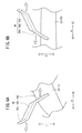
取付構造14は、ドアポケット18の上面24において、車両の前方方向である矢印A1方向側に設けられた第1取付用部材40と、車両の後方方向である矢印A2方向側にあって、凹部22を画成する上面24と側面とによって形成される角部に設けられた第2取付用部材42とから構成される。第1取付用部材40及び第2取付用部材42は、略同じ形状であり、ドアポケット18の矢印A方向に沿った幅W内に収まるように、樹脂成形等によりドアポケット18の上面24と一体的に構成されている。また、図2、図3、図9及び図10に示すように、上面24のうち、第2取付用部材42が設けられる矢印A2方向側は、矢印A2方向に向かって下方に傾斜する湾曲形状に構成されている。そのため、第2取付用部材42は、第1取付用部材40よりも低い位置に設けられている。
The mounting
第1取付用部材40は、図2、図3、図4B、図5B及び図9に示すように、車幅方向である矢印B方向(図7及び図8参照)から視ると略Z字状の形状であり、ワイヤハーネス12を保持する第1固定用部材44を取付可能に構成されている。具体的に、第1取付用部材40は、上面24から矢印C1方向に延出する第1延出部40aと、第1延出部40aの先端部から斜め前方(矢印A1方向及び矢印C1方向)に延出し且つ第1固定用部材44を取付可能な固定用部材保持部40bと、固定用部材保持部40bの先端部から矢印C1方向に延出する第2延出部40cとから構成される。
As shown in FIGS. 2, 3, 4B, 5B, and 9, the first mounting
すなわち、第1取付用部材40は、車両の前方に向かって、第1延出部40a、固定用部材保持部40b及び第2延出部40cが順に形成されている。従って、固定用部材保持部40bの一端から第1延出部40aが矢印C2方向に延出すると共に、他端から第2延出部40cが矢印C1方向に延出している。つまり、第1延出部40a及び第2延出部40cは、固定用部材保持部40bの両端から互いに離間する方向にそれぞれ延出している。
That is, as for the
第1固定用部材44は、ワイヤハーネス12の一部を保持した状態で、固定用部材保持部40bの略中央部分に取り付けられる。この場合、固定用部材保持部40bにおける第1固定用部材44の保持位置と、第1延出部40a及び第2延出部40cとの間の箇所は、隙間部46a、46cとして形成される。すなわち、第1延出部40a及び第2延出部40cは、固定用部材保持部40bにおける第1固定用部材44の保持位置を規制する位置規制部として機能する。このような隙間部46a、46cが設けられることにより、固定用部材保持部40bに対して第1固定用部材44を取り付けやすくなる。
The first fixing
一方、矢印A2方向側の角部に形成された第2取付用部材42は、図2、図3、図4A、図5A、図9及び図10に示すように、第1取付用部材40と同様に、矢印B方向(図7及び図8参照)から視ると略Z字状の形状であり、ワイヤハーネス12を保持する第2固定用部材48を取付可能に構成されている。具体的に、第2取付用部材42は、前記角部から矢印C1方向に延出する第1延出部42aと、第1延出部42aの先端部から斜め後方(矢印A2方向及び矢印C1方向)に延出し且つ第2固定用部材48を取付可能な固定用部材保持部42bと、固定用部材保持部42bの先端部から矢印C1方向に延出する第2延出部42cとから構成される。
On the other hand, the second mounting
すなわち、第2取付用部材42は、車両の後方に向かって、第1延出部42a、固定用部材保持部42b及び第2延出部42cが順に形成されている。従って、第1取付用部材40の場合と同様に、第1延出部42a及び第2延出部42cは、固定用部材保持部42bの両端から互いに離間する方向(矢印C1方向及び矢印C2方向)にそれぞれ延出している。
That is, as for the
第2固定用部材48は、ワイヤハーネス12の一部を保持した状態で、固定用部材保持部42bの略中央部分に取り付けられるが、固定用部材保持部42bにおける第2固定用部材48の保持位置と、第1延出部42a及び第2延出部42cとの間の箇所は、隙間部50a、50cとして形成される。すなわち、第1延出部42a及び第2延出部42cは、固定用部材保持部42bにおける第2固定用部材48の保持位置を規制する位置規制部として機能し、従って、隙間部50a、50cの存在によって、固定用部材保持部42bに対し第2固定用部材48を取り付けやすくなる。
The second fixing
このように、第1取付用部材40は、矢印A1方向に向かって上面24から延出すると共に、第2取付用部材42は、矢印A2方向に向かって上面24における矢印A2方向側の角部から延出している。すなわち、第1取付用部材40及び第2取付用部材42は、矢印A方向に沿って、互いに離間する方向に延出している。また、第1取付用部材40及び第2取付用部材42は、前述のように、幅W内で収まるように、上面24と一体的に構成されている。さらに、固定用部材保持部40b、42bに対して、第1延出部40a、42aと、第2延出部40c、42cとは、それぞれ、互いに離間する方向に延出している。
Thus, the first mounting
そのため、ワイヤハーネス12を第1固定用部材44及び第2固定用部材48で保持し、第1固定用部材44を第1取付用部材40の固定用部材保持部40bに取り付けると共に、第2固定用部材48を第2取付用部材42の固定用部材保持部42bに取り付ければ、上面24から所定高さ(距離H)だけワイヤハーネス12を離間させた状態で保持することができる。すなわち、取付構造14では、ワイヤハーネス12と上面24との間に第1取付用部材40及び第2取付用部材42を設けた状態で、ワイヤハーネス12を保持することができる。
Therefore, the
なお、本実施形態では、上述のようにワイヤハーネス12を保持することができるのであれば、第1取付用部材40及び第2取付用部材42の形状を、図6A及び図6Bに示す形状に変更することも可能である。図6A及び図6Bは、第1取付用部材40及び第2取付用部材42の変形例をそれぞれ図示したものである。第1取付用部材40において、第1延出部40a及び第2延出部40cは、斜め前方にそれぞれ延出すると共に、第2取付用部材42において、第1延出部42a及び第2延出部42cは、斜め後方にそれぞれ延出している。このようにすれば、第1固定用部材44及び第2固定用部材48での固定用部材保持部40b、42bに対する取付スペースをより広く確保することができる。
In addition, in this embodiment, if the
図7及び図8は、ワイヤハーネス12を保持する第1固定用部材44及び第2固定用部材48が、第1取付用部材40及び第2取付用部材42に対してそれぞれ取り付けられた状態を、車両の前後方向(矢印A方向)に沿って視た場合を図示したものである。
7 and 8 show a state in which the first fixing
第1固定用部材44及び第2固定用部材48は、略同一形状を有する。
The first fixing
具体的に、第1固定用部材44は、固定用部材保持部40bを狭持するクリップ部44aと、該クリップ部44aの上板部分に設けられたバンド係止部44bと、ワイヤハーネス12に巻き付けた状態で、先端部がバンド係止部44bを挿通することによりワイヤハーネス12を締め付けるバンド44cとから構成される。すなわち、バンド係止部44b及びバンド44cは、ワイヤハーネス12に対する結束バンド(ケーブルタイ)として機能し、ワイヤハーネス12が締付固定された状態で、固定用部材保持部40bの車両外側部分(矢印B2方向側の箇所)をクリップ部44aで挟むことにより、ワイヤハーネス12及び第1固定用部材44を固定用部材保持部40bに取り付けることができる。なお、クリップ部44aを開いて矢印B2方向に退動させると、固定用部材保持部40bからワイヤハーネス12及び第1固定用部材44を取り外すことができる。
Specifically, the first fixing
一方、第2固定用部材48は、固定用部材保持部42bを挟み込むクリップ部48aと、該クリップ部48aの上板部分に設けられたバンド係止部48bと、ワイヤハーネス12に巻き付けた状態で、先端部がバンド係止部48bを挿通することによりワイヤハーネス12を締め付けるバンド48cとから構成される。この場合でも、バンド係止部48b及びバンド48cは、ワイヤハーネス12に対する結束バンドとして機能し、ワイヤハーネス12が締付固定された状態で、固定用部材保持部42bの矢印B2方向側の箇所をクリップ部48aで狭持することにより、ワイヤハーネス12及び第2固定用部材48を固定用部材保持部42bに取り付けることができる。なお、クリップ部48aを開いて矢印B2方向に退動させると、固定用部材保持部42bからワイヤハーネス12及び第2固定用部材48を取り外すことができる。
On the other hand, the second fixing
そして、第1取付用部材40及び第2取付用部材42は、図8に示すように、ドアポケット18を構成する上面24(第1面)に加え、矢印C1方向に延出する上端部26(第2面)にも連結されている。すなわち、第1取付用部材40及び第2取付用部材42は、上面24における矢印B2方向側の箇所と上端部26との間に設けられ、上面24及び上端部26と一体的に構成されている。
As shown in FIG. 8, the first mounting
この場合、第1延出部40a、42aは、上面24及び上端部26と連結され、固定用部材保持部40b、42b及び第2延出部40c、42cは、上端部26とそれぞれ連結されている。また、矢印C方向に沿ったワイヤハーネス12と上面24との間の距離Hは、矢印B方向に沿ったワイヤハーネス12と上端部26との間の距離Dよりも短く設定されている(H<D)。
In this case, the first extending
また、固定用部材保持部40b、42bは、矢印B方向に沿って略水平に上端部26から延出している。これに対して、上面24は、上端部26から矢印B2方向に向かって下方に傾斜している。つまり、固定用部材保持部40b、42bと上面24との間隔は、車両の外側である矢印B2方向に向かうにつれて広がるように設定されている。
The fixing
なお、図8に示すように、第1延出部40a、42aの矢印C方向に沿った長さ(高さ)は、上面24が傾斜していることにより、矢印B2方向に向かうにつれて長くなる。一方、固定用部材保持部40b、42b及び第2延出部40c、42cの矢印C方向に沿った各長さは、それぞれ、矢印B方向に沿って略同じ長さに維持されている。また、第1延出部40a、42aの上端部26側の高さは、固定用部材保持部40b、42b及び第2延出部40c、42cの上端部26側の高さと、略同じ大きさに設定されている。
In addition, as shown in FIG. 8, the length (height) along the arrow C direction of the
以上説明したように、本実施形態に係るワイヤハーネス12の取付構造14によれば、第1取付用部材40及び第2取付用部材42と、取付対象であるドアライニング10を構成するドアポケット18の上面24及び上端部26とが一体的に構成されているので、ワイヤハーネス12を第1固定用部材44及び第2固定用部材48に保持した状態で、第1固定用部材44を第1取付用部材40に取り付けると共に、第2固定用部材48を第2取付用部材42に取り付ければ、ドアポケット18に対するワイヤハーネス12の取付作業が完了する。従って、特許文献1の技術と比較して、ドアポケット18へのワイヤハーネス12の取付作業性を向上することができる。
As described above, according to the mounting
また、第1取付用部材40及び第2取付用部材42がドアポケット18の上面24及び上端部26に連結されているので、第1取付用部材40及び第2取付用部材42の剛性を向上させることができる。
Further, since the first mounting
さらに、第1取付用部材40では、固定用部材保持部40bにおける第1固定用部材44の保持位置と、第1延出部40a及び第2延出部40cとの間の箇所が隙間部46a、46cとして形成される。一方、第2取付用部材42でも、固定用部材保持部42bにおける第2固定用部材48の保持位置と、第1延出部42a及び第2延出部42cとの間の箇所が隙間部50a、50cとして形成される。これにより、隙間部46a、46c、50a、50cがない場合と比較して、第1固定用部材44及び第2固定用部材48の取付スペースを広く取ることができる。この結果、第1固定用部材44を第1取付用部材40に容易に取り付けると共に、第2固定用部材48を第2取付用部材42に容易に取り付けることが可能となり、取付作業性を一層向上することができる。
Further, in the first mounting
しかも、第1取付用部材40及び第2取付用部材42において、第1延出部40a、42a及び第2延出部40c、42cは、互いに離間する方向に延出しているので、固定用部材保持部40bに対する第1固定用部材44の取付時及び取り外し時や、固定用部材保持部42bに対する第2固定用部材48の取付時及び取り外し時に、第1延出部40a、42a及び第2延出部40c、42cが邪魔になることを抑制することができる。また、このように構成されることで、第1取付用部材40及び第2取付用部材42を型構造的にも作りやすい形状とすることができる。なお、図6の変形例のように構成すれば、固定用部材保持部40b、42bでの第1固定用部材44及び第2固定用部材48の取付スペースが広がるので、取付作業が一層容易なものとなる。
Moreover, in the first mounting
また、第1延出部40a、42aがドアポケット18の上面24及び上端部26にそれぞれ連結され、固定用部材保持部40b、42b及び第2延出部40c、42cが上端部26に連結されているため、第1延出部40a、42a、固定用部材保持部40b、42b及び第2延出部40c、42cの剛性を向上することができる。
The first extending
さらに、第1取付用部材40及び第2取付用部材42は、ドアポケット18の上面24から上方に延出し、第1固定用部材44及び第2固定用部材48は、ワイヤハーネス12と上面24との間で、第1取付用部材40及び第2取付用部材42によりそれぞれ支持される。これにより、上面24から延出される第1取付用部材40及び第2取付用部材42の長さは、上端部26から矢印B方向に沿って延出する場合と比較して、短くすることができる。すなわち、図8に示すように、ドアポケット18に対してワイヤハーネス12を取り付けるための距離は、上面24で取り付ける場合(距離H)の方が、上端部26で取り付ける場合(距離D)よりも確実に短い(H<D)。従って、本実施形態によれば、第1取付用部材40及び第2取付用部材42が肥大化することを回避することができる。
Further, the first mounting
さらに、矢印B2方向に向かうにつれて、固定用部材保持部40b、42bとドアポケット18の上面24との間隔が広がるので、車両にドアライニング10を組み込む前に、第1取付用部材40及び第2取付用部材42に第1固定用部材44及び第2固定用部材48をそれぞれ取り付ける際、第1固定用部材44及び第2固定用部材48の取付作業が容易になる。
Further, as the distance between the fixing
さらにまた、図2、図3及び図9に示すように、本実施形態では、矢印A方向に沿って互いに広がるように、第1取付用部材40及び第2取付用部材42がそれぞれ上面24に設けられている。この場合、第1取付用部材40の第2延出部40cと第2取付用部材42の第2延出部42cとの間の距離をW1とすれば、該距離W1は、二点鎖線に示す第1取付用部材40と第2取付用部材42とが互いに近づくように向かい合う場合での各第2延出部40c、42c間の距離W2と比較し、確実に広くなる(W1>W2)。このように、本実施形態では、上面24での第1取付用部材40及び第2取付用部材42間のスペースが広くなって、該スペースを有効利用することができる。また、スペースが広がることで、第1取付用部材40及び第2取付用部材42に対する第1固定用部材44及び第2固定用部材48の取付作業が一層容易なものとなる。
Furthermore, as shown in FIGS. 2, 3, and 9, in the present embodiment, the first mounting
また、図10に二点鎖線で示すように、第1延出部42aが矢印A2方向側に形成されていれば、第1延出部42aが長くなってしまい、第2取付用部材42の肥大化を招くと共に、ドアポケット18の周辺の部材に対して第2取付用部材42の存在が邪魔になる。これに対して、本実施形態では、第1延出部42a、固定用部材保持部42b及び第2延出部42cが矢印A2方向に向かって順に形成されているため、長さh分だけ、第2取付用部材42の肥大化を抑制することができる。この結果、第2取付用部材42がドアポケット18の周辺の部材にとって邪魔になることを回避することができる。
Further, as shown by a two-dot chain line in FIG. 10, if the
さらに、本実施形態では、第2取付用部材42が上面24及び側面により画成される矢印A2方向の角部に設けられている。角部は剛性が高いため、このような箇所に第2取付用部材42に設ければ、第2取付用部材42の剛性を一層高めることができる。
Further, in the present embodiment, the second mounting
さらにまた、本実施形態では、ドアポケット18の矢印A方向に沿った幅W内に収まるように、第1取付用部材40の第2延出部40cと、第2取付用部材42の第2延出部42cとがそれぞれ形成されているので、ドアポケット18の周辺の部材に対して、第2延出部40c、42cが邪魔になることを回避することができる。
Furthermore, in this embodiment, the second extending
なお、本発明は、上記した実施形態に限らず、本発明の要旨を逸脱することなく、種々の構成を採り得ることは当然可能である。 It should be noted that the present invention is not limited to the above-described embodiment, and it is naturally possible to adopt various configurations without departing from the gist of the present invention.
10…ドアライニング 12…ワイヤハーネス
14…取付構造 18…ドアポケット
24…上面 26…上端部
40…第1取付用部材 40a、42a…第1延出部
40b、42b…固定用部材保持部 40c、42c…第2延出部
42…第2取付用部材 44…第1固定用部材
44a、48a…クリップ部 44b、48b…バンド係止部
44c、48c…バンド
46a、46c、50a、50c…隙間部 48…第2固定用部材
DESCRIPTION OF
Claims (9)
前記取付用部材は、前記固定用部材を保持するための固定用部材保持部を備えると共に、前記取付対象と一体的に構成されている
ことを特徴とする線状部材の取付構造。 In the mounting structure for mounting the fixing member to the mounting member provided in the mounting target in a state where the linear member is held by the fixing member,
The mounting member has a fixing member holding portion for holding the fixing member, and is configured integrally with the mounting target.
前記取付対象は、第1面と、該第1面に連なり且つ前記第1面とは異なる方向に延出する第2面とを有し、
前記取付用部材の少なくとも一部は、前記第1面と前記第2面とに連結されている
ことを特徴とする線状部材の取付構造。 The mounting structure according to claim 1,
The attachment object has a first surface and a second surface that extends to the first surface and extends in a direction different from the first surface;
At least a part of the mounting member is connected to the first surface and the second surface. A linear member mounting structure, wherein:
前記取付用部材は、前記固定用部材保持部における前記固定用部材の保持位置を規制する位置規制部をさらに備え、
前記固定用部材保持部において、前記固定用部材の保持位置と、前記位置規制部との間の箇所は、隙間部として構成される
ことを特徴とする線状部材の取付構造。 In the mounting structure according to claim 1 or 2,
The mounting member further includes a position restricting portion that restricts a holding position of the fixing member in the fixing member holding portion,
In the fixing member holding portion, a portion between the holding position of the fixing member and the position restricting portion is configured as a gap portion.
前記取付用部材は、前記固定用部材保持部と、該固定用部材保持部の一端から延出する第1延出部と、前記固定用部材保持部の他端から延出する第2延出部とから構成され、
前記位置規制部としての前記第1延出部及び前記第2延出部は、互いに離間する方向に延出している
ことを特徴とする線状部材の取付構造。 In the mounting structure according to claim 3,
The mounting member includes the fixing member holding portion, a first extending portion extending from one end of the fixing member holding portion, and a second extension extending from the other end of the fixing member holding portion. And consists of
The linear member mounting structure, wherein the first extending portion and the second extending portion as the position restricting portion extend in directions away from each other.
前記第1延出部は、前記第1面及び前記第2面にそれぞれ連結され、
前記固定用部材保持部及び前記第2延出部は、前記第2面に連結されている
ことを特徴とする線状部材の取付構造。 The mounting structure according to claim 4,
The first extension part is connected to the first surface and the second surface, respectively.
The fixing structure of the linear member, wherein the fixing member holding portion and the second extending portion are connected to the second surface.
前記取付対象は、車両のドアライニングであり、
前記第1面は、前記ドアライニングを構成するドアポケットでの前記車両の外側の面であり、
前記第2面は、前記ドアライニングの側面であり、
前記固定用部材は、前記ドアポケットでの前記車両の外側の面から延出した前記取付用部材により、前記線状部材と前記ドアポケットでの前記車両の外側の面との間で支持される
ことを特徴とする線状部材の取付構造。 In the mounting structure according to any one of claims 2 to 5,
The mounting object is a door lining of a vehicle,
The first surface is an outer surface of the vehicle at a door pocket constituting the door lining,
The second surface is a side surface of the door lining,
The fixing member is supported between the linear member and the outer surface of the vehicle at the door pocket by the mounting member extending from the outer surface of the vehicle at the door pocket. An attachment structure for a linear member, characterized by that.
前記第2面から離間するにつれて、前記固定用部材保持部と前記第1面との間隔が広がる
ことを特徴とする線状部材の取付構造。 In the attachment structure according to any one of claims 2 to 6,
As the distance from the second surface increases, the distance between the fixing member holding portion and the first surface increases.
前記第1面には、第1取付用部材が前記取付対象の前方側に設けられると共に、第2取付用部材が前記取付対象の後方側に設けられ、
前記第1取付用部材では、前記取付対象の前方に向かうように、第1延出部、固定用部材保持部及び第2延出部が順に形成され、
前記第2取付用部材では、前記取付対象の後方に向かうように、第1延出部、固定用部材保持部及び第2延出部が順に形成されている
ことを特徴とする線状部材の取付構造。 In the mounting structure according to any one of claims 2 to 7,
On the first surface, a first attachment member is provided on the front side of the attachment object, and a second attachment member is provided on the rear side of the attachment object,
In the first attachment member, a first extension portion, a fixing member holding portion, and a second extension portion are formed in order so as to go forward of the attachment target,
In the second attachment member, a first extension part, a fixing member holding part, and a second extension part are formed in order so as to go to the rear of the attachment target. Mounting structure.
前記第1取付用部材の第2延出部と、前記第2取付用部材の第2延出部とは、前記取付対象の前後方向の幅に収まるように、それぞれ形成されている
ことを特徴とする線状部材の取付構造。 The mounting structure according to claim 8,
The second extension portion of the first attachment member and the second extension portion of the second attachment member are formed so as to be within the width in the front-rear direction of the attachment target, respectively. The mounting structure of the linear member.
Priority Applications (2)
| Application Number | Priority Date | Filing Date | Title |
|---|---|---|---|
| JP2012051786A JP5872932B2 (en) | 2012-03-08 | 2012-03-08 | Mounting structure for linear members |
| PCT/JP2013/053036 WO2013132956A1 (en) | 2012-03-08 | 2013-02-08 | Structure for mounting linear member |
Applications Claiming Priority (1)
| Application Number | Priority Date | Filing Date | Title |
|---|---|---|---|
| JP2012051786A JP5872932B2 (en) | 2012-03-08 | 2012-03-08 | Mounting structure for linear members |
Publications (3)
| Publication Number | Publication Date |
|---|---|
| JP2013188024A true JP2013188024A (en) | 2013-09-19 |
| JP2013188024A5 JP2013188024A5 (en) | 2015-04-23 |
| JP5872932B2 JP5872932B2 (en) | 2016-03-01 |
Family
ID=49116440
Family Applications (1)
| Application Number | Title | Priority Date | Filing Date |
|---|---|---|---|
| JP2012051786A Active JP5872932B2 (en) | 2012-03-08 | 2012-03-08 | Mounting structure for linear members |
Country Status (2)
| Country | Link |
|---|---|
| JP (1) | JP5872932B2 (en) |
| WO (1) | WO2013132956A1 (en) |
Citations (4)
| Publication number | Priority date | Publication date | Assignee | Title |
|---|---|---|---|---|
| JPH10285755A (en) * | 1997-03-28 | 1998-10-23 | Harness Sogo Gijutsu Kenkyusho:Kk | Wiring harness attachment structure |
| JP2005073309A (en) * | 2003-08-25 | 2005-03-17 | Sumitomo Wiring Syst Ltd | Fixed structure of wire harness |
| JP2010132242A (en) * | 2008-12-08 | 2010-06-17 | Kanto Auto Works Ltd | Door trim board for automobile, and back door for automobile |
| JP2011073655A (en) * | 2009-10-02 | 2011-04-14 | Kawasaki Heavy Ind Ltd | Motorcycle wiring device |
-
2012
- 2012-03-08 JP JP2012051786A patent/JP5872932B2/en active Active
-
2013
- 2013-02-08 WO PCT/JP2013/053036 patent/WO2013132956A1/en active Application Filing
Patent Citations (4)
| Publication number | Priority date | Publication date | Assignee | Title |
|---|---|---|---|---|
| JPH10285755A (en) * | 1997-03-28 | 1998-10-23 | Harness Sogo Gijutsu Kenkyusho:Kk | Wiring harness attachment structure |
| JP2005073309A (en) * | 2003-08-25 | 2005-03-17 | Sumitomo Wiring Syst Ltd | Fixed structure of wire harness |
| JP2010132242A (en) * | 2008-12-08 | 2010-06-17 | Kanto Auto Works Ltd | Door trim board for automobile, and back door for automobile |
| JP2011073655A (en) * | 2009-10-02 | 2011-04-14 | Kawasaki Heavy Ind Ltd | Motorcycle wiring device |
Also Published As
| Publication number | Publication date |
|---|---|
| WO2013132956A1 (en) | 2013-09-12 |
| JP5872932B2 (en) | 2016-03-01 |
Similar Documents
| Publication | Publication Date | Title |
|---|---|---|
| US9488202B2 (en) | Clip | |
| CN103190047B (en) | Band clip | |
| EP2703228B1 (en) | Protector | |
| JP5915258B2 (en) | Bumper mounting structure | |
| JP6212329B2 (en) | Exterior member | |
| JP5446043B2 (en) | Instrument panel structure | |
| CN107615415B (en) | Noise counter plan component | |
| JP2014044890A (en) | Holding structure of optional connector | |
| JP2013005605A (en) | Corrugate tube with pathway holding member and wire harness | |
| JP5872932B2 (en) | Mounting structure for linear members | |
| JP2012217226A (en) | Wiring harness fixture | |
| JP5910581B2 (en) | Cable tie mounting structure | |
| WO2019103030A1 (en) | Wiring harness protector and harness assembly | |
| JP2016189683A (en) | Protector | |
| JP2003054330A (en) | Wire harness assembly type vehicle parts | |
| JP2017175710A (en) | Connector for wire harness | |
| JP5870702B2 (en) | Harness clamp | |
| JP6852646B2 (en) | Instrument panel mounting structure | |
| JP2017158285A (en) | Wiring harness | |
| JP2013074747A (en) | Wire harness and cable fixture | |
| US10144370B2 (en) | Cable holder | |
| JP5569870B2 (en) | Bracket structure | |
| JP2015000695A (en) | Holding structure of linear member | |
| JP2012010474A (en) | On-vehicle wire harness and wire clamp | |
| JP2018059610A (en) | Clip for locking of wire harness |
Legal Events
| Date | Code | Title | Description |
|---|---|---|---|
| A521 | Request for written amendment filed |
Free format text: JAPANESE INTERMEDIATE CODE: A523 Effective date: 20150306 |
|
| A621 | Written request for application examination |
Free format text: JAPANESE INTERMEDIATE CODE: A621 Effective date: 20150306 |
|
| TRDD | Decision of grant or rejection written | ||
| A01 | Written decision to grant a patent or to grant a registration (utility model) |
Free format text: JAPANESE INTERMEDIATE CODE: A01 Effective date: 20151215 |
|
| A61 | First payment of annual fees (during grant procedure) |
Free format text: JAPANESE INTERMEDIATE CODE: A61 Effective date: 20160114 |
|
| R150 | Certificate of patent or registration of utility model |
Ref document number: 5872932 Country of ref document: JP Free format text: JAPANESE INTERMEDIATE CODE: R150 |
|
| R250 | Receipt of annual fees |
Free format text: JAPANESE INTERMEDIATE CODE: R250 |
|
| R250 | Receipt of annual fees |
Free format text: JAPANESE INTERMEDIATE CODE: R250 |
|
| R250 | Receipt of annual fees |
Free format text: JAPANESE INTERMEDIATE CODE: R250 |
|
| R250 | Receipt of annual fees |
Free format text: JAPANESE INTERMEDIATE CODE: R250 |
|
| R250 | Receipt of annual fees |
Free format text: JAPANESE INTERMEDIATE CODE: R250 |
|
| R250 | Receipt of annual fees |
Free format text: JAPANESE INTERMEDIATE CODE: R250 |