JP2013184643A - Vehicle and control method for vehicle - Google Patents

Vehicle and control method for vehicle Download PDF

Info

Publication number
JP2013184643A
JP2013184643A JP2012053194A JP2012053194A JP2013184643A JP 2013184643 A JP2013184643 A JP 2013184643A JP 2012053194 A JP2012053194 A JP 2012053194A JP 2012053194 A JP2012053194 A JP 2012053194A JP 2013184643 A JP2013184643 A JP 2013184643A
Authority
JP
Japan
Prior art keywords
power
vehicle
storage device
power storage
charging
Prior art date
Legal status (The legal status is an assumption and is not a legal conclusion. Google has not performed a legal analysis and makes no representation as to the accuracy of the status listed.)
Granted
Application number
JP2012053194A
Other languages
Japanese (ja)
Other versions
JP5831304B2 (en
Inventor
Shigeki Kinomura
茂樹 木野村
Tomoyuki Mizuno
朋行 水野
Current Assignee (The listed assignees may be inaccurate. Google has not performed a legal analysis and makes no representation or warranty as to the accuracy of the list.)
Toyota Motor Corp
Original Assignee
Toyota Motor Corp
Priority date (The priority date is an assumption and is not a legal conclusion. Google has not performed a legal analysis and makes no representation as to the accuracy of the date listed.)
Filing date
Publication date
Application filed by Toyota Motor Corp filed Critical Toyota Motor Corp
Priority to JP2012053194A priority Critical patent/JP5831304B2/en
Publication of JP2013184643A publication Critical patent/JP2013184643A/en
Application granted granted Critical
Publication of JP5831304B2 publication Critical patent/JP5831304B2/en
Active legal-status Critical Current
Anticipated expiration legal-status Critical

Links

Images

Classifications

    • YGENERAL TAGGING OF NEW TECHNOLOGICAL DEVELOPMENTS; GENERAL TAGGING OF CROSS-SECTIONAL TECHNOLOGIES SPANNING OVER SEVERAL SECTIONS OF THE IPC; TECHNICAL SUBJECTS COVERED BY FORMER USPC CROSS-REFERENCE ART COLLECTIONS [XRACs] AND DIGESTS
    • Y02TECHNOLOGIES OR APPLICATIONS FOR MITIGATION OR ADAPTATION AGAINST CLIMATE CHANGE
    • Y02TCLIMATE CHANGE MITIGATION TECHNOLOGIES RELATED TO TRANSPORTATION
    • Y02T10/00Road transport of goods or passengers
    • Y02T10/60Other road transportation technologies with climate change mitigation effect
    • Y02T10/62Hybrid vehicles
    • YGENERAL TAGGING OF NEW TECHNOLOGICAL DEVELOPMENTS; GENERAL TAGGING OF CROSS-SECTIONAL TECHNOLOGIES SPANNING OVER SEVERAL SECTIONS OF THE IPC; TECHNICAL SUBJECTS COVERED BY FORMER USPC CROSS-REFERENCE ART COLLECTIONS [XRACs] AND DIGESTS
    • Y02TECHNOLOGIES OR APPLICATIONS FOR MITIGATION OR ADAPTATION AGAINST CLIMATE CHANGE
    • Y02TCLIMATE CHANGE MITIGATION TECHNOLOGIES RELATED TO TRANSPORTATION
    • Y02T10/00Road transport of goods or passengers
    • Y02T10/60Other road transportation technologies with climate change mitigation effect
    • Y02T10/70Energy storage systems for electromobility, e.g. batteries

Abstract

PROBLEM TO BE SOLVED: To satisfy power requirement from the vehicle external that exceeds a discharge capacity of an in-vehicle battery.SOLUTION: A vehicle side ECU (electronic control unit) executes a program that contains: a step (S208) to select a second mode and a step (S210) to execute charge amount control, when receiving load information (YES in S200), and when a present SOC is smaller than a keeping SOC (YES in S202), and there is a setting for forced charging (YES in S204); and a step (S214) to select a first mode and a step (S216) to execute discharged capacity control, when the present SOC is not less than the keeping SOC (YES in S202), when there is no setting for forced charging nor user's charging request (NO in S206, and NO in S204), or charging is performed until the present SOC becomes the charging completion SOC (YES in S212).

Description

本発明は、車両に搭載された蓄電装置の電力を車両外部の電気負荷に供給する技術に関する。   The present invention relates to a technique for supplying electric power of a power storage device mounted on a vehicle to an electric load outside the vehicle.

特開2001−8380号公報(特許文献1)には、住宅とバッテリを搭載した車両との間で電力を授受する電力マネジメントシステムが開示される。   Japanese Patent Laying-Open No. 2001-8380 (Patent Document 1) discloses a power management system that transfers power between a house and a vehicle equipped with a battery.

特開2001−8380号公報JP 2001-8380 A

しかしながら、上述した公報に開示された電力マネジメントシステムにおいては、車両外部の住宅から車両に対してバッテリの放電能力を超える電力要求があった場合に、その電力要求を満足させることができないという問題がある。   However, in the power management system disclosed in the above-mentioned publication, there is a problem that when there is a power request exceeding the discharge capacity of the battery from a housing outside the vehicle to the vehicle, the power request cannot be satisfied. is there.

本発明は、上述した課題を解決するためになされたものであって、その目的は、車両外部からの車載バッテリの放電能力を超える電力要求を満足させるための車両および車両用制御方法を提供することである。   The present invention has been made to solve the above-described problems, and an object of the present invention is to provide a vehicle and a vehicle control method for satisfying a power requirement exceeding the discharge capacity of an in-vehicle battery from the outside of the vehicle. That is.

この発明のある局面に係る車両は、車両の外部の受電設備への電力の供給が可能な蓄電装置と、エンジンを動力源として蓄電装置および受電設備への電力の供給が可能な発電装置と、発電装置および蓄電装置のうちの少なくともいずれか一方から電力を受電設備に供給するように車両を制御するための制御装置とを含む。制御装置は、受電設備から電力の供給が要求された場合に蓄電装置の残容量がしきい値よりも小さいときには、発電装置を用いて蓄電装置を充電した後に蓄電装置および発電装置を用いて受電設備に電力を供給するように車両を制御する。   A vehicle according to an aspect of the present invention includes a power storage device capable of supplying power to a power receiving facility outside the vehicle, a power generation device capable of supplying power to the power storage device and the power receiving facility using an engine as a power source, And a control device for controlling the vehicle to supply power to the power receiving facility from at least one of the power generation device and the power storage device. When the remaining capacity of the power storage device is smaller than the threshold when power supply is requested from the power receiving facility, the control device charges the power storage device using the power generation device and then receives power using the power storage device and the power generation device. Control the vehicle to supply power to the facility.

好ましくは、制御装置は、蓄電装置の残容量がしきい値よりも小さい場合に強制的に蓄電装置を充電する第1充電モードと、蓄電装置の残容量がしきい値よりも小さい場合に利用者の要求に応じて蓄電装置を充電する第2充電モードとのうちのいずれか一方の充電モードに従って蓄電装置を充電するように車両を制御する。   Preferably, the control device uses the first charging mode for forcibly charging the power storage device when the remaining capacity of the power storage device is smaller than the threshold value, and when the remaining capacity of the power storage device is smaller than the threshold value. The vehicle is controlled to charge the power storage device according to any one of the second charging modes in which the power storage device is charged in response to the request of the person.

さらに好ましくは、制御装置は、発電装置の発電および蓄電装置の放電により受電設備の電力要求量に応じた電力を受電設備に供給するように車両を制御し、受電設備の電力要求量がしきい値よりも大きくなる場合には、蓄電装置の放電量を調節することによって電力要求量の変動に追従した電力を受電設備に供給するように車両を制御する。   More preferably, the control device controls the vehicle to supply the power receiving facility with power corresponding to the power required amount of the power receiving facility by power generation of the power generating device and discharge of the power storage device, and the power required amount of the power receiving facility is the threshold When the value is larger than the value, the vehicle is controlled so as to supply the power receiving facility with the power following the variation in the required power amount by adjusting the discharge amount of the power storage device.

さらに好ましくは、制御装置は、エンジンの冷却状態に応じて発電電力の上限値を決定する。   More preferably, the control device determines an upper limit value of the generated power according to the cooling state of the engine.

さらに好ましくは、制御装置は、発電装置による発電電力が一定になるようにエンジンを制御する。   More preferably, the control device controls the engine so that the power generated by the power generation device is constant.

この発明の他の局面に係る車両用制御方法は、車両の外部の受電設備への電力の供給が可能な蓄電装置と、エンジンを動力源として蓄電装置および受電設備への電力の供給が可能な発電装置とを搭載した車両に用いられる車両用制御方法である。この車両用制御方法は、受電設備から電力の供給が要求された場合に蓄電装置の残容量がしきい値よりも小さいときには、発電装置を用いて蓄電装置を充電するステップと、発電装置を用いて蓄電装置を充電した後に蓄電装置および発電装置を用いて受電設備に電力を供給するように車両を制御するステップとを含む。   A vehicle control method according to another aspect of the present invention is capable of supplying power to a power storage device and a power receiving facility using a power storage device capable of supplying power to a power receiving facility outside the vehicle and an engine as a power source. This is a vehicle control method used in a vehicle equipped with a power generation device. The vehicle control method includes a step of charging the power storage device using the power generation device when the remaining capacity of the power storage device is smaller than the threshold when power supply is requested from the power receiving facility, and the power generation device is used. And controlling the vehicle to supply power to the power receiving facility using the power storage device and the power generation device after charging the power storage device.

この発明によると、蓄電装置の残容量が低い場合に蓄電装置を充電した後に受電設備に電力を供給することができる。これにより、受電設備が要求する電力が増加した場合でも電力を蓄電装置と発電装置とを用いて受電設備の電力要求量の変動に追従した受電設備に供給することができる。したがって、車両外部からの車載バッテリの放電能力を超える電力要求を満足させるための車両および車両用制御方法を提供することができる。   According to this invention, when the remaining capacity of the power storage device is low, it is possible to supply power to the power receiving facility after charging the power storage device. As a result, even when the power required by the power receiving facility increases, the power can be supplied to the power receiving facility that follows the fluctuation in the power requirement of the power receiving facility using the power storage device and the power generation device. Therefore, it is possible to provide a vehicle and a vehicle control method for satisfying a power requirement exceeding the discharge capacity of the in-vehicle battery from the outside of the vehicle.

本実施の形態に係る車両を含む充放電システムの全体ブロック図である。1 is an overall block diagram of a charge / discharge system including a vehicle according to an embodiment. 図1の充放電システムの詳細図の一例である。It is an example of the detailed view of the charging / discharging system of FIG. 切替部の構成を示すブロック図である。It is a block diagram which shows the structure of a switching part. 本実施の形態に係る車両に搭載される車両側ECUの機能ブロック図である。It is a functional block diagram of vehicle side ECU mounted in the vehicle which concerns on this Embodiment. 第1モード選択時の電力の流れを示す図である。It is a figure which shows the flow of the electric power at the time of 1st mode selection. 第2モード選択時の電力の流れを示す図である。It is a figure which shows the flow of the electric power at the time of 2nd mode selection. 第3モード選択時の電力の流れを示す図である。It is a figure which shows the flow of the electric power at the time of 3rd mode selection. 車両側ECUで実行される、温存SOCを算出するためのプログラムの制御構造を示すフローチャートである。It is a flowchart which shows the control structure of the program for calculating preservation | save SOC performed by vehicle side ECU. 車両側ECUで実行される、現在のSOCに基づいて第1モードまたは第2モードを選択するためのプログラムの制御構造を示すフローチャートである。It is a flowchart which shows the control structure of the program for selecting a 1st mode or a 2nd mode based on the present SOC performed by vehicle side ECU. 車両側ECUで実行される、車両からの放電量に基づいて第3モードを選択するためのプログラムの制御構造を示すフローチャートである。It is a flowchart which shows the control structure of the program for selecting a 3rd mode based on the discharge amount from a vehicle performed by vehicle side ECU. 電力要求量とSOCとの変化を示すタイミングチャートである。It is a timing chart which shows the change of electric power demand and SOC.

以下、図面を参照しつつ、本発明の実施の形態は、説明される。以下の説明では、同一の部品には同一の符号が付されている。それらの名称および機能も同じである。したがってそれらについての詳細な説明は繰り返されない。   Hereinafter, embodiments of the present invention will be described with reference to the drawings. In the following description, the same parts are denoted by the same reference numerals. Their names and functions are also the same. Therefore, detailed description thereof will not be repeated.

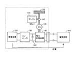
図1に示すように、本実施の形態における充放電システム1は、車両10と、住宅450とを含む。車両10と住宅450とは、充電ケーブル300によって接続される。   As shown in FIG. 1, charge / discharge system 1 in the present embodiment includes a vehicle 10 and a house 450. Vehicle 10 and house 450 are connected by charging cable 300.

本実施の形態に係る車両10は、駆動部20と、蓄電装置150と、コンバータ160と、平滑コンデンサ162と、車両側ECU(Electronic Control Unit)170と、第1PLC(Power Line Communications)装置172と、無線通信装置174と、通知部178と、電力変換装置180と、電圧センサ182と、インレット270とを含むハイブリッド車両である。   Vehicle 10 according to the present embodiment includes drive unit 20, power storage device 150, converter 160, smoothing capacitor 162, vehicle-side ECU (Electronic Control Unit) 170, and first PLC (Power Line Communications) device 172. The hybrid vehicle includes a wireless communication device 174, a notification unit 178, a power conversion device 180, a voltage sensor 182, and an inlet 270.

なお、本実施の形態に係る車両10は、図1に示すハイブリッド車両であるとして説明するが、車両10の外部の受電設備および車載の電気機器に電力を供給するための蓄電装置と、発電電力を用いて蓄電装置を充電するための発電機と、発電機の動力源となるエンジンとが搭載される車両であれば、特に、図1に示すハイブリッド車両の構成に限定されるものではない。   Although vehicle 10 according to the present embodiment will be described as the hybrid vehicle shown in FIG. 1, a power storage device for supplying power to a power receiving facility outside vehicle 10 and an on-vehicle electric device, and generated power 1 is not particularly limited to the configuration of the hybrid vehicle shown in FIG. 1, as long as the vehicle is equipped with a generator for charging the power storage device by using an engine and an engine serving as a power source for the generator.

駆動部20は、モータジュネレータ(以下「MG(Motor Generator)」とも称する。)120と、駆動輪130と、エンジン140と、動力分割機構145とを含む。   The drive unit 20 includes a motor generator (hereinafter also referred to as “MG (Motor Generator)”) 120, drive wheels 130, an engine 140, and a power split mechanism 145.

インレット270には、充電ケーブル300に備えられるコネクタ310が接続される。   A connector 310 provided in the charging cable 300 is connected to the inlet 270.

蓄電装置150は、充放電可能に構成された電力貯蔵要素である。蓄電装置150は、たとえば、リチウムイオン電池、ニッケル水素電池あるいは鉛蓄電池などの二次電池や、電気二重層キャパシタなどの蓄電素子を含んで構成される。   The power storage device 150 is a power storage element configured to be chargeable / dischargeable. The power storage device 150 includes, for example, a secondary battery such as a lithium ion battery, a nickel metal hydride battery, or a lead storage battery, and a power storage element such as an electric double layer capacitor.

蓄電装置150は、コンバータ160に供給するための直流電力あるいはコンバータ160から供給される直流電力を蓄える。蓄電装置150は、コンバータ160を介在して電力変換装置180に接続される。蓄電装置150は、車両を走行するための駆動力の発生に用いられる直流電力を供給する。蓄電装置150は、MG120で発電された電力を蓄電する。   Power storage device 150 stores DC power supplied to converter 160 or DC power supplied from converter 160. Power storage device 150 is connected to power conversion device 180 through converter 160. The power storage device 150 supplies DC power used to generate driving force for traveling the vehicle. Power storage device 150 stores the power generated by MG 120.

蓄電装置150は、いずれも図示しないが、蓄電装置150の電圧を検出するための電圧センサ、および、蓄電装置150に入出力される電流を検出するための電流センサをさらに含む。電圧センサは、検出した電圧を示す信号を車両側ECU170に送信する。電流センサは、検出した電流を示す信号を車両側ECU170に送信する。   Although not shown, power storage device 150 further includes a voltage sensor for detecting the voltage of power storage device 150 and a current sensor for detecting a current input to and output from power storage device 150. The voltage sensor transmits a signal indicating the detected voltage to vehicle-side ECU 170. The current sensor transmits a signal indicating the detected current to the vehicle side ECU 170.

コンバータ160は、蓄電装置150の放電時においては、車両側ECU170からの制御信号PWCに基づいて蓄電装置150側の電圧を昇圧して電力変換装置180に供給する。   Converter 160 boosts the voltage on power storage device 150 side and supplies it to power conversion device 180 based on control signal PWC from vehicle side ECU 170 when power storage device 150 is discharged.

さらに、コンバータ160は、蓄電装置150の充電時においては、車両側ECU170からの制御信号PWCに基づいて電力変換装置180側の電圧を降圧して蓄電装置150に供給する。   Furthermore, converter 160 steps down the voltage on power conversion device 180 side and supplies it to power storage device 150 based on control signal PWC from vehicle side ECU 170 when power storage device 150 is charged.

本実施の形態においては、コンバータ160は、蓄電装置の放電時に蓄電装置側の電圧を昇圧し、蓄電装置の充電時に電力変換装置180側の電圧を降圧するとして説明するが、特にこのような動作に限定されるものではない。たとえば、コンバータ160は、蓄電装置の放電時に蓄電装置側の電圧を降圧し、蓄電装置の充電時に電力変換装置180側の電圧を昇圧するものであってもよい。   In the present embodiment, converter 160 is described as boosting the voltage on the power storage device side when discharging the power storage device, and stepping down the voltage on power conversion device 180 side when charging the power storage device. It is not limited to. For example, converter 160 may step down the voltage on the power storage device side when discharging the power storage device, and step up the voltage on the power conversion device 180 side when charging the power storage device.

平滑コンデンサ162は、コンバータ160と電力変換装置180との間の電圧を平滑化する。   Smoothing capacitor 162 smoothes the voltage between converter 160 and power conversion device 180.

電力変換装置180は、蓄電装置150およびMG120に接続される。電力変換装置180は、さらに、電力線ACL1,ACL2によってインレット270と接続される。   Power conversion device 180 is connected to power storage device 150 and MG 120. Power conversion device 180 is further connected to inlet 270 by power lines ACL1 and ACL2.

電力変換装置180は、蓄電装置150からの直流電力を3相の交流電力に変換してMG120に供給する機能と、蓄電装置150からの直流電力を単相の交流電力に変換して住宅450に供給する機能と、MG120からの3相の交流電力を単相の交流電力に変換して住宅450に供給する機能とを含む。電力変換装置180は、たとえば、インバータやトランス等を組み合わせることによって、上述した機能を実現するようにしてもよい。   Power conversion device 180 converts DC power from power storage device 150 into three-phase AC power and supplies it to MG 120, and converts DC power from power storage device 150 into single-phase AC power for housing 450. And a function of converting the three-phase AC power from the MG 120 into a single-phase AC power and supplying it to the house 450. The power conversion device 180 may realize the above-described functions by combining, for example, an inverter and a transformer.

電力変換装置180は、車両10の走行時においては、車両側ECU170からの制御信号PWEに基づいて蓄電装置150から供給される電力を、MG120を駆動するための電力に変換する。   Power conversion device 180 converts electric power supplied from power storage device 150 to electric power for driving MG 120 based on control signal PWE from vehicle-side ECU 170 when vehicle 10 is traveling.

電力変換装置180は、蓄電装置150の充電時においては、車両側ECU170からの制御信号PWEに基づいて、住宅450の系統電源402から供給される交流電力を、蓄電装置150が充電可能な直流電力に変換して、コンバータ160を経由して蓄電装置150に供給する。   When power storage device 150 is charged, power conversion device 180 is based on control signal PWE from vehicle-side ECU 170, and DC power that power storage device 150 can charge is AC power supplied from system power supply 402 of house 450. And supplied to the power storage device 150 via the converter 160.

あるいは、電力変換装置180は、車両10を住宅450の電源として用いる場合には、車両側ECU170からの制御信号PWEに基づいて、蓄電装置150から供給される直流電力、あるいは、後述するMG120において発電された発電電力を、住宅450内の家庭用電気機器に対応した交流電力に変換して、住宅450に供給する。   Alternatively, when using vehicle 10 as a power source for house 450, power conversion device 180 generates DC power supplied from power storage device 150 based on control signal PWE from vehicle-side ECU 170 or power generation in MG 120 described later. The generated generated power is converted into AC power corresponding to household electric appliances in the house 450 and supplied to the house 450.

MG120は、電力変換装置180と電気的に接続される。MG120の回転軸は、動力分割機構145を介在させて駆動輪130に接続される。MG120は、電力変換装置180から供給された電力を受けて、車両10を走行させるための駆動力を発生する。また、MG120は、駆動輪130からの回転力を受けて交流電力を発生させることによって回生制動力を発生させる。MG120は、発生した交流電力を電力変換装置180に供給する。車両側ECU170は、電力変換装置180に対して車両10の状態に応じて生成される回生トルク指令値を送信することによって回生制動力を制御する。MG120は、たとえば、永久磁石が埋設されたロータとY結線された三相コイルを有するステータとを備える三相交流電動発電機である。   MG 120 is electrically connected to power conversion device 180. The rotation shaft of MG 120 is connected to drive wheel 130 with power split mechanism 145 interposed. MG 120 receives the power supplied from power conversion device 180 and generates a driving force for driving vehicle 10. In addition, MG 120 generates a regenerative braking force by generating AC power in response to the rotational force from drive wheel 130. MG 120 supplies the generated AC power to power conversion device 180. The vehicle-side ECU 170 controls the regenerative braking force by transmitting a regenerative torque command value generated according to the state of the vehicle 10 to the power conversion device 180. The MG 120 is, for example, a three-phase AC motor generator including a rotor in which permanent magnets are embedded and a stator having a Y-connected three-phase coil.

MG120は、動力分割機構145を介在させてエンジン140とも接続される。車両側ECU170は、エンジン140およびMG120の駆動力が最適な比率となるように車両10を制御する。MG120は、エンジン140により駆動されることによって、発電機として動作する。MG120によって発電された電力(以下、発電電力と記載する)は、蓄電装置150に蓄電される。また、発電電力は、蓄電装置150の電力に代えてまたは加えて電力変換装置180およびインレット270を経由して住宅450内の家庭用電気機器等に供給され得る。   MG 120 is also connected to engine 140 with power split mechanism 145 interposed. The vehicle-side ECU 170 controls the vehicle 10 so that the driving forces of the engine 140 and the MG 120 have an optimal ratio. MG 120 operates as a generator when driven by engine 140. Electric power generated by MG 120 (hereinafter referred to as generated electric power) is stored in power storage device 150. In addition, the generated power can be supplied to household electric appliances in the house 450 via the power conversion device 180 and the inlet 270 instead of or in addition to the power of the power storage device 150.

なお、動力分割機構145と駆動輪130との間に駆動輪130に駆動トルクを付与する機能と回生制動時に発電する機能とを有する回転電機がさらに設けられてもよい。   A rotating electrical machine having a function of applying drive torque to drive wheel 130 and a function of generating power during regenerative braking may be further provided between power split mechanism 145 and drive wheel 130.

エンジン140は、たとえば、ガソリンエンジンやディーゼルエンジン等の内燃機関である。   The engine 140 is, for example, an internal combustion engine such as a gasoline engine or a diesel engine.

電圧センサ182は、電力線ACL1とACL2との間に接続され、電力線ACL1とACL2との間の電圧VACを検出する。電圧センサ182は、電圧VACを示す信号を車両側ECU170に送信する。   Voltage sensor 182 is connected between power lines ACL1 and ACL2, and detects voltage VAC between power lines ACL1 and ACL2. Voltage sensor 182 transmits a signal indicating voltage VAC to vehicle-side ECU 170.

車両側ECU170は、CPU(Central Processing Unit)(図1において図示せず)と、記憶装置または入出力バッファ等としての機能を有するメモリ171とを含む。車両側ECU170は、各センサ等からの信号の受信や各機器への制御指令の送信を行なうとともに、車両10および各機器の制御を行なう。なお、これらの制御については、ソフトウェアによる処理に限られず、専用のハードウェア(電子回路)で構築して処理することも可能である。   The vehicle-side ECU 170 includes a CPU (Central Processing Unit) (not shown in FIG. 1) and a memory 171 having a function as a storage device or an input / output buffer. The vehicle-side ECU 170 receives signals from the sensors and the like, transmits control commands to the devices, and controls the vehicle 10 and the devices. Note that these controls are not limited to software processing, and can be constructed and processed by dedicated hardware (electronic circuit).

車両側ECU170は、充電ケーブル300から、インレット270を経由して、接続信号CNCTおよびパイロット信号CPLTを受信する。車両側ECU170は、電圧センサ182から電圧VACの検出値を受信する。   Vehicle-side ECU 170 receives connection signal CNCT and pilot signal CPLT from charging cable 300 via inlet 270. Vehicle-side ECU 170 receives the detected value of voltage VAC from voltage sensor 182.

車両側ECU170は、蓄電装置150内に設置されたセンサ(図示せず)から電流、電圧、温度に関する検出値を受信して、蓄電装置150の残容量を示すSOC(State of Charge)を算出する。   Vehicle-side ECU 170 receives detection values relating to current, voltage, and temperature from a sensor (not shown) installed in power storage device 150 and calculates an SOC (State of Charge) indicating the remaining capacity of power storage device 150. .

車両側ECU170は、これらの情報に基づいて、蓄電装置150を充電あるいは住宅450へ放電するために、コンバータ160および電力変換装置180などを制御する。   Based on these pieces of information, vehicle-side ECU 170 controls converter 160, power conversion device 180, and the like in order to charge power storage device 150 or discharge it to house 450.

第1PLC装置172は、電力線241に接続される。第1PLC装置172は、住宅450の電力線441に接続された第2PLC装置404との間で電力線通信を行なう。第1PLC装置172と第2PLC装置404との間での電力線通信において、電力線241,341,441が通信経路として利用される。第1PLC装置172と第2PLC装置404との間での電力線通信は、充電ケーブル300が車両10および住宅450の双方に接続されることにより、すなわち、コンセント400とプラグ320とが接続され、かつ、コネクタ310とインレット270とが接続されることにより可能となる。   First PLC device 172 is connected to power line 241. First PLC device 172 performs power line communication with second PLC device 404 connected to power line 441 of house 450. In the power line communication between the first PLC device 172 and the second PLC device 404, the power lines 241, 341, 441 are used as communication paths. In the power line communication between the first PLC device 172 and the second PLC device 404, the charging cable 300 is connected to both the vehicle 10 and the house 450, that is, the outlet 400 and the plug 320 are connected, and This is made possible by connecting the connector 310 and the inlet 270.

第1PLC装置172は、たとえば、モデムを含む。第1PLC装置172は、住宅450の第2PLC装置404から高周波信号を電力線241を経由して受信する場合、受信した高周波信号からデータを復調する。第1PLC装置172は、復調したデータを車両側ECU170に送信する。   First PLC device 172 includes, for example, a modem. When receiving a high frequency signal from second PLC device 404 of house 450 via power line 241, first PLC device 172 demodulates data from the received high frequency signal. First PLC device 172 transmits the demodulated data to vehicle-side ECU 170.

また、第1PLC装置172は、車両側ECU170からデータを受信する場合に、受信したデータを高周波信号に変調する。第1PLC装置172は、変調した高周波信号を電力線241に出力する。   Further, when receiving data from the vehicle-side ECU 170, the first PLC device 172 modulates the received data into a high-frequency signal. The first PLC device 172 outputs the modulated high frequency signal to the power line 241.

なお、系統電源402の交流電力の周波数が、たとえば、50Hzまたは60Hzである場合、電力通信時に第1PLC装置172と第2PLC装置404との間で授受される高周波信号の周波数は、たとえば、数MHz〜数10MHzである。   Note that when the frequency of the AC power of the system power supply 402 is, for example, 50 Hz or 60 Hz, the frequency of the high-frequency signal exchanged between the first PLC device 172 and the second PLC device 404 during power communication is, for example, several MHz. ~ Tens of MHz.

無線通信装置174は、車両10の外部の無線通信装置と無線通信を行なう。本実施の形態において無線通信装置174は、住宅450内の無線通信装置408と無線通信を行なう。   The wireless communication device 174 performs wireless communication with a wireless communication device outside the vehicle 10. In the present embodiment, wireless communication device 174 performs wireless communication with wireless communication device 408 in house 450.

なお、無線通信には、たとえば、Zigbee(登録商標)、Bluetooth(登録商標)、IEEE802.11、あるいは、赤外線通信等の無線通信の規格が用いられるが、特にこれらの規格に限定されるものではない。   For wireless communication, for example, Zigbee (registered trademark), Bluetooth (registered trademark), IEEE 802.11, or wireless communication standards such as infrared communication are used. However, the wireless communication standards are not particularly limited to these standards. Absent.

通知部178は、車両10内の利用者に対して所定の情報を通知する。本実施の形態において、通知部178は、たとえば、LCD(Liquid Crystal Display)やLED(Light Emitting Diode)等により構成される表示装置を用いて利用者に対して所定の情報を通知する。なお、通知部178は、たとえば、音あるいは音声を発生させる音発生装置を用いて利用者に対して所定の情報を通知してもよい。   The notification unit 178 notifies the user in the vehicle 10 of predetermined information. In the present embodiment, the notification unit 178 notifies the user of predetermined information using, for example, a display device configured by an LCD (Liquid Crystal Display), an LED (Light Emitting Diode), or the like. Note that the notification unit 178 may notify the user of predetermined information using, for example, a sound generation device that generates sound or sound.

充電ケーブル300は、車両側の端部に設けられたコネクタ310と、系統電源側の端部に設けられたプラグ320と、充電回路遮断装置(以下、「CCID(Charging Circuit Interrupt Device)」とも称する。)330と、それぞれの機器間を接続して電力および制御信号を入出力する電線部340とを備える。充電ケーブル300は、車両10側に含まれるものであってもよいし、住宅450に含まれるものであってもよい。   The charging cable 300 is also referred to as a connector 310 provided at an end portion on the vehicle side, a plug 320 provided at an end portion on the system power supply side, and a charging circuit interrupting device (hereinafter referred to as “CCID (Charging Circuit Interrupt Device)”). .) 330 and a wire portion 340 for connecting the respective devices and inputting / outputting electric power and control signals. Charging cable 300 may be included on vehicle 10 side or may be included in house 450.

電線部340は、プラグ320とCCID330との間を接続する電線部340Aと、コネクタ310とCCID330との間を接続する電線部340Bとを含む。また、電線部340は、系統電源402からの電力を伝達するための電力線341を含む。   Electric wire portion 340 includes an electric wire portion 340 </ b> A that connects between plug 320 and CCID 330, and an electric wire portion 340 </ b> B that connects between connector 310 and CCID 330. Electric wire portion 340 includes a power line 341 for transmitting power from system power supply 402.

充電ケーブル300のプラグ320は、外部充電を行なう場合や車両10を住宅450の電源として用いる場合に住宅450の系統電源402のコンセント400に接続される。また、充電ケーブル300のコネクタ310は、上述したような場合に車両10のボディに設けられたインレット270に接続される。プラグ320とコンセント400とが接続され、コネクタ310とインレット270とが接続されることによって、系統電源402からの電力が車両10に伝達される。プラグ320は、コンセント400に取り付けたり、コンセント400から取り外したりすることができる。コネクタ310は、インレット270に取り付けたり、インレット270から取り外したりすることができる。   Plug 320 of charging cable 300 is connected to outlet 400 of system power supply 402 of house 450 when external charging is performed or when vehicle 10 is used as a power source of house 450. In addition, the connector 310 of the charging cable 300 is connected to an inlet 270 provided on the body of the vehicle 10 in the case described above. The plug 320 and the outlet 400 are connected, and the connector 310 and the inlet 270 are connected, whereby electric power from the system power supply 402 is transmitted to the vehicle 10. Plug 320 can be attached to or removed from outlet 400. The connector 310 can be attached to or removed from the inlet 270.

コネクタ310の内部には、接続検出回路312が設けられる。接続検出回路312は、インレット270とコネクタ310との接続状態を検出する。接続検出回路312は、接続状態を示す接続信号CNCTを、インレット270を経由して、車両10の車両側ECU170へ送信する。   A connection detection circuit 312 is provided inside the connector 310. The connection detection circuit 312 detects the connection state between the inlet 270 and the connector 310. The connection detection circuit 312 transmits a connection signal CNCT indicating the connection state to the vehicle side ECU 170 of the vehicle 10 via the inlet 270.

接続検出回路312については、図1に示すようなリミットスイッチとする構成とし、コネクタ310をインレット270に接続したときに、接続信号CNCTの電位が接地電位(0V)となるようにしてもよい。あるいは、接続検出回路312を所定の抵抗値を有する抵抗器(図示しない)とする構成とし、接続時に接続信号CNCTの電位を所定の電位に低下させるようにしてもよい。いずれの場合においても、車両側ECU170は、接続信号CNCTの電位を検出することによって、コネクタ310がインレット270に接続されたことを検出する。   The connection detection circuit 312 may be configured as a limit switch as shown in FIG. 1 so that when the connector 310 is connected to the inlet 270, the potential of the connection signal CNCT becomes the ground potential (0 V). Alternatively, the connection detection circuit 312 may be configured as a resistor (not shown) having a predetermined resistance value, and the potential of the connection signal CNCT may be lowered to a predetermined potential at the time of connection. In any case, vehicle-side ECU 170 detects that connector 310 is connected to inlet 270 by detecting the potential of connection signal CNCT.

CCID330は、CCIDリレー332と、コントロールパイロット回路334とを含む。CCIDリレー332は、充電ケーブル300内の電力線341に介挿される。CCIDリレー332は、コントロールパイロット回路334によって制御される。CCIDリレー332が開状態になるときは、電力線341の電路が遮断される。一方、CCIDリレー332が閉状態になるときは、住宅450から車両10に電力が供給されたり、あるいは、車両10から住宅450に電力が供給されたりする。   CCID 330 includes CCID relay 332 and control pilot circuit 334. CCID relay 332 is inserted into power line 341 in charging cable 300. The CCID relay 332 is controlled by the control pilot circuit 334. When the CCID relay 332 is in an open state, the electric circuit of the power line 341 is interrupted. On the other hand, when the CCID relay 332 is closed, electric power is supplied from the house 450 to the vehicle 10, or electric power is supplied from the vehicle 10 to the house 450.

コントロールパイロット回路334は、コネクタ310およびインレット270を経由して車両側ECU170へパイロット信号CPLTを出力する。このパイロット信号CPLTは、コントロールパイロット回路334から車両側ECU170へ充電ケーブル300の定格電流を通知するための信号である。また、パイロット信号CPLTは、車両側ECU170によって操作されるパイロット信号CPLTの電位に基づいて、車両側ECU170からCCIDリレー332を遠隔操作するための信号としても使用される。そして、コントロールパイロット回路334は、パイロット信号CPLTの電位変化に基づいてCCIDリレー332を制御する。   Control pilot circuit 334 outputs pilot signal CPLT to vehicle side ECU 170 via connector 310 and inlet 270. This pilot signal CPLT is a signal for notifying the rated current of charging cable 300 from control pilot circuit 334 to vehicle-side ECU 170. Pilot signal CPLT is also used as a signal for remotely operating CCID relay 332 from vehicle-side ECU 170 based on the potential of pilot signal CPLT operated by vehicle-side ECU 170. The control pilot circuit 334 controls the CCID relay 332 based on the potential change of the pilot signal CPLT.

上述のパイロット信号CPLTおよび接続信号CNCT、ならびに、インレット270およびコネクタ310の形状、端子配置などの構成は、たとえば、米国のSAE(Society of Automotive Engineers)や日本電動車両協会等において規格化されている。   The configuration of the pilot signal CPLT and the connection signal CNCT as well as the shapes and terminal arrangements of the inlet 270 and the connector 310 are standardized by, for example, SAE (Society of Automotive Engineers) in the United States, the Japan Electric Vehicle Association, etc. .

住宅450は、コンセント400と、系統電源402と、第2PLC装置404と、住宅側ECU406と、無線通信装置408と、通知部412と、切替部414と、電気負荷416と、電力線441とを含む。   House 450 includes an outlet 400, a system power supply 402, a second PLC device 404, a house-side ECU 406, a wireless communication device 408, a notification unit 412, a switching unit 414, an electric load 416, and a power line 441. .

本実施の形態において、系統電源402は、交流電源であるとして説明するが、たとえば、直流電源であってもよい。   In the present embodiment, system power supply 402 is described as an AC power supply, but may be a DC power supply, for example.

第2PLC装置404は、電力線441に接続される。第2PLC装置404は、第1PLC装置172との間で電力線通信を行なう。   Second PLC device 404 is connected to power line 441. Second PLC device 404 performs power line communication with first PLC device 172.

第2PLC装置404は、たとえば、モデムを含む。第2PLC装置404は、車両10の第1PLC装置172から高周波信号を電力線441を経由して受信する場合、受信した高周波信号からデータを復調する。第2PLC装置404は、復調したデータを住宅側ECU406に送信する。   The second PLC device 404 includes, for example, a modem. When receiving a high frequency signal from first PLC device 172 of vehicle 10 via power line 441, second PLC device 404 demodulates data from the received high frequency signal. Second PLC device 404 transmits the demodulated data to residential ECU 406.

また、第2PLC装置404は、住宅側ECU406からデータを受信する場合に、受信したデータを高周波信号に変調する。第2PLC装置404は、変調した高周波信号を電力線441に出力する。   In addition, when receiving data from the residential ECU 406, the second PLC device 404 modulates the received data into a high-frequency signal. Second PLC device 404 outputs the modulated high-frequency signal to power line 441.

住宅側ECU406は、CPU(図示せず)と、記憶装置または入出力バッファ等としての機能を有するメモリ407とを含む。住宅側ECU406は、車両側ECU170と通信が可能となった場合に、車両側ECU170を経由して、車両10に設けられる各センサ等からの信号の受信や車両10に搭載された各機器への制御指令の出力を行なうとともに、各機器の制御を行なう。なお、これらの制御については、ソフトウェアによる処理に限られず、専用のハードウェア(電子回路)で構築して処理することも可能である。   Residential ECU 406 includes a CPU (not shown) and a memory 407 that functions as a storage device or an input / output buffer. When communication with the vehicle-side ECU 170 becomes possible, the housing-side ECU 406 receives a signal from each sensor or the like provided in the vehicle 10 via the vehicle-side ECU 170 and sends it to each device mounted on the vehicle 10. The control command is output and each device is controlled. Note that these controls are not limited to software processing, and can be constructed and processed by dedicated hardware (electronic circuit).

無線通信装置408は、住宅450の外部あるいは内部の無線通信装置と無線通信を行なう。本実施の形態において無線通信装置408は、車両10の無線通信装置174との間で無線通信を行なう。   The wireless communication device 408 performs wireless communication with a wireless communication device outside or inside the house 450. In the present embodiment, wireless communication device 408 performs wireless communication with wireless communication device 174 of vehicle 10.

車両側ECU170と住宅側ECU406との通信は、コンセント400とプラグ320とが接続され、かつ、コネクタ310とインレット270とが接続された場合に行なわれてもよいし、あるいは、車両10と住宅450とが通信可能な範囲内である場合に行なわれてもよい。本実施の形態においては、コンセント400とプラグ320とが接続され、かつ、コネクタ310とインレット270とが接続された場合に、車両側ECU170と住宅側ECU406とが連携して車両10から住宅450に電力を供給したり、あるいは、住宅450から車両10に電力を供給したりする。   Communication between vehicle-side ECU 170 and house-side ECU 406 may be performed when outlet 400 and plug 320 are connected, and connector 310 and inlet 270 are connected, or vehicle 10 and house 450 are connected. May be performed in a range where communication is possible. In the present embodiment, when outlet 400 and plug 320 are connected and connector 310 and inlet 270 are connected, vehicle-side ECU 170 and house-side ECU 406 cooperate to move from vehicle 10 to house 450. Electric power is supplied, or electric power is supplied from the house 450 to the vehicle 10.

車両側ECU170と住宅側ECU406とは、コンセント400とプラグ320とが接続され、かつ、コネクタ310とインレット270とが接続された場合に、無線通信装置174と無線通信装置408とを用いた無線通信により通信を行なってもよい。   The vehicle-side ECU 170 and the housing-side ECU 406 communicate with each other using the wireless communication device 174 and the wireless communication device 408 when the outlet 400 and the plug 320 are connected and the connector 310 and the inlet 270 are connected. Communication may be performed by

あるいは、車両側ECU170と住宅側ECU406とは、コンセント400とプラグ320とが接続され、かつ、コネクタ310とインレット270とが接続された場合に、第1PLC装置172と第2PLC装置404とを用いた電力線通信により通信を行なってもよい。   Alternatively, the vehicle side ECU 170 and the house side ECU 406 use the first PLC device 172 and the second PLC device 404 when the outlet 400 and the plug 320 are connected and the connector 310 and the inlet 270 are connected. Communication may be performed by power line communication.

あるいは、車両側ECU170と住宅側ECU406とは、コンセント400とプラグ320とが接続され、かつ、コネクタ310とインレット270とが接続された場合に、上述の無線通信と電力線通信とを併用して通信を行なってもよい。   Alternatively, the vehicle-side ECU 170 and the housing-side ECU 406 communicate with each other using the above-described wireless communication and power line communication when the outlet 400 and the plug 320 are connected and the connector 310 and the inlet 270 are connected. May be performed.

なお、通信方法としては、上記の方法に特に限定されるものではない。たとえば、図1の破線に示すように、車両側ECU170と、住宅側ECU406との間を、インレット270、コネクタ310、プラグ320およびコンセント400を経由して接続する通信線を設けてもよい。車両側ECU170と住宅側ECU406とは、コンセント400とプラグ320とが接続され、かつ、コネクタ310とインレット270とが接続された場合に、当該通信線を用いて通信を行なってもよい。   Note that the communication method is not particularly limited to the above method. For example, as shown by a broken line in FIG. 1, a communication line that connects the vehicle-side ECU 170 and the house-side ECU 406 via the inlet 270, the connector 310, the plug 320, and the outlet 400 may be provided. The vehicle side ECU 170 and the house side ECU 406 may communicate using the communication line when the outlet 400 and the plug 320 are connected and the connector 310 and the inlet 270 are connected.

通知部412は、住宅450内の利用者に対して所定の情報を通知する。本実施の形態において、通知部412は、たとえば、LCDやLED等により構成される表示装置を用いて利用者に対して所定の情報を通知する。なお、通知部178は、たとえば、音あるいは音声を発生させる音発生装置を用いて利用者に対して所定の情報を通知してもよい。   The notification unit 412 notifies the user in the house 450 of predetermined information. In the present embodiment, the notification unit 412 notifies the user of predetermined information using, for example, a display device configured by an LCD, an LED, or the like. Note that the notification unit 178 may notify the user of predetermined information using, for example, a sound generation device that generates sound or sound.

切替部414は、住宅側ECU406からの制御信号S1に基づいて、電力線441に、電気負荷416と、系統電源402とが互いに並列に接続された第1状態と、系統電源402が切り離された第2状態とのうちのいずれか一方の状態から他方の状態に切り替える。なお、切替部414は、利用者の操作力によって第1状態と第2状態とのうちのいずれか一方の状態から他方の状態に切り替えられてもよい。   Based on the control signal S1 from the residential ECU 406, the switching unit 414 has a first state in which the electric load 416 and the system power source 402 are connected in parallel to the power line 441, and a first state in which the system power source 402 is disconnected. Switch from one of the two states to the other state. Note that the switching unit 414 may be switched from one of the first state and the second state to the other state by the user's operating force.

切替部414が第1状態である場合においては、系統電源402の電力は、電気負荷416に供給される。さらに、系統電源402の電力は、コンセント400とプラグ320とが接続され、かつ、コネクタ310とインレット270とが接続された場合に車両10にも供給され得る。   When the switching unit 414 is in the first state, the power of the system power supply 402 is supplied to the electric load 416. Further, the power of the system power supply 402 can be supplied to the vehicle 10 when the outlet 400 and the plug 320 are connected and the connector 310 and the inlet 270 are connected.

一方、切替部414が第2状態である場合においては、車両10が電気負荷416の電源となる。この場合、住宅450は、車両10を電力の供給源とした受電設備となる。具体的には、住宅側ECU406は、車両側ECU170を経由して、蓄電装置150の直流電力が交流電力に変換されるように電力変換装置180を制御し、変換された交流電力が電力線241,341,441を経由して電気負荷416に供給されるようにCCIDリレー332を制御する。   On the other hand, when the switching unit 414 is in the second state, the vehicle 10 is a power source for the electric load 416. In this case, the house 450 is a power receiving facility using the vehicle 10 as a power supply source. Specifically, the residential ECU 406 controls the power converter 180 so that the DC power of the power storage device 150 is converted into AC power via the vehicle ECU 170, and the converted AC power is supplied to the power line 241. The CCID relay 332 is controlled so as to be supplied to the electric load 416 via 341 and 441.

電気負荷416は、住宅450内あるいは住宅450の敷地内に設けられる電気機器である。電気負荷416は、たとえば、空調装置や洗濯機等の家庭用電気機器である。電気負荷416は、たとえば、住宅側ECU406からの制御信号S2に応じて動作が制御されることによって、作動量や電力消費量等が調整されてもよい。住宅側ECU406は、たとえば、系統電源402の供給元(たとえば、電力会社等)における電力需要のピークを含む時間帯の一部または全部を含む所定期間において、第1状態から第2状態に切り換わるように切替部414を制御してもよい。あるいは、住宅側ECU406は、系統電源402から電力の供給が停止された場合に車両10を非常用の電源として用いるために第1状態から第2状態に切り替わるように切替部414を制御してもよい。   The electric load 416 is an electric device provided in the house 450 or the site of the house 450. The electric load 416 is, for example, a household electric device such as an air conditioner or a washing machine. The operation amount, the power consumption amount, and the like may be adjusted by controlling the operation of the electric load 416 according to, for example, the control signal S2 from the residential ECU 406. For example, the house-side ECU 406 switches from the first state to the second state in a predetermined period including part or all of the time period including the peak of power demand at the supply source (for example, power company) of the system power supply 402. The switching unit 414 may be controlled as described above. Alternatively, the house-side ECU 406 may control the switching unit 414 to switch from the first state to the second state in order to use the vehicle 10 as an emergency power source when power supply from the system power source 402 is stopped. Good.

図2は、図1に示した充放電システム1の構成をより詳細に説明するための図である。なお、図2において、図1と同じ参照符号が付された重複する要素についての説明は繰り返されない。   FIG. 2 is a diagram for explaining the configuration of the charge / discharge system 1 shown in FIG. 1 in more detail. In FIG. 2, the description of the overlapping elements with the same reference numerals as those in FIG. 1 is not repeated.

図2を参照して、CCID330は、CCIDリレー332およびコントロールパイロット回路334に加えて、電磁コイル606と、漏電検出器608と、CCID制御部610と、電圧センサ650と、電流センサ660とをさらに含む。コントロールパイロット回路334は、発振装置602と、抵抗R20と、電圧センサ604とを含む。   2, CCID 330 further includes electromagnetic coil 606, leakage detector 608, CCID control unit 610, voltage sensor 650, and current sensor 660, in addition to CCID relay 332 and control pilot circuit 334. Including. Control pilot circuit 334 includes an oscillation device 602, a resistor R20, and a voltage sensor 604.

CCID制御部610は、いずれも図示しないが、CPUと、記憶装置と、入出力バッファとを含む。CCID制御部610は、各センサおよびコントロールパイロット回路334の信号の入出力を行なうとともに、充電ケーブル300の動作を制御する。   Although not shown, the CCID control unit 610 includes a CPU, a storage device, and an input / output buffer. CCID control unit 610 inputs / outputs signals from each sensor and control pilot circuit 334 and controls the operation of charging cable 300.

発振装置602は、電圧センサ604によって検出されるパイロット信号CPLTの電位が規定の電位(たとえば、12V)の時は非発振の信号を出力する。発振装置602は、パイロット信号CPLTの電位が上記の規定の電位から低下したとき(たとえば、9V)は、CCID制御部610により制御されて、規定の周波数(たとえば1kHz)およびデューティサイクルで発振する信号を出力する。   Oscillator 602 outputs a non-oscillating signal when the potential of pilot signal CPLT detected by voltage sensor 604 is a prescribed potential (for example, 12 V). Oscillator 602 is a signal that is controlled by CCID control unit 610 to oscillate at a specified frequency (for example, 1 kHz) and a duty cycle when the potential of pilot signal CPLT drops from the specified potential (for example, 9 V). Is output.

なお、パイロット信号CPLTの電位は、車両側ECU170によって操作される。また、デューティサイクルは、系統電源402から充電ケーブル300を経由して車両10へ供給可能な定格電流に基づいて設定される。   The potential of pilot signal CPLT is operated by vehicle-side ECU 170. The duty cycle is set based on the rated current that can be supplied from system power supply 402 to vehicle 10 via charging cable 300.

パイロット信号CPLTは、上述のようにパイロット信号CPLTの電位が規定の電位から低下すると、規定の周期で発振される。パイロット信号CPLTのパルス幅は、系統電源402から充電ケーブル300を経由して車両10へ供給可能な定格電流に基づいて設定される。すなわち、この発振周期に対するパルス幅の比で示されるデューティによって、パイロット信号CPLTを用いてコントロールパイロット回路334から車両10の車両側ECU170へ定格電流が通知される。   The pilot signal CPLT is oscillated at a specified period when the potential of the pilot signal CPLT decreases from a specified potential as described above. The pulse width of pilot signal CPLT is set based on the rated current that can be supplied from system power supply 402 via charging cable 300 to vehicle 10. That is, the rated current is notified from the control pilot circuit 334 to the vehicle-side ECU 170 of the vehicle 10 using the pilot signal CPLT by the duty indicated by the ratio of the pulse width to the oscillation period.

なお、定格電流は、充電ケーブル毎に定められており、充電ケーブル300の種類が異なれば定格電流も異なる。したがって、充電ケーブル300毎にパイロット信号CPLTのデューティも異なることになる。   The rated current is determined for each charging cable, and the rated current varies depending on the type of charging cable 300. Therefore, the duty of pilot signal CPLT is different for each charging cable 300.

車両側ECU170は、コントロールパイロット線L1を介して受信したパイロット信号CPLTのデューティに基づいて、充電ケーブル300を介して車両10へ供給可能な定格電流を検出することができる。   Vehicle-side ECU 170 can detect a rated current that can be supplied to vehicle 10 via charging cable 300 based on the duty of pilot signal CPLT received via control pilot line L1.

車両側ECU170によってパイロット信号CPLTの電位がさらに低下されると(たとえば、6V)、コントロールパイロット回路334は、電磁コイル606へ電流を供給する。電磁コイル606は、コントロールパイロット回路334から電流が供給されると電磁力を発生し、CCIDリレー332の接点を閉じて導通状態にする。   When the potential of pilot signal CPLT is further lowered (for example, 6 V) by vehicle-side ECU 170, control pilot circuit 334 supplies current to electromagnetic coil 606. When a current is supplied from the control pilot circuit 334, the electromagnetic coil 606 generates an electromagnetic force and closes the contact point of the CCID relay 332 to make it conductive.

漏電検出器608は、CCID330内部において充電ケーブル300の電力線341の途中に設けられ、漏電の有無を検出する。具体的には、漏電検出器608は、対となる電力線341に互いに反対方向に流れる電流の平衡状態を検出し、その平衡状態が破綻すると漏電の発生を検出する。なお、特に図示しないが、漏電検出器608により漏電が検出されると、電磁コイル606への給電が遮断され、CCIDリレー332の接点が開放されて非導通状態となる。   The leakage detector 608 is provided in the middle of the power line 341 of the charging cable 300 inside the CCID 330 and detects the presence or absence of leakage. Specifically, the leakage detector 608 detects an equilibrium state of currents flowing in opposite directions to the paired power lines 341, and detects the occurrence of leakage when the equilibrium state breaks down. Although not particularly shown, when leakage is detected by the leakage detector 608, the power supply to the electromagnetic coil 606 is cut off, and the contact of the CCID relay 332 is opened and becomes non-conductive.

電圧センサ650は、プラグ320がコンセント400に差し込まれると、系統電源402から伝達される電源電圧を検出し、その検出値をCCID制御部610に送信する。また、電流センサ660は、電力線341に流れる充電電流を検出し、その検出値をCCID制御部610に送信する。   When plug 320 is inserted into outlet 400, voltage sensor 650 detects the power supply voltage transmitted from system power supply 402, and transmits the detected value to CCID control unit 610. Further, the current sensor 660 detects a charging current flowing through the power line 341 and transmits the detected value to the CCID control unit 610.

コネクタ310内に含まれる接続検出回路312は、上述のように、たとえばリミットスイッチであり、コネクタ310がインレット270に接続された状態で接点が閉じられ、コネクタ310がインレット270から切り離された状態で接点が開放される。   As described above, the connection detection circuit 312 included in the connector 310 is, for example, a limit switch. The contact is closed while the connector 310 is connected to the inlet 270, and the connector 310 is disconnected from the inlet 270. The contact is opened.

コネクタ310がインレット270から切り離された状態では、車両側ECU170に含まれる電源ノード511の電圧およびプルアップ抵抗R10によって定まる電圧信号が接続信号CNCTとして接続信号線L3に発生する。また、コネクタ310がインレット270に接続された状態では、接続信号線L3が接地線L2と短絡されるため、接続信号線L3の電位は接地電位(0V)となる。   In a state where connector 310 is disconnected from inlet 270, a voltage signal determined by the voltage of power supply node 511 and pull-up resistor R10 included in vehicle-side ECU 170 is generated on connection signal line L3 as connection signal CNCT. Further, in a state where the connector 310 is connected to the inlet 270, the connection signal line L3 is short-circuited to the ground line L2, so that the potential of the connection signal line L3 becomes the ground potential (0 V).

なお、接続検出回路312は抵抗器(図示せず)とすることも可能である。この場合には、コネクタ310がインレット270に接続された状態では、電源ノード511の電圧およびプルアップ抵抗R10と、この抵抗器とによって定まる電圧信号が、接続信号線L3に発生する。   The connection detection circuit 312 can be a resistor (not shown). In this case, in a state where connector 310 is connected to inlet 270, a voltage signal determined by the voltage of power supply node 511, pull-up resistor R10, and this resistor is generated on connection signal line L3.

接続検出回路312が、上記のようにリミットスイッチおよび抵抗器のいずれの場合であっても、コネクタ310がインレット270に接続されたときと、切り離されたときとで、接続信号線L3に発生する電位(すなわち、接続信号CNCTの電位)が変化する。したがって、接続信号線L3の電位を検出することによって、車両側ECU170は、コネクタ310の接続状態を検出することができる。   The connection detection circuit 312 is generated in the connection signal line L3 when the connector 310 is connected to the inlet 270 and when it is disconnected regardless of whether the connection detection circuit 312 is a limit switch or a resistor. The potential (that is, the potential of the connection signal CNCT) changes. Therefore, the vehicle side ECU 170 can detect the connection state of the connector 310 by detecting the potential of the connection signal line L3.

車両10においては、車両側ECU170は、上記の電源ノード511およびプルアップ抵抗R10に加えて、抵抗回路502と、入力バッファ504,506と、CPU508とをさらに含む。入力バッファ504,506は、図1のメモリ171に含まれる。   In vehicle 10, vehicle-side ECU 170 further includes a resistance circuit 502, input buffers 504 and 506, and CPU 508, in addition to power supply node 511 and pull-up resistor R10. Input buffers 504 and 506 are included in the memory 171 of FIG.

抵抗回路502は、プルダウン抵抗R1,R2と、スイッチSW1,SW2とを含む。プルダウン抵抗R1およびスイッチSW1は、パイロット信号CPLTが通信されるコントロールパイロット線L1と車両アース512との間に直列に接続される。プルダウン抵抗R2およびスイッチSW2も、コントロールパイロット線L1と車両アース512との間に直列に接続される。そして、スイッチSW1,SW2は、それぞれCPU508からの制御信号S1,S2に従って導通または非導通に制御される。   Resistor circuit 502 includes pull-down resistors R1 and R2 and switches SW1 and SW2. Pull-down resistor R1 and switch SW1 are connected in series between control pilot line L1 through which pilot signal CPLT is communicated and vehicle ground 512. Pull-down resistor R2 and switch SW2 are also connected in series between control pilot line L1 and vehicle ground 512. The switches SW1 and SW2 are controlled to be conductive or nonconductive according to control signals S1 and S2 from the CPU 508, respectively.

この抵抗回路502は、車両10側からパイロット信号CPLTの電位を操作するための回路である。   The resistance circuit 502 is a circuit for operating the potential of the pilot signal CPLT from the vehicle 10 side.

入力バッファ504は、コントロールパイロット線L1のパイロット信号CPLTを受け、その受けたパイロット信号CPLTをCPU508へ出力する。入力バッファ506は、コネクタ310の接続検出回路312に接続される接続信号線L3から接続信号CNCTを受け、その受けた接続信号CNCTをCPU508へ出力する。なお、接続信号線L3には上記で説明したように車両側ECU170から電圧がかけられており、コネクタ310のインレット270への接続によって、接続信号CNCTの電位が変化する。CPU508は、この接続信号CNCTの電位を検出することによって、コネクタ310の接続状態を検出する。   Input buffer 504 receives pilot signal CPLT on control pilot line L 1, and outputs the received pilot signal CPLT to CPU 508. Input buffer 506 receives connection signal CNCT from connection signal line L3 connected to connection detection circuit 312 of connector 310, and outputs the received connection signal CNCT to CPU 508. Note that, as described above, a voltage is applied to the connection signal line L3 from the vehicle-side ECU 170, and the potential of the connection signal CNCT changes depending on the connection of the connector 310 to the inlet 270. The CPU 508 detects the connection state of the connector 310 by detecting the potential of the connection signal CNCT.

CPU508は、入力バッファ504,506から、パイロット信号CPLTおよび接続信号CNCTをそれぞれ受ける。   CPU 508 receives pilot signal CPLT and connection signal CNCT from input buffers 504 and 506, respectively.

CPU508は、接続信号CNCTの電位を検出し、コネクタ310の接続状態を検出する。   CPU 508 detects the potential of connection signal CNCT and detects the connection state of connector 310.

CPU508は、パイロット信号CPLTの発振状態およびデューティサイクルを検出することによって、上述のように充電ケーブル300の定格電流を検出する。   CPU 508 detects the rated current of charging cable 300 as described above by detecting the oscillation state and duty cycle of pilot signal CPLT.

CPU508は、接続信号CNCTの電位およびパイロット信号CPLTの発振状態に基づいて、スイッチSW1,SW2の制御信号S1,S2を制御することによって、パイロット信号CPLTの電位を操作する。これによって、CPU508は、CCIDリレー332を遠隔操作することができる。そして、充電ケーブル300を経由して車両10から住宅450に電力が供給されたり、あるいは、住宅450から車両10に電力が供給されたりする。   CPU 508 manipulates the potential of pilot signal CPLT by controlling control signals S1 and S2 of switches SW1 and SW2 based on the potential of connection signal CNCT and the oscillation state of pilot signal CPLT. As a result, the CPU 508 can remotely control the CCID relay 332. Then, power is supplied from the vehicle 10 to the house 450 via the charging cable 300, or power is supplied from the house 450 to the vehicle 10.

図1および図2を参照して、CCIDリレー332の接点が閉じられた状態であって、かつ、切替部414が第1状態である場合には、電力変換装置180に系統電源402からの交流電力が与えられ、系統電源402から蓄電装置150への充電準備が完了する。CPU508は、電力変換装置180に対し制御信号PWEを出力することによって、系統電源402からの交流電力を蓄電装置150が充電可能な直流電力に変換して、蓄電装置150への充電を実行する。   Referring to FIGS. 1 and 2, when the contact of CCID relay 332 is closed and switching unit 414 is in the first state, alternating current from system power supply 402 is sent to power conversion device 180. Power is applied, and preparation for charging power storage device 150 from system power supply 402 is completed. CPU 508 outputs control signal PWE to power conversion device 180 to convert AC power from system power supply 402 into DC power that power storage device 150 can charge, and to charge power storage device 150.

一方、CCIDリレー332の接点が閉じられた状態であって、かつ、切替部414が第2状態である場合には、CPU508は、電力変換装置180に対し制御信号PWEを出力する。電力変換装置180は、制御信号PWEに基づいて蓄電装置150からの直流電力を交流電力に変換して、電力線241,341,441を経由して電気負荷416に変換した交流電力を供給する。   On the other hand, when the contact of the CCID relay 332 is closed and the switching unit 414 is in the second state, the CPU 508 outputs a control signal PWE to the power converter 180. The power conversion device 180 converts the DC power from the power storage device 150 into AC power based on the control signal PWE, and supplies the AC power converted to the electric load 416 via the power lines 241, 341, 441.

図3に示すように、切替部414は、分電盤460と、スタンド470とを含む。分電盤460は、住宅450内に設けられる。スタンド470は、住宅450の車庫あるいは駐車スペース内に設けられる。分電盤460と、スタンド470とは、ケーブル等を用いて接続される。   As shown in FIG. 3, the switching unit 414 includes a distribution board 460 and a stand 470. Distribution board 460 is provided in house 450. The stand 470 is provided in a garage or parking space of the house 450. Distribution board 460 and stand 470 are connected using a cable or the like.

分電盤460は、主幹ブレーカ418と、第1リレー432と、分岐ブレーカ420,422,424,426とを含む。   Distribution board 460 includes a main breaker 418, a first relay 432, and branch breakers 420, 422, 424, and 426.

主幹ブレーカ418は、系統電源402からの交流電力が住宅450に供給可能な状態(電力供給状態)と、系統電源402と住宅450との間を電気的に遮断した状態(電力遮断状態)のうちのいずれか一方の状態から他方の状態に切り替える。   The main breaker 418 is in a state where AC power from the system power supply 402 can be supplied to the house 450 (power supply state) and a state where the system power supply 402 and the house 450 are electrically disconnected (power cutoff state). The state is switched from one state to the other state.

主幹ブレーカ418は、たとえば、電力供給状態である場合に過電流が流れたときには、自動的に電力遮断状態に切り替える。主幹ブレーカ418は、また、利用者の操作により電力供給状態と電力遮断状態とのうちのいずれか一方の状態から他方の状態に切り替えられる。   For example, when an overcurrent flows in the power supply state, the main breaker 418 automatically switches to the power cut-off state. The main breaker 418 is also switched from one of the power supply state and the power cut-off state to the other state by a user operation.

さらに、主幹ブレーカ418は、住宅側ECU406からの制御信号に基づいて電力供給状態と電力遮断状態とのうちのいずれか一方の状態から他方の状態に切り替えられる。   Furthermore, the main breaker 418 is switched from one of the power supply state and the power cut-off state to the other state based on a control signal from the house-side ECU 406.

主幹ブレーカ418は、第1リレー432に接続され、第1リレー432は、複数の分岐ブレーカ420,422,424,426に接続される。分岐ブレーカ420,422,424は、住宅450内に設けられる複数のコンセントを介在して複数の家庭用電気機器(以下、家電とも記載する)を含む電気負荷416に接続される。分岐ブレーカ426は、スタンド470に接続される。   The main breaker 418 is connected to the first relay 432, and the first relay 432 is connected to the plurality of branch breakers 420, 422, 424, 426. The branch breakers 420, 422, and 424 are connected to an electric load 416 including a plurality of household electric appliances (hereinafter also referred to as home appliances) through a plurality of outlets provided in the house 450. The branch breaker 426 is connected to the stand 470.

複数の分岐ブレーカ420,422,424,426の各々は、接続された家電に対して過電流が流れたときに電気負荷416への電力の供給を自動的に遮断する。さらに、利用者の操作あるいは住宅側ECU406からの制御信号により複数の分岐ブレーカ420,422,424,426の各々に接続された家電への電力の供給の遮断と遮断の解除とが個別に切り替えられる。   Each of the plurality of branch breakers 420, 422, 424, and 426 automatically cuts off the supply of power to the electric load 416 when an overcurrent flows to the connected home appliance. Further, the supply of electric power to the home appliances connected to each of the plurality of branch breakers 420, 422, 424, and 426 and the release of the interruption are individually switched by a user operation or a control signal from the residential ECU 406. .

第1リレー432は、第1接続状態と第2接続状態とのうちのいずれか一方の状態から他方の状態に切り替える。第1接続状態とは、複数の分岐ブレーカ420,422,424,426の各々と主幹ブレーカ418とを電気的に接続するとともに、スタンド470のブレーカ428と複数の分岐ブレーカ420,422,424,426とを電気的に遮断する状態をいう。第2接続状態とは、複数の分岐ブレーカ420,422,424,426の各々と主幹ブレーカ418とを電気的に遮断するとともに、スタンド470のブレーカ428と複数の分岐ブレーカ420,422,424,426とを電気的に接続する状態をいう。   The first relay 432 switches from one state of the first connection state and the second connection state to the other state. In the first connection state, each of the plurality of branch breakers 420, 422, 424, and 426 is electrically connected to the main breaker 418, and the breaker 428 of the stand 470 and the plurality of branch breakers 420, 422, 424, and 426 are connected. Is a state in which is electrically cut off. In the second connection state, each of the plurality of branch breakers 420, 422, 424, and 426 and the main breaker 418 are electrically disconnected, and the breaker 428 of the stand 470 and the plurality of branch breakers 420, 422, 424, and 426 are connected. Is a state in which and are electrically connected.

第1リレー432は、たとえば、利用者の操作あるいは住宅側ECU406からの制御信号により第1接続状態および第2接続状態のうちのいずれか一方の状態から他方の状態に切り替える。   The first relay 432 is switched from one of the first connection state and the second connection state to the other state, for example, by a user operation or a control signal from the residential ECU 406.

スタンド470は、コンセント400と、ブレーカ428と、トランス430と、第2リレー434とを含む。   Stand 470 includes an outlet 400, a breaker 428, a transformer 430, and a second relay 434.

トランス430は、車両10からの交流電力を電気負荷416に供給される電力として適切な交流電力に変換する。ブレーカ428は、トランス430から第1リレー432に過電流が流れる場合にトランス430と第1リレーとの間を電気的に遮断する。   The transformer 430 converts AC power from the vehicle 10 into AC power suitable as power supplied to the electric load 416. Breaker 428 electrically disconnects between transformer 430 and the first relay when an overcurrent flows from transformer 430 to first relay 432.

第2リレー434は、コンセント400と分岐ブレーカ426とを電気的に接続するとともにコンセント400とトランス430とを電気的に遮断する第3接続状態と、コンセント400と分岐ブレーカ426とを電気的に遮断するとともにコンセント400とトランス430とを電気的に接続する第4接続状態とのうちのいずれか一方の接続状態から他方の接続状態に切り替える。   The second relay 434 electrically connects the outlet 400 and the branch breaker 426 and electrically disconnects the outlet 400 and the transformer 430, and electrically disconnects the outlet 400 and the branch breaker 426. In addition, the connection state is switched from one connection state to the other connection state in the fourth connection state in which the outlet 400 and the transformer 430 are electrically connected.

第2リレー434は、たとえば、利用者の操作あるいは住宅側ECU406からの制御信号により第3接続状態および第4接続状態のうちのいずれか一方の接続状態から他方の接続状態に切り替える。   For example, the second relay 434 switches from one of the third connection state and the fourth connection state to the other connection state in accordance with a user operation or a control signal from the residential ECU 406.

なお、第1リレー432と第2リレー434とは、連動して作動する。そのため、第1リレー432が第1接続状態である場合には、第2リレー434は、第3接続状態となる。このようにして、切替部414が第1状態となることによって、系統電源402の電力が電気負荷416に供給されるとともに、車両10にも供給され得る。   The first relay 432 and the second relay 434 operate in conjunction with each other. Therefore, when the first relay 432 is in the first connection state, the second relay 434 is in the third connection state. In this way, when the switching unit 414 enters the first state, the power of the system power supply 402 can be supplied to the electric load 416 and also to the vehicle 10.

また、第1リレー432が第2接続状態である場合には、第2リレー434は、第4接続状態となる。このようにして、切替部414が第2状態となることによって、車両10が電気負荷416の電源となり、車両10から電気負荷416に電力が供給され得る。   Further, when the first relay 432 is in the second connection state, the second relay 434 is in the fourth connection state. In this way, when the switching unit 414 enters the second state, the vehicle 10 becomes a power source for the electric load 416, and electric power can be supplied from the vehicle 10 to the electric load 416.

以上のような構成を有する充放電システム1において、住宅側ECU406および車両側ECU170とは、連携して系統電源402を用いて蓄電装置150を充電したり、あるいは、蓄電装置150を住宅450の電源として、蓄電装置150から電気負荷416に電力を供給したりする。   In the charging / discharging system 1 having the above-described configuration, the house-side ECU 406 and the vehicle-side ECU 170 cooperate with each other to charge the power storage device 150 using the system power source 402 or to store the power storage device 150 as a power source for the house 450. For example, power is supplied from the power storage device 150 to the electric load 416.

住宅側ECU406は、たとえば、系統電源402の供給元における電力需要のピークを回避することを目的として所定の時間帯において車両側ECU170に対して放電を要求するとともに切替部414を第1状態から第2状態に切り替える。車両側ECU170は、住宅側ECU406の放電要求に応じてCCIDリレー332の接点を閉じて電力変換装置180を作動させることによって、蓄電装置150の電力を電気負荷416に供給する。   Residential ECU 406, for example, requests vehicle ECU 170 to discharge in a predetermined time zone for the purpose of avoiding the peak of power demand at the supply source of system power supply 402 and switches switching unit 414 from the first state to the first state. Switch to 2 state. The vehicle-side ECU 170 supplies the electric power of the power storage device 150 to the electric load 416 by closing the contact of the CCID relay 332 and operating the power conversion device 180 in response to a discharge request from the house-side ECU 406.

しかしながら、電気負荷416において同時に使用される電気機器の数が多い、あるいは、消費電力が高い電気機器を使用するなどして、住宅450から車両10に対して要求される電力の要求量が蓄電装置150の放電能力を超える場合がある。このような場合には、住宅450の要求量を満たすことができない場合がある。   However, the amount of electric power required from the house 450 to the vehicle 10 by using a large number of electric devices that are simultaneously used in the electric load 416 or using electric devices with high power consumption, etc. It may exceed 150 discharge capacity. In such a case, there is a case where the required amount of the house 450 cannot be satisfied.

そこで、本実施の形態においては、車両側ECU170が住宅450から電力の供給が要求された場合に蓄電装置150のSOCがしきい値よりも小さいときには、MG120を用いて蓄電装置150を充電した後に住宅450に電力を供給するように車両10を制御する点を特徴とする。   Therefore, in this embodiment, when vehicle-side ECU 170 is requested to supply electric power from house 450, if SOC of power storage device 150 is smaller than the threshold value, power storage device 150 is charged using MG 120. The vehicle 10 is controlled to supply electric power to the house 450.

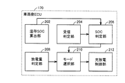
図4に、本実施の形態に係る車両10に搭載された車両側ECU170の機能ブロック図を示す。車両側ECU170は、温存SOC算出部202と、受信判定部204と、SOC判定部206と、放電量判定部208と、モード選択部210と、充放電制御部212とを含む。   FIG. 4 shows a functional block diagram of vehicle-side ECU 170 mounted on vehicle 10 according to the present embodiment. Vehicle-side ECU 170 includes a saved SOC calculation unit 202, a reception determination unit 204, an SOC determination unit 206, a discharge amount determination unit 208, a mode selection unit 210, and a charge / discharge control unit 212.

温存SOC算出部202は、住宅450に電力を供給するために蓄電装置150において温存しておくべきSOC(以下、温存SOCと記載する)を算出する。   Preserved SOC calculation unit 202 calculates SOC that should be stored in power storage device 150 in order to supply power to house 450 (hereinafter referred to as stored SOC).

温存SOC算出部202は、電力要求量のピーク時に蓄電装置150に要求される放電電力(以下、ピーク放電電力と記載する)と、最大使用時間とを乗算することによって、電力のピーク時における必要電力量を算出し、算出された必要電力量を温存SOCとして決定する。温存SOC算出部202は、最大使用電力からエンジン140の発電電力上限値を減算することによってピーク放電電力を算出する。   The saved SOC calculation unit 202 multiplies the discharge power required for the power storage device 150 at the peak power demand amount (hereinafter referred to as peak discharge power) by the maximum usage time, so that it is necessary at the peak power time. The power amount is calculated, and the calculated required power amount is determined as the saved SOC. Preserved SOC calculation section 202 calculates peak discharge power by subtracting the generated power upper limit value of engine 140 from the maximum power consumption.

温存SOC算出部202は、たとえば、メモリ171に記憶される最大使用電力および最大使用時間を用いて温存SOCを算出してもよい。最大使用電力および最大使用時間は、利用者によって入力された値であってもよいし、初期値としてメモリ171に予め記憶された値であってもよい。   The preserved SOC calculation unit 202 may calculate the preserved SOC using, for example, the maximum use power and the maximum use time stored in the memory 171. The maximum power consumption and the maximum usage time may be values input by the user, or may be values stored in advance in the memory 171 as initial values.

あるいは、温存SOC算出部202は、たとえば、過去の電力要求量の履歴に基づいてメモリ171に記憶される最大使用電力および最大使用時間のうちの少なくともいずれか一方を補正してもよい。   Alternatively, the preserved SOC calculation unit 202 may correct at least one of the maximum use power and the maximum use time stored in the memory 171 based on the history of the past power request amount, for example.

温存SOC算出部202は、たとえば、過去の電力要求量の履歴から1日のうちの住宅450の電力要求量がピークとなる回数が最も多い時間帯において過去の数日分の電力要求量のピーク値の平均値を算出して、算出されたピーク値の平均値を用いて最大使用電力を補正してもよい。   The saved SOC calculation unit 202, for example, from the past power request amount history, the peak of the power request amount for the past several days in the time zone where the power request amount of the house 450 in the day is the highest. An average value may be calculated, and the maximum power consumption may be corrected using the calculated average value of the peak values.

温存SOC算出部202は、たとえば、メモリ171に記憶される値と上述のピーク値の平均値とのうちのいずれか大きい方を新たな最大使用電力としてもよい。   For example, the saved SOC calculation unit 202 may use a larger one of the value stored in the memory 171 and the average value of the above-described peak values as a new maximum power consumption.

あるいは、温存SOC算出部202は、たとえば、メモリ171に記憶される値を上述のピーク値の平均値により置き換えるようにしてもよい。   Alternatively, the preserved SOC calculation unit 202 may replace the value stored in the memory 171 with the average value of the above peak values, for example.

あるいは、温存SOC算出部202は、上述のピーク値の平均値からメモリ171に記憶される最大使用電力の値を減算した値に所定係数を乗じて算出される補正値をメモリ171に記憶される最大使用電力の値に加算して新たな最大使用電力を算出してもよい。   Alternatively, the preserved SOC calculation unit 202 stores in the memory 171 a correction value calculated by multiplying a value obtained by subtracting the value of the maximum power used stored in the memory 171 from the average value of the above-described peak values by a predetermined coefficient. A new maximum power consumption may be calculated by adding to the value of the maximum power consumption.

さらに、温存SOC算出部202は、たとえば、電力要求量がピークとなる回数が最も多い時間帯において過去の数日分の電力要求量のピーク値の継続時間の平均値を算出して、算出された継続時間の平均値を用いて最大使用時間を補正してもよい。   Furthermore, the saved SOC calculation unit 202 calculates, for example, an average value of the duration of the peak value of the power request amount for the past several days in the time zone in which the power request amount reaches the maximum number of times. The maximum use time may be corrected using the average value of the continuous durations.

なお、1日の電力要求量のピーク値の継続時間は、たとえば、電力要求量がピーク値よりも所定量だけ低い値を超えた状態が継続する期間をいうものとする。   In addition, the duration of the peak value of the daily power demand amount refers to a period in which the state in which the power demand amount exceeds a value lower than the peak value by a predetermined amount continues, for example.

温存SOC算出部202は、たとえば、メモリ171に記憶される値と上述継続時間の平均値とのうちのいずれか大きい方を新たな最大使用時間としてもよい。   The preserved SOC calculation unit 202 may set, for example, the larger one of the value stored in the memory 171 and the average value of the above duration as the new maximum use time.

あるいは、温存SOC算出部202は、メモリ171に記憶される値を上述の継続時間の平均値により置き換えるようにしてもよい。   Alternatively, the preserved SOC calculation unit 202 may replace the value stored in the memory 171 with the above average value of the duration time.

あるいは、温存SOC算出部202は、上述の継続時間の平均値からメモリ171に記憶される最大使用時間の値を減算した値に所定係数を乗じて算出される補正値をメモリ171に記憶される最大使用時間の値に加算して新たな最大使用時間を算出してもよい。   Alternatively, the saved SOC calculation unit 202 stores in the memory 171 a correction value calculated by multiplying a value obtained by subtracting the value of the maximum usage time stored in the memory 171 from the average value of the above-described duration time. A new maximum usage time may be calculated by adding to the value of the maximum usage time.

温存SOC算出部202は、エンジン140の冷却状態に基づいてエンジン140によって継続して発電できる電力の上限値(以下、発電電力上限値と記載する)を算出する。   Preserved SOC calculation section 202 calculates an upper limit value of power that can be continuously generated by engine 140 based on the cooling state of engine 140 (hereinafter referred to as a generated power upper limit value).

温存SOC算出部202は、たとえば、エンジン140の冷却水温Twに基づいて発電電力上限値を算出する。温存SOC算出部202は、たとえば、冷却水温Twが低い場合の発電電力上限値が冷却水温Twが高い場合の発電電力上限値よりも高くなるように発電電力上限値を算出する。   The saved SOC calculation unit 202 calculates the generated power upper limit value based on the coolant temperature Tw of the engine 140, for example. For example, the saved SOC calculation unit 202 calculates the generated power upper limit value so that the generated power upper limit value when the cooling water temperature Tw is low is higher than the generated power upper limit value when the cooling water temperature Tw is high.

なお、本実施の形態においてはエンジン140の冷却状態として、冷却水温Twを一例としたが特にこれに限定されるものではない。たとえば、温存SOC算出部202は、エンジン140の温度に基づいて発電電力上限値を算出してもよいし、エンジン140の周辺の部品の温度やエンジンルーム内の雰囲気温度に基づいて発電電力上限値を算出してもよい。   In the present embodiment, the cooling water temperature Tw is taken as an example as the cooling state of the engine 140, but is not particularly limited thereto. For example, the saved SOC calculation unit 202 may calculate the generated power upper limit value based on the temperature of the engine 140, or the generated power upper limit value based on the temperature of parts around the engine 140 or the ambient temperature in the engine room. May be calculated.

受信判定部204は、住宅側ECU406から電気負荷416の負荷情報を受信したか否かを判定する。負荷情報は、現在の電気負荷416における負荷量(負荷電力)を含む。なお、受信判定部204は、たとえば、負荷情報を受信した場合に受信判定フラグをオン状態にしてもよい。   The reception determination unit 204 determines whether or not the load information on the electric load 416 has been received from the residential ECU 406. The load information includes the load amount (load power) in the current electric load 416. Note that the reception determination unit 204 may turn on the reception determination flag when, for example, load information is received.

住宅側ECU406は、たとえば、プラグ320とコンセント400とが接続され、コネクタ310とインレット270とが接続された場合に(すなわち、充電ケーブル300が接続状態となった場合に)、電力線通信等の有線通信、あるいは、無線通信により負荷情報を車両側ECU170に送信する。住宅側ECU406は、電気負荷416として含まれる各家庭用電気機器の使用状態あるは設定状態に基づいて電気負荷416の電力の要求量を算出し、算出された電力の要求量を負荷情報として車両側ECU170に送信する。あるいは、住宅側ECU406は、現在の日時に基づいて電力要求量の予測値を決定して、決定された電力要求量の予測値を負荷情報として車両側ECU170に送信してもよい。住宅側ECU406は、たとえば、過去の履歴(負荷量)から現在と同じ時間帯の電力使用量の最大値を電力要求量の予測値として決定し、決定された予測値を負荷情報として車両側ECU170に送信してもよい。   For example, when the plug 320 and the outlet 400 are connected and the connector 310 and the inlet 270 are connected (that is, when the charging cable 300 is in a connected state), the house-side ECU 406 is wired such as power line communication. Load information is transmitted to the vehicle side ECU 170 by communication or wireless communication. The home-side ECU 406 calculates the required amount of electric power for the electric load 416 based on the usage state or the set state of each household electric appliance included as the electric load 416, and the vehicle is used with the calculated required amount of electric power as load information. To the side ECU 170. Alternatively, the house-side ECU 406 may determine a predicted value of the required power amount based on the current date and time and transmit the determined predicted value of the required power amount to the vehicle-side ECU 170 as load information. For example, the home-side ECU 406 determines the maximum value of the power usage amount in the same time zone as the current time from the past history (load amount) as the predicted value of the required power amount, and uses the determined predicted value as the load information. May be sent to.

SOC判定部206は、受信判定部204によって負荷情報が受信された場合に、蓄電装置150の現在のSOCが温存SOCよりも小さいか否かを判定する。なお、SOC判定部206は、たとえば、蓄電装置150の現在のSOCが温存SOCよりも小さい場合に充電要求フラグをオン状態にしてもよい。   The SOC determination unit 206 determines whether or not the current SOC of the power storage device 150 is smaller than the preserved SOC when the load information is received by the reception determination unit 204. For example, SOC determination unit 206 may turn on the charge request flag when the current SOC of power storage device 150 is smaller than the saved SOC.

放電量判定部208は、後述する第1モードおよび第2モードのうちのいずれか一方のモードが選択されており、かつ、車両10から住宅450に対して電力が供給されている場合に、車両10から住宅450への放電量が定格超過状態であるか否かを判定する。   The discharge amount determination unit 208 is a vehicle when either one of a first mode and a second mode, which will be described later, is selected and electric power is supplied from the vehicle 10 to the house 450. It is determined whether the amount of discharge from 10 to the house 450 is in an overrated state.

放電量判定部208は、たとえば、車両10から住宅450への放電電力が定格電力よりも大きく、かつ、定格電力よりも大きい状態が予め定められた時間以上継続する場合に車両10から住宅450への放電量が定格超過状態であると判定する。   The discharge amount determination unit 208, for example, from the vehicle 10 to the house 450 when the discharge power from the vehicle 10 to the house 450 is greater than the rated power and continues to be greater than the rated power for a predetermined time or more. It is determined that the amount of discharge is overrated.

定格電力および予め定められた時間の各々は、MG120およびエンジン140の仕様に基づく発電性能によって設定される値である。定格電力は、上述のエンジン140の発電電力上限値よりも低い値である。たとえば、エンジン140の発電電力上限値が7kWであって、かつ、発電電力上限値で発電を継続できる時間が2秒である場合には、定格電力が6kWとされ、予め定められた時間が1秒とされてもよい。   Each of the rated power and the predetermined time is a value set by the power generation performance based on the specifications of MG 120 and engine 140. The rated power is a value lower than the upper limit value of the generated power of the engine 140 described above. For example, when the upper limit value of the generated power of the engine 140 is 7 kW and the time during which power generation can be continued at the generated power upper limit value is 2 seconds, the rated power is 6 kW, and the predetermined time is 1 It may be a second.

放電量判定部208は、たとえば、車両10からの放電量が定格超過状態であると判定した場合には、放電判定フラグをオン状態にしてもよい。   For example, when the discharge amount determination unit 208 determines that the discharge amount from the vehicle 10 is in an overrated state, the discharge amount determination unit 208 may turn on the discharge determination flag.

また、放電量判定部208は、車両10から住宅450への放電電力が定格電力以下である場合、あるいは、放電電力が定格電力よりも大きい状態の継続時間が予め定められた時間よりも短い場合には、車両10から住宅450への放電量が定格範囲内の状態であると判定する。   Moreover, the discharge amount determination unit 208 is used when the discharge power from the vehicle 10 to the house 450 is equal to or lower than the rated power, or when the duration of the state where the discharge power is larger than the rated power is shorter than a predetermined time. It is determined that the amount of discharge from the vehicle 10 to the house 450 is in the rated range.

モード選択部210は、SOC判定部206および放電量判定部208の判定結果に基づいて、第1モード、第2モードおよび第3モードのうちのいずれか一つのモードを選択する。   The mode selection unit 210 selects any one of the first mode, the second mode, and the third mode based on the determination results of the SOC determination unit 206 and the discharge amount determination unit 208.

第1モードは、図5に示すように、エンジン140を停止させた状態で、蓄電装置150の電力が電気負荷416に供給されるモードである。第1モードが選択された場合には、蓄電装置150の電圧がコンバータ160によって昇圧され、電力変換装置180によって直流電力が交流電力に変換されることによって、蓄電装置150の電力が電気負荷416に供給される。第1モードが選択された場合に、エンジン140が作動状態であると、エンジン140は停止状態になる。   As shown in FIG. 5, the first mode is a mode in which the electric power of the power storage device 150 is supplied to the electric load 416 while the engine 140 is stopped. When the first mode is selected, the voltage of power storage device 150 is boosted by converter 160, and DC power is converted to AC power by power conversion device 180, whereby the power of power storage device 150 is supplied to electric load 416. Supplied. If the first mode is selected and the engine 140 is in an operating state, the engine 140 is stopped.

第2モードは、図6に示すように、エンジン140を作動状態にしてMG120において電力を発電し、発電した電力が蓄電装置150および電気負荷416に供給されるモードである。   As shown in FIG. 6, the second mode is a mode in which power is generated in MG 120 with engine 140 in an operating state, and the generated power is supplied to power storage device 150 and electric load 416.

第2モードが選択された場合には、電力変換装置180によってMG120からの交流電力が直流電圧に変換され、コンバータ160によって蓄電装置150を充電するための電圧(少なくとも蓄電装置150の電圧よりも高い電圧)に変化されることによって蓄電装置150に供給される。   When the second mode is selected, AC power from MG 120 is converted into DC voltage by power conversion device 180, and voltage for charging power storage device 150 by converter 160 (at least higher than the voltage of power storage device 150) Voltage) to be supplied to the power storage device 150.

また、第2モードが選択された場合には、電力変換装置180によってMG120からの3相の交流電力が単相の交流電力に変換されて電気負荷416に供給される。なお、第2モードが選択された場合に、エンジン140が停止状態であると、エンジン140が始動される。   When the second mode is selected, the power converter 180 converts the three-phase AC power from the MG 120 into single-phase AC power and supplies the single-phase AC power to the electric load 416. If the second mode is selected and the engine 140 is in a stopped state, the engine 140 is started.

第3モードは、図7に示すように、エンジン140を作動状態にしてMG120において電力を発電し、発電した電力と、蓄電装置150の電力とが電気負荷416に供給されるモードである。   As shown in FIG. 7, the third mode is a mode in which power is generated in MG 120 with engine 140 in an operating state, and the generated power and the power of power storage device 150 are supplied to electric load 416.

第3モードが選択された場合には、蓄電装置150の電圧がコンバータ160によって昇圧され、電力変換装置180によって直流電力が交流電力に変換されることによって、蓄電装置150の電力が電気負荷416に供給される。   When the third mode is selected, the voltage of power storage device 150 is boosted by converter 160 and the DC power is converted to AC power by power conversion device 180, whereby the power of power storage device 150 is supplied to electric load 416. Supplied.

さらに、第3モードが選択された場合には、電力変換装置180によってMG120からの3相の交流電力が単相の交流電力に変換されて電気負荷416に供給される。なお、第3モードが選択された場合に、エンジン140が停止状態であると、エンジン140が始動される。   Further, when the third mode is selected, the power converter 180 converts the three-phase AC power from the MG 120 into a single-phase AC power and supplies the single-phase AC power to the electric load 416. If the third mode is selected and the engine 140 is in a stopped state, the engine 140 is started.

モード選択部210は、たとえば、SOC判定部206によって現在のSOCが温存SOC以上であると判定された場合には、第1モードを選択する。モード選択部210は、たとえば、SOC判定部206によって現在のSOCが温存SOCよりも小さいと判定された場合には、第2モードを選択する。   For example, when the SOC determination unit 206 determines that the current SOC is equal to or higher than the saved SOC, the mode selection unit 210 selects the first mode. For example, when the SOC determination unit 206 determines that the current SOC is smaller than the preserved SOC, the mode selection unit 210 selects the second mode.

本実施の形態においては、モード選択部210は、現在のSOCが温存SOCよりも小さい場合であって、かつ、強制充電の設定がある場合、あるいは、強制充電の設定がなくても、利用者による充電要求がある場合に第2モードを選択する。利用者は、現在のSOCが温存SOCよりも小さい場合に、自動的に充電を開始する強制充電モードと、利用者の要求に応じて充電を開始する任意充電モードとのうちのいずれか一方を選択できるものとする。利用者によって強制充電モードが選択された場合には、強制充電モードの実行フラグがオン状態にされる。また、利用者によって任意充電モードが選択された場合には、任意充電モードの実行フラグがオンされる。   In the present embodiment, the mode selection unit 210 is a user who is in a case where the current SOC is smaller than the preserving SOC and there is a setting for forced charging, or even if there is no setting for forced charging. The second mode is selected when there is a charging request by. When the current SOC is smaller than the preserved SOC, the user performs either one of a forced charging mode that automatically starts charging or an arbitrary charging mode that starts charging in response to a user request. It shall be selectable. When the forced charging mode is selected by the user, the execution flag for the forced charging mode is turned on. When the arbitrary charging mode is selected by the user, the execution flag for the arbitrary charging mode is turned on.

モード選択部210は、強制充電モードが選択されている場合には、現在のSOCが温存SOCよりも小さい場合には、第2モードを選択する。モード選択部210は、任意充電モードが選択された場合には、通知部178または412等を用いて温存SOCを確保するための充電を行なうか否かの許否の入力を促す通知を利用者に対して行なう。モード選択部210は、利用者により充電を許可する旨の入力を受けた場合に、利用者の充電要求があると判定して、第2モードを選択する。なお、利用者による充電を許可する旨の入力は、たとえば、車両10あるいは住宅450の操作部で受け付けてもよいし、携帯端末等を経由して受け付けてもよい。   When the forced charging mode is selected, the mode selection unit 210 selects the second mode when the current SOC is smaller than the preserved SOC. When the arbitrary charging mode is selected, the mode selection unit 210 uses a notification unit 178 or 412 or the like to notify the user whether or not to charge for securing the preserved SOC. Against. When the mode selection unit 210 receives an input indicating that charging is permitted by the user, the mode selection unit 210 determines that there is a charging request from the user and selects the second mode. It should be noted that the input to permit charging by the user may be received by the operation unit of the vehicle 10 or the house 450, for example, or may be received via a portable terminal or the like.

モード選択部210は、第2モードの選択中において蓄電装置150のSOCが充電完了SOC以上になる場合に第2モードの選択を解除して、第1モードを選択する。充電完了SOCは、温存SOCよりも大きい値であって、満充電状態に対応するSOCの上限値以下の値であれば特に限定されるものではない。   Mode selection unit 210 cancels the selection of the second mode and selects the first mode when the SOC of power storage device 150 is equal to or higher than the charging completion SOC during the selection of the second mode. The charge completion SOC is not particularly limited as long as it is a value larger than the preserving SOC and is equal to or less than the upper limit value of the SOC corresponding to the fully charged state.

さらに、モード選択部210は、第1モードおよび第2モードのうちのいずれか一方のモードが選択されている場合において、放電量判定部208によって車両10から住宅450への放電量が定格超過状態であると判定された場合に、第3モードを選択する。   Furthermore, when one of the first mode and the second mode is selected, the mode selection unit 210 determines that the discharge amount from the vehicle 10 to the house 450 is overrated by the discharge amount determination unit 208. When it is determined that the third mode is selected, the third mode is selected.

さらに、モード選択部210は、第3モードが選択されている場合において、車両10から住宅450への放電量が定格範囲内である場合には、第3モードの選択を解除する。この場合、モード選択部210は、上述したとおり、現在のSOCと温存SOCとに基づいて第1モードおよび第2モードのうちのいずれか一方のモードを選択する。   Furthermore, when the third mode is selected, the mode selection unit 210 cancels the selection of the third mode when the amount of discharge from the vehicle 10 to the house 450 is within the rated range. In this case, as described above, mode selection unit 210 selects one of the first mode and the second mode based on the current SOC and the saved SOC.

モード選択部210は、選択されたモードに対応するフラグをオン状態にする。モード選択部210は、たとえば、第1モードが選択される場合に第1モードフラグをオン状態にする。モード選択部210は、第1モード以外のモードが選択された場合に第1モードフラグをオフ状態にする。   The mode selection unit 210 turns on the flag corresponding to the selected mode. For example, the mode selection unit 210 turns on the first mode flag when the first mode is selected. The mode selection unit 210 turns off the first mode flag when a mode other than the first mode is selected.

モード選択部210は、第2モードが選択される場合に第2モードフラグをオン状態にする。モード選択部210は、第2モード以外のモードが選択された場合に第2モードフラグをオフ状態にする。   The mode selection unit 210 turns on the second mode flag when the second mode is selected. The mode selection unit 210 turns off the second mode flag when a mode other than the second mode is selected.

モード選択部210は、第3モードが選択される場合に第3モードフラグをオン状態にする。モード選択部210は、第3モード以外のモードが選択された場合に第3モードフラグをオフ状態にする。   The mode selection unit 210 turns on the third mode flag when the third mode is selected. The mode selection unit 210 turns the third mode flag off when a mode other than the third mode is selected.

充放電制御部212は、モード選択部210によって選択されたモードに従って電気負荷416の電力要求量に応じた電力を電気負荷416に供給するように車両10を制御する。   The charge / discharge control unit 212 controls the vehicle 10 to supply the electric load 416 with electric power corresponding to the electric power demand amount of the electric load 416 according to the mode selected by the mode selection unit 210.

充放電制御部212は、たとえば、第1モードが選択されている場合には、負荷情報に基づく電気負荷416の電力要求量に応じた電力が電気負荷416に供給されるようにコンバータ160および電力変換装置180を制御する。   For example, when the first mode is selected, the charge / discharge control unit 212 uses the converter 160 and the power so that the electric load 416 is supplied with electric power according to the electric power requirement amount of the electric load 416 based on the load information. The converter 180 is controlled.

充放電制御部212は、第1モードが選択されることによって蓄電装置150の電力を電気負荷416に供給している場合には、蓄電装置150の放電量を調節することによって電力要求量の変動に追従した電力を電気負荷416に供給するようにコンバータ160を制御する。   When the first mode is selected, the charge / discharge control unit 212 supplies the electric load 416 with the electric power of the power storage device 150. The charge / discharge control unit 212 adjusts the discharge amount of the power storage device 150 to change the required power amount. The converter 160 is controlled so as to supply the electric load 416 to the electric load 416.

充放電制御部212は、たとえば、電気負荷416の電力要求量が増加変動する場合には、電力要求量の増加変動前よりも放電量が増加するようにコンバータ160を制御する。充放電制御部212は、たとえば、コンバータ160による蓄電装置150側から電力変換装置180側への昇圧の程度を増加させることによって電力要求量の変動前よりも放電量を増加させる。充放電制御部212は、蓄電装置150から放電量を増加させることによって車両10から電気負荷416に供給される電力を電力要求量の増加変動に追従させることができる。   For example, when the required power amount of electric load 416 increases and changes, charge / discharge control unit 212 controls converter 160 such that the discharge amount increases more than before the increase in required power amount. For example, charging / discharging control unit 212 increases the amount of discharge more than before the fluctuation of the required power amount by increasing the degree of boosting from power storage device 150 side to power conversion device 180 side by converter 160. The charging / discharging control unit 212 can cause the electric power supplied from the vehicle 10 to the electric load 416 to follow the increase fluctuation of the required electric power amount by increasing the discharge amount from the power storage device 150.

さらに、充放電制御部212は、たとえば、電気負荷416の電力要求量が減少変動する場合には、電力要求量の増加変動前よりも放電量が減少するようにコンバータ160を制御する。充放電制御部212は、たとえば、コンバータ160による上述の昇圧の程度を減少させることによって電力要求量の変動前よりも放電量を減少させる。充放電制御部212は、蓄電装置150からの放電量を減少させることによって車両10から電気負荷416に供給される電力を電力要求量の減少変動に追従させることができる。   Further, for example, when the required power amount of electric load 416 decreases and fluctuates, charge / discharge control unit 212 controls converter 160 so that the discharge amount decreases compared to before the increase in power request amount. For example, the charge / discharge control unit 212 reduces the amount of discharge more than before the change in the required power amount by reducing the degree of the above-described boosting by the converter 160. The charge / discharge control unit 212 can cause the electric power supplied from the vehicle 10 to the electric load 416 to follow the decrease in the required electric power amount by decreasing the discharge amount from the power storage device 150.

充放電制御部212は、たとえば、第2モードあるいは第3モードが選択されている場合には、負荷情報に基づく電気負荷416の電力要求量に応じた電力が電気負荷416に供給されるようにエンジン140、コンバータ160および電力変換装置180を制御する。   For example, when the second mode or the third mode is selected, the charge / discharge control unit 212 is configured to supply the electric load 416 with electric power according to the electric power requirement amount of the electric load 416 based on the load information. The engine 140, the converter 160, and the power converter 180 are controlled.

充放電制御部212は、第2モードが選択されることによってMG120の発電電力を蓄電装置150および電気負荷416に供給している場合には、蓄電装置150の充電量を調節することによって電力要求量の変動に追従した電力を電気負荷416に供給するようにコンバータ160を制御する。   When the second mode is selected, the charge / discharge control unit 212 supplies the power generated by the MG 120 to the power storage device 150 and the electric load 416, thereby adjusting the charge amount of the power storage device 150 to request power. The converter 160 is controlled so as to supply the electric load 416 with the electric power following the fluctuation of the amount.

充放電制御部212は、MG120の発電電力が一定になるようにエンジン140を制御する。充放電制御部212は、たとえば、MG120を用いた発電時においてエンジントルクが一定になるようにエンジン140を制御する。   Charging / discharging control unit 212 controls engine 140 so that the power generated by MG 120 is constant. For example, charge / discharge control unit 212 controls engine 140 so that the engine torque is constant during power generation using MG 120.

充放電制御部212は、MG120の発電電力から電力要求量を減算して算出される電力が蓄電装置150の充電電力となるように蓄電装置150の充電量を調節する。   Charging / discharging control unit 212 adjusts the charge amount of power storage device 150 so that the power calculated by subtracting the required power amount from the generated power of MG 120 becomes the charge power of power storage device 150.

充放電制御部212は、たとえば、電気負荷416の電力要求量が増加変動する場合には、電力要求量の増加変動前よりも充電量が減少するようにコンバータ160を制御する。充放電制御部212は、たとえば、コンバータ160による電力変換装置180側から蓄電装置150側への降圧の程度を増加させることによって電力要求量の変動前よりも充電量を減少させる。   Charging / discharging control unit 212 controls converter 160 such that, for example, when the required power amount of electric load 416 increases and changes, the charging amount decreases more than before the increase in required power amount. For example, charging / discharging control unit 212 decreases the amount of charge more than before the fluctuation of the required power amount by increasing the degree of step-down from converter 160 to the power storage device 150 side.

蓄電装置150の充電量を減少させることによって電気負荷416に供給されるMG120からの発電電力を増加させることができる。そのため、車両10から電気負荷416に供給される電力を電力要求量の増加変動に追従させることができる。   By reducing the amount of charge of power storage device 150, the generated power from MG 120 supplied to electric load 416 can be increased. Therefore, the electric power supplied from the vehicle 10 to the electric load 416 can be made to follow the increase fluctuation of the required electric power amount.

充放電制御部212は、たとえば、電気負荷416の電力要求量が減少変動する場合には、電力要求量の減少変動前よりも充電量を増加するようにコンバータ160を制御する。充放電制御部212は、たとえば、コンバータ160による上述の降圧の程度を減少させることによって電力要求量の変動前よりも充電量を増加させる。蓄電装置150の充電量を増加させることによって電気負荷416に供給されるMG120からの発電電力を減少させることができる。そのため、車両10から電気負荷416に供給される電力を電力要求量の減少変動に追従させることができる。   For example, when the required power amount of the electric load 416 decreases and fluctuates, the charge / discharge control unit 212 controls the converter 160 so as to increase the charge amount more than before the decrease in power request amount. For example, the charge / discharge control unit 212 decreases the degree of the above-described step-down by the converter 160 to increase the amount of charge compared to before the change in the required power amount. By increasing the amount of charge of power storage device 150, the generated power from MG 120 supplied to electric load 416 can be reduced. Therefore, the electric power supplied from the vehicle 10 to the electric load 416 can be made to follow the decrease fluctuation of the required power amount.

充放電制御部212は、たとえば、第3モードが選択されることによってMG120の発電電力と蓄電装置150の電力とを電気負荷416に供給している場合には、蓄電装置150の放電量を調節することによって電力要求量の変動に追従した電力を電気負荷416に供給するようにコンバータ160を制御する。   For example, when the third mode is selected, charging / discharging control unit 212 adjusts the discharge amount of power storage device 150 when power generated by MG 120 and power of power storage device 150 are supplied to electric load 416. Thus, the converter 160 is controlled so as to supply the electric load 416 with the electric power following the fluctuation of the electric power requirement.

充放電制御部212は、電力要求量からMG120の発電電力を減算して算出される電力が蓄電装置150の放電電力となるように蓄電装置150の放電量を調節する。   Charging / discharging control unit 212 adjusts the discharge amount of power storage device 150 so that the power calculated by subtracting the generated power of MG 120 from the required power amount becomes the discharge power of power storage device 150.

充放電制御部212は、たとえば、電気負荷416の電力要求量が増加変動する場合には、電力要求量の増加変動前よりも放電量が増加するようにコンバータ160を制御する。充放電制御部212は、たとえば、コンバータ160による上述の昇圧の程度を増加させることによって電力要求量の変動前よりも放電量を増加させる。   For example, when the required power amount of electric load 416 increases and changes, charge / discharge control unit 212 controls converter 160 such that the discharge amount increases more than before the increase in required power amount. For example, the charge / discharge control unit 212 increases the amount of discharge more than before the change in the required power amount by increasing the degree of the above-described boosting by the converter 160.

さらに、充放電制御部212は、たとえば、電気負荷416の電力要求量が減少変動する場合には、電力要求量の減少変動前よりも放電量が減少するようにコンバータ160を制御する。充放電制御部212は、たとえば、コンバータ160による上述の昇圧の程度を減少させることによって電力要求量の変動前よりも放電量を減少させる。   Furthermore, for example, when the required power amount of electric load 416 decreases and varies, charge / discharge control unit 212 controls converter 160 such that the discharge amount is reduced more than before the decrease in required power amount. For example, the charge / discharge control unit 212 reduces the amount of discharge more than before the change in the required power amount by reducing the degree of the above-described boosting by the converter 160.

本実施の形態において、温存SOC算出部202と、受信判定部204と、SOC判定部206と、放電量判定部208と、モード選択部210と、充放電制御部212とは、いずれも車両側ECU170のCPUがメモリ171に記憶されたプログラムを実行することにより実現される、ソフトウェアとして機能するものとして説明するが、ハードウェアにより実現されるようにしてもよい。なお、このようなプログラムは記憶媒体に記録されて車両10に搭載される。   In the present embodiment, preserved SOC calculation unit 202, reception determination unit 204, SOC determination unit 206, discharge amount determination unit 208, mode selection unit 210, and charge / discharge control unit 212 are all vehicle-side. Although the description will be made assuming that the CPU of the ECU 170 functions as software, which is realized by executing a program stored in the memory 171, it may be realized by hardware. Such a program is recorded in a storage medium and mounted on the vehicle 10.

図8を参照して、本実施の形態に係る車両10に搭載された車両側ECU170で実行される、温存SOCを算出するためのプログラムの制御構造について説明する。   With reference to FIG. 8, a control structure of a program for calculating a preserved SOC executed by vehicle-side ECU 170 mounted on vehicle 10 according to the present embodiment will be described.

ステップ(以下、ステップをSと記載する)100にて、車両側ECU170は、温存SOCの算出を開始するか否かを判定する。車両側ECU170は、たとえば、負荷情報を受信した場合に温存SOCの算出を開始すると判定してもよい。あるいは、車両側ECU170は、充電ケーブル300が接続状態となる場合に温存SOCの算出を開始すると判定してもよい。温存SOCの算出を開始する場合(S100にてYES)、処理はS102に移される。もしそうでない場合(S100にてNO)、処理はS100に戻される。   In step (hereinafter, step is referred to as S) 100, vehicle-side ECU 170 determines whether or not to start calculation of the saved SOC. For example, the vehicle-side ECU 170 may determine to start calculating the saved SOC when load information is received. Alternatively, vehicle-side ECU 170 may determine that calculation of the preserved SOC is started when charging cable 300 is in a connected state. If calculation of the saved SOC is started (YES in S100), the process proceeds to S102. If not (NO in S100), the process returns to S100.

S102にて、車両側ECU170は、補正処理を実行して、最大使用電力および最大使用時間を補正する。なお、最大使用電力および最大使用時間の補正については、上述したとおりであるため、その詳細な説明は繰り返さない。   In S102, vehicle-side ECU 170 executes a correction process to correct the maximum use power and the maximum use time. Since the correction of the maximum use power and the maximum use time is as described above, detailed description thereof will not be repeated.

S104にて、車両側ECU170は、エンジン140による発電電力上限値を算出する。車両側ECU170は、エンジン140の冷却水温Twに基づいて発電電力上限値を算出する。   In S104, vehicle-side ECU 170 calculates the upper limit value of power generated by engine 140. The vehicle-side ECU 170 calculates the generated power upper limit value based on the coolant temperature Tw of the engine 140.

S106にて、車両側ECU170は、最大使用電力から発電電力上限値を減算することによってピーク放電電力を算出する。S108にて、車両側ECU170は、ピーク放電電力と最大使用時間とを乗算することによってピーク時の必要電力量を算出する。   In S106, vehicle-side ECU 170 calculates peak discharge power by subtracting the generated power upper limit value from the maximum used power. In S108, vehicle-side ECU 170 calculates the required power amount at the peak time by multiplying the peak discharge power by the maximum usage time.

S110にて、車両側ECU170は、算出された必要電力量を温存SOCとして決定する。   In S110, vehicle-side ECU 170 determines the calculated required power amount as the saved SOC.

次に、図9を参照して、本実施の形態に係る車両10に搭載された車両側ECU170で実行される、現在のSOCに基づいて第1モードまたは第2モードを選択するためのプログラムの制御構造について説明する。   Next, referring to FIG. 9, a program for selecting the first mode or the second mode based on the current SOC, which is executed by vehicle-side ECU 170 mounted on vehicle 10 according to the present embodiment. The control structure will be described.

S200にて、車両側ECU170は、住宅側ECU406から負荷情報を受信したか否かを判定する。負荷情報を受信した場合には(S200にてYES)、処理はS202に移される。もしそうでない場合には(S200にてNO)、処理はS200に戻される。   In S200, vehicle side ECU 170 determines whether or not load information has been received from housing side ECU 406. If load information has been received (YES in S200), the process proceeds to S202. If not (NO in S200), the process returns to S200.

S202にて、車両側ECU170は、蓄電装置150の現在のSOCが温存SOCよりも小さいか否かを判定する。現在のSOCが温存SOCよりも小さい場合には(S202にてYES)、処理はS204に移される。もしそうでない場合には(S202にてNO)、処理はS214に移される。   In S202, vehicle-side ECU 170 determines whether or not the current SOC of power storage device 150 is smaller than the saved SOC. If the current SOC is smaller than the saved SOC (YES in S202), the process proceeds to S204. If not (NO in S202), the process proceeds to S214.

S204にて、車両側ECU170は、強制充電の設定があるか否かを判定する。車両側ECU170は、たとえば、強制充電モードの実行フラグがオン状態である場合に、強制充電の設定があると判定する。強制充電の設定がある場合(S204にてYES)、処理はS208に移される。もしそうでない場合(S204にてNO)、処理はS206に移される。   In S204, vehicle-side ECU 170 determines whether or not forced charging is set. For example, vehicle-side ECU 170 determines that forced charging is set when the execution flag of forced charging mode is on. If forced charging is set (YES in S204), the process proceeds to S208. If not (NO in S204), the process proceeds to S206.

S206にて、車両側ECU170は、利用者の充電要求があるか否かを判定する。車両側ECU170は、たとえば、任意充電モードの実行フラグがオン状態である場合であって、かつ、利用者の充電を許可する旨の入力を受け付けた場合に、利用者の充電要求があると判定する。利用者の充電要求がある場合には(S206にてYES)、処理はS208に移される。もしそうでない場合には(S206にてNO)、処理はS214に移される。   In S206, vehicle-side ECU 170 determines whether or not there is a charging request from the user. The vehicle-side ECU 170 determines that there is a user charge request, for example, when the execution flag of the arbitrary charge mode is on and when an input indicating that the user is allowed to charge is accepted. To do. If there is a user charging request (YES in S206), the process proceeds to S208. If not (NO in S206), the process proceeds to S214.

S208にて、車両側ECU170は、第2モードを選択する。S210にて、車両側ECU170は、充電量制御を実行する。第2モードの選択時における蓄電装置150の充電量の制御については上述したとおりであるため、その詳細な説明は繰り返さない。   In S208, vehicle-side ECU 170 selects the second mode. In S210, vehicle-side ECU 170 executes charge amount control. Since control of the amount of charge of power storage device 150 when selecting the second mode is as described above, detailed description thereof will not be repeated.

S212にて、車両側ECU170は、現在のSOCが充電完了SOC以上であるか否かを判定する。現在のSOCが充電完了SOC以上である場合には(S212にてYES)、処理はS214に移される。もしそうでない場合には(S212にてNO)、処理はS210に戻される。   In S212, vehicle-side ECU 170 determines whether or not the current SOC is equal to or higher than the charging completion SOC. If the current SOC is equal to or higher than the charge completion SOC (YES in S212), the process proceeds to S214. If not (NO in S212), the process returns to S210.

S214にて、車両側ECU170は、第1モードを選択する。S216にて、車両側ECU170は、放電量制御を実行する。第1モードの選択時における蓄電装置150の放電量の制御については上述したとおりであるため、その詳細な説明は繰り返さない。   In S214, vehicle-side ECU 170 selects the first mode. In S216, vehicle-side ECU 170 executes discharge amount control. Since the control of the discharge amount of power storage device 150 when selecting the first mode is as described above, detailed description thereof will not be repeated.

次に、図10を参照して、本実施の形態に係る車両10に搭載された車両側ECU170で実行される、車両からの放電量に基づいて第3モードを選択するためのプログラムの制御構造について説明する。   Next, referring to FIG. 10, a program control structure for selecting the third mode based on the amount of discharge from the vehicle, which is executed by vehicle-side ECU 170 mounted on vehicle 10 according to the present embodiment. Will be described.

S300にて、車両側ECU170は、第1モードおよび第2モードのうちのいずれか一方が選択されているか否かを判定する。第1モードおよび第2モードのうちのいずれか一方が選択されている場合(S300にてYES)、処理はS302に移される。もしそうでない場合(S300にてNO)、処理はS300に戻される。   In S300, vehicle ECU 170 determines whether one of the first mode and the second mode is selected. If either one of the first mode and the second mode is selected (YES in S300), the process proceeds to S302. If not (NO in S300), the process returns to S300.

S302にて、車両側ECU170は、車両10から住宅450への放電量が定格超過状態であるか否かを判定する。放電量が定格超過状態であるか否かの判定方法は、上述したとおりであるため、その詳細な説明は繰り返されない。車両10から住宅450への放電量が定格超過状態である場合(S302にてYES)、処理はS304に移される。もしそうでない場合(S302にてNO)、処理はS300に戻される。   In S302, vehicle-side ECU 170 determines whether or not the amount of discharge from vehicle 10 to house 450 is in an overrated state. Since the method for determining whether or not the discharge amount is in the overrated state is as described above, the detailed description thereof will not be repeated. If the amount of discharge from vehicle 10 to house 450 is in an overrated state (YES in S302), the process proceeds to S304. If not (NO in S302), the process returns to S300.

S304にて、車両側ECU170は、第3モードを選択する。S306にて、車両側ECU170は、放電量制御を実行する。第3モードの選択時における蓄電装置150の放電量の制御については上述したとおりであるため、その詳細な説明は繰り返されない。   In S304, vehicle-side ECU 170 selects the third mode. In S306, vehicle-side ECU 170 executes discharge amount control. Since the control of the discharge amount of power storage device 150 when the third mode is selected is as described above, detailed description thereof will not be repeated.

S308にて、車両側ECU170は、車両10から住宅450への放電量が定格範囲内であるか否かを判定する。放電量が定格範囲内である場合(S308にてYES)、処理はS310に移される。もしそうでない場合(S308にてNO)、処理はS308に戻される。   In S308, vehicle-side ECU 170 determines whether or not the amount of discharge from vehicle 10 to house 450 is within the rated range. If the discharge amount is within the rated range (YES in S308), the process proceeds to S310. If not (NO in S308), the process returns to S308.

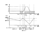
以上のような構造およびフローチャートに基づく本実施の形態に係る車両に搭載された車両側ECU170の動作について図11を参照しつつ説明する。なお、図11に示す斜線の領域は、エンジン140の発電電力が住宅450に供給されていることを示すものとする。   An operation of vehicle-side ECU 170 mounted on the vehicle according to the present embodiment based on the above-described structure and flowchart will be described with reference to FIG. The hatched area shown in FIG. 11 indicates that the electric power generated by the engine 140 is supplied to the house 450.

たとえば、充電ケーブル300が接続状態となる場合に(S100にてYES)、最大使用電力および最大使用時間の補正処理が実行され(S102)、エンジン140の発電電力上限値が算出される(S106)。補正された最大使用電力から算出された発電電力上限値が減算されてピーク放電電力が算出される(S106)。   For example, when charging cable 300 is in a connected state (YES in S100), correction processing for maximum power consumption and maximum usage time is executed (S102), and the generated power upper limit value of engine 140 is calculated (S106). . The peak discharge power is calculated by subtracting the generated power upper limit value calculated from the corrected maximum power consumption (S106).

算出されたピーク放電電力と最大使用時間とが乗算されてピーク時における必要電力量が算出され(S108)、残存SOCが算出される(S110)。   The calculated peak discharge power and the maximum usage time are multiplied to calculate the required power amount at the peak time (S108), and the remaining SOC is calculated (S110).

負荷量がLbであることを示す負荷情報を受信した場合に(S200にてYES)、現在のSOCが温存SOCより大きい場合には(S202にてYES)、第1モードが選択され(S214)、放電量制御が実行される(S216)。   When load information indicating that the load amount is Lb is received (YES in S200), if the current SOC is greater than the saved SOC (YES in S202), the first mode is selected (S214). Then, the discharge amount control is executed (S216).

図11に示すように、時間の経過とともに電気負荷416にて電力が消費されるため、蓄電装置150のSOCは、低下していくこととなる。時間T(0)にて、蓄電装置150のSOCが温存SOCよりも小さくなる場合には(S202にてYES)、強制充電の設定がある場合(S204にてYES)、あるいは、強制充電の設定がなくても(S204にてNO)、利用者の充電要求がある場合(S206にてYES)、第2モードが選択され(S208)、充電量制御が実行される(S210)。   As shown in FIG. 11, since electric power is consumed by the electric load 416 as time passes, the SOC of the power storage device 150 decreases. If the SOC of power storage device 150 is smaller than the saved SOC at time T (0) (YES in S202), if forced charging is set (YES in S204), or forced charging is set Even if there is no (NO in S204), if there is a charge request from the user (YES in S206), the second mode is selected (S208), and the charge amount control is executed (S210).

第2モードが選択されることによってエンジン140が作動状態となり、MG120における発電電力が蓄電装置150および電気負荷416に供給される。そのため、図11の斜線の領域に示されるように、エンジン140による発電電力の一部が電気負荷416に供給され、発電電力の残部が蓄電装置150の充電に用いられることとなる。そのため、蓄電装置150のSOCは、時間T(0)以降、時間が経過するとともに増加していく。   By selecting the second mode, engine 140 is activated, and the generated power in MG 120 is supplied to power storage device 150 and electric load 416. Therefore, as indicated by the hatched area in FIG. 11, part of the power generated by engine 140 is supplied to electric load 416, and the remainder of the generated power is used for charging power storage device 150. Therefore, the SOC of power storage device 150 increases with time after time T (0).

時間T(1)にて、蓄電装置150のSOCが充電完了SOC以上となる場合に(S212にてYES)、第2モードの選択が解除され、第1モードが選択され(S214)、放電量制御が実行される(S216)。このとき、エンジン140は、再び停止状態になる。そのため、蓄電装置150は充電から放電に切り替わり、蓄電装置150の電力が電気負荷416に供給されることとなる。   If the SOC of power storage device 150 is equal to or higher than the charge completion SOC at time T (1) (YES in S212), the selection of the second mode is canceled, the first mode is selected (S214), and the amount of discharge Control is executed (S216). At this time, the engine 140 is stopped again. Therefore, the power storage device 150 is switched from charging to discharging, and the power of the power storage device 150 is supplied to the electric load 416.

時間T(2)にて、電気負荷416として含まれる住宅450内の電気機器の作動量が増加したり、あるいは、作動状態の電気機器の数が増加したりした場合には、負荷量が大きく増加する。   At time T (2), if the amount of operation of the electric devices in the house 450 included as the electric load 416 increases or the number of electric devices in operation increases, the load amount increases. To increase.

電力要求量が増加側に変動した場合には、蓄電装置150の放電量が増加することによって、電力要求量の増加変動に追従した電力が電気負荷416に供給されることになる。   When the required power amount fluctuates to the increasing side, the amount of discharge of the power storage device 150 increases, so that the electric power following the increase fluctuation of the required power amount is supplied to the electric load 416.

時間T(3)にて、第1モードの選択中であって(S300にてYES)、かつ、車両10から住宅450への放電量が定格超過状態になる場合(S302にてYES)、第3モードが選択され(S304)、放電量制御が実行される(S306)。   At time T (3), when the first mode is being selected (YES in S300) and the amount of discharge from vehicle 10 to house 450 becomes overrated (YES in S302), Three modes are selected (S304), and discharge amount control is executed (S306).

第3モードが選択されることによってエンジン140が作動状態となる。そのため、電気負荷416には、MG120において発電された電力と蓄電装置150の電力とが供給される。エンジントルクが一定になるようにエンジン140が制御される。そのため、MG120において一定の発電電力が発生する。本実施の形態においては、説明の便宜上、電力Lbを発電するものとして説明するが、特にこれに限定されるものではない。   By selecting the third mode, the engine 140 is in an operating state. Therefore, the electric load 416 is supplied with the power generated in MG 120 and the power of power storage device 150. The engine 140 is controlled so that the engine torque is constant. Therefore, a certain amount of generated power is generated in MG 120. In the present embodiment, for convenience of explanation, the description will be made assuming that the power Lb is generated, but the present invention is not particularly limited thereto.

時間T(3)以降においては、一定の発電電力Lbが発生するとともに、増加側に変動する電力要求量に対しては蓄電装置150の放電量を増加させることによって、電力要求量の変動に追従した電力が電気負荷416に供給されることになる。すなわち、電力要求量のうち発電電力Lbを減算した電力が蓄電装置150から供給されるように蓄電装置150の放電量が増加される。   After time T (3), a certain amount of generated power Lb is generated, and the amount of electric power demand that fluctuates to the increasing side is tracked by increasing the amount of discharge of power storage device 150 to follow the variation in power demand. The electric power thus supplied is supplied to the electric load 416. That is, the amount of discharge of power storage device 150 is increased so that power obtained by subtracting generated power Lb from the power demand amount is supplied from power storage device 150.

蓄電装置150のSOCは、電気負荷416への電力の供給により時間の経過とともに減少していく。時間T(4)にて、車両10から住宅450への放電量が定格範囲内となる場合(S308にてYES)、第3モードの選択が解除される(S310)。   The SOC of the power storage device 150 decreases with the passage of time due to the supply of electric power to the electric load 416. If the amount of discharge from vehicle 10 to house 450 falls within the rated range at time T (4) (YES in S308), the selection of the third mode is canceled (S310).

蓄電装置150のSOCが温存SOCよりも小さいため(S202にてYES)、強制充電の設定がある場合(S204にてYES)、あるいは、強制充電の設定がなくても、利用者の充電要求がある場合(S206にてYES)、第2モードが選択され(S208)、充電量制御が実行される(S210)。   Since SOC of power storage device 150 is smaller than the preserving SOC (YES in S202), if there is a forced charge setting (YES in S204), or even if there is no forced charge setting, the user's charge request is If present (YES in S206), the second mode is selected (S208), and the charge amount control is executed (S210).

蓄電装置150の充電により、蓄電装置150のSOCは、時間T(4)以降、時間が経過するとともに増加していくこととなる。   As the power storage device 150 is charged, the SOC of the power storage device 150 increases with time after the time T (4).

時間T(5)にて、蓄電装置150のSOCが充電完了SOC以上になる場合(S212にてYES)、第1モードが選択され(S214)、放電量制御が実行される(S216)。   If the SOC of power storage device 150 becomes equal to or higher than the charge completion SOC at time T (5) (YES in S212), the first mode is selected (S214), and the discharge amount control is executed (S216).

以上のようにして、本実施の形態に係る車両によると、蓄電装置150のSOCが温存SOCよりも低い場合に第2モードを選択して、蓄電装置150を充電した後に住宅450に電力を供給する。これにより、住宅450が要求する電力が増加した場合でも電力を蓄電装置150とエンジン140とを用いて住宅450の電力要求量の変動に追従した受電設備に供給することができる。したがって、車両外部からの車載バッテリの放電能力を超える電力要求を満足させるための車両および車両用制御方法を提供することができる。   As described above, according to the vehicle according to the present embodiment, when SOC of power storage device 150 is lower than the saved SOC, the second mode is selected, and power is supplied to house 450 after power storage device 150 is charged. To do. Thereby, even when the electric power required by the house 450 increases, the electric power can be supplied to the power receiving facility that follows the fluctuation of the electric power required amount of the house 450 using the power storage device 150 and the engine 140. Therefore, it is possible to provide a vehicle and a vehicle control method for satisfying a power requirement exceeding the discharge capacity of the in-vehicle battery from the outside of the vehicle.

本実施の形態においては、蓄電装置150のSOCが温存SOCよりも小さい場合に、強制的に充電する強制充電モードと、利用者の充電要求の有無を確認する任意充電モードとのうちのいずれかのモードを選択することができる。そのため、運転者が意図せずにエンジン140が始動することを抑制することができる。   In the present embodiment, when the SOC of power storage device 150 is smaller than the preserving SOC, one of a forced charging mode for forcibly charging and an arbitrary charging mode for confirming whether or not a user has requested charging is selected. Mode can be selected. Therefore, it is possible to prevent the engine 140 from starting unintentionally by the driver.

蓄電装置の充放電量を調節することによって電力要求量の変動に追従した電力を住宅450に供給することによって、エンジン140を用いて発電電力を一定にすることができる。そのため、効率良く発電を行なうことができる。   By supplying the house 450 with the electric power that follows the fluctuation of the required electric power by adjusting the charge / discharge amount of the power storage device, the generated electric power can be made constant using the engine 140. Therefore, power generation can be performed efficiently.

さらに、エンジン140の冷却水温Twに応じて発電電力上限値を算出することによって適切な発電電力で発電を行なうことができる。   Furthermore, it is possible to generate power with appropriate generated power by calculating the generated power upper limit value according to the cooling water temperature Tw of the engine 140.

本実施の形態においては、放電量が定格超過状態であるか否かは、エンジン140の発電電力上限値を基準として設定された定格電力により判定するものとして説明するが、たとえば、第1モードが選択されている場合と、第2モードが選択されている場合とで定格電力を変更するようにしてもよい。   In the present embodiment, it is described that whether or not the discharge amount is in an overrated state is determined based on the rated power set on the basis of the generated power upper limit value of engine 140. For example, in the first mode, The rated power may be changed between when it is selected and when the second mode is selected.

今回開示された実施の形態はすべての点で例示であって制限的なものではないと考えられるべきである。本発明の範囲は上記した説明ではなくて特許請求の範囲によって示され、特許請求の範囲と均等の意味および範囲内でのすべての変更が含まれることが意図される。   The embodiment disclosed this time should be considered as illustrative in all points and not restrictive. The scope of the present invention is defined by the terms of the claims, rather than the description above, and is intended to include any modifications within the scope and meaning equivalent to the terms of the claims.

1 充放電システム、10 車両、20 駆動部、470 スタンド、130 駆動輪、140 エンジン、145 動力分割機構、150 蓄電装置、160 コンバータ、162 平滑コンデンサ、171,407 メモリ、172,404 PLC装置、174,408 無線通信装置、178,412 通知部、180 電力変換装置、182,604,650 電圧センサ、202 温存SOC算出部、204 受信判定部、206 SOC判定部、208 放電量判定部、210 モード選択部、212 充放電制御部、241,341,441,ACL1,ACL2 電力線、270 インレット、300 充電ケーブル、310 コネクタ、312 接続検出回路、320 プラグ、332 リレー、334 コントロールパイロット回路、340 電線部、400 コンセント、402 系統電源、414 切替部、416 電気負荷、418 主幹ブレーカ、420,422,424,426 分岐ブレーカ、428 ブレーカ、430 トランス、432 第1リレー、434 第2リレー、450 住宅、460 分電盤、502 抵抗回路、504,506 入力バッファ、511 電源ノード、512 車両アース、602 発振装置、606 電磁コイル、608 漏電検出器、610 制御部、660 電流センサ。   1 Charging / Discharging System, 10 Vehicle, 20 Drive Unit, 470 Stand, 130 Drive Wheel, 140 Engine, 145 Power Dividing Mechanism, 150 Power Storage Device, 160 Converter, 162 Smoothing Capacitor, 171, 407 Memory, 172, 404 PLC Device, 174 408 Wireless communication device 178 412 Notification unit 180 Power converter 182 604 650 Voltage sensor 202 Preserved SOC calculation unit 204 Reception determination unit 206 SOC determination unit 208 Discharge amount determination unit 210 Mode selection Part, 212 charge / discharge control part, 241, 341, 441, ACL1, ACL2 power line, 270 inlet, 300 charging cable, 310 connector, 312 connection detection circuit, 320 plug, 332 relay, 334 control pilot circuit, 34 Electric wire part, 400 outlet, 402 system power supply, 414 switching part, 416 electrical load, 418 trunk breaker, 420, 422, 424, 426 branch breaker, 428 breaker, 430 transformer, 432 first relay, 434 second relay, 450 house 460 distribution board, 502 resistance circuit, 504, 506 input buffer, 511 power supply node, 512 vehicle ground, 602 oscillator, 606 electromagnetic coil, 608 leakage detector, 610 control unit, 660 current sensor.

Claims (6)

車両の外部の受電設備への電力の供給が可能な蓄電装置と、
エンジンを動力源として前記蓄電装置および前記受電設備への電力の供給が可能な発電装置と、
前記発電装置および前記蓄電装置のうちの少なくともいずれか一方から電力を前記受電設備に供給するように前記車両を制御するための制御装置とを含み、
前記制御装置は、前記受電設備から電力の供給が要求された場合に前記蓄電装置の残容量がしきい値よりも小さいときには、前記発電装置を用いて前記蓄電装置を充電した後に前記蓄電装置および前記発電装置を用いて前記受電設備に電力を供給するように前記車両を制御する、車両。
A power storage device capable of supplying power to a power receiving facility outside the vehicle;
A power generation device capable of supplying power to the power storage device and the power receiving facility using an engine as a power source;
A control device for controlling the vehicle so as to supply power from at least one of the power generation device and the power storage device to the power receiving facility,
When the remaining capacity of the power storage device is smaller than a threshold when power supply is requested from the power receiving facility, the control device uses the power generation device to charge the power storage device and A vehicle that controls the vehicle to supply power to the power receiving facility using the power generation device.
前記制御装置は、前記蓄電装置の前記残容量が前記しきい値よりも小さい場合に強制的に前記蓄電装置を充電する第1充電モードと、前記蓄電装置の前記残容量が前記しきい値よりも小さい場合に利用者の要求に応じて前記蓄電装置を充電する第2充電モードとのうちのいずれか一方の充電モードに従って前記蓄電装置を充電するように前記車両を制御する、請求項1に記載の車両。   The control device includes: a first charging mode for forcibly charging the power storage device when the remaining capacity of the power storage device is smaller than the threshold; and the remaining capacity of the power storage device from the threshold The vehicle is controlled to charge the power storage device according to any one of a second charging mode and a second charging mode for charging the power storage device in response to a user request when The vehicle described. 前記制御装置は、前記発電装置の発電および前記蓄電装置の放電により前記受電設備の電力要求量に応じた電力を前記受電設備に供給するように前記車両を制御し、前記受電設備の前記電力要求量がしきい値よりも大きくなる場合には、前記蓄電装置の放電量を調節することによって前記電力要求量の変動に追従した電力を前記受電設備に供給するように前記車両を制御する、請求項1または2に記載の車両。   The control device controls the vehicle to supply the power receiving facility with power corresponding to a power requirement of the power receiving facility by power generation of the power generation device and discharge of the power storage device, and the power request of the power receiving facility. When the amount becomes larger than a threshold value, the vehicle is controlled so as to supply the power receiving equipment with power following the variation in the required power amount by adjusting a discharge amount of the power storage device. Item 3. The vehicle according to Item 1 or 2. 前記制御装置は、前記エンジンの冷却状態に応じて発電電力の上限値を決定する、請求項1〜3のいずれかに記載の車両。   The vehicle according to any one of claims 1 to 3, wherein the control device determines an upper limit value of the generated power in accordance with a cooling state of the engine. 前記制御装置は、前記発電装置による発電電力が一定になるように前記エンジンを制御する、請求項1〜4のいずれかに記載の車両。   The vehicle according to claim 1, wherein the control device controls the engine so that power generated by the power generation device is constant. 車両の外部の受電設備への電力の供給が可能な蓄電装置と、エンジンを動力源として前記蓄電装置および前記受電設備への電力の供給が可能な発電装置とを搭載した前記車両に用いられる車両用制御方法であって、
前記受電設備から電力の供給が要求された場合に前記蓄電装置の残容量がしきい値よりも小さいときには、前記発電装置を用いて前記蓄電装置を充電するステップと、
前記発電装置を用いて前記蓄電装置を充電した後に前記蓄電装置および前記発電装置を用いて前記受電設備に電力を供給するように前記車両を制御するステップとを含む、車両用制御方法。
A vehicle used in the vehicle including a power storage device capable of supplying power to a power receiving facility outside the vehicle, and a power generation device capable of supplying power to the power storage device and the power receiving facility using an engine as a power source Control method for
Charging the power storage device using the power generation device when the remaining capacity of the power storage device is smaller than a threshold when power supply is requested from the power receiving facility;
And controlling the vehicle to supply power to the power receiving facility using the power storage device and the power generation device after charging the power storage device using the power generation device.
JP2012053194A 2012-03-09 2012-03-09 Vehicle and vehicle control method Active JP5831304B2 (en)

Priority Applications (1)

Application Number Priority Date Filing Date Title
JP2012053194A JP5831304B2 (en) 2012-03-09 2012-03-09 Vehicle and vehicle control method

Applications Claiming Priority (1)

Application Number Priority Date Filing Date Title
JP2012053194A JP5831304B2 (en) 2012-03-09 2012-03-09 Vehicle and vehicle control method

Publications (2)

Publication Number Publication Date
JP2013184643A true JP2013184643A (en) 2013-09-19
JP5831304B2 JP5831304B2 (en) 2015-12-09

Family

ID=49386455

Family Applications (1)

Application Number Title Priority Date Filing Date
JP2012053194A Active JP5831304B2 (en) 2012-03-09 2012-03-09 Vehicle and vehicle control method

Country Status (1)

Country Link
JP (1) JP5831304B2 (en)

Cited By (3)

* Cited by examiner, † Cited by third party
Publication number Priority date Publication date Assignee Title
JP2017040178A (en) * 2015-08-18 2017-02-23 三菱自動車工業株式会社 Control device of hybrid automobile
JP2020145796A (en) * 2019-03-05 2020-09-10 東京電力ホールディングス株式会社 On-vehicle control device, on-vehicle control program and electric power supply system
CN112154087A (en) * 2018-05-22 2020-12-29 本田技研工业株式会社 Electric vehicle and electric vehicle control method

Citations (7)

* Cited by examiner, † Cited by third party
Publication number Priority date Publication date Assignee Title
JPH07131905A (en) * 1993-11-04 1995-05-19 Honda Motor Co Ltd Hybrid power source for electric vehicle
JPH08168103A (en) * 1994-12-12 1996-06-25 Toyota Motor Corp Hybrid electric automobile
JP2000234539A (en) * 1998-12-15 2000-08-29 Toyota Motor Corp Control device for hybrid vehicle
JP2001041073A (en) * 1999-07-28 2001-02-13 Toyota Motor Corp Vehicle control device
JP2004236472A (en) * 2003-01-31 2004-08-19 Toyota Motor Corp Controller of vehicle
JP2004257293A (en) * 2003-02-25 2004-09-16 Yanmar Co Ltd Hybrid system
JP2006132391A (en) * 2004-11-04 2006-05-25 Mitsubishi Fuso Truck & Bus Corp Control device of series type hybrid vehicle

Patent Citations (7)

* Cited by examiner, † Cited by third party
Publication number Priority date Publication date Assignee Title
JPH07131905A (en) * 1993-11-04 1995-05-19 Honda Motor Co Ltd Hybrid power source for electric vehicle
JPH08168103A (en) * 1994-12-12 1996-06-25 Toyota Motor Corp Hybrid electric automobile
JP2000234539A (en) * 1998-12-15 2000-08-29 Toyota Motor Corp Control device for hybrid vehicle
JP2001041073A (en) * 1999-07-28 2001-02-13 Toyota Motor Corp Vehicle control device
JP2004236472A (en) * 2003-01-31 2004-08-19 Toyota Motor Corp Controller of vehicle
JP2004257293A (en) * 2003-02-25 2004-09-16 Yanmar Co Ltd Hybrid system
JP2006132391A (en) * 2004-11-04 2006-05-25 Mitsubishi Fuso Truck & Bus Corp Control device of series type hybrid vehicle

Cited By (4)

* Cited by examiner, † Cited by third party
Publication number Priority date Publication date Assignee Title
JP2017040178A (en) * 2015-08-18 2017-02-23 三菱自動車工業株式会社 Control device of hybrid automobile
CN112154087A (en) * 2018-05-22 2020-12-29 本田技研工业株式会社 Electric vehicle and electric vehicle control method
CN112154087B (en) * 2018-05-22 2024-03-08 本田技研工业株式会社 Electric vehicle and electric vehicle control method
JP2020145796A (en) * 2019-03-05 2020-09-10 東京電力ホールディングス株式会社 On-vehicle control device, on-vehicle control program and electric power supply system

Also Published As

Publication number Publication date
JP5831304B2 (en) 2015-12-09

Similar Documents

Publication Publication Date Title
EP2783899B1 (en) Charging system and charging reservation method
JP6015038B2 (en) Vehicle and vehicle control method
JP5710775B2 (en) Vehicle charging system and vehicle charging method
US9160184B2 (en) Adapter and vehicle equipped therewith, and method for controlling the vehicle
US9216655B2 (en) Vehicle and power supply system
US9431688B2 (en) Method for heating a high voltage vehicle battery
JP6156484B2 (en) vehicle
JP5880582B2 (en) vehicle
JP5561441B2 (en) Vehicle, vehicle control method, and power receiving equipment
US20130088198A1 (en) Electric charging system and electric charging method
US8502411B2 (en) Power limiting apparatus for electric system, power limiting method for electric system and electric system
WO2012056516A1 (en) Power supply device, vehicle provided with same, and power supply method
JP2010110101A (en) Battery remaining amount monitoring system
WO2011145192A1 (en) Charger control device, and charging device
JP2011259658A (en) Vehicular charging system and motor-driven vehicle
JP5831304B2 (en) Vehicle and vehicle control method
WO2012059988A1 (en) Charging device and vehicle employing same
WO2019064252A2 (en) Home charging and power backup unit
JP2015139325A (en) power supply control device
JPWO2013080272A1 (en) Charging system and charging reservation method

Legal Events

Date Code Title Description
A621 Written request for application examination

Free format text: JAPANESE INTERMEDIATE CODE: A621

Effective date: 20140226

A977 Report on retrieval

Free format text: JAPANESE INTERMEDIATE CODE: A971007

Effective date: 20150406

A131 Notification of reasons for refusal

Free format text: JAPANESE INTERMEDIATE CODE: A131

Effective date: 20150414

A521 Written amendment

Free format text: JAPANESE INTERMEDIATE CODE: A523

Effective date: 20150428

TRDD Decision of grant or rejection written
A01 Written decision to grant a patent or to grant a registration (utility model)

Free format text: JAPANESE INTERMEDIATE CODE: A01

Effective date: 20150929

A61 First payment of annual fees (during grant procedure)

Free format text: JAPANESE INTERMEDIATE CODE: A61

Effective date: 20151012

R151 Written notification of patent or utility model registration

Ref document number: 5831304

Country of ref document: JP

Free format text: JAPANESE INTERMEDIATE CODE: R151