JP2013183306A - Imaging apparatus, imaging method, and program - Google Patents
Imaging apparatus, imaging method, and program Download PDFInfo
- Publication number
- JP2013183306A JP2013183306A JP2012046039A JP2012046039A JP2013183306A JP 2013183306 A JP2013183306 A JP 2013183306A JP 2012046039 A JP2012046039 A JP 2012046039A JP 2012046039 A JP2012046039 A JP 2012046039A JP 2013183306 A JP2013183306 A JP 2013183306A
- Authority
- JP
- Japan
- Prior art keywords
- composition
- image
- frame
- photographing
- unit
- Prior art date
- Legal status (The legal status is an assumption and is not a legal conclusion. Google has not performed a legal analysis and makes no representation as to the accuracy of the status listed.)
- Pending
Links
Images


Abstract
Description
本発明は、撮像装置、撮像方法、及びプログラムに関する。 The present invention relates to an imaging apparatus, an imaging method, and a program.
一般的に、良い写真を撮影するためには、焦点を合わせる、露出を合わせる、ブレを無くす、色を補正する、より所望する構図で撮影する等が必要とされているが、これらの中でより所望する構図で撮影することに関する技術だけが自動化で遅れている。 In general, in order to take a good picture, it is necessary to adjust the focus, adjust the exposure, eliminate blurring, correct the color, shoot with a desired composition, etc. Only technology related to shooting with a more desired composition is delayed by automation.
例えば、特許文献1には、撮影後に保存された撮影画像から主要被写体の位置を検出し、該主要被写体を配した複数のトリミング画像を生成し、操作者より複数のトリミング画像から所望する1つの画像を選択させる技術が開示されている。 For example, in Patent Document 1, the position of a main subject is detected from a captured image stored after shooting, a plurality of trimmed images in which the main subject is arranged are generated, and a desired one from a plurality of trimmed images by an operator is generated. A technique for selecting an image is disclosed.
また、特許文献2には、ライブ画像をそのままの画角で撮影し、顔検出した位置でのみ構図を判定する技術が開示されている。 Japanese Patent Application Laid-Open No. 2004-228688 discloses a technique for capturing a live image at an angle of view as it is and determining the composition only at the face detection position.
また、特許文献3には、スルー画像から抽出した被写体と、背景と被写体との配置が予め設定されている構図アシスト用のフレーム内の被写体との位置がずれている場合にカメラの移動方向を指示し、双方の位置が合致すると、合致したことを通知するとともに、合致状態が所定時間経過すると撮像する技術が開示されている。 Japanese Patent Laid-Open No. 2004-26883 discloses a camera movement direction when the subject extracted from the through image and the subject in the frame for composition assistance in which the arrangement of the background and the subject is preset are shifted. A technique is disclosed in which an instruction is given and notification is made when both positions match, and an image is picked up when the matching state has passed for a predetermined time.
また、特許文献4には、ライブビュー表示でフレーム枠の大きさと位置を設定し、該フレーム枠の大きさと位置とに対応する撮影画像の一部を選択画像として保持し、該選択画像とスルー画像とが一致するように、ズーミングの調節や撮影方向を移動させることで、所望する構図、画角での撮影を行う技術が開示されている。
In
しかしながら、特許文献1では、操作が複雑になってしまうという問題があるとともに、撮影時に撮影範囲が決まっているため、撮影画像の周囲も含めたほうが、構図が良くなるような場合でも、自由に構図を決めることができないという問題があった。 However, in Patent Document 1, there is a problem that the operation becomes complicated, and the shooting range is determined at the time of shooting. Therefore, including the periphery of the shot image is free even when the composition is improved. There was a problem that the composition could not be determined.
また、特許文献2では、ライブ画像をそのままの画角で撮影画像として記録するため、所望する構図になるように試行錯誤して撮像装置を構える必要があるという問題があった。さらに、顔検出した位置でのみ構図を判定するため、顔の無いシーンの撮影では、構図が決まらないという問題があった。
Further, in
また、特許文献3では、構図アシスト用のフレーム内に設定された被写体位置に撮影している被写体を合わせる必要があり、自由に構図を決めることができないという問題があった。 Further, in Patent Document 3, there is a problem that it is necessary to match the subject being photographed with the subject position set in the composition assist frame, and the composition cannot be determined freely.
また、特許文献4では、構図や画角はユーザが設定しなければならず、操作が複雑になってしまうという問題があるとともに、所望する構図になるように試行錯誤して操作しなければならないという問題があった。
Further, in
そこで本発明は、操作を煩雑にすることなく、より容易に撮影時の構図を決めることができる撮像装置、撮像方法、及びプログラムを提供することを目的とする。 SUMMARY An advantage of some aspects of the invention is that it provides an imaging apparatus, an imaging method, and a program that can more easily determine the composition at the time of shooting without complicating the operation.
本発明の撮像装置は、画像を取り込む撮影手段と、前記撮影手段によって取り込まれた画像に基づいて、所定の構図条件を満足する構図となる撮影範囲を求める撮影範囲算出手段と、前記所定の構図条件を満足する構図となる撮影範囲を、前記撮影手段により取り込まれた画像上に重ねて合成した構図ガイド画像を生成する構図ガイド生成手段と、前記構図ガイド画像を表示する表示手段とを備えることを特徴とする撮像装置である。 The imaging apparatus according to the present invention includes a photographing unit that captures an image, a photographing range calculating unit that obtains a photographing range that satisfies a predetermined composition condition based on the image captured by the photographing unit, and the predetermined composition. A composition guide generating unit that generates a composition guide image obtained by superimposing an image capturing range that satisfies a condition on an image captured by the image capturing unit; and a display unit that displays the composition guide image. An imaging device characterized by the above.
本発明の撮像方法は、撮像素子によって画像を取り込む撮影ステップと、前記撮影ステップで取り込まれた前記画像に基づいて、所定の構図条件を満足する構図となる撮影範囲を求める撮影範囲算出ステップと、前記所定の構図条件を満足する構図となる撮影範囲を、前記撮影ステップで取り込まれた前記画像上に重ねて合成した構図ガイド画像を生成する構図ガイド生成ステップと、前記構図ガイド画像を表示する表示ステップとを含むことを特徴とする撮像方法である。 The imaging method of the present invention includes a shooting step for capturing an image with an image sensor, and a shooting range calculation step for obtaining a shooting range having a composition that satisfies a predetermined composition condition based on the image captured in the shooting step. A composition guide generating step for generating a composition guide image obtained by superimposing the image capturing range that satisfies the predetermined composition condition on the image captured in the image capturing step, and a display for displaying the composition guide image An imaging method comprising: steps.
本発明のプログラムは、撮像装置のコンピュータに、撮像素子によって画像を取り込む撮影機能、前記撮影機能で取り込まれた前記画像に基づいて、所定の構図条件を満足する構図となる撮影範囲を求める撮影範囲算出機能、前記所定の構図条件を満足する構図となる撮影範囲を、前記撮影ステップで取り込まれた前記画像上に重ねて合成した構図ガイド画像を生成する構図ガイド生成機能、前記構図ガイド画像を表示する表示機能を実行させることを特徴とするプログラムである。 The program according to the present invention includes a photographing function for capturing an image with an image sensor in a computer of an imaging device, and a photographing range for obtaining a photographing range that satisfies a predetermined composition condition based on the image captured by the photographing function. A calculation function; a composition guide generation function for generating a composition guide image by superimposing a photographing range that satisfies the predetermined composition condition on the image captured in the photographing step; and displaying the composition guide image A program characterized by causing a display function to be executed.
この発明によれば、操作を煩雑にすることなく、より容易に撮影時の構図を決めることができる。 According to the present invention, the composition at the time of photographing can be determined more easily without complicating the operation.
以下、本発明の実施の形態を、図面を参照して説明する。 Hereinafter, embodiments of the present invention will be described with reference to the drawings.
図1は、本発明の実施形態による撮像装置1の構成を示すブロック図である。図において、撮像装置1は、光学部2、制御部3、表示部4、入力部5、及び記憶部6から構成されている。光学部2は、フォーカスレンズやズームレンズ等からなるレンズ7と、CMOSセンサやCCD等の撮像素子8とから構成されている。撮像素子8は、レンズ7を通して結像した光を電気信号に変換して画像データとして出力する。
FIG. 1 is a block diagram illustrating a configuration of an imaging apparatus 1 according to an embodiment of the present invention. In the figure, the imaging device 1 includes an
制御部3は、光学部2の制御と画像処理を行う画像処理部10、制御部3内の各部を統括的に制御するCPUやDSP等の演算部11、プログラムやデータを保存するDRAM等の主記憶部12、表示部4の表示動作を制御する表示制御部13、入力部5を制御する入力制御部14、記憶部6を制御する記憶制御部15からなる。
The control unit 3 includes an
画像処理部10は、制御部3内の各部と光学部2とに接続され、光学部2を制御して露出を制御するとともに、撮像素子8から送られてくる画像データ(ライブ画像or撮影画像:後述)を受信して主記憶部12に転送する。
The
演算部11は、制御部3内の各部に接続され、主記憶部12に記憶されるプログラムにより動作し、制御部3内の各部の制御や主記憶部12のデータ処理等を行う。なお、演算部11がプログラムを実行することにより実現する各種機能、手段の詳細については後述する。主記憶部12は、ライブ画像20や、撮影画像21、構図ガイド画像22、記録画像23などを記憶する。主記憶部12は、制御部3内の各部との間で、ライブ画像20や、撮影画像21、構図ガイド画像22、記録画像23などの入出力を制御するデータ処理部16を備えている。
The
ここで、ライブ画像20とは、撮影モードにおいて、例えば数十fps程度で撮像素子8から取り込まれる画像(縮小画像)のことである。該ライブ画像20は、現在、どのような画角、構図で撮影されているかをユーザに提示すべく、リアルタイムで表示部4に表示される。また、ライブ画像20が表示された表示部4の画面をライブビュー画面という。
Here, the
また、撮影画像21とは、シャッターが全押しされたタイミングで撮像素子8から取り込まれる画像である。本実施形態では、所定の構図条件を満足する構図になるように撮影画像21をトリミングし、記録画像23として保存するようになっている。構図ガイド画像22とは、上記所定の構図条件を満足する構図を提示すべく、上記ライブビュー画面上に表示される構図フレーム枠、または/及び移動方向を示す視野移動方向マークである。記録画像23とは、上述したように、撮影画像をフレーム枠に基づいてトリミングした後の画像である。なお、上記所定の構図条件については後述する。
The captured
表示制御部13は、制御部3内の各部と表示部4とに接続され、主記憶部12の所定のアドレス領域に記憶されるライブ画像20や、撮影画像21、構図ガイド画像22、記録画像23などを読み出して表示部4に供給し、表示部4の動作を制御する。入力制御部14は、制御部3内の各部と入力部5とに接続され、入力部5から送られてくる操作信号を受信して演算部11に操作内容を通知する。記憶制御部15は、制御部3内の各部と記憶部6に接続され、記憶部6へのデータ入出力を制御するとともに、主記憶部12と記憶部6との間でファイル化されたデータを転送する。
The
表示部4は、LCDや有機EL等からなり、表示制御部13から供給される画像データを表示する。入力部5は、ボタンやタッチスクリーン等からなり、撮影者の操作を検出してその操作内容を電気信号に変換して操作信号として入力制御部14に供給する。記憶部6は、画像ファイルを記録する記録媒体であり、フラッシュメモリ等の不揮発性メモリからなる。なお、SDカード(登録商標)のように、取り外し可能な記録媒体などであってもよい。
The
上述したように、演算部11は、プログラムを実行することにより各種手段(各種機能)を実現する。本実施形態において、演算部11は、撮影シーン・主要被写体認識手段、構図フレーム枠検知手段、構図ガイド生成手段、画像補正手段、構図トリミング手段、及びファイル化手段を実現する。
As described above, the
撮影シーン・主要被写体認識手段は、主記憶部12から読み出されたライブ画像20の中から、主要被写体と他の被写体(人・空・山・物体等の主要被写体以外)とを認識し、ライブ画像20内における主要被写体と他の被写体との位置関係、それぞれの占有面積、占有面積比を検出する。
The shooting scene / main subject recognition means recognizes the main subject and other subjects (other than main subjects such as people, sky, mountains, objects, etc.) from the
なお、主要被写体と他の被写体は、例えば、顔検出などの画像処理や、特徴点検出やパターン認識等により認識される。主要被写体とは、ユーザがシャッター半押した際に所定のフォーカシングエリア内でオートフォーカシング(自動合焦)した対象である。あるいは、上記被写体を認識する際に用いた、顔検出された対象を主要被写体として認識してもよい。一方、他の被写体とは、主要被写体以外の対象である。 The main subject and other subjects are recognized by image processing such as face detection, feature point detection, pattern recognition, and the like. The main subject is an object that is auto-focused (automatically focused) within a predetermined focusing area when the user half-presses the shutter. Alternatively, the face detected target used when recognizing the subject may be recognized as the main subject. On the other hand, the other subject is a subject other than the main subject.
構図フレーム枠検知手段は、撮影シーン・主要被写体認識手段により検出された、ライブ画像20内における主要被写体と他の被写体との位置関係、それぞれの占有面積、占有面積比に基づいて、主要被写体と他の被写体とが、所定の構図条件を満足するような構図となる構図フレーム枠を検知する。
The composition frame frame detection means detects the main subject based on the positional relationship between the main subject and other subjects in the
ここで、所定の構図条件とは、主要被写体が他の被写体の中央付近、あるいは画角内の右端、または左端に位置すること(位置関係)、主要被写体または/及び他の被写体の画角内における占有面積が所定の範囲内であること(占有面積:小さすぎず、大きすぎず)、主要被写体と他の被写体との占有面積比が所定の範囲内であること(占有面積比)などからなり、そのうちの1つ、もしくは2つ以上を組み合わせて用いる。 Here, the predetermined composition condition is that the main subject is located near the center of the other subject or at the right end or the left end within the angle of view (positional relationship), within the angle of view of the main subject or / and other subject. Occupied area in the predetermined range (occupied area: not too small and not too large), and the occupied area ratio between the main subject and other subjects is within the predetermined range (occupied area ratio) 1 or 2 or more of them are used in combination.
また、所定の構図条件を満足するとは、上記構図フレーム枠をライブ画像上で移動、拡大、縮小することで、主要被写体と他の被写体との位置関係、それぞれの占有面積、占有面積比のいずれか1つ、あるいは2つ以上、あるいは全てが、所定の閾値以下になった場合(あるいは許容範囲に収まった場合)のことをいう。 Satisfying the predetermined composition condition means that the composition frame frame is moved, enlarged, or reduced on the live image, so that any of the positional relationship between the main subject and other subjects, the occupied area, and the occupied area ratio can be selected. One, two or more, or all of them fall below a predetermined threshold (or fall within an allowable range).
構図フレーム枠検知手段は、主要被写体と他の被写体とが、所定の構図条件を満足するような構図となる構図フレーム枠の検知に成功した場合(所定の構図条件を満足した場合)には、その構図フレーム枠の位置座標を算出する。 The composition frame frame detection means succeeds in detecting a composition frame frame in which the main subject and another subject have a composition that satisfies a predetermined composition condition (when a predetermined composition condition is satisfied). The position coordinates of the composition frame are calculated.
具体的には、予め所定サイズの構図フレーム枠(例えば、撮影画角の50%程度の大きさの枠:デフォルト)を用意し、該構図フレーム枠を、主要被写体が中央(設定に応じて、右端、左端でも可)に位置するようにライブ画像20上に位置決めする。そして、構図フレーム枠内における、主要被写体と他の被写体との位置関係、それぞれの占有面積、占有面積比が所定の構図条件を満足するか判別し、所定の構図条件を満足しなければ、構図フレーム枠を上下左右へ移動させたり、拡大/縮小させたりしながら、所定の構図条件を満足する大きさ、位置を探索する。そして、所定の構図条件を満足する、位置、大きさの構図フレーム枠が検知された場合に、構図フレーム枠の検知に成功したと判定する。このときの構図フレーム枠の4隅の座標(あるいは対角する2隅の座標)を、構図フレーム枠の位置座標として算出する。
Specifically, a composition frame frame of a predetermined size (for example, a frame having a size of about 50% of the shooting angle of view: default) is prepared in advance, and the main subject is in the center (depending on the setting, Position on the
一方、構図フレーム枠の検知に失敗した場合(所定の構図条件を満足しなかった場合)には、主要被写体と他の被写体との位置関係、占有面積、占有面積比などから、所定の構図条件を満足する構図になるように、撮影領域(撮像素子の視野)を変更させるための移動方向を算出する。以下、移動方向の算出方法について具体的に説明する。 On the other hand, when the composition frame frame detection fails (when the predetermined composition condition is not satisfied), the predetermined composition condition is determined from the positional relationship between the main subject and other subjects, the occupied area, the occupied area ratio, and the like. The moving direction for changing the imaging region (field of view of the image sensor) is calculated so that the composition satisfies the above. Hereinafter, the calculation method of the moving direction will be specifically described.
ライブ画像20内で構図フレーム枠が検知されている間は、撮影領域(撮像素子の視野)を変更させる必要はない。しかし、ライブ画像20の周囲(撮像素子8の周囲に設けられているマージン領域)も探索範囲に含めることにより、探索範囲が広くなるので、所定の構図条件を満足する構図を、より容易に検知することができる可能性が高くなる。
そこで、ライブ画像20の周囲も探索範囲に含めた場合には、所定の構図条件を満足する構図を示す構図フレーム枠の一部がライブ画像20の外側に出てしまうこともある。あるいは、構図フレーム枠が小さくなりすぎたり、大きくなりすぎたりする場合もある。
While the composition frame frame is detected in the
Therefore, when the periphery of the
このような場合、ユーザに撮像装置1を、水平方向に振ったり(パン)、垂直方向に振ったり(チルト)、ズームイン(テレ)/ズームアウト(ワイド)(実際に主要被写体に近づく、遠ざかるという移動も含む)させることにより、構図フレーム枠がライブ画像20内に収まるように、撮影領域(撮像素子の視野)を変更させる必要がある。つまり、本実施形態では、所定の構図条件を満足するような構図となるように、撮影装置1を水平方向に振ったり(パン)、垂直方向に振ったり(チルト)、ズームイン(テレ)/ズームアウト(ワイド)(実際に主要被写体に近づく、遠ざかるという移動も含む)させるための情報として、移動方向を算出する。上記移動方向には、上述したように、撮像装置1をパン/チルトさせる移動方向に加えて、ズームイン/ズームアウトさせる操作指示(ズームイン、ズームアウトを前後方向への移動と捉え、移動方向に含めている)も含まれる。
In such a case, the user shakes the imaging apparatus 1 in the horizontal direction (pan), shakes in the vertical direction (tilt), zooms in (tele) / zooms out (wide) (actually approaches or moves away from the main subject). It is necessary to change the imaging region (field of view of the image sensor) so that the composition frame frame fits in the
移動方向の算出方法としては、所定の構図条件を満足する、位置、大きさの構図フレーム枠が検知された場合に、構図フレーム枠がライブ画像20の外へ出ている場合や、構図フレーム枠が小さくなりすぎたり、大きくなりすぎたりする場合に、構図フレーム枠の位置(中心座標)を取得し、ライブ画像の中心座標から、構図フレーム枠の中心座標に向かう方向を移動方向とする。このとき、ライブ画像の中心座標と、構図フレーム枠の中心座標との距離を算出し、該距離に応じた長さ(大きさ)を提示すれば、移動量も知らせることが可能となる。
As a method of calculating the moving direction, when a composition frame frame of a position and size that satisfies a predetermined composition condition is detected, the composition frame frame is out of the
構図ガイド生成手段は、構図フレーム枠の検知に成功した場合には算出された位置座標にフレーム枠を、失敗した場合には移動させるべき視野の方向を示す視野移動方向マークを、構図ガイドマーク画像として生成し、この構図ガイドマーク画像をライブ画像20上に重ね、はめ込み合成し(オーバレイ)、1つの構図ガイド画像22を生成する。該構図ガイド画像22は、ライブビュー画面として表示部4に表示される。
The composition guide generation means displays a frame movement direction mark indicating the direction of the visual field to be moved when the frame frame is calculated at the calculated position coordinates when the detection of the composition frame frame is successful. The composition guide mark image is superimposed on the
画像補正手段は、撮影画像21に対して色温度補正や記憶色補正などの補正処理を行う。構図トリミング手段は、補正処理が施された撮影画像21を上記構図フレーム枠検知手段で得られた構図フレーム枠に従ってトリミングして記録画像23を生成する。
The image correction unit performs correction processing such as color temperature correction and memory color correction on the captured
ファイル化手段は、最終的に記憶部6に記録された記録画像23を読み出して再生できるように、トリミングされた記録画像23に対して、圧縮処理やデータ形式変換処理などを行う。最終的な画像ファイルは、記憶部6に転送されて記録される。
The filing unit performs compression processing, data format conversion processing, and the like on the trimmed
次に、上述した実施形態の動作について説明する。
図2、及び図3は、本実施形態による携帯電話の動作を説明するためのフローチャートである。本発明による携帯電話の動作は、図2に示す撮影前動作と図3に示す撮影動作との2つに分かれており、演算部11が各部を制御して動作を切り替える。
Next, the operation of the above-described embodiment will be described.
2 and 3 are flowcharts for explaining the operation of the mobile phone according to the present embodiment. The operation of the mobile phone according to the present invention is divided into two operations, a pre-shooting operation shown in FIG. 2 and a shooting operation shown in FIG. 3, and the
図2は、本実施形態において、撮影前動作時の演算部11で行うデータ処理を説明するためのフローチャートである。撮影前動作では、ライブ画像20を得るために、制御部3において、画像処理部10により光学部2の制御を行い、撮像素子8から逐次画像データを取り込み、画像処理部10で所定の画像処理を行い、ライブ画像20として主記憶部12に転送する。このとき、画像処理部10は、画像全体の露出が最適になるように光学部2を制御している。
FIG. 2 is a flowchart for explaining data processing performed by the
撮影シーン・主要被写体認識手段は、主記憶部12に転送されたライブ画像20を読み出し(ステップS10)、その中から主要被写体と他の被写体とを認識して、ライブ画像20内におけるそれらの位置関係、それぞれの占有面積、占有面積比を検出する(ステップS12)。構図フレーム枠検知手段は、主要被写体と他の被写体との位置関係、それぞれの占有面積、占有面積比に基づいて、主要被写体と他の被写体とが、所定の構図条件を満足するような構図となる構図フレーム枠の検知を試み(ステップS14)、検知に成功したか否かを判定する(ステップS16)。
The photographic scene / main subject recognition means reads the
そして、構図フレーム枠検知手段は、構図フレーム枠の検知に成功した場合(所定の構図条件を満足した場合)には(ステップS16のYES)、その構図フレーム枠の位置座標を算出する(ステップS18)。構図ガイド生成手段は、上記構図フレーム枠を、算出された位置座標に構図ガイドマーク画像として生成する(ステップS20)。 Then, when the composition frame frame detection unit succeeds in detecting the composition frame frame (when a predetermined composition condition is satisfied) (YES in step S16), the composition frame frame detection unit calculates the position coordinates of the composition frame frame (step S18). ). The composition guide generating means generates the composition frame frame as a composition guide mark image at the calculated position coordinates (step S20).
一方、構図フレーム枠検知手段は、構図フレーム枠の検知に失敗した場合(所定の構図条件を満足しなかった場合)には(ステップS16のNO)、主要被写体と他の被写体との位置関係、占有面積、占有面積比などから、所定の構図条件を満足する構図になるように、撮影領域(撮像素子の視野)を変更させるための移動方向を算出する(ステップS22)。次に、構図ガイド生成手段は、移動させるべき視野の方向を示す視野移動方向マークを構図ガイドマーク画像として生成する(ステップS24)。 On the other hand, when the composition frame frame detection unit fails to detect the composition frame frame (when the predetermined composition condition is not satisfied) (NO in step S16), the positional relationship between the main subject and the other subjects, From the occupied area, the occupied area ratio, and the like, a moving direction for changing the imaging region (field of view of the image sensor) is calculated so as to satisfy a predetermined composition condition (step S22). Next, the composition guide generating means generates a visual field movement direction mark indicating the direction of the visual field to be moved as a composition guide mark image (step S24).
そして、構図フレーム枠の検知に成功した場合も失敗した場合も、構図ガイド生成手段は、上記構図ガイドマーク画像をライブ画像20上に重ね、はめ込み合成し(オーバレイ)、1つの構図ガイド画像22を生成する(ステップS26)。
Then, regardless of whether the detection of the composition frame frame is successful or unsuccessful, the composition guide generation means superimposes the composition guide mark image on the
演算部11は、構図ガイド画像22を、表示部4の条件に合わせてデータ変換し(ステップS28)、主記憶部12の所定の領域(VRAM領域)に、構図ガイド画像データとして書き込む(ステップS30)。表示制御部13は、主記憶部12の所定の領域(VRAM領域)に記憶された構図ガイド画像データを読み出して表示部4に表示する(ステップS22)。
The
図4は、本実施形態において、構図ガイド画像22(構図フレーム枠)の一例を示す模式図である。図4に示すように、表示部4に表示されるライブビュー画面には、主要被写体と他の被写体とが表示されている。撮影シーン・主要被写体認識手段は、ライブ画像20の中から主要被写体と他の被写体を認識して、ライブ画像20内におけるそれらの位置関係、それぞれの占有面積、占有面積比を検出する。
FIG. 4 is a schematic diagram showing an example of the composition guide image 22 (composition frame frame) in the present embodiment. As shown in FIG. 4, the main view and other subjects are displayed on the live view screen displayed on the
図示するように、ライブビュー画面には、主要被写体と認識された領域には、主要被写体マーク30が表示され、他の被写体として認識された領域(の境界)には、境界マーク31が表示される。また、所定の構図条件を満足するような構図を示す構図ガイドマーク画像の1つである構図フレーム枠33aが表示される。
As shown in the figure, on the live view screen, a
また、図5は、本実施形態において、構図ガイド画像22(視野移動方向マーク)の一例を示す模式図である。図5に示すように、構図フレーム枠検知手段が構図フレーム枠の検知に失敗した場合、つまり、ライブ画像20内に構図フレーム枠が収まらないような場合には、構図ガイドマーク画像の1つである、移動するべき視野の方向を示す視野移動方向マーク33bが表示される。図示の例では、構図フレーム枠がライブ画像20に対して右側にはみ出しているので、ライブ画像の中心座標から、構図フレーム枠の中心座標に向かう方向、すなわち右方向を向いた視野移動方向マーク33b(矢印)が表示されている。
FIG. 5 is a schematic diagram showing an example of the composition guide image 22 (field-of-view movement direction mark) in the present embodiment. As shown in FIG. 5, when the composition frame frame detection unit fails to detect the composition frame frame, that is, when the composition frame frame does not fit in the
なお、図示の例では、明示されていないが、上記主要被写体マーク30、境界マーク31、構図フレーム枠33a、視野移動方向マーク33bは、色や線種などを変えることで、それぞれ判別可能に表示される。
Although not clearly shown in the illustrated example, the
また、構図フレーム枠33aは、取り込んだライブ画像20の範囲に限る必要はなく、もしライブ画像20の周囲(撮像素子8の周囲に設けられているマージン領域)も構図フレーム枠33a内に収めた方が所定の構図条件を満足する構図になるならば、外側に広げる、または移動することもある。このような場合、その視野外へ移動方向が判るような視野移動方向マーク33bをライブ画像20上に重ね、はめ込み合成(オーバレイ)してライブビュー画面に表示する(ズーム機能を考慮すると、上下左右の4方向全てで外側を指示することもある)。
Further, the
上述した撮影前動作において、入力部5がシャッターボタンの場合には、撮影者がシャッターボタンを押下したときを契機に、あるいは、入力部5がタッチスクリーンの場合には、撮影者がタッチスクリーンに表示されたボタンなどに触れたりしたときを契機に、入力部5は上記撮影操作を検知し、入力制御部14を介して演算部11に通知する。演算部11は、撮影操作検知の通知を受けて制御部3内の各部を制御して撮影動作に切り替える。
In the above-described pre-shooting operation, when the
図3は、本実施形態において、撮影動作時の演算部11で行うデータ処理を説明するためのフローチャートである。ユーザによりシャッターボタンが全押しされると、演算部11の動作は、図3に示す撮影動作処理へ移行する。撮影動作では、画像処理部10は、光学部2を制御し、撮像素子8から撮影画像21を取り込み、主記憶部12に転送して保存する(ステップS40)。このとき、画像処理部10は、撮影前動作の構図フレーム枠検知手段で得られたフレーム枠の内側領域の露出が最適になるように光学部2を制御する。
FIG. 3 is a flowchart for explaining data processing performed by the
演算部11は、主記憶部12に転送された撮影画像21を読み出し(ステップS42)、画像補正手段は、撮影画像21に対して色温度補正や記憶色補正などの補正処理を行う(ステップS44)。構図トリミング手段は、補正された撮影画像21を、撮影前動作の構図フレーム枠検知手段で得られた構図フレーム枠に従ってトリミングして記録画像を生成する(ステップS46)。
The
ファイル化手段は、上記記録画像に対して圧縮処理やデータ形式変換処理など行って最終的な画像ファイルを生成して主記憶部16に書き込む(ステップS48)。記憶制御部15は、主記憶部12に記憶された画像ファイルを読み出し、記憶部6に転送して記録する(ステップS50)。
The filing unit performs a compression process and a data format conversion process on the recorded image to generate a final image file and writes the final image file in the main storage unit 16 (step S48). The
上述した実施形態によれば、撮影前のライブ画像20から、画像認識等によって所定の構図条件を満足するような構図を探し出し、該所定の構図条件を満足するような構図を示す構図フレーム枠、または/及び、所定の構図条件を満足するような構図とするための移動方向を示す視野移動方向マークからなる構図ガイドマーク画像を、ライブ画像20上に重ね、はめ込み合成(オーバレイ)して構図ガイド画像22を生成してライブビュー画面に表示するようにしたので、表示部4に表示される構図ガイド画像22を視認しながら、撮像装置1のアングルを変えたり、移動したり、ズームイン/ズームアウト操作したりすることで、より容易に構図を決めることができる。
According to the above-described embodiment, a composition frame that shows a composition that satisfies the predetermined composition condition by searching for a composition that satisfies the predetermined composition condition by image recognition or the like from the
なお、本実施形態は、撮像装置として携帯電話に適用した例であるが、本発明はこれに限定されるものではなく、デジタルカメラ、スマートフォン、タブレット、携帯ゲーム機、携帯メディアプレイヤ、携帯型の撮像が可能な装置等にも幅広く適用できる。 Although the present embodiment is an example applied to a mobile phone as an imaging device, the present invention is not limited to this, and a digital camera, a smartphone, a tablet, a portable game machine, a portable media player, a portable type It can be widely applied to devices capable of imaging.
以下、本発明の特徴を付記する。
上記の実施形態の一部又は全部は、以下の付記のようにも記載されうるが、以下には限られない。
(付記1)
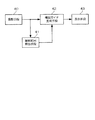
図6は、付記1の構成図である。なお、図6と図1との対応について説明する。図6に示す撮影手段40は、図1の光学部2に相当し、撮影範囲算出手段42は、図1の制御部3における演算部11による撮影シーン・主要被写体認識手段と構図フレーム枠検知手段とに相当する。また、図6の構図ガイド生成手段42は、図1の制御部3における演算部11による構図ガイド生成手段に相当する。そして、図6の表示手段43は、図1の表示部4に相当する。
The features of the present invention will be described below.
A part or all of the above-described embodiment can be described as in the following supplementary notes, but is not limited thereto.
(Appendix 1)
FIG. 6 is a configuration diagram of Supplementary Note 1. The correspondence between FIG. 6 and FIG. 1 will be described. The
この図に示すように、付記1記載の発明は、
画像を取り込む撮影手段40と、
前記画像を表示する表示手段41と、
前記撮影手段40によって取り込まれた前記画像に基づいて、所定の構図条件を満足する構図となる撮影範囲を求める撮影範囲算出手段41と、
前記所定の構図条件を満足する構図となる撮影範囲を、前記撮影手段40により取り込まれた画像上に重ねて合成した構図ガイド画像を生成する構図ガイド生成手段42と、
前記構図ガイド画像を表示する表示手段43と
を備えることを特徴とする撮像装置である。
As shown in this figure, the invention described in Appendix 1 is
Photographing means 40 for capturing an image;
Display means 41 for displaying the image;
An imaging
A composition guide generating means for generating a composition guide image by superimposing the photographing range that satisfies the predetermined composition condition on the image captured by the photographing
An image pickup apparatus comprising: display means 43 for displaying the composition guide image.
(付記2)
前記撮影範囲算出手段は、前記撮影手段により取り込まれた画像の中から、主要被写体と他の被写体とを認識する撮影シーン・主要被写体認識手段と、前記撮影シーン・主要被写体認識手段により認識された前記主要被写体と前記他の被写体とが前記所定の構図条件を満足する構図となる撮影範囲を示す構図フレーム枠の位置座標を算出する構図フレーム枠検知手段とを備え、前記構図ガイド生成手段は、前記算出された位置座標に基づいて、前記構図フレーム枠を前記撮影手段により取り込まれた画像上に重ねて合成した構図ガイド画像を生成することを特徴とする付記1に記載の撮像装置である。
(Appendix 2)
The photographing range calculating means is recognized by a photographing scene / main subject recognizing means for recognizing a main subject and another subject from the image captured by the photographing means, and the photographing scene / main subject recognizing means. A composition frame frame detecting means for calculating a position coordinate of a composition frame frame indicating a photographing range in which the main subject and the other subject satisfy the predetermined composition condition; and the composition guide generating means comprises: The imaging apparatus according to appendix 1, wherein a composition guide image is generated by superimposing the composition frame frame on an image captured by the photographing unit based on the calculated position coordinates.
(付記3)
前記構図フレーム枠検知手段は、前記構図フレーム枠が前記撮影手段により取り込まれた画像内に収まる場合には、前記構図フレーム枠の位置座標を算出する一方、前記構図フレーム枠が前記撮影手段により取り込まれた画像内に収まらない場合には、前記構図フレーム枠が前記撮影手段により取り込まれた画像内に収めさせるべく前記撮影手段による撮影領域の移動方向を算出し、前記構図ガイド生成手段は、前記構図フレーム枠が前記撮影手段により取り込まれた画像内に収まる場合には、前記構図フレーム枠検知手段により算出された位置座標に基づいて、前記構図フレーム枠を前記撮影手段により取り込まれた画像上に重ねて合成した構図ガイド画像を生成し、前記構図フレーム枠が前記撮影手段により取り込まれた画像内に収まらない場合には、前記構図フレーム枠に加えて、前記構図フレーム枠検知手段により算出された移動方向を示す視野移動方向マークを、前記撮影手段により取り込まれた画像上に重ねて合成した構図ガイド画像を生成することを特徴とする付記2に記載の撮像装置である。
(Appendix 3)
The composition frame detection unit calculates the position coordinates of the composition frame when the composition frame falls within the image captured by the photographing unit, while the composition frame frame is captured by the photographing unit. If the image does not fit in the image, the composition frame frame calculates the moving direction of the photographing area by the photographing means so as to be contained in the image captured by the photographing means, and the composition guide generating means When the composition frame frame fits in the image captured by the photographing unit, the composition frame frame is placed on the image captured by the photographing unit based on the position coordinates calculated by the composition frame frame detection unit. A composition guide image that is superimposed and synthesized is generated, and the composition frame frame is not included in the image captured by the photographing means. The composition guide image in which the visual field movement direction mark indicating the movement direction calculated by the composition frame frame detection unit is superimposed on the image captured by the photographing unit in addition to the composition frame frame. The imaging device according to
(付記4)
撮影操作が入力される入力手段と、前記入力手段から撮影操作が入力されると、前記撮影手段により取り込まれた画像を、前記構図フレーム枠検知手段で得られた構図フレーム枠に従ってトリミングして記録画像を生成する構図トリミング手段とを更に備えることを特徴とする付記1から3のいずれかに記載の撮像装置である。
(Appendix 4)
An input unit for inputting a shooting operation, and when a shooting operation is input from the input unit, the image captured by the shooting unit is trimmed and recorded in accordance with the composition frame frame obtained by the composition frame frame detection unit. The imaging apparatus according to any one of appendices 1 to 3, further comprising composition trimming means for generating an image.
(付記5)
撮像素子によって画像を取り込む撮影ステップと、前記撮影ステップで取り込まれた前記画像に基づいて、所定の構図条件を満足する構図となる撮影範囲を求める撮影範囲算出ステップと、前記所定の構図条件を満足する構図となる撮影範囲を、前記撮影ステップで取り込まれた前記画像上に重ねて合成した構図ガイド画像を生成する構図ガイド生成ステップと、前記構図ガイド画像を表示する表示ステップとを含むことを特徴とする撮像方法である。
(Appendix 5)
A shooting step for capturing an image with an image sensor, a shooting range calculating step for obtaining a shooting range that satisfies a predetermined composition condition based on the image captured in the shooting step, and the predetermined composition condition A composition guide generating step for generating a composition guide image obtained by superimposing and synthesizing a photographing range to be a composition to be composed on the image captured in the photographing step; and a display step for displaying the composition guide image. This is an imaging method.
(付記6)
撮像装置のコンピュータに、撮像素子によって画像を取り込む撮影機能、前記撮影機能で取り込まれた前記画像に基づいて、所定の構図条件を満足する構図となる撮影範囲を求める撮影範囲算出機能、前記所定の構図条件を満足する構図となる撮影範囲を、前記撮影ステップで取り込まれた前記画像上に重ねて合成した構図ガイド画像を生成する構図ガイド生成機能、前記構図ガイド画像を表示する表示機能を実行させることを特徴とするプログラムである。
(Appendix 6)
An imaging function for capturing an image with an imaging element in a computer of an imaging device, an imaging range calculation function for obtaining an imaging range that satisfies a predetermined composition condition based on the image captured by the imaging function, and the predetermined A composition guide generation function for generating a composition guide image in which a photographing range that satisfies a composition condition is superimposed on the image captured in the photographing step and synthesized, and a display function for displaying the composition guide image are executed. It is a program characterized by this.
1 撮像装置
2 光学部
3 制御部
4 表示部
5 入力部
6 記憶部
7 レンズ
8 撮像素子
11 演算部
12 主記憶部
13 表示制御部
14 入力制御部
15 記憶制御部
16 データ処理部
20 ライブ画像
21 撮影用画像
22 構図ガイド画像
23 撮影画像ファイル
30 主要被写体マーク
31 境界マーク
33a 構図フレーム枠
33b 視野移動方向マーク
DESCRIPTION OF SYMBOLS 1
Claims (6)
前記撮影手段によって取り込まれた画像に基づいて、所定の構図条件を満足する構図となる撮影範囲を求める撮影範囲算出手段と、
前記所定の構図条件を満足する構図となる撮影範囲を、前記撮影手段により取り込まれた画像上に重ねて合成した構図ガイド画像を生成する構図ガイド生成手段と、
前記構図ガイド画像を表示する表示手段と
を備えることを特徴とする撮像装置。 Photographing means for capturing images;
An imaging range calculation means for obtaining an imaging range that achieves a composition that satisfies a predetermined composition condition based on the image captured by the imaging means;
A composition guide generating means for generating a composition guide image in which a photographing range that satisfies the predetermined composition condition is superimposed on an image captured by the photographing means;
An image pickup apparatus comprising: display means for displaying the composition guide image.
前記撮影手段により取り込まれた画像の中から、主要被写体と他の被写体とを認識する撮影シーン・主要被写体認識手段と、
前記撮影シーン・主要被写体認識手段により認識された前記主要被写体と前記他の被写体とが前記所定の構図条件を満足する構図となる撮影範囲を示す構図フレーム枠の位置座標を算出する構図フレーム枠検知手段と
を備え、
前記構図ガイド生成手段は、
前記算出された位置座標に基づいて、前記構図フレーム枠を前記撮影手段により取り込まれた画像上に重ねて合成した構図ガイド画像を生成する
ことを特徴とする請求項1に記載の撮像装置。 The photographing range calculation means includes
A photographic scene / main subject recognizing means for recognizing a main subject and other subjects from the image captured by the photographing means;
Composition frame frame detection for calculating position coordinates of a composition frame frame indicating a photographing range in which the main subject recognized by the photographing scene / main subject recognition means and the other subject satisfy the predetermined composition condition. Means and
The composition guide generation means includes:
The imaging apparatus according to claim 1, wherein a composition guide image is generated by superimposing the composition frame frame on an image captured by the photographing unit based on the calculated position coordinates.
前記構図フレーム枠が前記撮影手段により取り込まれた画像内に収まる場合には、前記構図フレーム枠の位置座標を算出する一方、前記構図フレーム枠が前記撮影手段により取り込まれた画像内に収まらない場合には、前記構図フレーム枠が前記撮影手段により取り込まれた画像内に収めさせるべく前記撮影手段による撮影領域の移動方向を算出し、
前記構図ガイド生成手段は、
前記構図フレーム枠が前記撮影手段により取り込まれた画像内に収まる場合には、前記構図フレーム枠検知手段により算出された位置座標に基づいて、前記構図フレーム枠を前記撮影手段により取り込まれた画像上に重ねて合成した構図ガイド画像を生成し、前記構図フレーム枠が前記撮影手段により取り込まれた画像内に収まらない場合には、前記構図フレーム枠に加えて、前記構図フレーム枠検知手段により算出された移動方向を示す視野移動方向マークを、前記撮影手段により取り込まれた画像上に重ねて合成した構図ガイド画像を生成する
ことを特徴とする請求項2に記載の撮像装置。 The composition frame frame detecting means includes:
When the composition frame frame fits in the image captured by the photographing unit, the position coordinates of the composition frame frame are calculated, while the composition frame frame does not fit in the image captured by the photographing unit Calculating the moving direction of the shooting area by the shooting means so that the composition frame frame is contained in the image captured by the shooting means;
The composition guide generation means includes:
When the composition frame frame fits in the image captured by the photographing unit, the composition frame frame is displayed on the image captured by the photographing unit based on the position coordinates calculated by the composition frame frame detection unit. If the composition frame frame does not fit within the image captured by the photographing unit, the composition guide frame image is calculated by the composition frame frame detection unit in addition to the composition frame frame. The imaging apparatus according to claim 2, wherein a composition guide image is generated by superimposing a visual field movement direction mark indicating the movement direction on an image captured by the photographing unit.
前記入力手段から撮影操作が入力されると、前記撮影手段により取り込まれた画像を、前記構図フレーム枠検知手段で得られた構図フレーム枠に従ってトリミングして記録画像を生成する構図トリミング手段と
を更に備えることを特徴とする請求項1から3のいずれかに記載の撮像装置。 An input means for inputting a shooting operation;
Composition trimming means for trimming an image captured by the photographing means in accordance with a composition frame frame obtained by the composition frame frame detection means to generate a recorded image when a photographing operation is input from the input means; The imaging apparatus according to claim 1, further comprising: an imaging apparatus according to claim 1.
前記撮影ステップで取り込まれた前記画像に基づいて、所定の構図条件を満足する構図となる撮影範囲を求める撮影範囲算出ステップと、
前記所定の構図条件を満足する構図となる撮影範囲を、前記撮影ステップで取り込まれた前記画像上に重ねて合成した構図ガイド画像を生成する構図ガイド生成ステップと、
前記構図ガイド画像を表示する表示ステップと
を含むことを特徴とする撮像方法。 A shooting step for capturing an image with an image sensor;
A shooting range calculation step for obtaining a shooting range that is a composition that satisfies a predetermined composition condition based on the image captured in the shooting step;
A composition guide generating step for generating a composition guide image in which a photographing range that satisfies the predetermined composition condition is superimposed on the image captured in the photographing step and combined;
And a display step for displaying the composition guide image.
撮像素子によって画像を取り込む撮影機能、
前記撮影機能で取り込まれた前記画像に基づいて、所定の構図条件を満足する構図となる撮影範囲を求める撮影範囲算出機能、
前記所定の構図条件を満足する構図となる撮影範囲を、前記撮影ステップで取り込まれた前記画像上に重ねて合成した構図ガイド画像を生成する構図ガイド生成機能、
前記構図ガイド画像を表示する表示機能
を実行させることを特徴とするプログラム。
In the computer of the imaging device,
Shooting function to capture images with the image sensor,
A shooting range calculation function for obtaining a shooting range that is a composition satisfying a predetermined composition condition based on the image captured by the shooting function;
A composition guide generation function for generating a composition guide image by combining a photographing range that satisfies the predetermined composition condition on the image captured in the photographing step;
A program for executing a display function for displaying the composition guide image.
Priority Applications (1)
| Application Number | Priority Date | Filing Date | Title |
|---|---|---|---|
| JP2012046039A JP2013183306A (en) | 2012-03-02 | 2012-03-02 | Imaging apparatus, imaging method, and program |
Applications Claiming Priority (1)
| Application Number | Priority Date | Filing Date | Title |
|---|---|---|---|
| JP2012046039A JP2013183306A (en) | 2012-03-02 | 2012-03-02 | Imaging apparatus, imaging method, and program |
Publications (1)
| Publication Number | Publication Date |
|---|---|
| JP2013183306A true JP2013183306A (en) | 2013-09-12 |
Family
ID=49273675
Family Applications (1)
| Application Number | Title | Priority Date | Filing Date |
|---|---|---|---|
| JP2012046039A Pending JP2013183306A (en) | 2012-03-02 | 2012-03-02 | Imaging apparatus, imaging method, and program |
Country Status (1)
| Country | Link |
|---|---|
| JP (1) | JP2013183306A (en) |
Cited By (7)
| Publication number | Priority date | Publication date | Assignee | Title |
|---|---|---|---|---|
| WO2015072167A1 (en) * | 2013-11-18 | 2015-05-21 | オリンパス株式会社 | Image capture apparatus, image capture system, image capture method, and image capture program |
| KR20150072112A (en) * | 2013-12-19 | 2015-06-29 | 엘지전자 주식회사 | Method and system for remote-controlling pictur-taking, device and method for managing the same |
| KR20150124527A (en) * | 2014-04-28 | 2015-11-06 | 팅크웨어(주) | Electronic apparatus, control method of electronic apparatus and computer readable recording medium |
| JP2018125729A (en) * | 2017-02-01 | 2018-08-09 | キヤノン株式会社 | Imaging controller, control method and program thereof, and recording medium |
| JP2020154694A (en) * | 2019-03-20 | 2020-09-24 | オリンパス株式会社 | Imaging device, image composition method and image composition program |
| JP2020182075A (en) * | 2019-04-24 | 2020-11-05 | キヤノン株式会社 | Imaging apparatus, control method for the same, program, storage medium |
| JP7458730B2 (en) | 2019-09-30 | 2024-04-01 | キヤノン株式会社 | Information processing device, control method for information processing device, and program thereof |
-
2012
- 2012-03-02 JP JP2012046039A patent/JP2013183306A/en active Pending
Cited By (13)
| Publication number | Priority date | Publication date | Assignee | Title |
|---|---|---|---|---|
| JP2015099994A (en) * | 2013-11-18 | 2015-05-28 | オリンパスイメージング株式会社 | Imaging apparatus, imaging system, imaging method, and imaging program |
| WO2015072167A1 (en) * | 2013-11-18 | 2015-05-21 | オリンパス株式会社 | Image capture apparatus, image capture system, image capture method, and image capture program |
| US9681054B2 (en) | 2013-11-18 | 2017-06-13 | Olympus Corporation | Imaging apparatus, imaging system, imaging method, and computer-readable recording medium |
| KR102138523B1 (en) * | 2013-12-19 | 2020-08-11 | 엘지전자 주식회사 | Method and system for remote-controlling pictur-taking, device and method for managing the same |
| KR20150072112A (en) * | 2013-12-19 | 2015-06-29 | 엘지전자 주식회사 | Method and system for remote-controlling pictur-taking, device and method for managing the same |
| KR20150124527A (en) * | 2014-04-28 | 2015-11-06 | 팅크웨어(주) | Electronic apparatus, control method of electronic apparatus and computer readable recording medium |
| KR102158167B1 (en) * | 2014-04-28 | 2020-09-22 | 팅크웨어(주) | Electronic apparatus, control method of electronic apparatus and computer readable recording medium |
| JP2018125729A (en) * | 2017-02-01 | 2018-08-09 | キヤノン株式会社 | Imaging controller, control method and program thereof, and recording medium |
| JP2020154694A (en) * | 2019-03-20 | 2020-09-24 | オリンパス株式会社 | Imaging device, image composition method and image composition program |
| JP7163228B2 (en) | 2019-03-20 | 2022-10-31 | オリンパス株式会社 | IMAGING DEVICE, IMAGE SYNTHESIS METHOD, AND IMAGE SYNTHESIS PROGRAM |
| JP2020182075A (en) * | 2019-04-24 | 2020-11-05 | キヤノン株式会社 | Imaging apparatus, control method for the same, program, storage medium |
| JP7450343B2 (en) | 2019-04-24 | 2024-03-15 | キヤノン株式会社 | Imaging device, its control method, program, storage medium |
| JP7458730B2 (en) | 2019-09-30 | 2024-04-01 | キヤノン株式会社 | Information processing device, control method for information processing device, and program thereof |
Similar Documents
| Publication | Publication Date | Title |
|---|---|---|
| KR101783059B1 (en) | Image processing device, and control method and computer readable medium | |
| WO2016002228A1 (en) | Image-capturing device | |
| JP2013183306A (en) | Imaging apparatus, imaging method, and program | |
| JP2015012480A (en) | Image processing apparatus and image processing method | |
| JP2011199566A (en) | Imaging apparatus, imaging method and program | |
| JP2013070164A (en) | Imaging device and imaging method | |
| JP2008003335A (en) | Imaging apparatus, focus control method, focus control program | |
| JP2012222495A (en) | Image processor, image processing method, and program | |
| KR20120002834A (en) | Image pickup apparatus for providing reference image and method for providing reference image thereof | |
| JP2011217103A (en) | Compound eye photographing method and apparatus | |
| JP2009171428A (en) | Control method and program for digital camera apparatus and electronic zoom | |
| TWI693828B (en) | Image-capturing device and method for operating the same | |
| JP2021021857A (en) | Imaging apparatus and control method thereof | |
| JP2011040896A (en) | Image capturing apparatus and method of controlling the same | |
| WO2018196854A1 (en) | Photographing method, photographing apparatus and mobile terminal | |
| JP2009081530A (en) | Imaging apparatus and imaging method | |
| JP2009053786A (en) | Image processor, imaging apparatus, image processing method, and program | |
| JP2007133810A (en) | Image processor | |
| JP4807623B2 (en) | Imaging apparatus, imaging method, and imaging program | |
| JP5278483B2 (en) | Imaging apparatus, imaging method, and imaging program | |
| JP6768449B2 (en) | Imaging control device, control method and program of imaging device | |
| JP6460310B2 (en) | Imaging apparatus, image display method, and program | |
| JP5892211B2 (en) | Imaging apparatus and program | |
| JP5962974B2 (en) | Imaging apparatus, imaging method, and program | |
| JP6604998B2 (en) | Image processing apparatus, imaging apparatus, image processing apparatus control method, and program |