JP2008003335A - Imaging apparatus, focus control method, focus control program - Google Patents
Imaging apparatus, focus control method, focus control program Download PDFInfo
- Publication number
- JP2008003335A JP2008003335A JP2006173235A JP2006173235A JP2008003335A JP 2008003335 A JP2008003335 A JP 2008003335A JP 2006173235 A JP2006173235 A JP 2006173235A JP 2006173235 A JP2006173235 A JP 2006173235A JP 2008003335 A JP2008003335 A JP 2008003335A
- Authority
- JP
- Japan
- Prior art keywords
- focus
- image
- frame
- focus frame
- unit
- Prior art date
- Legal status (The legal status is an assumption and is not a legal conclusion. Google has not performed a legal analysis and makes no representation as to the accuracy of the status listed.)
- Pending
Links
Images


Abstract
Description
本発明は、モニタ画面に表示されたフォーカス枠に基づいてフォーカス制御を行うデジタルカメラ等の撮像装置、フォーカス制御方法及びフォーカス制御プログラムに関する。 The present invention relates to an imaging apparatus such as a digital camera that performs focus control based on a focus frame displayed on a monitor screen, a focus control method, and a focus control program.
デジタルカメラなどの撮像装置では、被写体に自動的にピントを合わせるAF機能(自動合焦機能)を備えるものがある。このAF機能では、例えばシャッターキーを半押し操作することで動作し、オートフォーカスの対象位置(例えば画面の中央)にピントが合うようにフォーカスレンズを移動させてその位置にピントを合わせる。その際、オートフォーカスの対象位置をユーザに知らしめるためにオートフォーカス枠(以下、AF枠)を表示することが一般的に行われている。 Some imaging devices such as digital cameras have an AF function (automatic focusing function) for automatically focusing on a subject. This AF function operates, for example, by pressing the shutter key halfway, and moves the focus lens so that it is focused on the target position of autofocus (for example, the center of the screen), and focuses on that position. At that time, it is common practice to display an autofocus frame (hereinafter referred to as an AF frame) in order to inform the user of the target position of autofocus.
上記従来の技術では合焦位置は画面中央に固定されているが、ピントを合わせたい被写体が常に画面中央にあるわけではないのでピントを合わせたい被写体が画面中央になるようにカメラを動かさなければならないといった問題点があった。このような問題点を解決するものとして、例えば特許文献1には、テレビカメラ等のモニタ画面上の操作をタッチパネルにより検出し、その操作によりフォーカス枠の位置及び大きさを変更することにより、主要被写体の画面上の位置や大きさに応じてフォーカス枠の位置及び大きさを設定、変更できるようにしたオートフォーカスシステムが開示されている。
しかしながら、上記特許文献1に開示の技術においても、未だフォーカス枠の位置や大きさ等といった状態を変化させるための自由度は制限されるものであり、しばしば不都合が生じることがあった。例えば、フォーカス枠をカメラまたは被写体の傾きに合わせて順方向または逆方向に回転させたほうが見易い場合があるが、上記特許文献1に開示の技術ではフォーカス枠を回転することはできなかった。
However, even in the technique disclosed in
本発明は、上記課題を解決するためになされたものであり、簡単なキー操作若しくは認識処理による被写体の認識結果に基づいて、オートフォーカス枠の表示状態の制御が可能な撮像装置、フォーカス制御方法及びフォーカス制御プログラムの提供を目的とする。 The present invention has been made to solve the above problems, and an imaging apparatus and a focus control method capable of controlling the display state of an autofocus frame based on a recognition result of a subject by simple key operation or recognition processing And a focus control program.
上記課題を解決するために、請求項1に記載の発明の撮像装置では、被写体光像から撮像素子を介して画像を得る画像取得部と、前記画像取得部により得られた画像を表示する画像表示部と、合焦用のフォーカス枠を前記画像表示部に表示されている画像上に重畳表示するフォーカス枠表示制御手段と、前記フォーカス枠内の画像が合焦するようにフォーカスレンズを駆動制御する合焦制御手段と、を備えた撮像装置であって、所定の指示を入力する入力手段と、所定のタイミングを指示するタイミング指示手段と、前記フォーカス枠の状態を変化可能に生成するフォーカス枠生成手段と、を備え、前記フォーカス枠生成手段は、前記入力手段を介した指示に基づいてフォーカス枠の状態を変化させ、前記フォーカス枠表示制御手段は、前記フォーカス枠生成手段により生成されたフォーカス枠を前記画像表示部に表示し、前記合焦制御手段は、前記タイミング指示手段により指示された所定のタイミングのときに前記画像表示部に表示されているフォーカス枠内の画像が合焦するようにフォーカスレンズを駆動制御することを特徴とする。 In order to solve the above problems, in the imaging apparatus according to the first aspect of the present invention, an image acquisition unit that obtains an image from a subject light image via an imaging element, and an image that displays the image obtained by the image acquisition unit A display unit, a focus frame display control unit that superimposes and displays a focus frame for focusing on an image displayed on the image display unit, and drive control of the focus lens so that an image in the focus frame is in focus An in-focus control unit that includes an input unit that inputs a predetermined instruction, a timing instruction unit that instructs a predetermined timing, and a focus frame that variably generates a state of the focus frame Generating means, wherein the focus frame generating means changes the state of the focus frame based on an instruction via the input means, and the focus frame display control means The focus frame generated by the focus frame generation unit is displayed on the image display unit, and the focus control unit displays the focus displayed on the image display unit at a predetermined timing instructed by the timing instruction unit. The focus lens is driven and controlled so that the image in the frame is in focus.
また、請求項2に記載の発明は上記請求項1に記載の発明の撮像装置において、前記フォーカス枠生成手段は、前記入力手段を介した指示に基づいてフォーカス枠を回転させることを特徴とする。 According to a second aspect of the present invention, in the imaging apparatus according to the first aspect of the invention, the focus frame generation unit rotates the focus frame based on an instruction via the input unit. .
また、請求項3に記載の発明は上記請求項1に記載の発明の撮像装置において、前記フォーカス枠生成手段は、フォーカス枠のパターンを予め登録した枠パターン登録メモリを備え、現在選択しているフォーカス枠を、前記入力手段を介した指示に基づいて前記枠パターン登録メモリから読み出した新たなフォーカス枠のパターンに置換することを特徴とする。 According to a third aspect of the present invention, in the imaging apparatus according to the first aspect of the invention, the focus frame generation means includes a frame pattern registration memory in which a focus frame pattern is registered in advance, and is currently selected. The focus frame is replaced with a new focus frame pattern read from the frame pattern registration memory based on an instruction via the input unit.
また、請求項4に記載の発明は上記請求項1に記載の発明の撮像装置において、フォーカス枠生成手段は、前記入力手段を介した指示に基づいてフォーカス枠のサイズを伸縮させることを特徴とする。 According to a fourth aspect of the present invention, in the imaging apparatus according to the first aspect of the invention, the focus frame generating means expands and contracts the size of the focus frame based on an instruction via the input means. To do.
また、請求項5に記載の発明は上記請求項1に記載の発明の撮像装置において、前記フォーカス枠表示制御手段は、前記入力手段を介した指示に基づいて前記画像表示部の所定の位置にフォーカス枠を移動表示させることを特徴とする。 According to a fifth aspect of the present invention, in the imaging apparatus according to the first aspect of the invention, the focus frame display control unit is positioned at a predetermined position of the image display unit based on an instruction via the input unit. The focus frame is moved and displayed.
また、請求項6に記載の発明の撮像装置では、被写体光像から撮像素子を介して画像を得る画像取得部と、前記画像取得部により得られた画像を表示する画像表示部と、合焦用のフォーカス枠を前記画像表示部に表示されている画像上に重畳表示するフォーカス枠表示制御手段と、前記フォーカス枠内の画像が合焦するようにフォーカスレンズを駆動制御する合焦制御手段と、を備えた撮像装置であって、前記画像中の所定の被写体形状を識別認識する画像認識処理手段と、所定のタイミングを指示するタイミング指示手段と、 前記フォーカス枠の状態を変化可能に生成するフォーカス枠生成手段と、を備え、前記フォーカス枠生成手段は、画像認識処理手段により識別認識された被写体形状に基づいてフォーカス枠の状態を確定させ、前記フォーカス枠表示制御手段は、前記フォーカス枠生成手段により生成されたフォーカス枠を前記画像表示部に表示し、前記合焦制御手段は、前記タイミング指示手段により指示された所定のタイミングのときに前記画像表示部に表示されているフォーカス枠内の画像が合焦するようにフォーカスレンズを駆動制御する
ことを特徴とする。
In the imaging device according to the sixth aspect of the present invention, an image acquisition unit that obtains an image from a subject light image via an imaging device, an image display unit that displays an image obtained by the image acquisition unit, and an in-focus state A focus frame display control unit that superimposes and displays a focus frame on the image displayed on the image display unit; and a focus control unit that drives and controls a focus lens so that an image in the focus frame is focused. , An image recognition processing unit for recognizing and recognizing a predetermined subject shape in the image, a timing instruction unit for instructing a predetermined timing, and generating a state of the focus frame so as to be changeable A focus frame generation means, wherein the focus frame generation means determines the state of the focus frame based on the subject shape identified and recognized by the image recognition processing means, The focus frame display control unit displays the focus frame generated by the focus frame generation unit on the image display unit, and the focus control unit displays the image at a predetermined timing instructed by the timing instruction unit. The focus lens is driven and controlled so that an image in the focus frame displayed on the display unit is in focus.
また、請求項7に記載の発明は上記請求項6に記載の発明の撮像装置において、前記画像中の所定の被写体を選択指示する指示手段を備え、前記画像認識処理手段は、前記指示手段により選択指示された被写体の形状を識別認識することを特徴とする。
The invention according to
また、請求項8に記載の発明は上記請求項6または7に記載の発明の撮像装置において、前記フォーカス枠表示制御手段は、前記画像認識処理手段により識別認識された被写体上に、前記フォーカス枠生成手段により生成されたフォーカス枠を重畳表示することを特徴とする。 According to an eighth aspect of the present invention, in the imaging apparatus according to the sixth or seventh aspect of the invention, the focus frame display control means has the focus frame on the subject identified and recognized by the image recognition processing means. The focus frame generated by the generation unit is displayed in a superimposed manner.
また、請求項9に記載の発明は上記請求項8に記載の発明の撮像装置においてフォーカス枠表示制御手段は、被写体形状とフォーカス枠とが一致するように重畳表示することを特徴とする。
The invention described in
また、請求項10に記載の発明は請求項6から9の何れかに記載の撮像装置において、前記画像表示部は、前記画像取得部により画像が得られる毎に、前記画像取得部により得られた画像を順次更新表示し、 前記画像認識処理手段は、前記更新表示される画像中の所定の被写体形状を識別認識し、前記フォーカス枠生成手段は、前記画像認識処理手段により被写体形状が識別認識される毎に、新たに識別認識された被写体形状に対応するように、前記被写体形状に基づいて新たなフォーカス枠を生成し、前記フォーカス枠表示制御手段は、前記フォーカス枠生成手段により新たなフォーカス枠が生成される毎に、前記フォーカス枠を更新表示することを特徴とする。
Further, in the imaging device according to any one of
また、請求項11に記載の発明のフォーカス制御方法は、被写体光像から撮像素子を介して得られた画像を表示する画像表示工程と、合焦用のフォーカス枠を前記画像上に重畳表示するフォーカス枠表示工程と、前記フォーカス枠内の画像が合焦するようにフォーカスレンズを駆動制御する合焦制御工程とからなるフォーカス制御方法であって、所定の指示を入力する入力工程と、所定のタイミングを指示するタイミング指示工程と、前記フォーカス枠の状態を変化可能に生成するフォーカス枠生成工程と、を有し、前記フォーカス枠生成工程は、前記入力工程による所定の指示に基づいてフォーカス枠の状態を変化させ、 前記フォーカス枠表示制御工程は、前記フォーカス枠生成工程により生成されたフォーカス枠を前記画像上に重畳表示し、前記合焦制御工程は、前記タイミング指示工程により指示された所定のタイミングのときに表示されているフォーカス枠内の画像が合焦するようにフォーカスレンズを駆動制御することを特徴とする。 The focus control method according to an eleventh aspect of the present invention includes an image display step of displaying an image obtained from a subject light image via an image pickup device, and a focus focus frame superimposed on the image. A focus control method comprising a focus frame display step, and a focus control step for driving and controlling the focus lens so that an image in the focus frame is in focus, an input step for inputting a predetermined instruction, A timing instructing step for instructing timing; and a focus frame generating step for generating the state of the focus frame in a changeable manner, wherein the focus frame generating step is based on a predetermined instruction by the input step. The focus frame display control step is configured to superimpose the focus frame generated by the focus frame generation step on the image. And the focus control process is characterized in that the image of the focus frame being displayed when the predetermined timing instructed by the timing instruction step controls driving of the focus lens to focus.
また、請求項12に記載の発明のフォーカス制御方法は、被写体光像から撮像素子を介して得られた画像を表示する画像表示工程と、合焦用のフォーカス枠を前記画像上に重畳表示するフォーカス枠表示工程と、前記フォーカス枠内の画像が合焦するようにフォーカスレンズを駆動制御する合焦制御工程とからなるフォーカス制御方法であって、前記画像中の所定の被写体形状を識別認識する画像認識処理工程と、所定のタイミングを指示するタイミング指示工程と、前記フォーカス枠の状態を変化可能に生成するフォーカス枠生成工程と、を有し、前記フォーカス枠生成工程は、画像認識処理手段により識別認識された被写体形状に基づいてフォーカス枠の状態を確定させ、前記フォーカス枠表示制御工程は、前記フォーカス枠生成工程により生成されたフォーカス枠を前記画像上に重畳表示し、 前記合焦制御工程は、前記タイミング指示工程により指示された所定のタイミングのときに表示されているフォーカス枠内の画像が合焦するようにフォーカスレンズを駆動制御することを特徴とする。 In the focus control method according to the twelfth aspect of the present invention, an image display step for displaying an image obtained from a subject light image via an imaging device and a focus frame for focusing are superimposed and displayed on the image. A focus control method comprising a focus frame display step and a focus control step for driving and controlling a focus lens so that an image in the focus frame is in focus, and identifies and recognizes a predetermined subject shape in the image An image recognition processing step; a timing instruction step for instructing a predetermined timing; and a focus frame generation step for generating the focus frame state in a changeable manner. The focus frame generation step is performed by image recognition processing means. The focus frame state is determined based on the identified and recognized subject shape, and the focus frame display control step includes the focus frame generation step. The generated focus frame is superimposed on the image, and the focus control step is performed so that the image within the focus frame displayed at the predetermined timing instructed by the timing instruction step is in focus. The focus lens is driven and controlled.
また、請求項13に記載の発明のフォーカス制御プログラムは、コンピュータに、被写体光像から撮像素子を介して得られた画像を表示させる画像表示制御手段と、合焦用のフォーカス枠を前記画像上に重畳表示させるフォーカス枠表示制御手段と、前記フォーカス枠内の画像が合焦するようにフォーカスレンズを駆動制御させる合焦制御手段として機能させるフォーカス制御プログラムであって、所定の指示を入力させる入力手段と、所定のタイミングを指示させるタイミング指示手段と、前記フォーカス枠の状態を変化可能に生成させるフォーカス枠生成手段として機能させ、前記フォーカス枠生成手段は、前記入力手段により入力された指示に基づいてフォーカス枠の状態を変化させ、前記フォーカス枠表示制御手段は、前記フォーカス枠生成手段により生成されたフォーカス枠を前記画像上に重畳表示させ、前記合焦制御手段は、前記タイミング指示手段により指示された所定のタイミングのときに前記画像表示部に表示されているフォーカス枠内の画像が合焦するようにフォーカスレンズを駆動制御させることを特徴とする。 According to a thirteenth aspect of the present invention, there is provided a focus control program including: an image display control unit that causes a computer to display an image obtained from a subject light image via an image sensor; and a focus frame for focusing on the image. A focus frame display control unit that superimposes and displays a focus frame, and a focus control program that functions as a focus control unit that drives and controls the focus lens so that an image in the focus frame is focused. Means, a timing instruction means for instructing a predetermined timing, and a focus frame generation means for generating the state of the focus frame in a changeable manner. The focus frame generation means is based on an instruction input by the input means. The focus frame display control means is configured to change the focus frame state. The focus frame generated by the frame generation unit is superimposed on the image, and the focus control unit displays the focus frame displayed on the image display unit at a predetermined timing instructed by the timing instruction unit. The focus lens is driven and controlled so that the inside image is in focus.
また、請求項14に記載の発明のフォーカス制御プログラムは、コンピュータに、被写体光像から撮像素子を介して得られた画像を表示させる画像表示制御手段と、合焦用のフォーカス枠を前記画像上に重畳表示させるフォーカス枠表示制御手段と、前記フォーカス枠内の画像が合焦するようにフォーカスレンズを駆動制御させる合焦制御手段として機能させるフォーカス制御プログラムであって、前記画像中の所定の被写体形状を識別認識する画像認識処理手段と、所定のタイミングを指示するタイミング指示手段と、前記フォーカス枠の状態を変化可能に生成するフォーカス枠生成手段として機能させ、前記フォーカス枠生成手段は、画像認識処理手段により識別認識された被写体形状に基づいてフォーカス枠の状態を確定させ、前記フォーカス枠表示制御手段は、前記フォーカス枠生成手段により生成されたフォーカス枠を前記画像表示部に表示させ、前記合焦制御手段は、前記タイミング指示手段により指示された所定のタイミングのときに前記画像表示部に表示されているフォーカス枠内の画像が合焦するようにフォーカスレンズを駆動制御させることを特徴とする。 According to a fourteenth aspect of the present invention, there is provided a focus control program comprising: an image display control unit that causes a computer to display an image obtained from a subject light image via an image sensor; and a focus frame for focusing on the image. A focus frame display control unit that superimposes and displays a focus frame, and a focus control program that functions as a focus control unit that drives and controls a focus lens so that an image in the focus frame is in focus, and includes a predetermined subject in the image The image recognition processing means for recognizing and recognizing the shape, the timing instruction means for instructing a predetermined timing, and the focus frame generation means for generating the state of the focus frame in a changeable manner, the focus frame generation means Based on the subject shape identified and recognized by the processing means, the state of the focus frame is determined, and the frame is The focus frame display control unit displays the focus frame generated by the focus frame generation unit on the image display unit, and the focusing control unit displays the image at a predetermined timing instructed by the timing instruction unit. The focus lens is driven and controlled so that the image within the focus frame displayed on the display unit is focused.
本発明によれば、簡単なキー操作もしくは認識処理による被写体の認識結果に基づいて、フォーカス枠の表示状態、例えば、フォーカス枠の回転、フォーカス枠の置換、伸縮、移動等の制御を行ってフォーカス枠内の画像にピントを合わせることができるので、ピントが被写体でなく背景に合う現象(いわゆる「中抜け」)、が生じない。請求項1〜請求項5、請求項11、および請求項13に記載の発明によれば、ユーザによる簡単なキー操作に基づく指示によりフォーカス枠の状態の制御を行うことができる。また、請求項6〜請求項9、請求項12、および請求項14に記載の発明によれば、画像認識処理による被写体形状の認識結果に基づいてフォーカス枠の状態の制御を行うことができる。また、請求項10に記載の発明によれば、被写体形状や位置の変化に追従させてフォーカス枠を自動的に変化させることができるので、被写体形状や位置が変化してもピントがずれない。
According to the present invention, the focus frame display state, for example, focus frame rotation, focus frame replacement, expansion / contraction, movement, and the like is controlled based on the recognition result of the subject by simple key operation or recognition processing. Since the image within the frame can be focused, the phenomenon that the focus is not on the subject but on the background (so-called “missing”) does not occur. According to the invention described in
(実施形態1)
本実施形態では、簡単なキー操作で、または自動的に、オートフォーカス枠(以下、AF枠)を回転させる例について述べる。
(Embodiment 1)
In the present embodiment, an example in which an autofocus frame (hereinafter referred to as an AF frame) is rotated by a simple key operation or automatically will be described.
図1は、本発明に係る撮像装置の一実施例としてのデジタルカメラの外観を示す図であり、ここでは主として正面(図1(a))、背面(図1(b))、および上面(図1(c))の外観を示す。デジタルカメラ100は、図1(a)に示すように正面側に撮像レンズ1を有している。また、デジタルカメラ100の背面には、図1(b)に示すように、モードダイアル3、液晶画面4、カーソルキー5、SETボタン6、メニューキー10等が設けられている。また、上面には図1(c)に示すようにズームレバー7、シャッターキー8、および電源ボタン9が設けられている。なお、側部には図示されていないが、パーソナルコンピュータ(以下、パソコン)やモデム等の外部装置とUSBケーブルに接続する場合に用いるUSB端子接続部が設けられている。
FIG. 1 is a diagram showing the appearance of a digital camera as an embodiment of an imaging apparatus according to the present invention. Here, mainly a front surface (FIG. 1A), a rear surface (FIG. 1B), and an upper surface ( The external appearance of FIG.1 (c) is shown. The
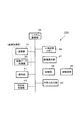
図2は本実施形態に係わるデジタルカメラの電気的構成の一実施例を示すブロック図であり、デジタルカメラ100は、撮像部31、画像データ処理部32、システム制御部35、一時記憶メモリ36、画像表示部37、記録部38、外部入出力部40、操作部41、および枠回転処理部42を備えている。撮像部31および画像データ処理部32は本発明の画像取得部を構成する。また、オートフォーカス機能、および静止画撮影モードや動画撮影モード等の撮影機能とそれらの撮影機能の下で選択可能な本発明に基づくAF枠表示変更モードを有している。
FIG. 2 is a block diagram illustrating an example of the electrical configuration of the digital camera according to the present embodiment. The
撮像部31は、撮影レンズ1のほか、基本モードである撮像モードにおいてズームレンズを移動させて光学ズーム動作を行わせるズーム駆動制御部やフォーカスレンズを移動させて合焦動作を行わせる合焦制御手段としてのAF駆動制御部等を含むレンズ駆動系と、撮像素子、信号変換部、撮像タイミング制御部、撮像素子駆動制御部等を含む撮像系を有しており、撮像レンズ1を経由し、撮像レンズの撮像光軸後方に配置された撮像素子に入射した被写体光像は撮像素子によって光電変換され撮像信号(アナログ)として出力される。撮像素子の出力信号は信号変換部で相関二重サンプリングおよびゲイン調整され、A/D変換によりデジタル信号に変換される。A/D変換された撮像信号は所定の周期で画像データ処理部32に送られる。撮像素子は、被写体の二次元画像を撮像するCMOS(Complementary Metal Oxide Semiconductor)などの固体撮像デバイスであり、典型的には毎秒数十フレームの画像を撮像する。なお、撮像素子はCMOSに限定されない。
In addition to the
画像データ処理部32は、信号変換部から出力されたデジタル信号(画像データ)に対して画像補間処理及びγ補正処理を含むカラープロセス処理を行ってデジタル値の輝度信号Y及び色差信号Cb、Crを生成し、DRAM等の一時記憶メモリ36にバス30を介してDMA転送する。
The image
システム制御部35は、デジタルカメラ100全体の制御動作を司るものであり、CPU若しくはMPU(以下、CPU)と、該CPUで実行される動作プログラム等を記憶したフラッシュメモリ等のプログラム格納メモリ、及びワークメモリとして使用されるRAM等により構成されている。また、システム制御部35は画像データ処理部32からの画像データ(輝度及び色差信号)のDRAM等の一時記憶メモリ36へのDMA転送終了後に、この輝度及び色差信号を一時記憶メモリ36から読出し、画像表示部39の表示用バッファメモリに書き込むよう制御する。
The
また、システム制御部35は、合焦位置を決定する合焦位置決定手段として機能するほか、AF枠表示変更モード時にユーザのキー操作に基づく指示に基づいてAF枠表示制御のタイミングを指示するタイミング指示手段、および合焦対象とする被写体(以下、「主要被写体」と記す)上に表示されているAF枠の表示状態を制御するAF枠表示制御手段として機能する。具体的には、AF枠表示変更モード時に所定の枠回転指示操作または傾き検出部43によるカメラの傾き検出があると枠回転処理部42を制御して液晶画面4上に表示されているAF枠を、例えば、カメラによる傾きを相殺させるように液晶画面4に対して回転させる枠回転制御手段として機能する。
The
一時記憶メモリ36はDRAM等で構成され、撮影モード時にはその一部の領域を画像データ処理部32から取得する撮影画像を一時的に記憶するバッファメモリとして用いることができる。
The
画像表示部37はVRAM等の表示用バッファメモリ、表示制御部、及び液晶画面4を有し、システム制御部35の制御下で表示用バッファメモリに書き込まれた上記輝度及び色差信号を表示制御部を介して定期的に読み出し、これらのデータを基にビデオ信号を生成して上記液晶画面4に出力する。
The
記録部38は、画像データの圧縮または伸張を行うデータ圧縮伸張部と、DRAM等のバッファメモリから転送されるデータの記録媒体39への書き込みや記録媒体39からの読み出しを行うコントローラ等から構成されている。記録媒体39は内蔵メモリ(フラッシュメモリ)や光ディスク、あるいは着脱可能なメモリーカード等の書き換え可能な記録媒体からなり記録部38によって書き込まれた画像データや撮像情報等を保存記録する。
The
外部入出力部40は、デジタルカメラ100とUSBケーブル等の接続手段やインターネット等の通信ネットワークによりデジタルカメラ100に接続する外部装置との間で画像データやプログラム等を入出力する際の入出力インターフェィス等からなる。
The external input /
操作部41は、図1に示したモードダイアル3、カーソルキー5、SETボタン6、ズームレバー7、シャッターキー8、電源ボタン9、およびメニューキー10等のキーと、それらのキーが操作されると操作されたキーの操作信号を生成してシステム制御部35に送出するキー処理部等から構成されており、AF枠表示変更モード時に所定の指示を入力するキー入力手段として機能する。
The
モードダイアル3は撮像モードや再生モードの選択を行うものである。ユーザはモードダイアル3を操作して、静止画撮像モード、マクロ撮像モード、連写モード、速写モード、・・、動画撮像モード等の撮像モードや再生モードを選択することができる。AF枠表示変更モードは撮影モード下で表示される処理選択メニューで選択できる。なお、モードダイアル3でAF枠表示変更モードを選択できるように構成してもよい。
The
カーソルキー5はモード設定やメニュー選択等に際して液晶画面4に表示されるメニューやアイコン等をカーソルでポイント(指定)する際に操作するキーであり、カーソルキー5の操作によりカーソルを上下又は左右に移動させることができる。
The
SETボタン6はカーソルキー5によってカーソル表示されている項目を選択設定する際に押されるキーであるが、本実施形態では、AF枠表示変更モードにおいてSETボタン6をAF枠の枠回転指示手段として用い、例えば、SETボタン6を1回押す毎に表示されているAF枠を液晶画面4に対して所定の角度ずつ回転させる。なお、他のキーをAF枠の枠回転指示手段として構成してもよい。また、デジタルカメラ100にAF枠の枠回転指示用の専用キーを設けるようにしてもよい。
The
ズームレバー7は、ズーム操作に用いられ、光学ズームの場合はズームレバー7の操作に対応してズームレンズ(可変焦点距離レンズ)がワイド側またテレ側に移動され、ズームバー7の操作に対応してズーム値が決定されて、ズーム値の変化に追従して画角が実際に変化し、液晶モニタ画面4にはワイド(広角)画像又はテレ(望遠)画像が表示される。また、電子ズームの場合はズームレバー7の操作に対応してズーム値が決定されるが、実際の画角は変化せず、液晶モニタ画面4にはズーム値に応じたサイズの画像がトリミングされて拡大/縮小表示される。また、AF枠表示変更モードが選択されている場合に、SETボタン6に代えて、ズームレバー7をAF枠の枠回転指示手段として用い、ズームレバー7を右に回転させると表示されているAF枠が右に回転し、ズームレバー7を左に回転させると表示されているAF枠が左に回転するようにしてもよい。
The
シャッターキー8は、撮像時にレリーズ操作を行うもので、2段階のストロークを有しており、システム制御部35はシャッターキー8の1段目の操作(半押し状態)でオートフォーカス(AF)と自動露出(AE)を行わせるための合焦指示信号を発生し、2段目の操作(全押し状態)で撮像処理を行うための撮像指示信号を発生する。
The
枠回転処理部42は、AF枠表示変更モード時に、システム制御部35の制御下で枠回転指示に基づいて液晶画面4に表示されているAF枠を左右に所定角度回転させたAF枠データを生成して画像表示部37に送出する。液晶画面4に表示されているAF枠の回転方法は、表示図形に関する公知の回転技術を適宜用いることができる。また、表示されるAF枠は複数でもよい。なお、AF枠表示変更モードが選択されていない場合は枠回転処理部42の動作は禁止され、スルー画像表示時には、例えば、画面中央に矩形のAF枠が表示される。
In the AF frame display change mode, the frame
図3は回転するAF枠の一実施例を示し、図3(a)は、撮影待機時、つまりスルー画像表示時のAF枠30の状態を示す。図示の例では、横長の画面中央に3個の矩形状のAF枠30−1、30−2、30−3が横位置列に表示されている。また、図3(b)は画面に向かって右回りにやや回転させたAF枠30の状態、図3(c)は水平状態から右回りに90°回転させ、画面に垂直になったAF枠30の状態、図3(d)はさらに右回りに回転させたAF枠30の状態を示す。
FIG. 3 shows an example of a rotating AF frame, and FIG. 3A shows the state of the
図4はAF枠回転操作の一実施例を示す図であり、図示の例ではAF枠表示変更モードでユーザによるSETボタン6の操作により枠回転指示が行われる。図4(a)は、撮影待機時、つまりスルー画像表示時に画面中央の被写体40上に表示されるAF枠30を示す。この状態でSETボタン6を押すとAF枠30が右回りに所定角度回転し、図4(b)に示すように、被写体40上に斜めに表示される。何回かSETボタン6を押すと図4(c)に示すようにAF枠30は縦長の被写体40の中央で垂直になり、更にSETボタン6を押すと図4(d)に示すようにAF枠30はさらに右回りに所定角度回転する。
FIG. 4 is a diagram showing an embodiment of the AF frame rotation operation. In the illustrated example, a frame rotation instruction is performed by the user operating the
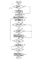
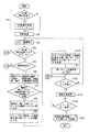
図5は、本実施形態に係わるシステム制御部35によるAF枠表示制御動作例を示すフローチャートであり、デジタルカメラ100に本発明のAF枠回転機能を実現させるためのプログラムを説明するためのものである。以下、図1〜図5に基づいて説明する。
FIG. 5 is a flowchart showing an example of an AF frame display control operation performed by the
デジタルカメラ100の電源キー9がオンのとき、ユーザがモードダイアル3を操作して撮影モードを選択すると、システム制御部35は画像表示部37を制御して液晶画面4にAF枠表示変更モードを含む選択メニューを表示し、ユーザがAF枠表示変更モードを選択するとAF枠表示変更フラグをオンにしてステップS2に進み、そうでない場合はAF枠表示変更フラグはオフのままにしてステップS2に進む(ステップS1)。
When the
次に、システム制御部35は、撮影用の各種初期設定を行った後(ステップS2)、液晶画面4の所定の位置、例えば中央に所定サイズのAF枠を表示する(ステップS3)。これにより、ユーザはスルー表示されている画像のうちピントを合わせたい主要被写体の中心部がAF枠に入るようにフレーミングを行って好適な構図の画像を画面内に収めるようにできる。なお、表示するAF枠は一つとは限られず、例えば、図3に示したように複数個でもよい。この場合、選択メニューで表示するAF枠の個数を指定できるようにしてもよいし、オートフォース枠が表示された後に例えばメニューキー10を押すと枠の個数を指定するメニューが表示され、枠の個数を指定できるようにしてもよい。
Next, after performing various initial settings for photographing (step S2), the
次に、システム制御部35は、撮像部31および画像データ処理部32を制御してその時点のズーム値に対応した焦点距離でAE処理を実行させ、撮影レンズ1を介して取り込んだ被写体光像から画像データを得ると共に自動ホワイトバランス(AWB)処理により光源の色に対応したホワイトバランスになるように調整を施した上で、所定の周期で1フレーム分の画像データを得て一時記憶メモリ36にDMA転送し、一時記憶メモリ36に取り込んだ画像データから画素数を間引いたビデオスルー画像データで画像記憶部37の表示用バッファを書き換えて液晶画面4にスルー画像を表示する(ステップS4)。
Next, the
また、システム制御部35は、AF枠表示変更フラグの値を調べ、AF枠表示変更フラグがオンの場合はステップS6に進み、そうでない場合はステップS8に進む(ステップS5)。
Further, the
ステップS5で、AF枠表示変更フラグがオンの場合は、システム制御部35は、操作部41からの信号を調べ、AF枠回転指示信号を受け取った場合にはステップS7に進み、そうでない場合はステップS8に進む(ステップS6)。
If the AF frame display change flag is on in step S5, the
ステップS6で、AF枠回転指示信号を受け取ると、システム制御部35は、枠回転処理部42に制御信号を送出し、表示されているAF枠を所定の方向、例えば図3に示したように右回り方向に所定角度だけ回転させる(ステップS7)。AF枠回転指示信号は所定のキー、例えば、SETキー6を押すと操作部41からシステム制御部35に送出される。なお、後述する変形例1−1で詳述するように、主要被写体、つまり、合焦対象とする被写体を変更したり、変形例1−2で詳述するように、カメラの傾きを検出して自動的にAF枠を、例えば、地上面に対して水平方向になるように回転させるように構成することもできる。
Upon receiving the AF frame rotation instruction signal in step S6, the
システム制御部35は操作部41からの信号を調べ、シャッターキー8の一段目の操作(半押し状態)がなされた場合はステップS9に進み、シャッターキー8が押されていない場合はステップS4に戻る(ステップS8)。
The
シャッターキー8の一段目の操作(半押し状態)がなされると、システム制御部35は、自動合焦処理(オートフォーカス処理)を行う。即ち、撮像部31を制御して被写体画像エリアのうち、このときに表示されているAF枠によって区画された範囲としてのフォーカスエリアに対して合焦するようにフォーカスレンズを移動させると共に絞り制御を行う。具体的には、フォーカスレンズを所定の移動範囲内で、所定間隔毎に順次移動させる。そして、フォーカスレンズの各移動位置での被写体画像におけるフォーカスエリア内画像に基づいて合焦評価値を算出し、得られた各合焦評価値からフォーカスエリア内の被写体像が合焦しているフォーカスレンズ位置を合焦位置として導出し、この導出された合焦位置にフォーカスレンズを移動させる。そして、自動合焦処理が終わると、フォーカスレンズを合焦位置にロックしてステップS10に進む(ステップS9)。なお、図示していないが合焦動作中もスルー画像は表示される。
When the first stage operation (half-pressed state) of the
システム制御部35は操作部41からの信号を調べてシャッターキー8の2段目の操作(全押し状態)がなされたか否かを判定し、シャッターキー8が全押しされた場合はステップS11に進む(ステップS10)。
The
シャッターキー8が全押しされた場合は、その時点で直ちに撮像部31および画像データ処理部32からなる撮像系を制御して撮像を実行する。つまり、その時点で直ちに画像データ処理部32から一時記憶メモリ36への経路を停止してスルー画像取得時とは異なる本撮影時の撮像素子駆動方式への切り替えを実行し、記録部38を制御して画像データを取り込んで画像圧縮処理を施させ、この圧縮データからなる画像ファイルを記録媒体39に記録させる(ステップS11)。
When the
上記図5のフローチャートに示した動作により、AF枠表示変更モードが選択されると、デジタルカメラ100は固定位置若しくは回転操作されたAF枠によって区画された範囲のフォーカスエリアに合焦した画像を撮影することができる。これにより、被写体またはカメラが傾いているような場合に、AF枠を回転させて被写体またはカメラの傾きに合わせることができるので、中抜けが生じない。また、AF枠表示変更モードが選択されない場合には液晶画面4の中央に表示されるAF枠によって区画された範囲のフォーカスエリアに合焦した画像を撮影できる。
When the AF frame display change mode is selected by the operation shown in the flowchart of FIG. 5, the
<変形例1−1>
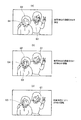
上記図5に示したフローチャートでは、AF枠表示変更モードにおいて、スルー画像表示中に、カメラ中央の被写体を主要被写体としてその上にAF枠を表示し、ユーザがAF枠回転指示を行うとAF枠を回転させるように構成したが、回転だけでなく、図6(a)に示すようにキー操作によりユーザが被写体62の顔部分64を指定すると、図6(b)に示すように指定された被写体62を主要被写体として被写体61上にあったAF枠63を指定された部分64に移動させて表示し、その後にユーザがAF枠の枠回転指示を行うと図6(c)に示すようにAF枠63を回転させて表示するように構成することもできる。
<Modification 1-1>
In the flowchart shown in FIG. 5, in the AF frame display change mode, during the through image display, the subject at the center of the camera is displayed as the main subject, and the AF frame is displayed when the user issues an AF frame rotation instruction. However, in addition to the rotation, when the user designates the
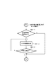
図7はAF枠の表示変更制御動作例(AF枠回転制御動作)の変形例を示すフローチャートであり、図5のフローチャートのステップS6を下記ステップS6−1〜S6−3で置き換えた例である。 FIG. 7 is a flowchart showing a modification of the AF frame display change control operation example (AF frame rotation control operation), in which step S6 in the flowchart of FIG. 5 is replaced by steps S6-1 to S6-3 below. .
図7で、AF枠表示変更フラグがオンの場合は、システム制御部35は、操作部41からの信号を調べ、AF枠の移動指示信号を受け取った場合はステップS6−2に進み、そうでない場合はステップS7に進む(ステップS6−1)。
In FIG. 7, when the AF frame display change flag is on, the
ステップS6−1で、AF枠の移動指示信号を受け取った場合は、システム制御部35は画像表示部37を制御して現在位置に表示されていたAF枠を消去させると共に、受け取った移動指示信号に含まれる移動先の位置に所定サイズのAF枠を表示し、ステップS6−3に進む(ステップS6−2)。移動指示信号は、例えばカーソルキー5を押して上方(↑)、下方(↓)、左方(←)、または右方(→)操作し、押圧を解除した時点(つまり、カーソルキー5から指を離した時点)で操作部41からシステム制御部35に送出され、押圧を解除した位置の画面上の座標を含んでいる。また、移動先でのAF枠表示は移動先の座標(X、Y)がAF枠の中心点と一致するようにしてもよいし、移動先の座標(X、Y)がAF枠の四隅のいずれかと一致するようにしてもよい。なお、AF枠の移動技術は表示図形に関する公知の移動技術を適宜用いることができる。
If an AF frame movement instruction signal is received in step S6-1, the
システム制御部35は、操作部41からの信号を調べ、移動先確定信号を受け取った場合にはステップS7に進んで表示されているAF枠を所定角度回転させる。また、移動先確定信号を受け取っていない場合はステップS6−2に戻る(ステップS6−3)。移動先確定信号は、移動指示をカーソルキー5の操作で行うように構成した場合にはSETキー6を押すと出力されるが、他のキーを移動先確定用に用いるようにしてもよい。
The
上記図7のフローチャートに示した動作により、AF枠表示変更モードが選択されると、デジタルカメラ100はユーザによって指定された被写体にAF枠を移動し、例えば、シャッターキー8の一段目の操作(半押し状態)がなされたときのAF枠によって区画された範囲のフォーカスエリアに合焦した画像を撮影することができる。また、AF枠の移動後、ユーザによる枠回転指示があるとそのAF枠を所定の方向に回転させた後、そのAF枠によって区画された範囲のフォーカスエリアに合焦した画像を撮影することができる。これにより、ユーザは、画面中央に主要被写体が位置するようにカメラを移動させなくても、画面上の所望の被写体を主要被写体として指定してその上にAF枠を表示させることができる。また、主要被写体が動いたような場合にもカメラを動かさずにAF枠を主要被写体上に移動させて表示させることができる。
When the AF frame display change mode is selected by the operation shown in the flowchart of FIG. 7, the
<変形例1−2>
上記図5および図7に示したフローチャートでは、AF枠表示変更モードにおいて、スルー画像表示中に、主要被写体上にAF枠を表示し、ユーザがキー操作によりAF枠の枠回転指示を行うとAF枠を回転させるように構成したが、図9、図10に示すように、キー操作なしに自動的にAF枠を回転させるように構成することもできる。
<Modification 1-2>
In the flowcharts shown in FIG. 5 and FIG. 7, when the AF frame is displayed on the main subject during the through image display in the AF frame display change mode, and the user instructs the frame rotation of the AF frame by key operation, Although the frame is configured to rotate, as shown in FIGS. 9 and 10, the AF frame can also be configured to automatically rotate without any key operation.
図8は、本変形例に係るデジタルカメラの電気的構成の一実施例を示すブロック図である。なお、デジタルカメラ200の外観構成は図1に示したデジタルカメラ100の外観構成と同様である。また、デジタルカメラ200の電気的構成は図2に示したデジタルカメラ100の電気的構成に、傾き検出部43を追加した構成であり、枠回転処理部42の電気的構成および機能はデジタルカメラ100の電気的構成および機能と同様である。
FIG. 8 is a block diagram showing an embodiment of the electrical configuration of a digital camera according to this modification. The external configuration of the
傾き検出部43は、例えばカメラの傾き角度を検出する傾きセンサーからなり、デジタルカメラ100の傾きを検出し、検出結果(角度情報)を制御部25に送出する。
The
図9は、例えば、カメラが地上面に対して傾いた場合のAF枠の自動回転制御動作によるAF枠の位置調整例を示す説明図である。図9(a)はカメラが地上面に対して水平な場合の被写体81とその近傍に表示されているAF枠82を示す。また、図9(b)はカメラが地上面に対して傾いた場合の被写体81とその近傍上に表示されるAF枠82を示し、図9(c)はAF枠の自動回転制御動作によって位置調整されたAF枠82を示す。カメラが地上面に対して水平な場合にはAF枠82も図9(a)に示すように液晶画面4に対して水平に表示されるが、カメラが地上面に対して傾くと図9(b)に示すように被写体81は地上面に対してはそのままであるのに対し、AF枠82はカメラの傾きに追従して、つまり、液晶画面4の向きに追従して、地上面に対して傾いて表示される。このように、被写体81とカメラとの相対的位置関係が変化すると、被写体81とAF枠82との相対的位置関係も変化するため、このまま合焦させると中抜きが生ずる可能性がある。そこで、AF枠の自動回転制御動作により、図9(c)に示すように、カメラが地上面に対して傾いたときに、カメラの地上面に対する傾きとは逆方向に、つまり、カメラの地上面に対する傾きを相殺する方向に、カメラの地上面に対する傾き角度分だけAF枠を自動的に回転させる。これにより、被写体81とAF枠82との相対的位置関係をカメラが地上面に対して水平な場合の主要被写体81とAF枠82との相対的位置関係に戻すようにする。
FIG. 9 is an explanatory diagram showing an example of AF frame position adjustment by an AF frame automatic rotation control operation when the camera is tilted with respect to the ground surface, for example. FIG. 9A shows a subject 81 and an
図10は、AF枠の自動回転制御動作の変形例を示すフローチャートであり、図5のフローチャートのステップS6とステップS7を下記ステップT1、T2で置き換えてもよく、また、図7のフローチャートのステップS6−3とステップS7の間でステップS6−1でAF枠移動指示がなかった場合若しくはステップS6−3で移動先が確定していない場合の遷移先として下記ステップT1、T2を追加するようにしてもよい。 FIG. 10 is a flowchart showing a modification of the automatic rotation control operation of the AF frame. Steps S6 and S7 in the flowchart in FIG. 5 may be replaced by the following steps T1 and T2, and the steps in the flowchart in FIG. The following steps T1 and T2 are added as transition destinations when there is no AF frame movement instruction in step S6-1 between S6-3 and S7, or when the movement destination is not fixed in step S6-3. May be.
具体的には、例えば、ステップS5で、AF枠表示変更フラグがオンの場合に、システム制御部35は、傾き検出部43からカメラの傾き角度情報を含む傾き検出信号を受け取るとステップT2に進み、そうでない場合はこのAF枠の自動回転制御を終了する(ステップT1)。つまり、傾き検出部43が所定の閾値以上のカメラの傾きを検出しない場合は、例えば、図5のフローチャートのステップS8に進む。
Specifically, for example, when the AF frame display change flag is on in step S5, the
ステップT1で、傾き検出部43が所定の閾値以上のカメラの傾きを検出した場合には、システム制御部35は、枠回転処理部42に制御信号を送出し、表示されているAF枠をカメラの傾いた方向とは反対方向に傾き検出部43で検出された角度だけ回転させる(ステップT2)。
In step T1, when the
上述したように、図5のフローチャートのステップS6、S7を図10のステップT1、T2で置き換えることにより、AF枠表示変更モードが選択されると、カメラが傾いた場合にも図9に示したように主要被写体とAF枠の相対的位置関係を維持するように自動的にAF枠を回転させ、そのAF枠によって区画された範囲のフォーカスエリアに合焦した画像を撮影することができる。これにより、ユーザは、カメラが傾いたままでも中抜けのない画像を撮影できる。したがって、例えば、液晶画面が横長のカメラを90°回転させて縦長撮影を行なう場合にキー操作によりAF枠を90°回転させる必要もないし、特にこのとき、主要被写体とAF枠の相対的位置関係がズレた状態でもAF枠内に確実に主要被写体が入るように、カメラの縦横比を検出して縦長に広げたAF枠を表示するように構成しなくても済む。同様に、液晶画面が縦長のカメラを90°回転させて横長撮影を行なう場合にキー操作によりAF枠を90°回転させる必要もないし、カメラの縦横比を検出して横長に広げたAF枠を表示するように構成しなくても済む。 As described above, when the AF frame display change mode is selected by replacing steps S6 and S7 in the flowchart of FIG. 5 with steps T1 and T2 of FIG. Thus, the AF frame is automatically rotated so as to maintain the relative positional relationship between the main subject and the AF frame, and an image focused on the focus area in the range defined by the AF frame can be taken. As a result, the user can capture an image without a hollow even when the camera is tilted. Therefore, for example, when performing a portrait shooting with a horizontally long camera rotated 90 °, there is no need to rotate the AF frame 90 ° by key operation. In particular, at this time, the relative positional relationship between the main subject and the AF frame. It is not necessary to detect the aspect ratio of the camera and display the AF frame widened vertically so that the main subject surely enters the AF frame even when the image is shifted. Similarly, when shooting a horizontally long camera with a vertically long LCD screen, it is not necessary to rotate the AF frame by 90 ° by key operation, and an AF frame that is widened by detecting the aspect ratio of the camera is not required. It does not have to be configured to display.
また、上記図10のフローチャートに示したAF枠の自動回転制御動作を、図5のフローチャートのステップS5とステップS6の間にステップS5の遷移先として追加するか、図7のフローチャートのステップS6−3とステップS7の間でステップS6−1若しくはステップS6−3の遷移先として追加することにより、カメラの傾きに合わせて自動的に回転して位置調整が行われたAF枠を構図に合わせて手動で回転させたり、主要被写体を指定してそのAF枠を位置調整した角度を保ったまま移動させることができる。尚、このときには、手動で移動されるAF枠位置を優先して適用するか、AF枠の自動回転制御により移動されるAF枠位置を優先して適用するかは、適宜、設定可能なように構成すればよい。
Further, the AF frame automatic rotation control operation shown in the flowchart of FIG. 10 is added as a transition destination of step S5 between step S5 and step S6 of the flowchart of FIG. 5, or step S6- of the flowchart of FIG. By adding as a transition destination of step S6-1 or step S6-3 between
(実施形態2)
上記実施形態1およびその変形例では固定された形状のAF枠を回転または移動させる例について述べたが、本実施形態では、AF枠を被写体の形状に応じて別の形状のAF枠に切り替えて表示したり、AF枠の表示サイズを拡大または縮小して表示する例について述べる。なお、本発明に係る撮像装置の一実施例としてのデジタルカメラ300の外観構成は、説明上、図1に示したデジタルカメラ100と同様でよい。
(Embodiment 2)
In the first embodiment and the modified example thereof, an example in which the AF frame having a fixed shape is rotated or moved has been described. However, in the present embodiment, the AF frame is switched to another AF frame according to the shape of the subject. An example in which the image is displayed or the display size of the AF frame is enlarged or reduced will be described. Note that the external configuration of the
図11は、本実施形態に係わるデジタルカメラの電気的構成の一実施例を示すブロック図であり、デジタルカメラ300は、撮像部31、画像データ処理部32、枠伸縮処理部33、システム制御部35、一時記憶メモリ36、画像表示部37、記録部38、外部入出力部40、操作部41、枠パターン登録メモリ44を備えている。撮像部31および画像データ処理部32は本発明の画像取得部を構成する。なお、撮像部31および画像データ処理部32と、システム制御部35、一時記憶メモリ36、画像表示部37、記録部38、外部入出力部40、および操作部41の構成および機能は図2に示したデジタルカメラ100の構成および機能と同様であり、図2に示したデジタルカメラ100の構成に枠伸縮処理部33を追加した構成をなす。また、オートフォーカス機能、および静止画撮影モードや動画撮影モード等の撮影機能とそれらの撮影機能の下で選択可能な本発明に基づくAF枠表示変更モードを有している。
FIG. 11 is a block diagram illustrating an example of the electrical configuration of the digital camera according to the present embodiment. The
枠伸縮処理部33はユーザのキー操作、例えば、カーソルキー5の操作による枠伸縮指示に基づいてAF枠の縮小処理または拡大処理を行い、縮小または拡大した枠データを画像表示部37に送出する。また、枠伸縮処理部33は後述(実施形態3参照)するように被写体の大きさに比例させてAF枠の縮小処理または拡大処理を行うように構成することもできる。なお、枠伸縮処理として公知の画像伸縮技術を適宜用いることができる。
The frame expansion /
また、システム制御部35は、合焦位置を決定する合焦位置決定手段として機能するほか、AF枠表示変更モード時にユーザのキー操作に基づいてAF枠表示制御のタイミングを指示するタイミング指示手段、および主要被写体上に表示されているAF枠の表示状態を制御するAF枠表示制御手段として機能する。具体的には、回転処理部42を制御してAF枠を回転させる枠回転制御手段、所定の枠切り替え指示に基づいて表示されているAF枠の切替え処理を行う枠切り替え制御手段、および所定の枠伸縮指示に基づいて枠伸縮処理部33を制御してAF枠の縮小処理または拡大処理を行わせる枠伸縮制御手段として機能する。
The
枠パターン登録メモリ44は、例えば、図12に示すような枠パターン44−1、44−2、44−3、44−4用の枠パターンデータが予め登録されたメモリである。枠パターン登録メモリ44は専用のメモリでもよいが、例えば、システム制御部35のRAM等のワークメモリに確保した所定の領域を枠パターン登録メモリ44として用いるようにしてもよいし、一時記憶メモリ36に確保した所定の領域を枠パターン登録メモリ44として用いるようにしてもよい。
The frame
図13はAF枠切り替え操作の一実施例を示す図であり、図示の例ではAF枠表示変更モードでユーザによるSETボタン6の操作によりAF枠切り替え指示が行われる。図13(a)は、撮影待機時、つまりスルー画像表示時に画面中央の被写体40上に表示されるAF枠44−1を示す。この状態でSETボタン6を押すと表示されるAF枠が切り替わり、図13(b)に示すように、AF枠44−2が被写体40上に表示される。このように、SETボタン6を押す毎にAF枠が切り替わり、図13(c)〜図13(e)に示すようにAF枠44−3〜44−5が順次被写体40上に表示される。これにより、ユーザはSETボタン6を操作して所望のAF枠を被写体40上に表示させることができる。
FIG. 13 is a diagram showing an embodiment of the AF frame switching operation. In the illustrated example, an AF frame switching instruction is performed by the user operating the
図14は枠伸縮操作の一実施例を示す図であり、図示の例ではAF枠表示変更モードでユーザによるカーソルキー5の操作により枠伸縮指示が行われる。図14(a)は、撮影待機時、つまり、スルー画像表示時にユーザが選択したAF枠44−5を示す。この状態で、キー操作、例えばカーソルキー5を上方(↑)操作するとAF枠44−5が拡大されて表示される。また、カーソルキー5を下方(↓)操作するとAF枠44−5が縮小されて表示される。このように、キー操作により図14(b)に示すように、被写体40のサイズにあった大きさのAF枠44−5を被写体40上に表示することができる。
FIG. 14 is a diagram showing an embodiment of the frame expansion / contraction operation. In the illustrated example, a frame expansion / contraction instruction is performed by the user operating the
図15は、本実施形態に係わるシステム制御部35によるAF枠表示制御動作例を示すフローチャートであり、デジタルカメラ300に本発明のAF枠選択/伸縮機能を実現させるためのプログラムを説明するためのものである。以下、図1、図11〜図15に基づいて説明する。
FIG. 15 is a flowchart showing an example of an AF frame display control operation performed by the
デジタルカメラ300の電源キー9がオンのとき、ユーザがモードダイアル3を操作して撮影モードを選択すると、システム制御部35は画像表示部37を制御して液晶画面4にAF枠表示変更モードを含む選択メニューを表示し、ユーザがAF枠表示変更モードを選択するとAF枠表示変更フラグをオンにしてステップU2に進み、そうでない場合はAF枠表示変更フラグはオフのままにしてステップU2に進む(ステップU1)。
When the
次に、システム制御部35は、撮影用の各種初期設定を行った後(ステップU2)、枠パターン登録メモリ44の先頭位置に格納されている枠パターンデータを取り出して画像表示部37に送り、液晶画面4の所定の位置、例えば、中央に表示させる(ステップU3)。
Next, after performing various initial settings for shooting (step U2), the
次に、システム制御部35は、撮像部31および画像データ処理部32を制御してその時点のズーム値に対応した焦点距離でAE処理を実行させ、撮影レンズ1を介して取り込んだ被写体光像から画像データを得ると共に自動ホワイトバランス(AWB)処理により光源の色に対応したホワイトバランスになるように調整を施した上で、所定の周期で1フレーム分の画像データを得て一時記憶メモリ36にDMA転送し、一時記憶メモリ36に取り込んだ画像データから画素数を間引いたビデオスルー画像データで画像記憶部37の表示用バッファを書き換えて液晶画面4にスルー画像を表示する(ステップU4)。
Next, the
また、システム制御部35は、AF枠表示変更フラグの値を調べ、AF枠表示変更フラグがオンの場合はステップU6に進む。また、AF枠表示変更フラグがオフの場合はステップU10に進む(ステップU5)。
Further, the
ステップU5で、枠表示変更フラグがオンの場合は、システム制御部35は操作部41からの信号を調べ、AF枠切り替え指示信号を受け取った場合にはステップU7に進む。また、AF枠伸縮指示信号を受け取った場合にはステップU8に進む。そして、いずれでもない場合にはステップU10に進む(ステップU6)。
If the frame display change flag is on in step U5, the
尚、AF枠切り替え指示信号はAF枠表示変更フラグがオンの場合にユーザがAF枠切り替え指示キー、例えばSETキー6を押す毎に操作部41からシステム制御部35に送出される。また、AF枠伸縮指示信号はAF枠表示変更フラグがオンの場合にユーザがAF枠伸縮指示キー、例えばカーソルキー6を押す毎に操作部41からシステム制御部35に送出される。
The AF frame switching instruction signal is sent from the
ステップU6で、AF枠切り替え指示信号を受け取ると、システム制御部35は枠パターン登録メモリ44をサーチし、枠パターン登録メモリ44内で次の位置に格納されている枠パターンデータを取り出して画像表示部37に送り、液晶画面4の所定の位置(例えば前回と同じ位置)に表示させ、ステップU4に戻る(ステップU7)。
When the AF frame switching instruction signal is received at step U6, the
また、ステップU6で、AF枠伸縮指示信号を受け取った場合は、システム制御部35は、受け取ったAF枠伸縮指示信号を基に枠伸縮処理部33に拡大用の制御信号または縮小用の制御信号を送出して、表示されているAF枠のパターンデータを所定の比率(例えば10パーセント)で拡大または縮小したパターンデータを生成させる(ステップU8)。そして、生成した枠パターンデータを画像表示部37に送って表示させ、ステップU4に戻る(ステップU9)。
If an AF frame expansion / contraction instruction signal is received in step U6, the
システム制御部35は操作部41からの信号を調べ、シャッターキー8が半押しされた場合はステップU11に進み、押されていない場合はステップU4に戻る(ステップU10)。
The
シャッターキー8の一段目の操作(半押し状態)がなされると、システム制御部35は、自動合焦処理(オートフォーカス処理)を行う。即ち、撮像部31を制御して被写体画像エリアのうち、このときに表示されているAF枠によって区画された範囲としてのフォーカスエリアに対して合焦するようにフォーカスレンズを移動させると共に絞り制御を行う。具体的には、フォーカスレンズを所定の移動範囲内で、所定間隔毎に順次移動させる。そして、フォーカスレンズの各移動位置での被写体画像におけるフォーカスエリア内画像に基づいて合焦評価値を算出し、得られた各合焦評価値からフォーカスエリア内の被写体像が合焦しているフォーカスレンズ位置を合焦位置として導出し、この導出された合焦位置にフォーカスレンズを移動させる。そして、自動合焦処理が終わると、フォーカスレンズを合焦位置にロックしてステップU12に進む(ステップU11)。なお、図示していないが合焦動作中もスルー画像は表示される。
When the first stage operation (half-pressed state) of the
システム制御部35は操作部41からの信号を調べてシャッターキー8が全押しされたか否かを判定し、シャッターキー8が全押しされた場合はステップU13に進む(ステップU12)。
The
シャッターキー8が全押しされた場合は、その時点で直ちに撮像部31および画像データ処理部32からなる撮像系を制御して撮像を実行する。つまり、その時点で直ちに画像データ処理部32から一時記憶メモリ36への経路を停止してスルー画像取得時とは異なる本撮影時の撮像素子駆動方式への切り替えを実行し、記録部38を制御して画像データを取り込んで画像圧縮処理を施させ、この圧縮データからなる画像ファイルを記録媒体39に記録させる(ステップU13)。
When the
上記図15のフローチャートに示した動作により、AF枠表示変更モードが選択されると、ユーザはキー操作によりメモリに登録されている枠パターンから被写体の形状に合ったAF枠を選択して表示することができる。また、被写体の大きさに合わせてAF枠を伸縮することもできる。なお、上記フローチャートの例ではステップU6、ステップU7でユーザがAF枠切り替え指示キーを押すごとに枠パターンを切り替えて所望のAF枠を選択するように構成したが、メニュー表示キー、例えばメニュキー10を押すとウインドウを開いて枠パターンを一覧表示するようにし、ユーザがキー操作により一覧表示された枠パターンの中から所望の枠パターンを選択するように構成してもよい。
When the AF frame display change mode is selected by the operation shown in the flowchart of FIG. 15, the user selects and displays an AF frame that matches the shape of the subject from the frame patterns registered in the memory by key operation. be able to. Also, the AF frame can be expanded and contracted according to the size of the subject. In the example of the flowchart, the frame pattern is switched and the desired AF frame is selected every time the user presses the AF frame switching instruction key in Step U6 and Step U7. However, the menu display key, for example, the
<変形例2−1>
上記図15のフローチャート示した例ではAF枠を所定の位置(例えば、画面中央)に表示するようにしたが、AF枠の表示位置を固定でなく、合焦したい被写体、つまり、主要被写体の位置に移動できるように構成することもできる。
<Modification 2-1>
In the example shown in the flowchart of FIG. 15, the AF frame is displayed at a predetermined position (for example, the center of the screen). However, the display position of the AF frame is not fixed, and the subject to be focused, that is, the position of the main subject. It can also be comprised so that it can move to.
図16はAF枠表示変更モードにおけるAF枠の移動制御動作の変形例を示すフローチャートであり、図15のステップU4を下記ステップU4−1〜U4−4で置き換えたものである。 FIG. 16 is a flowchart showing a modification of the AF frame movement control operation in the AF frame display change mode, in which step U4 in FIG. 15 is replaced by the following steps U4-1 to U4-4.
図16で、システム制御部35は、撮像部31および画像データ処理部32を制御してその時点のズーム値に対応した焦点距離でAE処理を実行させ、撮影レンズ1を介して取り込んだ被写体光像から画像データを得ると共に自動ホワイトバランス(AWB)処理により光源の色に対応したホワイトバランスになるように調整を施した上で、所定の周期で1フレーム分の画像データを得て一時記憶メモリ36にDMA転送し、一時記憶メモリ36に取り込んだ画像データから画素数を間引いたビデオスルー画像データで画像記憶部37の表示用バッファを書き換えて液晶画面4にスルー画像を表示する(ステップU4−1)。
In FIG. 16, the
システム制御部35は、操作部41からの信号を調べ、AF枠移動指示信号を受け取った場合はステップU4−2に進み、そうでない場合はステップU5に進む(ステップU4−2)。
The
ステップU4−2で、AF枠移動指示信号を受け取った場合は、システム制御部35は画像表示部37を制御して現在位置に表示されていたAF枠を消去させると共に、受け取った移動指示信号に含まれる移動先の座標(X、Y)位置に所定サイズのAF枠を表示し、ステップU4−4に進む(ステップU4−3)。移動指示信号は、例えばカーソルキー5を押して上方(↑)、下方(↓)、左方(←)、または右方(→)操作し、押圧を解除した時点(つまり、カーソルキー5から指を離した時点)で操作部41からシステム制御部35に送出され、押圧を解除した位置の画面上の座標を含んでいる。また、移動先でのAF枠表示は移動先の座標(X、Y)がAF枠の中心点と一致するようにしてもよいし、移動先の座標(X、Y)がAF枠の四隅のいずれかと一致するようにしてもよい。
In step U4-2, when the AF frame movement instruction signal is received, the
システム制御部35は、操作部41からの信号を調べ、移動先確定信号を受け取った場合にはステップU5に進み、そうでない場合はステップU4−3に戻る(ステップU4−4)。移動先確定信号は、移動指示をカーソルキー5の操作で行うように構成した場合にはSETキー6を押すと出力されるが、他のキーを移動先確定用に用いるようにしてもよい。
The
上記図16のフローチャートに示した動作により、スルー画像表示後、ユーザは所定位置(例えば画面中央)に表示されているAF枠をキー操作で主要被写体のところまで移動した上で、AF枠切替えやAF伸縮処理により主要被写体にあったAF枠を主要被写体のサイズや大きさに調整して表示できるので、たとえ主要被写体が液晶画面4の隅に表示されていたとしても、主要被写体が液晶画面4の中央に表示されるように構図を変える必要がない。
With the operation shown in the flowchart of FIG. 16, after displaying the through image, the user moves the AF frame displayed at a predetermined position (for example, the center of the screen) to the main subject by key operation, and then switches the AF frame. Since the AF frame corresponding to the main subject can be displayed by adjusting the size and size of the main subject by the AF expansion / contraction processing, even if the main subject is displayed at the corner of the
(実施形態3)
上記実施形態1、実施形態2、およびそれらの変形例では、手動操作、つまり、ユーザのキー操作により、AF枠を回転および/または移動させたり(実施形態1)、AF枠表示切替および/又はAF枠伸縮、AF枠移動を行うようにしたが、手動でなく、認識処理によりこれらの処理を自動的に行うように構成することもできる。下記の説明で、デジタルカメラ400の外観構成は図1のデジタルカメラ100と同様として説明する。
(Embodiment 3)
In the first embodiment, the second embodiment, and the modifications thereof, the AF frame is rotated and / or moved by a manual operation, that is, a user's key operation (first embodiment), AF frame display switching and / or Although the AF frame expansion / contraction and the AF frame movement are performed, it is also possible to configure such that these processes are automatically performed by a recognition process instead of manually. In the following description, the external configuration of the
図17は、本実施形態に係わるデジタルカメラ400の電気的構成の一実施例を示すブロック図であり、デジタルカメラ400において、撮像部31、画像データ処理部32、枠伸縮処理部33、システム制御部35、一時記憶メモリ36、画像表示部37、記録部38、外部入出力部40、操作部41、および枠パターン登録メモリ44の構成および機能は図11に示したデジタルカメラ300の電気的構成と同様であり、図11に示したデジタルカメラ300に輪郭抽出部34および枠回転処理部42を追加した構成である。撮像部31および画像データ処理部32は本発明の画像取得部を構成する。また、オートフォーカス機能、および静止画撮影モードや動画撮影モード等の撮影機能とそれらの撮影機能の下で選択可能な本発明に基づく自動AF枠表示変更モードを有している。なお、本実施形態では被写体認識手段として輪郭抽出部34を設けるようにしたが、被写体認識手段は輪郭抽出部34に限られず、被写体の特徴を抽出すると共にその伸縮率、傾きおよび位置情報(座標)を出力可能な手段であればよい。
FIG. 17 is a block diagram illustrating an example of the electrical configuration of the
輪郭抽出部34は、フレーム画像から指定された被写体の輪郭を抽出し、サイズや輪郭線を正規化した輪郭データを生成したあとその特徴(被写体特徴)や正規化前の輪郭と正規化後の輪郭とのサイズの比率(つまり、伸縮率)、傾き(角度)、および位置情報(座標)等を出力する。輪郭抽出部34による輪郭抽出処理は公知の輪郭抽出技術を適宜利用できる。輪郭は、例えば、顔部分の輪郭、顔や体の向きやサイズ等を、拡大若しくは縮小、傾き角度調整、回転、等の処理によって正規化することができる。また、特徴として、例えば、正規化された、体型、顔の縦横の比率、肩幅、両岸の位置と間隔、鼻や口の位置と大きさき等を抽出または登録することができる。特徴の一致不一致の判定は、例えば、枠パターン登録メモリ44に登録されている各枠パターンデータの特徴と検出した輪郭の特徴の差分から距離(距離自乗平均)を求め、距離が所定の閾値以下の場合に一致と判定し、前記所定の閾値未満の場合に不一致と判定することができる。なお、この輪郭特徴の抽出処理のために専用の回路を設けてもよいしシステム制御部35で特徴抽出用プログラムを実行させるようにしてもよい。
The
枠回転処理部42は、システム制御部35の制御下で枠回転指示に基づいて液晶画面4に表示されているAF枠を左右に所定角度回転させたAF枠データを精製して画像表示部37に送出する。液晶画面4に表示されているAF枠の回転方法は、表示図形に関する公知の回転技術を適宜用いることができる。
The frame
また、システム制御部35は、合焦位置を決定する合焦位置決定手段として機能するほか、AF枠表示変更モード時にユーザのキー操作に基づいてAF枠表示制御のタイミングを指示するタイミング指示手段、および主要被写体上に表示されているAF枠の表示状態を制御するAF枠表示制御手段として機能する。具体的には、枠回転処理部42を制御してAF枠を回転させる枠回転制御手段、所定の枠伸縮指示に基づいて枠伸縮処理部33を制御してAF枠の縮小処理または拡大処理を行わせる枠伸縮制御手段、および輪郭抽出部34を制御して被写体の輪郭を抽出させ被写体特徴や伸縮率)、傾き、および位置情報を出力させる被写体認識制御手段として機能する。
The
図18は、本実施形態に係わる被写体認識によるAF枠表示制御動作例を示すフローチャートであり、デジタルカメラ100に本発明のAF枠選択/伸縮機能等を実現させるためのプログラムを説明するためのものである。以下、図1、図17、図18に基いて説明する。
FIG. 18 is a flowchart showing an example of AF frame display control operation by subject recognition according to the present embodiment, for explaining a program for causing the
デジタルカメラ400の電源キー9がオンのとき、ユーザがモードダイアル3を操作して撮影モードを選択すると、システム制御部35は画像表示部37を制御して液晶画面4に自動AF枠表示変更モードを含む選択メニューを表示する。そして、ユーザがAF枠表示変更モードを選択するとAF枠表示変更フラグをオンにしてステップV2に進む。また、AF枠表示変更フラグがオフの場合はAF枠表示変更フラグはオフのままにしてステップV2に進む(ステップV1)。
When the
次に、システム制御部35は、撮影用の各種初期設定を行った後(ステップV2)、撮像部31および画像データ処理部32を制御してその時点のズーム値に対応した焦点距離でAE処理を実行させ、撮影レンズ1を介して取り込んだ被写体光像から画像データを得ると共に自動ホワイトバランス(AWB)処理により光源の色に対応したホワイトバランスになるように調整を施した上で、所定の周期で1フレーム分の画像データを得て一時記憶メモリ36にDMA転送し、一時記憶メモリ36に取り込んだ画像データから画素数を間引いたビデオスルー画像データで画像記憶部37の表示用バッファを書き換えて液晶画面4にスルー画像を表示する(ステップV3)。
Next, after performing various initial settings for shooting (step V2), the
システム制御部35は、AF枠表示変更フラグの値を調べ、AF枠表示変更フラグがオンの場合はステップV5に進み、オフの場合はステップV12に進む(ステップV4)。
The
次に、システム制御部35はスルー表示されている画面の一部(例えば、最上段)に主要被写体の指定を促すメッセージ、例えば、「合焦対象の被写体を指定すると合焦枠を表示します」を表示し、主要被写体の指定を促し、ユーザがキー操作により主要被写体を指定するとステップV6に進み、主要被写体を指定しない場合は液晶画面4の所定の位置、例えば中央に所定の形状のAF枠を表示してステップV12に進む(ステップV5)。主要被写体の指定は、例えば、ユーザがカーソルキー5で液晶画面4に表示されるカーソルを移動させて所望の被写体に位置づけたあとSETボタン6を押すことにより指定することができる。また、操作部41は被写体が指定されると指定された被写体の位置情報を含む主要被写体指定情報をシステム制御部35に送る。SETボタン6を押すとメッセージは消去される。
Next, the
主要被写体が指定されると、システム制御部35は被写体の位置情報を含む制御データを輪郭抽出部34に送って指定された被写体の輪郭を抽出させ、正規化された輪郭の特徴(輪郭特徴)、正規化時の伸縮率および正規化前の輪郭の傾き(角度)、および位置情報(例えば、顔部分の中心座標)を取得し、メモリ(例えばRAM)に保持する(ステップV6)。
When the main subject is designated, the
次に、システム制御部35は、枠パターン登録メモリ44を順次サーチして上記ステップV5で取得した輪郭特徴と枠パターン登録メモリ44に登録されている枠パターン特徴を比較し(ステップV7)、特徴が略一致した枠パターン特徴に対応した枠パターンデータを枠パターン登録メモリ44から取り出す(ステップV8)。
Next, the
システム制御部35は、ステップV5で取得した伸縮率を含む制御信号を枠伸縮処理部33に送って上記ステップV6で取り出した枠パターンの伸縮処理を行わせる(ステップV9)。
The
システム制御部35は、ステップV5で取得した正規化前の輪郭の傾き情報(角度)を含む制御信号を枠回転処理部42に送って、AF枠の傾きを被写体の傾きに合わせるように回転させた枠パターンデータを生成させ(ステップV10)、その枠パターンデータを画像表示部37に送り、指定された被写体に重畳表示させる(ステップV11)。
The
システム制御部35は操作部41からの信号を調べ、シャッターキー8が半押しされた場合はステップV13に進み、半押しされていない場合はステップV4に戻る(ステップV12)。
The
シャッターキー8の一段目の操作(半押し状態)がなされると、システム制御部35は、自動合焦処理(オートフォーカス処理)を行う。即ち、撮像部31を制御して被写体画像エリアのうち、このときに表示されているAF枠によって区画された範囲としてのフォーカスエリアに対して合焦するようにフォーカスレンズを移動させると共に絞り制御を行う。具体的には、フォーカスレンズを所定の移動範囲内で、所定間隔毎に順次移動させる。そして、フォーカスレンズの各移動位置での被写体画像におけるフォーカスエリア内画像に基づいて合焦評価値を算出し、得られた各合焦評価値からフォーカスエリア内の被写体像が合焦しているフォーカスレンズ位置を合焦位置として導出し、この導出された合焦位置にフォーカスレンズを移動させる。そして、自動合焦処理が終わると、フォーカスレンズを合焦位置にロックしてステップV14に進む(ステップV13)。なお、図示していないが合焦動作中もスルー画像は表示される。
When the first stage operation (half-pressed state) of the
システム制御部35は操作部41からの信号を調べてシャッターキー8が全押しされたか否かを判定し、シャッターキー8が全押しされた場合はステップV15に進む(ステップV14)。
The
シャッターキー8が全押しされた場合は、その時点で直ちに撮像部31および画像データ処理部32からなる撮像系を制御して撮像を実行する。つまり、その時点で直ちに画像データ処理部32から一時記憶メモリ36への経路を停止してスルー画像取得時とは異なる本撮影時の撮像素子駆動方式への切り替えを実行し、記録部38を制御して画像データを取り込んで画像圧縮処理を施させ、この圧縮データからなる画像ファイルを記録媒体39に記録させる(ステップV15)。
When the
上記図18のフローチャートに示した動作により、AF枠表示変更モードが選択されると、ユーザが主要被写体を指定するだけでその被写体の形状およびサイズに合ったAF枠を指定した被写体上に表示し、合焦させることができる。 When the AF frame display change mode is selected by the operation shown in the flowchart of FIG. 18, the user simply specifies the main subject and displays the AF frame that matches the shape and size of the subject on the designated subject. , Can be focused.
(実施形態4)
実施形態3では主要被写体上にAF枠を表示することができるが、主要被写体が動いたり、カメラの構図を変更したような場合には再びその主要被写体を指定しないとAF枠と主要被写体がずれて主要被写体がぼける場合がある。そこで、一度主要被写体を指定すると、主要被写体の動き(カメラが動いた場合は、見かけ上の被写体の動き)に追従してAF枠を表示するデジタルカメラ500の例について述べる。なお、下記の説明で、デジタルカメラ500の外観構成は図1のデジタルカメラ100と同様とし、電気的構成は図17のデジタルカメラ400と同様として説明する。
(Embodiment 4)
In the third embodiment, the AF frame can be displayed on the main subject. However, if the main subject moves or the composition of the camera is changed, the AF frame and the main subject will be shifted unless the main subject is designated again. The main subject may be blurred. Therefore, an example of the
図19は、本実施形態に係わるシステム制御部35によるAF枠表示制御動作例を示すフローチャートであり、デジタルカメラ500に本発明の被写体認識によるAF枠追従機能を実現させるためのプログラム(またはサブプログラム)を説明するためのものであって、図18に示したフローチャートのステップV12を下記ステップV12−1〜V12−9で置き換えたものである。以下、図1、図17、図18、および図19に基づいて説明する。
FIG. 19 is a flowchart showing an example of an AF frame display control operation performed by the
システム制御部35は、図18のステップV11で枠パターンデータを指定された被写体に重畳表示させたあと、操作部41からの信号を調べ、シャッターキー8が半押しされていない場合はステップV12−2に進む(ステップV12−1)。なお、シャッターキー8が半押しされた場合は、図18のステップV13に進んで自動合焦処理を開始する。
The
シャッターキーが半押しされない場合は、システム制御部35は所定時間間隔(例えば、0.3秒間隔)で輪郭抽出部34を制御してスルー表示されている画像に対応するフレーム画像から被写体の輪郭を抽出させ、正規化された各被写体の輪郭の特徴(輪郭特徴)、正規化前の輪郭の傾き(角度)、および位置情報(例えば、顔部分の中心座標)を取得する(ステップV12−2)。なお、このステップV12−2で各フレーム毎に輪郭抽出を行うようにしてもよいが、所定時間間隔毎に輪郭抽出を行うようにしたことにより、CPUの負荷を軽減することができる。
When the shutter key is not half-pressed, the
次に、システム制御部35は、前回取得した正規化された主要被写体の輪郭特徴と今回ステップ12−2で取得した各被写体の輪郭特徴を順次比較し(ステップV12−3)、今回ステップ12−2で取得した各被写体の輪郭特徴のうち、前回の主要被写体の輪郭特徴と最も類似度の高い輪郭特徴を持つ被写体を今回の主要被写体とする。そして、その被写体の伸張率、傾きおよび位置情報を取得する(ステップV12−4)。
Next, the
次に、システム制御部35は、現在表示しているAF枠の枠パターンデータを枠パターン登録メモリ44から取り出す(ステップV12−4)。そして、ステップV12−4で取得した今回の主要被写体の伸縮率を含む制御信号を枠伸縮処理部33に送ってステップV12−5で取り出した枠パターンの伸張処理を行わせる(ステップV12−6)。
Next, the
更に、システム制御部35は、上記ステップV12−2で取得した今回の主要被写体の傾き情報(角度)を含む制御信号を枠回転処理部42に送って、AF枠の傾きを被写体の傾きに合わせるように回転させた枠パターンデータを生成させ(ステップV12−7)、その枠パターンデータと今回の主要被写体の位置情報を画像表示部37に送り、指定された被写体に重畳表示させる(ステップV12−8)。
Further, the
次に、システム制御部35は、撮像部31および画像データ処理部32を制御してその時点のズーム値に対応した焦点距離でAE処理を実行させ、撮影レンズ1を介して取り込んだ被写体光像から画像データを得ると共に自動ホワイトバランス(AWB)処理により光源の色に対応したホワイトバランスになるように調整を施した上で、所定の周期で1フレーム分の画像データを得て一時記憶メモリ36にDMA転送し、一時記憶メモリ36に取り込んだ画像データから画素数を間引いたビデオスルー画像データで画像記憶部37の表示用バッファを書き換えて液晶画面4にスルー画像を表示し、ステップV12−1に戻る(ステップV12−9)。
Next, the
上記図19のフローチャートに示した動作により、AF枠表示変更モードが選択されると、ユーザが主要被写体を一回指定すればその被写体の動いた場合にその動きに追従してAF枠が移動して表示されるので、主要被写体が動いてもユーザはキー操作を行なってAF枠を主要被写体上に移動させたりたり、カメラを移動させてAF枠を主要被写体上に重畳表示させなくても済む。 When the AF frame display change mode is selected by the operation shown in the flowchart of FIG. 19, if the user designates the main subject once, the AF frame moves following the movement of the subject when the user moves. Therefore, even if the main subject moves, the user does not have to operate the key to move the AF frame onto the main subject, or move the camera to superimpose the AF frame on the main subject. .
なお、デジタルカメラ100またはデジタルカメラの200の電気的構成を図17に示したデジタルカメラ500の構成と同じ構成にすれば、上述したAF枠追従機能を実施形態1および実施形態2に適用することができる。このAF枠追従機能を実施形態1に適用するには、例えば、図5のステップS8を図19に示したステップV12−1〜V12−9で置き換えればよく、実施形態2に適用するには、例えば、図15のステップU10を図19に示したステップV12−1〜V12−9で置き換えればよい。
If the electrical configuration of the
また、上記各実施形態の説明において、図5、図7、図10、図15、図16、図18、および図19のフローチャートに示した処理はシステム制御部35が予めフラッシュメモリ等のプログラムメモリに記憶されたプログラムに従って実行する場合を例として説明したが、全ての機能をプログラムメモリに格納する必要はなく、必要に応じて、その一部若しくは全部をネットワークを介して受信して実現するようにしてもよい。
In the description of each of the above embodiments, the processing shown in the flowcharts of FIGS. 5, 7, 10, 15, 16, 18, and 19 is performed by the
以上、本発明のいくつかの実施例について説明したが本発明は上記各実施例に限定されるものではなく、種々の変形実施が可能であることはいうまでもない。また、撮像装置という用語はデジタルカメラに限定されるものではなく、撮像素子を介して画像を撮影する手段を備えた装置、例えば、カメラ付携帯電話機等を含む。 As mentioned above, although several Example of this invention was described, it cannot be overemphasized that this invention is not limited to said each Example, A various deformation | transformation implementation is possible. The term “imaging device” is not limited to a digital camera, but includes a device provided with means for taking an image via an imaging device, such as a mobile phone with a camera.
1 撮像レンズ
31 撮像部
32 画像データ処理部
33 枠伸縮処理部
34 輪郭抽出部
35 システム制御部
37 画像表示部
38 記録部
41 操作部
42 枠回転処理部
43 傾き検出部
44 枠パターン登録メモリ
100、200、300 デジタルカメラ
1
32 Image data processor
33 Frame expansion /
35 System controller
37 Image display
38 Recording section
41 Operation unit
42 Frame
44 Frame
Claims (14)
前記画像取得部により得られた画像を表示する画像表示部と、
合焦用のフォーカス枠を前記画像表示部に表示されている画像上に重畳表示するフォーカス枠表示制御手段と、
前記フォーカス枠内の画像が合焦するようにフォーカスレンズを駆動制御する合焦制御手段と、を備えた撮像装置であって、
所定の指示を入力する入力手段と、
所定のタイミングを指示するタイミング指示手段と、
前記フォーカス枠の状態を変化可能に生成するフォーカス枠生成手段と、を備え、
前記フォーカス枠生成手段は、前記入力手段を介した指示に基づいてフォーカス枠の状態を変化させ、
前記フォーカス枠表示制御手段は、前記フォーカス枠生成手段により生成されたフォーカス枠を前記画像表示部に表示し、
前記合焦制御手段は、前記タイミング指示手段により指示された所定のタイミングのときに前記画像表示部に表示されているフォーカス枠内の画像が合焦するようにフォーカスレンズを駆動制御する
ことを特徴とする撮像装置。 An image acquisition unit that obtains an image from a subject light image via an imaging device;
An image display unit for displaying an image obtained by the image acquisition unit;
Focus frame display control means for superimposing and displaying a focus frame for focusing on the image displayed on the image display unit;
A focus control unit that drives and controls a focus lens so that an image in the focus frame is focused;
An input means for inputting a predetermined instruction;
Timing instruction means for instructing a predetermined timing;
Focus frame generation means for generating the state of the focus frame in a changeable manner,
The focus frame generation unit changes the state of the focus frame based on an instruction via the input unit,
The focus frame display control unit displays the focus frame generated by the focus frame generation unit on the image display unit,
The focus control unit drives and controls the focus lens so that an image within the focus frame displayed on the image display unit is in focus at a predetermined timing instructed by the timing instruction unit. An imaging device.
現在選択しているフォーカス枠を、前記入力手段を介した指示に基づいて前記枠パターン登録メモリから読み出した新たなフォーカス枠のパターンに置換することを特徴とする請求項1に記載の撮像装置。 The focus frame generation means includes a frame pattern registration memory in which a focus frame pattern is registered in advance.
2. The imaging apparatus according to claim 1, wherein the focus frame currently selected is replaced with a new focus frame pattern read from the frame pattern registration memory based on an instruction via the input unit.
前記画像取得部により得られた画像を表示する画像表示部と、
合焦用のフォーカス枠を前記画像表示部に表示されている画像上に重畳表示するフォーカス枠表示制御手段と、
前記フォーカス枠内の画像が合焦するようにフォーカスレンズを駆動制御する合焦制御手段と、を備えた撮像装置であって、
前記画像中の所定の被写体形状を識別認識する画像認識処理手段と、
所定のタイミングを指示するタイミング指示手段と、
前記フォーカス枠の状態を変化可能に生成するフォーカス枠生成手段と、を備え、
前記フォーカス枠生成手段は、画像認識処理手段により識別認識された被写体形状に基づいてフォーカス枠の状態を確定させ、
前記フォーカス枠表示制御手段は、前記フォーカス枠生成手段により生成されたフォーカス枠を前記画像表示部に表示し、
前記合焦制御手段は、前記タイミング指示手段により指示された所定のタイミングのときに前記画像表示部に表示されているフォーカス枠内の画像が合焦するようにフォーカスレンズを駆動制御する
ことを特徴とする撮像装置。 An image acquisition unit that obtains an image from a subject light image via an imaging device;
An image display unit for displaying an image obtained by the image acquisition unit;
Focus frame display control means for superimposing and displaying a focus frame for focusing on the image displayed on the image display unit;
A focus control unit that drives and controls a focus lens so that an image in the focus frame is focused;
Image recognition processing means for recognizing and recognizing a predetermined subject shape in the image;
Timing instruction means for instructing a predetermined timing;
Focus frame generation means for generating the state of the focus frame in a changeable manner,
The focus frame generation means determines the state of the focus frame based on the subject shape identified and recognized by the image recognition processing means,
The focus frame display control unit displays the focus frame generated by the focus frame generation unit on the image display unit,
The focus control unit drives and controls the focus lens so that an image within the focus frame displayed on the image display unit is in focus at a predetermined timing instructed by the timing instruction unit. An imaging device.
前記画像認識処理手段は、前記指示手段により選択指示された被写体の形状を識別認識することを特徴とする請求項6に記載の撮像装置。 Instructing means for selecting and instructing a predetermined subject in the image,
The imaging apparatus according to claim 6, wherein the image recognition processing unit identifies and recognizes the shape of the subject selected and instructed by the instruction unit.
前記画像認識処理手段は、前記更新表示される画像中の所定の被写体形状を識別認識し、
前記フォーカス枠生成手段は、前記画像認識処理手段により被写体形状が識別認識される毎に、新たに識別認識された被写体形状に対応するように、前記被写体形状に基づいて新たなフォーカス枠を生成し、
前記フォーカス枠表示制御手段は、前記フォーカス枠生成手段により新たなフォーカス枠が生成される毎に、前記フォーカス枠を更新表示することを特徴とする請求項6から9の何れかに記載の撮像装置。 The image display unit sequentially updates and displays the images obtained by the image acquisition unit every time an image is obtained by the image acquisition unit,
The image recognition processing means identifies and recognizes a predetermined subject shape in the image to be updated and displayed,
The focus frame generation unit generates a new focus frame based on the subject shape so as to correspond to the newly identified and recognized subject shape every time the subject shape is identified and recognized by the image recognition processing unit. ,
The imaging apparatus according to claim 6, wherein the focus frame display control unit updates and displays the focus frame every time a new focus frame is generated by the focus frame generation unit. .
合焦用のフォーカス枠を前記画像上に重畳表示するフォーカス枠表示工程と、
前記フォーカス枠内の画像が合焦するようにフォーカスレンズを駆動制御する合焦制御工程とからなるフォーカス制御方法であって、
所定の指示を入力する入力工程と、
所定のタイミングを指示するタイミング指示工程と、
前記フォーカス枠の状態を変化可能に生成するフォーカス枠生成工程と、を有し、
前記フォーカス枠生成工程は、前記入力工程による所定の指示に基づいてフォーカス枠の状態を変化させ、
前記フォーカス枠表示制御工程は、前記フォーカス枠生成工程により生成されたフォーカス枠を前記画像上に重畳表示し、
前記合焦制御工程は、前記タイミング指示工程により指示された所定のタイミングのときに表示されているフォーカス枠内の画像が合焦するようにフォーカスレンズを駆動制御することを特徴とするフォーカス制御方法。 An image display step for displaying an image obtained from the subject light image via the imaging device;
A focus frame display step of superimposing and displaying a focus frame for focusing on the image;
A focus control method comprising a focus control step of driving and controlling a focus lens so that an image in the focus frame is in focus,
An input process for inputting predetermined instructions;
A timing instruction step for instructing a predetermined timing;
A focus frame generation step for generating the focus frame in a changeable manner, and
The focus frame generation step changes the state of the focus frame based on a predetermined instruction by the input step,
The focus frame display control step superimposes and displays the focus frame generated by the focus frame generation step on the image,
In the focus control step, the focus lens is driven and controlled so that an image in a focus frame displayed at a predetermined timing instructed by the timing instruction step is in focus. .
合焦用のフォーカス枠を前記画像上に重畳表示するフォーカス枠表示工程と、
前記フォーカス枠内の画像が合焦するようにフォーカスレンズを駆動制御する合焦制御工程とからなるフォーカス制御方法であって、
前記画像中の所定の被写体形状を識別認識する画像認識処理工程と、
所定のタイミングを指示するタイミング指示工程と、
前記フォーカス枠の状態を変化可能に生成するフォーカス枠生成工程と、を有し
前記フォーカス枠生成工程は、画像認識処理手段により識別認識された被写体形状に基づいてフォーカス枠の状態を確定させ、
前記フォーカス枠表示制御工程は、前記フォーカス枠生成工程により生成されたフォーカス枠を前記画像上に重畳表示し、
前記合焦制御工程は、前記タイミング指示工程により指示された所定のタイミングのときに表示されているフォーカス枠内の画像が合焦するようにフォーカスレンズを駆動制御することを特徴とするフォーカス制御方法。 An image display step for displaying an image obtained from the subject light image via the imaging device;
A focus frame display step of superimposing and displaying a focus frame for focusing on the image;
A focus control method comprising a focus control step of driving and controlling a focus lens so that an image in the focus frame is in focus,
An image recognition processing step for recognizing and recognizing a predetermined subject shape in the image;
A timing instruction step for instructing a predetermined timing;
A focus frame generation step for generating the state of the focus frame in a changeable manner, and the focus frame generation step determines the state of the focus frame based on the subject shape identified and recognized by the image recognition processing means,
The focus frame display control step superimposes and displays the focus frame generated by the focus frame generation step on the image,
In the focus control step, the focus lens is driven and controlled so that an image in a focus frame displayed at a predetermined timing instructed by the timing instruction step is in focus. .
被写体光像から撮像素子を介して得られた画像を表示させる画像表示制御手段と、
合焦用のフォーカス枠を前記画像上に重畳表示させるフォーカス枠表示制御手段と、
前記フォーカス枠内の画像が合焦するようにフォーカスレンズを駆動制御させる合焦制御手段として機能させるフォーカス制御プログラムであって、
所定の指示を入力させる入力手段と、
所定のタイミングを指示させるタイミング指示手段と、
前記フォーカス枠の状態を変化可能に生成させるフォーカス枠生成手段として機能させ、
前記フォーカス枠生成手段は、前記入力手段により入力された指示に基づいてフォーカス枠の状態を変化させ、
前記フォーカス枠表示制御手段は、前記フォーカス枠生成手段により生成されたフォーカス枠を前記画像上に重畳表示させ、
前記合焦制御手段は、前記タイミング指示手段により指示された所定のタイミングのときに前記画像表示部に表示されているフォーカス枠内の画像が合焦するようにフォーカスレンズを駆動制御させることを特徴とするフォーカス制御プログラム。 On the computer,
Image display control means for displaying an image obtained from the subject light image via the image sensor,
Focus frame display control means for superimposing and displaying a focus frame for focusing on the image;
A focus control program for functioning as focus control means for driving and controlling a focus lens so that an image in the focus frame is focused;
An input means for inputting a predetermined instruction;
Timing instruction means for instructing a predetermined timing;
Function as focus frame generation means for generating the state of the focus frame in a changeable manner;
The focus frame generation unit changes the state of the focus frame based on an instruction input by the input unit,
The focus frame display control means superimposes and displays the focus frame generated by the focus frame generation means on the image,
The focus control unit drives and controls the focus lens so that an image within the focus frame displayed on the image display unit is in focus at a predetermined timing instructed by the timing instruction unit. Focus control program.
被写体光像から撮像素子を介して得られた画像を表示させる画像表示制御手段と、
合焦用のフォーカス枠を前記画像上に重畳表示させるフォーカス枠表示制御手段と、
前記フォーカス枠内の画像が合焦するようにフォーカスレンズを駆動制御させる合焦制御手段として機能させるフォーカス制御プログラムであって、
前記画像中の所定の被写体形状を識別認識する画像認識処理手段と、
所定のタイミングを指示するタイミング指示手段と、
前記フォーカス枠の状態を変化可能に生成するフォーカス枠生成手段として機能させ、
前記フォーカス枠生成手段は、画像認識処理手段により識別認識された被写体形状に基づいてフォーカス枠の状態を確定させ、
前記フォーカス枠表示制御手段は、前記フォーカス枠生成手段により生成されたフォーカス枠を前記画像表示部に表示させ、
前記合焦制御手段は、前記タイミング指示手段により指示された所定のタイミングのときに前記画像表示部に表示されているフォーカス枠内の画像が合焦するようにフォーカスレンズを駆動制御させることを特徴とするフォーカス制御プログラム。 On the computer,
Image display control means for displaying an image obtained from the subject light image via the image sensor,
Focus frame display control means for superimposing and displaying a focus frame for focusing on the image;
A focus control program for functioning as focus control means for driving and controlling a focus lens so that an image in the focus frame is focused;
Image recognition processing means for recognizing and recognizing a predetermined subject shape in the image;
Timing instruction means for instructing a predetermined timing;
Function as focus frame generation means for generating the state of the focus frame in a changeable manner;
The focus frame generation means determines the state of the focus frame based on the subject shape identified and recognized by the image recognition processing means,
The focus frame display control means displays the focus frame generated by the focus frame generation means on the image display unit,
The focus control unit drives and controls the focus lens so that an image within the focus frame displayed on the image display unit is in focus at a predetermined timing instructed by the timing instruction unit. Focus control program.
Priority Applications (1)
| Application Number | Priority Date | Filing Date | Title |
|---|---|---|---|
| JP2006173235A JP2008003335A (en) | 2006-06-23 | 2006-06-23 | Imaging apparatus, focus control method, focus control program |
Applications Claiming Priority (1)
| Application Number | Priority Date | Filing Date | Title |
|---|---|---|---|
| JP2006173235A JP2008003335A (en) | 2006-06-23 | 2006-06-23 | Imaging apparatus, focus control method, focus control program |
Publications (2)
| Publication Number | Publication Date |
|---|---|
| JP2008003335A true JP2008003335A (en) | 2008-01-10 |
| JP2008003335A5 JP2008003335A5 (en) | 2009-05-28 |
Family
ID=39007766
Family Applications (1)
| Application Number | Title | Priority Date | Filing Date |
|---|---|---|---|
| JP2006173235A Pending JP2008003335A (en) | 2006-06-23 | 2006-06-23 | Imaging apparatus, focus control method, focus control program |
Country Status (1)
| Country | Link |
|---|---|
| JP (1) | JP2008003335A (en) |
Cited By (12)
| Publication number | Priority date | Publication date | Assignee | Title |
|---|---|---|---|---|
| JP2010014883A (en) * | 2008-07-02 | 2010-01-21 | Nikon Corp | Camera |
| JP2010060657A (en) * | 2008-09-01 | 2010-03-18 | Canon Inc | Focus adjustment device and focus adjustment method |
| JP2010087557A (en) * | 2008-09-29 | 2010-04-15 | Casio Computer Co Ltd | Imaging apparatus, photographing method and program |
| WO2011141991A1 (en) * | 2010-05-10 | 2011-11-17 | 富士通株式会社 | Image processing apparatus and image processing program |
| WO2013161424A1 (en) * | 2012-04-23 | 2013-10-31 | ソニー株式会社 | Image processing device, image processing method, and recording medium |
| KR101398469B1 (en) | 2008-02-04 | 2014-05-26 | 삼성전자주식회사 | Apparatus for digital picturing image |
| JP2014140252A (en) * | 2014-04-17 | 2014-07-31 | Canon Inc | Image processor, imaging apparatus, control method and program |
| US9140952B2 (en) | 2010-04-22 | 2015-09-22 | E Ink California, Llc | Electrophoretic display with enhanced contrast |
| US9373050B2 (en) | 2010-02-05 | 2016-06-21 | Canon Kabushiki Kaisha | Image processing apparatus, image capturing apparatus, and method of controlling the same |
| JP2017515368A (en) * | 2014-04-04 | 2017-06-08 | レッド.コム,インコーポレイテッド | Video camera with capture mode |
| US10162242B2 (en) | 2013-10-11 | 2018-12-25 | E Ink California, Llc | Color display device |
| CN116055874A (en) * | 2021-06-29 | 2023-05-02 | 荣耀终端有限公司 | Focusing method and electronic equipment |
Citations (4)
| Publication number | Priority date | Publication date | Assignee | Title |
|---|---|---|---|---|
| JP2003107335A (en) * | 2001-09-28 | 2003-04-09 | Ricoh Co Ltd | Image pickup device, automatic focusing method, and program for making computer execute the method |
| JP2004320287A (en) * | 2003-04-15 | 2004-11-11 | Nikon Gijutsu Kobo:Kk | Digital camera |
| JP2006058431A (en) * | 2004-08-18 | 2006-03-02 | Fujinon Corp | Autofocusing system |
| JP2006139115A (en) * | 2004-11-12 | 2006-06-01 | Fujinon Corp | Autofocus system |
-
2006
- 2006-06-23 JP JP2006173235A patent/JP2008003335A/en active Pending
Patent Citations (4)
| Publication number | Priority date | Publication date | Assignee | Title |
|---|---|---|---|---|
| JP2003107335A (en) * | 2001-09-28 | 2003-04-09 | Ricoh Co Ltd | Image pickup device, automatic focusing method, and program for making computer execute the method |
| JP2004320287A (en) * | 2003-04-15 | 2004-11-11 | Nikon Gijutsu Kobo:Kk | Digital camera |
| JP2006058431A (en) * | 2004-08-18 | 2006-03-02 | Fujinon Corp | Autofocusing system |
| JP2006139115A (en) * | 2004-11-12 | 2006-06-01 | Fujinon Corp | Autofocus system |
Cited By (16)
| Publication number | Priority date | Publication date | Assignee | Title |
|---|---|---|---|---|
| KR101398469B1 (en) | 2008-02-04 | 2014-05-26 | 삼성전자주식회사 | Apparatus for digital picturing image |
| JP2010014883A (en) * | 2008-07-02 | 2010-01-21 | Nikon Corp | Camera |
| JP2010060657A (en) * | 2008-09-01 | 2010-03-18 | Canon Inc | Focus adjustment device and focus adjustment method |
| JP2010087557A (en) * | 2008-09-29 | 2010-04-15 | Casio Computer Co Ltd | Imaging apparatus, photographing method and program |
| US9373050B2 (en) | 2010-02-05 | 2016-06-21 | Canon Kabushiki Kaisha | Image processing apparatus, image capturing apparatus, and method of controlling the same |
| US9140952B2 (en) | 2010-04-22 | 2015-09-22 | E Ink California, Llc | Electrophoretic display with enhanced contrast |
| WO2011141991A1 (en) * | 2010-05-10 | 2011-11-17 | 富士通株式会社 | Image processing apparatus and image processing program |
| JP5553109B2 (en) * | 2010-05-10 | 2014-07-16 | 富士通株式会社 | Image processing apparatus and image processing program |
| US8970723B2 (en) | 2010-05-10 | 2015-03-03 | Fujitsu Limited | Device and method for image processing capable of tracking target object |
| WO2013161424A1 (en) * | 2012-04-23 | 2013-10-31 | ソニー株式会社 | Image processing device, image processing method, and recording medium |
| US10162242B2 (en) | 2013-10-11 | 2018-12-25 | E Ink California, Llc | Color display device |
| JP2017515368A (en) * | 2014-04-04 | 2017-06-08 | レッド.コム,インコーポレイテッド | Video camera with capture mode |
| US10403325B2 (en) | 2014-04-04 | 2019-09-03 | Red.Com, Llc | Video camera with capture modes |
| JP2014140252A (en) * | 2014-04-17 | 2014-07-31 | Canon Inc | Image processor, imaging apparatus, control method and program |
| CN116055874A (en) * | 2021-06-29 | 2023-05-02 | 荣耀终端有限公司 | Focusing method and electronic equipment |
| CN116055874B (en) * | 2021-06-29 | 2023-10-20 | 荣耀终端有限公司 | Focusing method and electronic equipment |
Similar Documents
| Publication | Publication Date | Title |
|---|---|---|
| JP4623193B2 (en) | Imaging apparatus, imaging method, and program | |
| JP2008003335A (en) | Imaging apparatus, focus control method, focus control program | |
| JP4761146B2 (en) | Imaging apparatus and program thereof | |
| US7880792B2 (en) | Image capturing apparatus with through image display function | |
| JP4702401B2 (en) | Camera, camera control program, and camera control method | |
| JP5363157B2 (en) | Imaging device and live view display method | |
| JP2008197837A (en) | Image processor | |
| JP2007295183A (en) | Device, method, and program for reproducing image, and image sensing device | |
| JP5782813B2 (en) | Imaging apparatus and image display method | |
| JP2008061148A (en) | Imaging apparatus, zoom information display method, and zoom information display program | |
| US20140176669A1 (en) | Image processing apparatus that combines a plurality of images | |
| JP2013183306A (en) | Imaging apparatus, imaging method, and program | |
| JP4992215B2 (en) | Imaging apparatus and program | |
| JP2007166011A (en) | Imaging apparatus and its program | |
| JP2006262071A (en) | Image display control apparatus and program | |
| JP4609315B2 (en) | Imaging device, method of displaying angle frame at zoom, and program | |
| JP4788172B2 (en) | Imaging apparatus and program | |
| JP2006129101A (en) | Method of trimming image, imaging apparatus, image processing unit and program | |
| JP4807623B2 (en) | Imaging apparatus, imaging method, and imaging program | |
| JP2006203732A (en) | Digital camera, portrait/landscape aspect photographing switching method and program | |
| JP5673137B2 (en) | Imaging apparatus and imaging method | |
| JP2009253925A (en) | Imaging apparatus and imaging method, and imaging control program | |
| JP2010016693A (en) | Electronic camera | |
| JP2004013461A (en) | Image processing system and digital imaging apparatus | |
| JP2007166447A (en) | Imaging apparatus, zoom display method, and program |
Legal Events
| Date | Code | Title | Description |
|---|---|---|---|
| RD04 | Notification of resignation of power of attorney |
Free format text: JAPANESE INTERMEDIATE CODE: A7424 Effective date: 20080515 |
|
| A521 | Request for written amendment filed |
Free format text: JAPANESE INTERMEDIATE CODE: A523 Effective date: 20090410 |
|
| A621 | Written request for application examination |
Free format text: JAPANESE INTERMEDIATE CODE: A621 Effective date: 20090410 |
|
| A977 | Report on retrieval |
Free format text: JAPANESE INTERMEDIATE CODE: A971007 Effective date: 20110217 |
|
| A131 | Notification of reasons for refusal |
Free format text: JAPANESE INTERMEDIATE CODE: A131 Effective date: 20110315 |
|
| A02 | Decision of refusal |
Free format text: JAPANESE INTERMEDIATE CODE: A02 Effective date: 20110809 |