JP2013181794A - Monitoring device and monitoring method - Google Patents
Monitoring device and monitoring method Download PDFInfo
- Publication number
- JP2013181794A JP2013181794A JP2012044820A JP2012044820A JP2013181794A JP 2013181794 A JP2013181794 A JP 2013181794A JP 2012044820 A JP2012044820 A JP 2012044820A JP 2012044820 A JP2012044820 A JP 2012044820A JP 2013181794 A JP2013181794 A JP 2013181794A
- Authority
- JP
- Japan
- Prior art keywords
- light
- detection element
- incident
- position detection
- receiving surface
- Prior art date
- Legal status (The legal status is an assumption and is not a legal conclusion. Google has not performed a legal analysis and makes no representation as to the accuracy of the status listed.)
- Granted
Links
Images


Abstract
Description
本発明は、監視装置及び監視方法に関するものである。 The present invention relates to a monitoring apparatus and a monitoring method.
従来、船舶等に設置され、広範囲に渡り物体を探知する監視装置として、レーザレーダを使用した監視装置がある。
このような監視装置として、特許文献1には、パルス状の光を出射する送光手段と、送光手段から出射された前記光が物体に到達し、物体により反射された反射光が到達するタイミングに合わせてシャッタを開き、取り込んだ反射光を画像信号に変換して出力する撮像手段と、撮像手段から出力される画像信号を所定期間に渡って蓄積し、蓄積した複数の画像信号を重畳した重畳信号を出力する画像処理手段と、を具備する監視装置が記載されている。
Conventionally, there is a monitoring device using a laser radar as a monitoring device that is installed in a ship or the like and detects an object over a wide range.
As such a monitoring device, Patent Document 1 discloses a light transmission unit that emits pulsed light, the light emitted from the light transmission unit reaches an object, and reflected light that is reflected by the object arrives. The shutter is opened in accordance with the timing, the image pickup means that converts the captured reflected light into an image signal and outputs it, the image signal output from the image pickup means is accumulated over a predetermined period, and the accumulated multiple image signals are superimposed And a monitoring device including image processing means for outputting the superimposed signal.
特許文献1に記載の監視装置は、撮像手段として例えばCCD(Charge Coupled Device)イメージセンサを用い、CCDイメージセンサによって取得された画像信号を処理し、処理結果に基づいて移動する物体を追尾できるようにレーザレーダを回転させる旋回台を制御している。このように、CCDイメージセンサは、鮮明な画像を取得できるが、物体の位置を特定するための画像処理を必要とする。この画像処理は、例えば、撮像手段で取得した画像信号から追尾する物体を示す情報を抜き出し、抜き出した情報から該物体の位置を特定する。
このため、特許文献1に記載の監視装置は、物体を特定する処理や物体の位置を特定する処理等の複雑な画像処理を行うための情報処理装置等の機材を必要とする。さらに、このような画像処理の結果を用いて旋回台の制御等が行われるため、監視する物体に対する追尾が遅れる場合があった。
The monitoring apparatus described in Patent Document 1 uses, for example, a CCD (Charge Coupled Device) image sensor as an imaging unit, processes an image signal acquired by the CCD image sensor, and can track an object that moves based on the processing result. A swivel that rotates the laser radar is controlled. As described above, the CCD image sensor can obtain a clear image, but requires image processing for specifying the position of the object. In this image processing, for example, information indicating an object to be tracked is extracted from the image signal acquired by the imaging unit, and the position of the object is specified from the extracted information.
For this reason, the monitoring apparatus described in Patent Document 1 requires equipment such as an information processing apparatus for performing complicated image processing such as processing for specifying an object and processing for specifying the position of an object. Furthermore, since the swivel base is controlled using the result of such image processing, tracking of an object to be monitored may be delayed.
本発明は、このような事情に鑑みてなされたものであって、簡易な構成で物体の確実な追尾を可能とする、監視装置及び監視方法を提供することを目的とする。 The present invention has been made in view of such circumstances, and an object of the present invention is to provide a monitoring device and a monitoring method that enable reliable tracking of an object with a simple configuration.
上記課題を解決するために、本発明の監視装置及び監視方法は以下の手段を採用する。 In order to solve the above problems, the monitoring device and the monitoring method of the present invention employ the following means.
本発明の第一態様に係る監視装置は、物体を撮像する撮像素子と、光が入射する受光面、及び該受光面の辺に設けられ、光の入射位置までの抵抗長に応じた信号を出力する複数の出力端子を有する位置検出素子と、物体に反射した光が入射され、該光を前記撮像素子及び前記位置検出素子の少なくとも一方へ送光する入射光送光手段と、前記位置検出素子が有する複数の前記出力端子から出力された前記信号に基づいて、前記位置検出素子に入射した光の前記受光面における図心位置を算出する算出手段と、を備える。 The monitoring device according to the first aspect of the present invention is provided with an imaging element that images an object, a light receiving surface on which light is incident, and a side of the light receiving surface, and a signal corresponding to a resistance length to the light incident position. A position detection element having a plurality of output terminals for output; incident light transmitting means for receiving light reflected by an object and transmitting the light to at least one of the imaging element and the position detection element; and the position detection Calculation means for calculating a centroid position of the light incident on the position detection element on the light receiving surface based on the signals output from the plurality of output terminals of the element.
本構成によれば、物体を撮像する撮像素子と、光が入射する受光面、及び該受光面の辺に設けられ、光の入射位置までの抵抗長に応じた信号を出力する複数の出力端子を有する位置検出素子と、が監視装置に備えられ、物体に反射した光が入射される入射光送光手段によって、該光が撮像素子及び位置検出素子の少なくとも一方へ送光される。
撮像素子は、CCDイメージセンサやCMOS(Complementary Metal Oxide Semiconductor)イメージセンサ等のように、複数の受光素子が2次元状に配列されたセンサである。撮像素子は、鮮明な画像を取得できるが、物体の位置を特定するための画像処理を必要とし、画像処理を行うための情報処理装置等の機材を必要とする。さらに、画像処理の結果を用いて旋回台の制御等が行われるため、監視する物体に対する追尾が遅れる場合があった。
According to this configuration, an image sensor that captures an object, a light receiving surface on which light is incident, and a plurality of output terminals that are provided on the sides of the light receiving surface and output a signal corresponding to the resistance length to the light incident position And a position detection element having the above-described position, and the light is transmitted to at least one of the image sensor and the position detection element by incident light transmission means for receiving the light reflected by the object.
The image sensor is a sensor in which a plurality of light receiving elements are two-dimensionally arranged, such as a CCD image sensor or a complementary metal oxide semiconductor (CMOS) image sensor. The imaging element can acquire a clear image, but requires image processing for specifying the position of the object, and equipment such as an information processing apparatus for performing image processing. Furthermore, since the swivel base is controlled using the result of the image processing, tracking of the object to be monitored may be delayed.
そこで、本構成は、上述のように位置検出素子を備え、算出手段によって、位置検出素子が有する複数の出力端子から出力された信号に基づいて、位置検出素子に入射した光の受光面における図心位置が算出される。
位置検出素子は、単一の受光素子であって、受光面が例えば四角形をしており、各辺に出力端子が設けられている。出力端子からは、光の入射位置までの抵抗長に応じた信号として例えば電流が出力される。物体の追尾を行う場合、入射光送光手段が、物体に反射した光を位置検出素子へ送光し、算出手段が、複数の出力端子から出力される複数の信号に基づいて、入射した光の受光面における図心位置を算出する。算出した図心位置は、すなわち物体の位置を示しており、複数の信号に基づいて簡易に算出できるので、本構成は、複雑な画像処理を必要とせず、簡易かつ迅速に物体の位置を特定できる。
そして、算出した図心位置が位置検出素子の受光面の所定位置(例えば中心位置)となるように、例えば位置検出素子が設けられた筐体を旋回装置が旋回させて物体を追尾する。
従って、本構成は、簡易な構成で物体の確実な追尾を可能とする。
Therefore, this configuration includes the position detection element as described above, and is a diagram on the light receiving surface of light incident on the position detection element based on signals output from the plurality of output terminals of the position detection element by the calculation unit. A heart position is calculated.
The position detection element is a single light receiving element, and the light receiving surface has a square shape, for example, and an output terminal is provided on each side. For example, a current is output from the output terminal as a signal corresponding to the resistance length to the incident position of light. When tracking an object, the incident light transmitting unit transmits the light reflected by the object to the position detection element, and the calculating unit inputs the incident light based on the plurality of signals output from the plurality of output terminals. The centroid position on the light receiving surface is calculated. The calculated centroid position indicates the position of the object, which can be calculated easily based on multiple signals, so this configuration does not require complex image processing and can easily and quickly identify the position of the object. it can.
Then, for example, the turning device turns the casing provided with the position detection element to track the object so that the calculated centroid position becomes a predetermined position (for example, the center position) of the light receiving surface of the position detection element.
Therefore, this configuration enables reliable tracking of an object with a simple configuration.
また、上記第一態様では、レーザ光を出射する送光手段を備え、前記位置検出素子が、前記送光手段から出射された前記レーザ光が物体に到達し、前記物体により反射された光が前記受光面に入射することが好ましい。 Further, in the first aspect, the light source includes a light transmission unit that emits laser light, and the position detection element receives the light reflected from the object when the laser light emitted from the light transmission unit reaches the object. It is preferable to enter the light receiving surface.
本構成によれば、送光手段によってレーザ光が出射される。そして、送光手段から出射されたレーザ光が物体に到達し、物体により反射されたレーザ光が位置検出素子の受光面に入射する。このように、本構成は、レーザ光が物体に照射されることとなるので、闇夜、雨、霧等の悪環境でも、物体を監視でき、レーザ光を不可視光とすることで、相手に気づかれずに監視することができる。 According to this configuration, the laser beam is emitted by the light transmitting unit. Then, the laser light emitted from the light transmitting means reaches the object, and the laser light reflected by the object enters the light receiving surface of the position detection element. In this way, this configuration will irradiate the object with laser light, so the object can be monitored even in bad environments such as dark night, rain, fog, etc. It can be monitored without it.
また、上記第一態様では、前記送光手段から出射される前記レーザ光と異なる波長であり、かつ照射領域が前記レーザ光の照射領域よりも狭いガイド光を、物体に反射して前記受光面の所定位置に入射するように出射するガイド光照射手段と、前記レーザ光の波長を通過させずに前記ガイド光の波長を通過させ、前記位置検出素子に前記ガイド光を入射させるフィルタと、を備えることが好ましい。 In the first aspect, the light receiving surface reflects the guide light having a wavelength different from that of the laser light emitted from the light transmitting unit and whose irradiation area is narrower than the irradiation area of the laser light to the object. A guide light irradiating means that emits light so as to enter the predetermined position, and a filter that allows the wavelength of the guide light to pass without passing through the wavelength of the laser light, and causes the guide light to enter the position detection element. It is preferable to provide.
本構成によれば、ガイド光照射手段によって、送光手段から出射されるレーザ光と異なる波長であり、かつ照射領域がレーザ光の照射領域よりも狭いガイド光が、物体に反射して位置検出素子の受光面の所定位置(例えば中心位置)に入射するように出射される。そして、レーザ光の波長を通過させずにガイド光の波長を通過させるフィルタによって、位置検出素子にガイド光が入射される。
本構成は、物体以外でレーザ光が強く反射し、監視する物体とその他の物体との判別がレーザ光では困難となっても、ガイド光が監視する物体に照射され、ガイド光によって物体を監視することとなるので、監視する物体をより確実に追尾できる。
According to this configuration, the guide light irradiating means detects the position of the guide light having a wavelength different from that of the laser light emitted from the light transmitting means and the irradiation area being narrower than the irradiation area of the laser light by reflecting the object. The light is emitted so as to enter a predetermined position (for example, the center position) of the light receiving surface of the element. Then, the guide light is incident on the position detection element by a filter that passes the wavelength of the guide light without passing the wavelength of the laser light.
In this configuration, even if the laser beam is strongly reflected by other than the object and it is difficult to distinguish the object to be monitored from other objects with the laser beam, the object is monitored by the guide light and the object is monitored by the guide light. Therefore, the object to be monitored can be tracked more reliably.
また、上記第一態様では、前記ガイド光が、前記レーザ光の照射領域よりも狭い照射領域内で各々が重ならないように複数出射されることが好ましい。 In the first aspect, it is preferable that a plurality of the guide lights are emitted so as not to overlap each other in an irradiation area narrower than the irradiation area of the laser light.
本構成によれば、ガイド光の照射領域の中心位置から監視する物体がずれても、複数出射されるガイド光の何れかが物体を照射し続けることとなるので、監視する物体をより確実に追尾できる。 According to this configuration, even if the object to be monitored deviates from the center position of the irradiation region of the guide light, any of the plurality of guide lights that are emitted continues to irradiate the object. You can track.
また、上記第一態様では、前記送光手段が、前記レーザ光をパルス状に出射し、前記位置検出素子が、前記送光手段から出射された前記レーザ光が物体に到達し、前記物体により反射された反射光が到達するタイミングに合わせてシャッタが開かれ、該反射光が受光面に入射した入射位置に応じた信号を複数の出力端子から出力することが好ましい。 In the first aspect, the light transmitting unit emits the laser light in a pulse shape, and the position detection element causes the laser light emitted from the light transmitting unit to reach an object, and It is preferable that the shutter is opened in accordance with the timing when the reflected light that has been reflected arrives, and signals corresponding to the incident positions where the reflected light enters the light receiving surface are output from a plurality of output terminals.
本構成によれば、送光手段から出射されたパルス状のレーザ光が物体に到達し、監視する物体に反射したレーザ光が戻ってくるタイミングで位置検出素子にレーザ光が入射されるので、監視する物体に反射したレーザ光の反射光のみ位置検出素子に入射させることができる。 According to this configuration, the pulsed laser light emitted from the light transmitting means reaches the object, and the laser light is incident on the position detection element at the timing when the reflected laser light returns to the object to be monitored. Only the reflected light of the laser beam reflected on the object to be monitored can be made incident on the position detection element.
また、上記第一態様では、前記送光手段が、前記撮像素子のフレームレートの2倍の周期で、パルス状の前記レーザ光を出射し、前記入射光送光手段が、前記位置検出素子又は前記撮像素子へ光を送光するミラーであり、パルス状に出射されるレーザ光に同期して、前記撮像素子と前記位置検出素子とへ交互に光を送光させることが好ましい。 In the first aspect, the light transmitting means emits the pulsed laser light at a cycle twice the frame rate of the imaging element, and the incident light transmitting means is the position detecting element or It is a mirror that transmits light to the image sensor, and preferably transmits light alternately to the image sensor and the position detection element in synchronization with laser light emitted in a pulse shape.
本構成によれば、撮像素子のフレームレートの2倍の周期で、パルス状のレーザ光が出射され、ミラーである入射光送光手段によって、パルス状に出射されるレーザ光に同期させて、撮像素子と位置検出素子とへ交互に光が送光される。従って、撮像素子のフレームレートで撮像素子と位置検出素子とに光が入射するので、光量の低下を伴うことなく、撮像素子による物体の撮像及び位置検出素子による物体の位置の検出を同時に行え、かつ撮像素子による動画の撮影も同時に行うことができる。 According to this configuration, a pulsed laser beam is emitted at a period twice the frame rate of the image sensor, and is synchronized with the laser beam emitted in a pulsed manner by the incident light transmitting means that is a mirror. Light is alternately transmitted to the image sensor and the position detection element. Therefore, since light is incident on the image sensor and the position detection element at the frame rate of the image sensor, imaging of the object by the image sensor and detection of the position of the object by the position detection element can be performed at the same time without reducing the light amount. In addition, moving images can be taken simultaneously with the image sensor.
本発明の第二態様に係る監視装置は、レーザ光を出射する送光手段と、前記送光手段から出射された前記レーザ光が物体に到達し、前記物体により反射された光が入射する受光面、及び該受光面の辺に設けられ、光の入射位置までの抵抗長に応じた信号を出力する複数の出力端子を有する位置検出素子と、前記位置検出素子が有する複数の前記出力端子から出力された前記信号に基づいて、前記位置検出素子に入射した光の受光面における図心位置を算出する算出手段と、を備える。 The monitoring apparatus according to the second aspect of the present invention includes: a light transmitting unit that emits laser light; and a light receiving unit that receives the laser light emitted from the light transmitting unit and reaching the object and reflected by the object. A position detection element having a plurality of output terminals provided on the surface and sides of the light receiving surface and outputting a signal corresponding to the resistance length to the light incident position; and a plurality of the output terminals of the position detection element Calculation means for calculating a centroid position on a light receiving surface of light incident on the position detection element based on the output signal.
本構成によれば、レーザ光が物体に照射され、物体に反射した光が位置検出素子に入射される。そして、本構成は、位置検出素子が有する複数の出力端子から出力された信号に基づいて、位置検出素子に入射した光の受光面における図心位置を算出するので、簡易な構成で物体の確実な追尾を可能とする。 According to this configuration, an object is irradiated with laser light, and light reflected by the object is incident on the position detection element. In this configuration, the centroid position on the light receiving surface of the light incident on the position detection element is calculated based on signals output from the plurality of output terminals of the position detection element. Tracking is possible.
また、上記第二態様では、前記送光手段から出射される前記レーザ光と異なる波長であり、かつ照射領域が前記レーザ光の照射領域よりも狭いガイド光を、該ガイド光が物体に反射した光が前記受光面の所定位置に入射するように出射するガイド光照射手段と、前記レーザ光の波長を通過させずに前記ガイド光の波長を通過させ、前記位置検出素子へ前記ガイド光を入射させるフィルタと、を備えることが好ましい。 In the second aspect, the guide light is reflected by an object, the guide light having a wavelength different from that of the laser light emitted from the light transmitting means and the irradiation area being narrower than the irradiation area of the laser light. Guide light irradiating means for emitting light so as to be incident on a predetermined position of the light receiving surface, and allowing the guide light to pass through the wavelength of the guide light without passing through the wavelength of the laser light, and entering the guide light to the position detecting element It is preferable to provide a filter to be used.
本構成によれば、物体以外でレーザ光が強く反射し、監視する物体とその他の物体との判別がレーザ光では困難となっても、ガイド光が監視する物体に照射され、ガイド光によって物体を監視することとなるので、監視する物体をより確実に追尾できる。 According to this configuration, even if the laser beam is strongly reflected from other than the object and it is difficult to discriminate the object to be monitored from other objects with the laser light, the guide light is applied to the object to be monitored, and the object is detected by the guide light. Thus, the object to be monitored can be tracked more reliably.
本発明の第三態様に係る監視方法は、物体を撮像する撮像素子と、光が入射する受光面、及び該受光面の辺に設けられ、光の入射位置までの抵抗長に応じた信号を出力する複数の出力端子を有する位置検出素子と、物体に反射した光が入射され、該光を前記撮像素子及び前記位置検出素子の少なくとも一方へ送光する入射光送光手段と、を備えた監視装置を用いた監視方法であって、前記位置検出素子が有する複数の前記出力端子から出力された前記信号に基づいて、前記位置検出素子に入射した光の前記受光面における図心位置を算出する第1工程と、前記第1工程で算出した図心位置が前記位置検出素子の前記受光面の所定位置となるように、前記位置検出素子が設けられた筐体を旋回させて物体を追尾する第2工程と、を含む。 The monitoring method according to the third aspect of the present invention provides an image sensor that images an object, a light receiving surface on which light is incident, and a side of the light receiving surface, and a signal corresponding to the resistance length to the light incident position. A position detection element having a plurality of output terminals for output, and incident light transmitting means for receiving light reflected by an object and transmitting the light to at least one of the imaging element and the position detection element. A monitoring method using a monitoring device, wherein a centroid position on the light receiving surface of light incident on the position detection element is calculated based on the signals output from the plurality of output terminals of the position detection element. And tracking the object by turning the casing provided with the position detection element so that the centroid position calculated in the first step is a predetermined position of the light receiving surface of the position detection element. And a second step.
本発明の第四態様に係る監視方法は、レーザ光を出射する送光手段と、前記送光手段から出射された前記レーザ光が物体に到達し、前記物体により反射された光が入射する受光面、及び該受光面の辺に設けられ、光の入射位置までの抵抗長に応じた信号を出力する複数の出力端子を有する位置検出素子と、を備えた監視装置を用いた監視方法であって、前記位置検出素子が有する複数の前記出力端子から出力された前記信号に基づいて、前記位置検出素子に入射した光の前記受光面における図心位置を算出する第1工程と、前記第1工程で算出した図心位置が前記位置検出素子の前記受光面の所定位置となるように、前記位置検出素子が設けられた筐体を旋回させて物体を追尾する第2工程と、を含む。 A monitoring method according to a fourth aspect of the present invention includes a light transmitting unit that emits laser light, and a light receiving unit in which the laser light emitted from the light transmitting unit reaches an object and the light reflected by the object enters. And a position detection element having a plurality of output terminals for outputting a signal corresponding to the resistance length to the incident position of the light provided on the side of the light receiving surface. A first step of calculating a centroid position of the light incident on the position detection element on the light receiving surface based on the signals output from the plurality of output terminals of the position detection element; And a second step of tracking the object by turning the casing provided with the position detection element so that the centroid position calculated in the step becomes a predetermined position of the light receiving surface of the position detection element.
本発明によれば、簡易な構成で物体の確実な追尾を可能とする、という優れた効果を有する。 According to the present invention, there is an excellent effect of enabling reliable tracking of an object with a simple configuration.
以下に、本発明に係る監視装置10及び監視方法の一実施形態について、図面を参照して説明する。
Hereinafter, an embodiment of a
〔第1実施形態〕
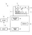
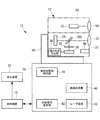
図1は、本発明の第1実施形態に係る監視装置10の全体構成を示すブロック図である。監視装置10は、例えば船舶や船舶等における障害物等の物体の監視を行う。
図1に示されるように、本第1実施形態に係る監視装置10は、レーザ送受信部12、旋回台14、レーダ制御部16、制御装置18、及び表示装置20を備えている。
[First Embodiment]
FIG. 1 is a block diagram showing the overall configuration of a
As shown in FIG. 1, the
レーザ送受信部12は、筐体内部に受光部21を備えている。
受光部21は、例えば、ズームレンズ22、撮像素子24、位置検出素子26(PSD:Position Sensitivity Diodes)、ミラー28A、及び図心位置算出部30を備えている。レーザ送受信部12は、旋回台14によりその回転角及び迎角が所望の角度に調節される。
The laser transmitting / receiving
The
ズームレンズ22は、物体により反射された反射光を集光して、ミラー28Aに導く。
The
撮像素子24は、物体を撮像する例えばCCDイメージセンサであり、複数の受光素子が2次元状に配列されたセンサである。なお、撮像素子24としてCMOSイメージセンサ等他のイメージセンサを用いてもよい。
The
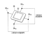
位置検出素子26は、単一の受光素子であって、図2に示されるように、光(入射光)が入射する受光面32、及び受光面32の辺に設けられ、光の入射位置までの抵抗長に応じた信号(例えば電流)を出力する複数の出力端子34X1,34X2,34Y1,34Y2を有する。すなわち、出力端子34X1,34X2は受光面32に入射した入射光のX方向の位置を示す信号を出力し、出力端子34Y1,34Y2は、は受光面32に入射した入射光のY方向の位置を示す信号を出力する。
位置検出素子26の受光面32は、一例として図2に示されるように、矩形であるが、これに限らず、三角形や五角形以上等の多角形であってもよい。さらに、図2に示される出力端子34X1,34X2,34Y1,34Y2の位置も一例であり、これに限られない。
The
The
ミラー28Aは、物体に反射した光が入射され、該光を撮像素子24及び位置検出素子26へ送光する。なお、ミラー28Aは、例えばハーフミラーとされ、ズームレンズ22によって導かれた光を分光し、撮像素子24及び位置検出素子26に同時に送光する。
The mirror 28 </ b> A receives the light reflected by the object and transmits the light to the
図心位置算出部30は、位置検出素子26が有する複数の出力端子34から出力された信号に基づいて、位置検出素子26に入射した光の受光面32における図心位置を算出する。
The centroid
レーダ制御部16は、制御装置18から供給される各種制御信号に基づいて、上記レーザ送受信部12が備える受光部21及び旋回台14を制御するために、旋回台駆動制御部40、制御信号変換部42、及び画像処理部44を備えている。
The
旋回台駆動制御部40は、図心位置算出部30で算出された図心位置が制御信号として入力され、該制御信号に基づいてレーザ送受信部12を旋回させる。
The swivel base
制御信号変換部42は、制御装置18から出力された制御信号が入力され、レーダ制御部16が備える各種機能を動作させるための制御信号に変換する。
The control
画像処理部44は、撮像素子24から出力された画像信号が入力され、画像信号に対して各種画像処理を行う。
The
制御装置18は、レーダ制御部16を制御するための各種制御信号を生成し、生成した各種制御信号をレーダ制御部16に出力するとともに、レーダ制御部16から供給される監視結果を表示装置20へ出力する。
The
表示装置20は、制御装置18から入力される監視結果(例えば画像処理部44から出力された画像処理後の画像信号)を表示する表示モニタ(図示略)を備えている。
The
上述したレーダ制御部16及び制御装置18は、例えば、CPU(Central Processing Unit)、HD(Hard Disc)、ROM(Read Only Memory)、及びRAM(Random Access Memory)等を備えるコンピュータシステムを内蔵している。後述の各種機能を実現するための一連の処理過程は、プログラムの形式でHD又はROM等に記録されており、このプログラムをCPUがRAM等に読み出して、情報の加工・演算処理を実行することにより、後述の各種機能を実現させる。
The
次に、本第1実施形態に係る監視装置10の作用について説明する。
Next, the operation of the
監視装置10が、物体の監視を行う場合において、制御装置18は、ズームレンズ22によって受光部21内に導かれた光を用いて、位置検出素子26による物体の位置検出を行わせる。位置検出素子26が有する出力端子34X1,34X2,34Y1,34Y2は、各々、受光面32に入射した光の入射位置までの抵抗長に応じた電流IX1,IX2,IY1,IY2を図心位置算出部30へ出力する。
When the
図3を参照して、図心位置算出部30による光の受光面32における図心位置の算出について説明する。
出力端子34X1,34X2から出力される電流IX1,IX2は、入射光の受光面32におけるx方向の位置を示す。一方、出力端子34Y1,34Y2から出力される電流IY1,IY2は、入射光の受光面32におけるy方向の位置を示す。
そして、入射光の図心位置をx,yとし、x方向の抵抗長をLxとし、y方向の抵抗長をLyとすると、図心位置x,yは、下記(1)式を用いて算出される。算出された図心位置x,yが監視する物体の位置を示すこととなる。
Currents I X1 and I X2 output from the output terminals 34 X1 and 34 X2 indicate the position of the incident light in the x direction on the
Then, assuming that the centroid position of incident light is x, y, the resistance length in the x direction is L x, and the resistance length in the y direction is L y , the centroid positions x and y use the following formula (1). Is calculated. The calculated centroid position x, y indicates the position of the object to be monitored.
図心位置算出部30によって算出された図心位置x,yは、制御信号として旋回台駆動制御部40へ出力される。
The centroid positions x and y calculated by the centroid
旋回台駆動制御部40は、入力された図心位置x,yが受光面32の所定位置となるように、旋回台14によって受光部21を有するレーザ送受信部12を旋回させる。なお、所定位置とは、例えば受光面32の中心位置(x=0,y=0)である。これによって、監視装置10による監視する物体に対する追尾が行われることとなる。なお、監視する物体は、撮像素子24によって撮像されて表示装置20が備える表示モニタに表示される。
The swivel base
ここで、撮像素子24は、鮮明な画像を取得できるが、物体の位置を特定するための画像処理を必要とし、画像処理を行うための情報処理装置等の機材を必要とする。さらに、画像処理の結果を用いて旋回台14の制御等が行われるため、監視する物体に対する追尾が遅れる場合があった。
一方、位置検出素子26により物体の位置を特定するためには、出力端子34X1,34X2,34Y1,34Y2から出力される複数の電流値に基づいて、入射光の受光面32における図心位置を算出する。図心位置は、(1)式に基づいて簡易に算出できるので、本第1実施形態に係る監視装置10は、複雑な画像処理を必要とせず、簡易かつ迅速に監視する物体の位置を特定できる。
Here, the
On the other hand, in order to specify the position of the object by the
以上説明したように、本第1実施形態に係る監視装置10は、物体を撮像する撮像素子24と、光が入射する受光面32、及び受光面32の辺に設けられ、光の入射位置までの抵抗長に応じた信号を出力する複数の出力端子34X1,34X2,34Y1,34Y2を有する位置検出素子26と、物体に反射した光が入射され、該光を撮像素子24及び位置検出素子26へ送光するミラー28Aとを備える。そして、監視装置10は、図心位置算出部30によって、位置検出素子26が有する複数の出力端子34X1,34X2,34Y1,34Y2から出力された電流に基づいて、位置検出素子26に入射した光の受光面32における図心位置を算出する。
従って、本第1実施形態に係る監視装置10は、簡易な構成で物体の確実な追尾を可能とする
As described above, the
Therefore, the
〔第2実施形態〕
以下、本発明の第2実施形態について説明する。
[Second Embodiment]
Hereinafter, a second embodiment of the present invention will be described.
図4は、本第2実施形態に係る監視装置10の構成を示す。なお、図4における図1と同一の構成部分については図1と同一の符号を付して、その説明を省略する。
FIG. 4 shows a configuration of the
本第2実施形態に係る監視装置10は、レーザ送受信部12に送光部50を備える。これにより、レーザ送受信部12はレーザレーダとして機能することとなる。
送光部50は、レーザ光を発するレーザ発振器52、レーザ発振器52から発せられたレーザ光を物体へ照射させる送光レンズ54、及び送光レンズ54の角度を調整するための送光レンズアクチュエータ(図示略)を備えている。
The
The
レーザ発振器52は、例えば、半導体レーザなどの小型のレーザであり、レーダ制御部16内のレーザ電源56から電源供給をうけ、レーザ光を出射する。また、送光レンズアクチュエータは、レーダ制御部16から供給される制御信号に基づいて、送光レンズ54の位置を調整する。これにより、レーザ送受信部12は、送光レンズ54に入射されるレーザ光の角度を調整し、所望の範囲に、レーザ光を出射させることが可能となる。なお、レーザ光は、例えば不可視光であり、撮像素子24及び位置検出素子26は不可視光に感度を有する。
The
次に、本第2実施形態に係る監視装置10の作用について説明する。
Next, the operation of the
まず、監視時において、制御装置18は、レーザ発振器52にレーザ光を発振させて送光部50からレーザ光を監視する物体へ送光させる。
図5は、本第2実施形態に係る監視装置10によって、物体にレーザ光が照射された場合において、位置検出素子26の受光面32に投影される範囲の一例を示した模式図である。図5の例に示されるように、レーザ光は、送光レンズ54によって発散され、受光面32の投影範囲よりも広い範囲を照射範囲とする。
なお、図5に示されるレーザ光は、照射範囲が円形とされているが、これに限らず、照射範囲が楕円形、矩形等他の形状であってもよい。
First, at the time of monitoring, the
FIG. 5 is a schematic diagram showing an example of a range projected on the
The laser beam shown in FIG. 5 has a circular irradiation range, but the present invention is not limited to this, and the irradiation range may be other shapes such as an ellipse or a rectangle.
送光部50から出射されたレーザ光が物体に到達し、物体により反射されたレーザ光は、位置検出素子26に入射する。
位置検出素子26は、ガイド光が受光面32に入射した入射位置に応じた電流IX1,IX2,IY1,IY2を複数の出力端子34X1,34X2,34Y1,34Y2から出力する。
図心位置算出部30は、出力端子から出力された電流IX1,IX2,IY1,IY2に基づいて受光面32に入射したレーザ光の図心位置を算出する。
そして、旋回台駆動制御部40は、図心位置算出部30で算出された図心位置と受光部21の中心位置との差がなくなるように、レーザ送受信部12を旋回させる。
The laser light emitted from the
The
The centroid
Then, the turntable
このように、本第2実施形態に係る監視装置10は、レーザ光が物体に照射されることとなるので、闇夜、雨、霧等の悪環境でも、物体を監視でき、レーザ光を不可視光とすることで、相手に気づかれずに監視することができる。
As described above, since the
〔第3実施形態〕
以下、本発明の第3実施形態について説明する。
[Third Embodiment]
Hereinafter, a third embodiment of the present invention will be described.
図6は、本第3実施形態に係る監視装置10の構成を示す。なお、図6における図4と同一の構成部分については図4と同一の符号を付して、その説明を省略する。
FIG. 6 shows a configuration of the
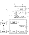
本第3実施形態に係る監視装置10は、レーザ送受信部12にガイド光照射部60及びフィルタ62を備える。
The
ガイド光照射部60は、送光部50から出射されるレーザ光と異なる波長であり、かつ照射領域がレーザ光の照射領域よりも狭いガイド光を、物体に反射して位置検出素子26の受光面32の所定位置に入射するように出射する。なお、所定位置とは、受光面32の中心位置(x=0,y=0)である。
The guide
フィルタ62は、レーザ光の波長を通過させずにガイド光の波長を通過させ、位置検出素子26にガイド光を入射させる。
The
次に、本第3実施形態に係る監視装置10の作用について説明する。
Next, the operation of the
まず、監視時において、制御装置18は、レーザ発振器52にレーザ光を発振させて送光部50からレーザ光を監視する物体へ送光させる共に、ガイド光照射部60に位置検出素子26の受光面32の中心位置に向けてガイド光を照射させる。レーザ送受信部12は、ガイド光が監視する物体に照射されるように旋回台14によって旋回される。
First, at the time of monitoring, the
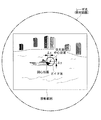
また、図7に示されるように、ガイド光の照射領域は、レーザ光の照射領域よりも狭く、かつ監視する物体の主要部分(例えば物体の半分以上)が含まれる広さとされている。 Further, as shown in FIG. 7, the irradiation area of the guide light is narrower than the irradiation area of the laser light, and is wide enough to include the main part of the object to be monitored (for example, more than half of the object).
そして、物体により反射されたレーザ光及びガイド光がズームレンズ22を介して、受光部21に導入される。しかし、フィルタ62によってガイド光のみが弁別され、ガイド光のみが位置検出素子26に入射する。
Then, the laser light and the guide light reflected by the object are introduced into the
位置検出素子26は、ガイド光が受光面32に入射した入射位置に応じた電流IX1,IX2,IY1,IY2を出力端子34X1,34X2,34Y1,34Y2から出力する。
図心位置算出部30は、出力された電流IX1,IX2,IY1,IY2に基づいて受光面32に入射したレーザ光の図心位置を算出する。
The
The centroid
ここで、レーザ光のみで物体を監視すると、背景となる他の物体にレーザ光が反射する場合がある。この場合、位置検出素子26に入射する入射光が、監視する物体に反射された光であるか、監視対象ではない他の物体に反射された光なのか区別できない。
このため、ガイド光を監視する物体に照射し続けることによって、監視する物体と他の物体とが区別されることとなる。
Here, when the object is monitored only with the laser beam, the laser beam may be reflected to another object as a background. In this case, it cannot be distinguished whether the incident light incident on the
For this reason, the object to be monitored is distinguished from other objects by continuing to irradiate the object to be monitored with the guide light.
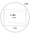
図8は、本第3実施形態に係る監視装置10によって、物体にレーザ光及びガイド光が照射された場合であって、物体が移動した場合を示した模式図である。
監視する物体が移動すると、ガイド光は監視する物体に対して広さを有しているので、図8に示されるように、位置検出素子26の受光部21に入射したガイド光の図心位置が変化する。
そして、旋回台駆動制御部40は、図心位置算出部30で算出された図心位置と受光部21の中心位置との差Δx,Δyが0となるように、レーザ送受信部12を旋回させる。
FIG. 8 is a schematic diagram showing a case where the object is irradiated with laser light and guide light by the
When the object to be monitored moves, the guide light has a width relative to the object to be monitored. Therefore, as shown in FIG. 8, the centroid position of the guide light incident on the
Then, the turntable
このように、第3実施形態に係る監視装置10は、物体以外でレーザ光が強く反射し、監視する物体とその他の物体との判別がレーザ光では困難となっても、ガイド光が監視する物体に照射され、ガイド光によって物体を監視することとなるので、監視する物体をより確実に追尾できる。
As described above, the
なお、図7,8に示されるガイド光は、照射範囲が円形とされているが、これに限らず、照射範囲が楕円形、矩形等他の形状であってもよい。 In addition, although the irradiation range of the guide light shown in FIGS. 7 and 8 is circular, the irradiation range is not limited to this and may be other shapes such as an ellipse and a rectangle.
図9は、第3実施形態に係るガイド光の他の例を示した模式図である。
図9に示されるように、ガイド光は、レーザ光の照射領域よりも狭い照射領域内で各々が重ならないように複数出射されてもよい。なお、図9の例に示される複数のガイド光は、照射領域が矩形とされ、該照射領域内で縦横にマトリクス状に配列されているが、これに限らず、例えば、照射領域が円形とされ、同心円状に複数のガイド光が配列されてもよいし、照射領域が三角形や五角形以上の多角形とされてもよい。
これによれば、ガイド光の照射領域の中心位置から監視する物体がずれても、複数出射されるガイド光の何れかが物体を照射し続けることとなるので、監視する物体をより確実に追尾できる。
FIG. 9 is a schematic diagram illustrating another example of guide light according to the third embodiment.
As shown in FIG. 9, a plurality of guide lights may be emitted so as not to overlap each other in an irradiation area narrower than the irradiation area of the laser light. Note that the plurality of guide lights shown in the example of FIG. 9 have a rectangular irradiation area and are arranged in a matrix in the vertical and horizontal directions within the irradiation area. In addition, a plurality of guide lights may be arranged concentrically, and the irradiation area may be a triangle or a pentagon or more polygon.
According to this, even if the object to be monitored deviates from the center position of the irradiation area of the guide light, any of the plurality of emitted guide lights will continue to irradiate the object, so that the object to be monitored can be tracked more reliably it can.
〔第4実施形態〕
以下、本発明の第4実施形態について説明する。
[Fourth Embodiment]
The fourth embodiment of the present invention will be described below.
図10は、本第4実施形態に係る監視装置10の構成を示す。なお、図10における図4と同一の構成部分については図4と同一の符号を付して、その説明を省略する。
FIG. 10 shows a configuration of the
本第4実施形態に係る監視装置10は、送光部50が備えるレーザ発振器52からレーザ光をパルス状に出射し、レーザ送受信部12の受光部21に高速ゲート装置70を備える。
The
高速ゲート装置70は、レーダ制御部16に設けられた高速ゲート装置制御部72により駆動されるものであり、ズームレンズ22により導かれた光を撮像素子24及び位置検出素子26に取り込むシャッタとして機能する。すなわち、位置検出素子26は、送光部50から出射されたレーザ光が物体に到達し、物体により反射された反射光が到達するタイミングに合わせてシャッタが開かれ、該反射光が受光面32に入射した入射位置に応じた信号を複数の出力端子から出力する。
The high-
ズームレンズ22は、送光部50から発せられ、目標物により反射された反射光を集光して、高速ゲート装置70に導く。
The
レーダ制御部16は、高速ゲート装置制御部72及び同期部74を備える。
The
同期部74は、制御装置18から制御信号変換部42を経由して入力された同期制御信号に基づいて、レーザ光の送光と受光の同期を取るための同期信号を生成し、レーザ電源56及び高速ゲート装置制御部72に出力する。
The
高速ゲート装置制御部72は、制御装置18から制御信号変換部42を経由して入力されたシャッタ駆動信号、及び同期部74から入力された同期信号に基づいて、高速ゲート装置70を駆動させる。
The high-speed gate
レーザ電源56は、同期部74から供給された同期信号に基づいて、送光部50が備えるレーザ発振器52の動作信号を生成し、動作信号に基づいてレーザ発振器52を駆動する。
The
次に、本第4実施形態に係る監視装置10の作用について説明する。
Next, the operation of the
まず、監視時において、制御装置18は、レーザ光を所定のタイミングで出射させるために必要となる同期制御信号、所定のタイミングで出射したレーザ光が所定の物体に到達し、反射された反射光のみを受光部21が備える撮像素子24及び位置検出素子26に取り込むためのシャッタ駆動信号等を生成し、これらをレーダ制御部16に出力する。
First, at the time of monitoring, the
制御装置18から出力された同期制御信号及びシャッタ駆動信号は、レーダ制御部16内の制御信号変換部42を経由して、同期部74、高速ゲート装置制御部72へそれぞれ出力される。
同期部74は、同期制御信号に基づいて同期信号を生成し、レーザ電源56及び高速ゲート装置制御部72に出力する。高速ゲート装置制御部72は、シャッタ駆動信号及び同期信号に基づいて高速ゲート装置70を駆動する。レーザ電源56は、同期信号に基づいてレーザ発振器52を駆動する。
The synchronization control signal and the shutter drive signal output from the
The
これにより、所定のタイミングでパルス状のレーザ光がレーザ発振器52から出射される。出射されたレーザ光は、送光レンズ54により所定の範囲を有する照射領域に発散されて出射され、更に、照射領域内に存在する物体により反射された上記レーザ光が受光部21に導かれることとなる。この場合において、高速ゲート装置制御部72がシャッタ駆動信号に基づいて高速ゲート装置70を駆動することにより、監視する物体によって反射されてきたレーザ光のみを撮像素子24及ぶ位置検出素子26に入射させることが可能となる。すなわち、監視装置10と物体との間及び物体よりもより離れた場所に位置する他の物体である背景等に反射したレーザ光は、撮像素子24及び位置検出素子26に入射されない。
Thereby, a pulsed laser beam is emitted from the
位置検出素子26は、送光部50から出射されたレーザ光が物体に到達し、監視する物体により反射された反射光が到達するタイミングに合わせて高速ゲート装置70のシャッタ機能によるシャッタが開かれ、該反射したレーザ光が受光面32に入射した入射位置に応じた電流IX1,IX2,IY1,IY2を複数の出力端子34X1,34X2,34Y1,34Y2から出力する。
図心位置算出部30は、出力端子から出力された電流IX1,IX2,IY1,IY2に基づいて受光面32に入射したレーザ光の図心位置を算出する。
そして、旋回台駆動制御部40は、図心位置算出部30で算出された図心位置と受光部21の中心位置との差がなくなるように、レーザ送受信部12を旋回させる。
In the
The centroid
Then, the turntable
以上説明したように、本第4実施形態に係る監視装置10は、送光部50から出射されたパルス状のレーザ光が監視する物体に到達し、物体に反射したレーザ光が戻ってくるタイミングで位置検出素子26にレーザ光が入射されるので、監視する物体に反射したレーザ光の反射光のみ位置検出素子26に入射させることができる。
As described above, in the
〔第5実施形態〕
以下、本発明の第5実施形態について説明する。
[Fifth Embodiment]
The fifth embodiment of the present invention will be described below.
なお、本第5実施形態に係る監視装置10の構成は、図10に示す第4実施形態に係る監視装置10の構成と同様であるので説明を省略する。
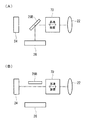
ただし、本第5実施形態に係るミラー28Bは、ズームレンズ22によって導かれたレーザ光を、位置検出素子26へ反射させる一方、撮像素子24へは入射させない。また、ミラー28Bは、ズームレンズ22から撮像素子24に至る光路から移動可能とされている。
The configuration of the
However, the mirror 28 </ b> B according to the fifth embodiment reflects the laser light guided by the
次に、本第5実施形態に係る監視装置10の作用について説明する。
Next, the operation of the
本第5実施形態に係る監視装置10は、送光部50に備えられるレーザ発振器52が撮像素子24のフレームレートの2倍の周期で、レーザ光をパルス状に出射する。具体的には、CCDイメージセンサである撮像素子24のフレームレートを一例として30Hzとすると、レーザ発振器52が60Hzのレーザ光を出射する。
In the
そして、ミラー28Bは、パルス状に出射されるレーザ光に同期させて、撮像素子24と位置検出素子26へ導かれてきた光を交互に送光させる。
図11(A)に示されるように、ミラー28Bは、ズームレンズ22によって導かれたレーザ光を、反射させ位置検出素子26に送光する。そして、ズームレンズ22によって導かれたレーザ光を撮像素子24へ送光させる場合、図11(B)に示されるように、ミラー28Bは、レーザ光の光路から移動する。これによって、撮像素子24に光が入射することとなる。なお、ミラー28Bは、レーザ光に同期して駆動するモータによって移動される。
The
As shown in FIG. 11A, the mirror 28 </ b> B reflects the laser light guided by the
従って、本第5実施形態に係る監視装置10は、撮像素子24のフレームレートで撮像素子24と位置検出素子26とに光が入射するので、光量の低下を伴うことなく、撮像素子24による物体の撮像及び位置検出素子26による物体の位置の検出を同時に行え、かつ撮像素子24による動画の撮影も同時に行うことができる。
Therefore, the
〔第6実施形態〕
以下、本発明の第6実施形態について説明する。
[Sixth Embodiment]
The sixth embodiment of the present invention will be described below.
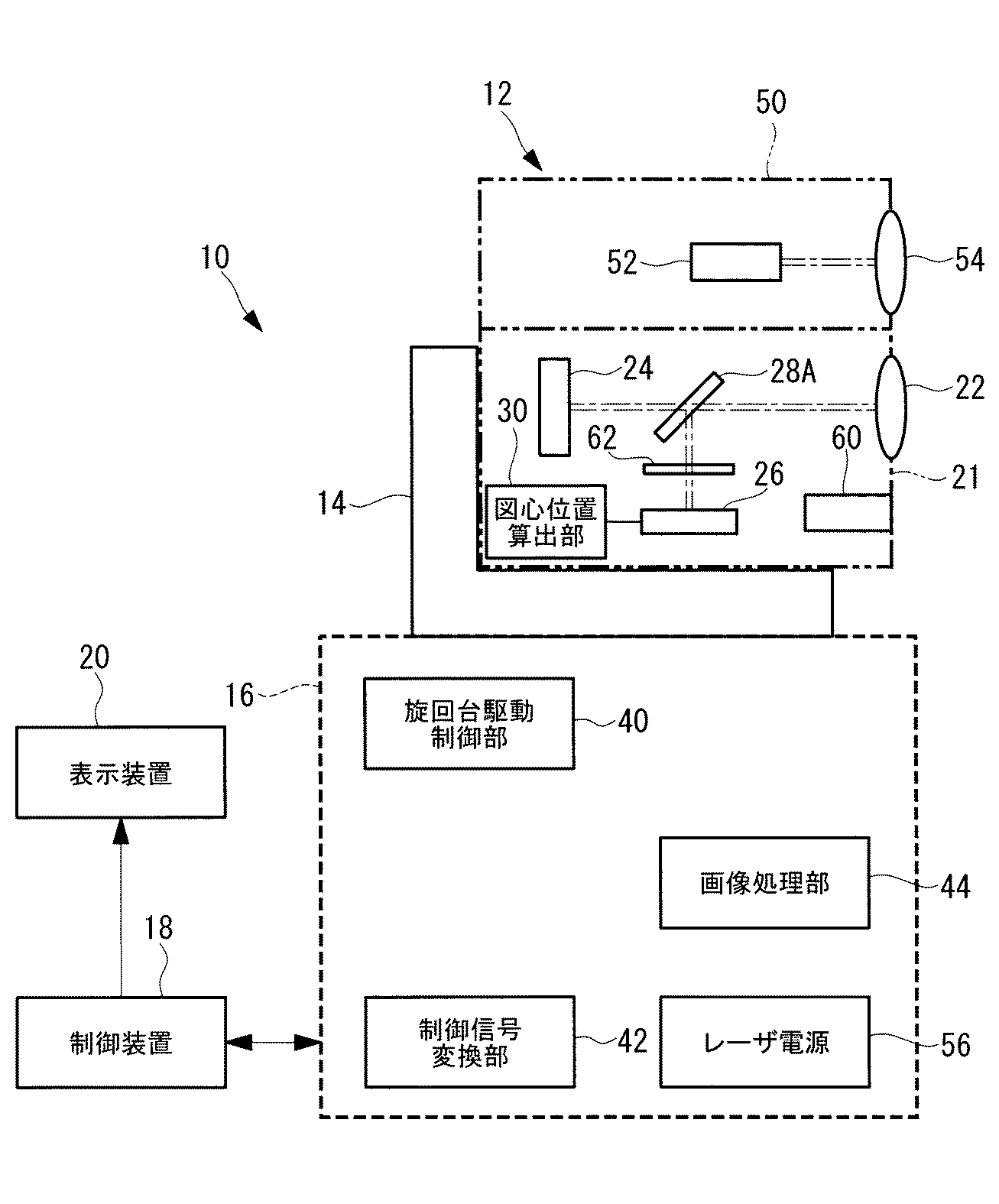
図12は、本第6実施形態に係る監視装置10の構成を示す。なお、図12における図6と同一の構成部分については図6と同一の符号を付して、その説明を省略する。
本第6実施形態に係る監視装置10は、受光部21に撮像素子を備えていない。このため、受光部21内に導かれた光を位置検出素子26及び撮像素子へ送光させるミラーといった入射光送光手段も備えない。
また、受光部21に撮像素子を備えていないことに伴い、レーダ制御部16は、画像処理装置を備えない。
なお、本第6実施形態に係る監視装置10の作用は、上述した第1実施形態から第3実施形態と同様であるため、その説明を省略する。
FIG. 12 shows the configuration of the
The
In addition, the
In addition, since the effect | action of the
以上、本発明を、上記各実施形態を用いて説明したが、本発明の技術的範囲は上記実施形態に記載の範囲には限定されない。発明の要旨を逸脱しない範囲で上記各実施形態に多様な変更または改良を加えることができ、該変更または改良を加えた形態も本発明の技術的範囲に含まれる。 As mentioned above, although this invention was demonstrated using said each embodiment, the technical scope of this invention is not limited to the range as described in the said embodiment. Various changes or improvements can be added to the above-described embodiments without departing from the gist of the invention, and embodiments to which the changes or improvements are added are also included in the technical scope of the present invention.
例えば、上記第1実施形態から第5実施形態では、ズームレンズ22の後方に撮像素子が位置し、ズームレンズ22の斜め下後方に位置検出素子26が位置する形態について説明したが、本発明は、これに限定されるものではなく、例えば、撮像素子24と位置検出素子26の位置を逆とする形態としてもよい。
For example, in the first to fifth embodiments described above, the imaging element is located behind the
10 監視装置
21 受光部
24 撮像素子
26 位置検出素子
28A ミラー
28B ミラー
30 図心位置算出部
32 受光面
34 出力端子
50 送光部
60 ガイド光照射部
62 フィルタ
DESCRIPTION OF
Claims (10)
光が入射する受光面、及び該受光面の辺に設けられ、光の入射位置までの抵抗長に応じた信号を出力する複数の出力端子を有する位置検出素子と、
物体に反射した光が入射され、該光を前記撮像素子及び前記位置検出素子の少なくとも一方へ送光する入射光送光手段と、
前記位置検出素子が有する複数の前記出力端子から出力された前記信号に基づいて、前記位置検出素子に入射した光の前記受光面における図心位置を算出する算出手段と、
を備えた監視装置。 An image sensor for imaging an object;
A light receiving surface on which light is incident, and a position detection element that is provided on a side of the light receiving surface and has a plurality of output terminals that output signals according to the resistance length to the light incident position;
Incident light transmitting means for receiving light reflected by an object and transmitting the light to at least one of the imaging element and the position detecting element;
Calculation means for calculating a centroid position of the light incident on the position detection element on the light receiving surface based on the signals output from the plurality of output terminals of the position detection element;
Monitoring device.
前記位置検出素子は、前記送光手段から出射された前記レーザ光が物体に到達し、前記物体により反射された光が前記受光面に入射する請求項1記載の監視装置。 Comprising a light transmitting means for emitting laser light;
The monitoring apparatus according to claim 1, wherein the position detection element is configured such that the laser light emitted from the light transmitting unit reaches an object, and light reflected by the object is incident on the light receiving surface.
前記レーザ光の波長を通過させずに前記ガイド光の波長を通過させ、前記位置検出素子に前記ガイド光を入射させるフィルタと、
を備えた請求項2記載の監視装置。 Guide light having a wavelength different from that of the laser light emitted from the light transmitting means and having an irradiation area narrower than the irradiation area of the laser light is reflected by an object and incident on a predetermined position of the light receiving surface. Exiting guide light irradiation means;
A filter that allows the wavelength of the guide light to pass without passing the wavelength of the laser light, and makes the guide light incident on the position detection element;
The monitoring device according to claim 2, further comprising:
前記位置検出素子は、前記送光手段から出射された前記レーザ光が物体に到達し、前記物体により反射された反射光が到達するタイミングに合わせてシャッタが開かれ、該反射光が受光面に入射した入射位置に応じた信号を複数の出力端子から出力する請求項2記載の監視装置。 The light transmitting means emits the laser light in a pulse shape,
The position detection element is configured such that the laser light emitted from the light transmitting means reaches the object, the shutter is opened at a timing when the reflected light reflected by the object arrives, and the reflected light is incident on the light receiving surface. The monitoring apparatus according to claim 2, wherein a signal corresponding to the incident position is output from a plurality of output terminals.
前記入射光送光手段は、前記位置検出素子又は前記撮像素子へ光を送光するミラーであり、パルス状に出射される前記レーザ光に同期して、前記撮像素子と前記位置検出素子とへ交互に光を送光させる請求項5記載の監視装置。 The light transmitting means emits a pulsed laser beam at a cycle twice the frame rate of the image sensor,
The incident light transmitting means is a mirror that transmits light to the position detection element or the imaging element, and is synchronized with the laser beam emitted in a pulse shape to the imaging element and the position detection element. The monitoring device according to claim 5, wherein light is alternately transmitted.
前記送光手段から出射された前記レーザ光が物体に到達し、前記物体により反射された光が入射する受光面、及び該受光面の辺に設けられ、光の入射位置までの抵抗長に応じた信号を出力する複数の出力端子を有する位置検出素子と、
前記位置検出素子が有する複数の前記出力端子から出力された前記信号に基づいて、前記位置検出素子に入射した光の受光面における図心位置を算出する算出手段と、
を備えた監視装置。 Light transmitting means for emitting laser light;
Depending on the light receiving surface on which the laser light emitted from the light transmitting means reaches the object and the light reflected by the object is incident, and on the side of the light receiving surface, depending on the resistance length to the light incident position A position detection element having a plurality of output terminals for outputting the received signal;
Calculation means for calculating a centroid position on a light receiving surface of light incident on the position detection element based on the signals output from the plurality of output terminals of the position detection element;
Monitoring device.
前記レーザ光の波長を通過させずに前記ガイド光の波長を通過させ、前記位置検出素子へ前記ガイド光を入射させるフィルタと、
を備えた請求項7記載の監視装置。 Guide light having a wavelength different from that of the laser light emitted from the light transmitting means and having an irradiation area narrower than the irradiation area of the laser light, and light reflected by the guide light on an object is a predetermined position on the light receiving surface. Guide light irradiating means for emitting light so as to be incident on
A filter that allows the wavelength of the guide light to pass without passing the wavelength of the laser light, and makes the guide light incident on the position detection element;
The monitoring device according to claim 7, further comprising:
前記位置検出素子が有する複数の前記出力端子から出力された前記信号に基づいて、前記位置検出素子に入射した光の前記受光面における図心位置を算出する第1工程と、
前記第1工程で算出した図心位置が前記位置検出素子の前記受光面の所定位置となるように、前記位置検出素子が設けられた筐体を旋回させて物体を追尾する第2工程と、
を含む監視方法。 An image sensor that images an object, a light receiving surface on which light is incident, and a position detection element that is provided on a side of the light receiving surface and has a plurality of output terminals that output signals according to the resistance length to the light incident position; A monitoring method using a monitoring device comprising incident light transmitting means for receiving light reflected by an object and transmitting the light to at least one of the imaging element and the position detecting element,
A first step of calculating a centroid position on the light receiving surface of light incident on the position detection element based on the signals output from the plurality of output terminals of the position detection element;
A second step of tracking the object by turning the casing provided with the position detection element so that the centroid position calculated in the first step is a predetermined position of the light receiving surface of the position detection element;
Including monitoring methods.
前記位置検出素子が有する複数の前記出力端子から出力された前記信号に基づいて、前記位置検出素子に入射した光の前記受光面における図心位置を算出する第1工程と、
前記第1工程で算出した図心位置が前記位置検出素子の前記受光面の所定位置となるように、前記位置検出素子が設けられた筐体を旋回させて物体を追尾する第2工程と、
を含む監視方法。
A light transmitting means for emitting laser light; and a light receiving surface on which the laser light emitted from the light transmitting means reaches an object and the light reflected by the object enters, and a side of the light receiving surface, A position detection element having a plurality of output terminals for outputting a signal corresponding to the resistance length to the incident position of light, and a monitoring method using a monitoring device comprising:
A first step of calculating a centroid position on the light receiving surface of light incident on the position detection element based on the signals output from the plurality of output terminals of the position detection element;
A second step of tracking the object by turning the casing provided with the position detection element so that the centroid position calculated in the first step is a predetermined position of the light receiving surface of the position detection element;
Including monitoring methods.
Priority Applications (1)
| Application Number | Priority Date | Filing Date | Title |
|---|---|---|---|
| JP2012044820A JP6129475B2 (en) | 2012-02-29 | 2012-02-29 | Monitoring device and monitoring method |
Applications Claiming Priority (1)
| Application Number | Priority Date | Filing Date | Title |
|---|---|---|---|
| JP2012044820A JP6129475B2 (en) | 2012-02-29 | 2012-02-29 | Monitoring device and monitoring method |
Publications (2)
| Publication Number | Publication Date |
|---|---|
| JP2013181794A true JP2013181794A (en) | 2013-09-12 |
| JP6129475B2 JP6129475B2 (en) | 2017-05-17 |
Family
ID=49272554
Family Applications (1)
| Application Number | Title | Priority Date | Filing Date |
|---|---|---|---|
| JP2012044820A Active JP6129475B2 (en) | 2012-02-29 | 2012-02-29 | Monitoring device and monitoring method |
Country Status (1)
| Country | Link |
|---|---|
| JP (1) | JP6129475B2 (en) |
Cited By (1)
| Publication number | Priority date | Publication date | Assignee | Title |
|---|---|---|---|---|
| JP2022172185A (en) * | 2019-08-06 | 2022-11-15 | 直之 村上 | Computer eye (pceye) |
Citations (10)
| Publication number | Priority date | Publication date | Assignee | Title |
|---|---|---|---|---|
| JPH05133723A (en) * | 1991-11-13 | 1993-05-28 | Sumitomo Electric Ind Ltd | Method and device for measuring separateness with laser beam |
| JP2000162307A (en) * | 1998-11-30 | 2000-06-16 | Mitsubishi Heavy Ind Ltd | Laser tracking apparatus for locating position of reactor vessel-inspecting robot |
| JP2003149717A (en) * | 2001-11-19 | 2003-05-21 | Mitsubishi Heavy Ind Ltd | Method and device for image pickup |
| JP2004170356A (en) * | 2002-11-22 | 2004-06-17 | Topcon Corp | Automatic reflector tracking device |
| JP2005229253A (en) * | 2004-02-12 | 2005-08-25 | Olympus Corp | Spatial light transmission apparatus |
| JP2006317303A (en) * | 2005-05-13 | 2006-11-24 | Mitsubishi Heavy Ind Ltd | Monitor device |
| JP2009145207A (en) * | 2007-12-14 | 2009-07-02 | Topcon Corp | Surveying device |
| JP2009270954A (en) * | 2008-05-08 | 2009-11-19 | Nikon Vision Co Ltd | Range finder |
| WO2010148526A1 (en) * | 2009-06-23 | 2010-12-29 | Leica Geosystem Ag | Tracking method and measuring system having a laser tracker |
| WO2010148525A1 (en) * | 2009-06-23 | 2010-12-29 | Leica Geosystems Ag | Coordinate measuring device |
-
2012
- 2012-02-29 JP JP2012044820A patent/JP6129475B2/en active Active
Patent Citations (10)
| Publication number | Priority date | Publication date | Assignee | Title |
|---|---|---|---|---|
| JPH05133723A (en) * | 1991-11-13 | 1993-05-28 | Sumitomo Electric Ind Ltd | Method and device for measuring separateness with laser beam |
| JP2000162307A (en) * | 1998-11-30 | 2000-06-16 | Mitsubishi Heavy Ind Ltd | Laser tracking apparatus for locating position of reactor vessel-inspecting robot |
| JP2003149717A (en) * | 2001-11-19 | 2003-05-21 | Mitsubishi Heavy Ind Ltd | Method and device for image pickup |
| JP2004170356A (en) * | 2002-11-22 | 2004-06-17 | Topcon Corp | Automatic reflector tracking device |
| JP2005229253A (en) * | 2004-02-12 | 2005-08-25 | Olympus Corp | Spatial light transmission apparatus |
| JP2006317303A (en) * | 2005-05-13 | 2006-11-24 | Mitsubishi Heavy Ind Ltd | Monitor device |
| JP2009145207A (en) * | 2007-12-14 | 2009-07-02 | Topcon Corp | Surveying device |
| JP2009270954A (en) * | 2008-05-08 | 2009-11-19 | Nikon Vision Co Ltd | Range finder |
| WO2010148526A1 (en) * | 2009-06-23 | 2010-12-29 | Leica Geosystem Ag | Tracking method and measuring system having a laser tracker |
| WO2010148525A1 (en) * | 2009-06-23 | 2010-12-29 | Leica Geosystems Ag | Coordinate measuring device |
Cited By (2)
| Publication number | Priority date | Publication date | Assignee | Title |
|---|---|---|---|---|
| JP2022172185A (en) * | 2019-08-06 | 2022-11-15 | 直之 村上 | Computer eye (pceye) |
| JP7282310B2 (en) | 2019-08-06 | 2023-05-29 | 直之 村上 | Computer eyes (PCEYE) |
Also Published As
| Publication number | Publication date |
|---|---|
| JP6129475B2 (en) | 2017-05-17 |
Similar Documents
| Publication | Publication Date | Title |
|---|---|---|
| US10475312B2 (en) | Monitoring camera and monitoring camera control method | |
| JP4006577B2 (en) | Monitoring device | |
| US20050220450A1 (en) | Image-pickup apparatus and method having distance measuring function | |
| JP5469391B2 (en) | Home door confirmation system | |
| JP2018119942A (en) | Imaging device, method of monitoring the same, and program | |
| JP2009217252A5 (en) | ||
| JP6123377B2 (en) | Image processing apparatus, object detection method, and object detection program | |
| JP2006280938A (en) | Safe detection of eyeball | |
| JP2013207415A (en) | Imaging system and imaging method | |
| JP5682898B2 (en) | Surveillance camera position calibration device | |
| JP2006317304A (en) | Monitor device | |
| JP2015213251A (en) | Behavior analyzer, monitoring system and amusement system | |
| WO2017198038A1 (en) | Laser triangulation system safe for human eyes | |
| JP2005216160A (en) | Image generating apparatus, intruder monitoring apparatus and image generating method | |
| JP2008224620A (en) | Range finder | |
| KR101634129B1 (en) | Moving object tracting control system for pan-tilt camera | |
| JP6129475B2 (en) | Monitoring device and monitoring method | |
| JP5605565B2 (en) | Object identification device and object identification method | |
| JP6828747B2 (en) | Projection system, projection method and program | |
| JP2014055925A (en) | Image processor, object detection method, and object detection program | |
| JP6273682B2 (en) | Image processing apparatus, object detection method, and object detection program | |
| JP2012198802A (en) | Intrusion object detection system | |
| JP5682334B2 (en) | Distance measuring device for moving objects | |
| KR20140000403A (en) | Vehicle velocity detector and method using stereo camera | |
| US10962645B2 (en) | Reception apparatus, reception method, transmission apparatus, transmission method, and communication system |
Legal Events
| Date | Code | Title | Description |
|---|---|---|---|
| A621 | Written request for application examination |
Free format text: JAPANESE INTERMEDIATE CODE: A621 Effective date: 20150210 |
|
| A977 | Report on retrieval |
Free format text: JAPANESE INTERMEDIATE CODE: A971007 Effective date: 20151228 |
|
| A131 | Notification of reasons for refusal |
Free format text: JAPANESE INTERMEDIATE CODE: A131 Effective date: 20160105 |
|
| A521 | Request for written amendment filed |
Free format text: JAPANESE INTERMEDIATE CODE: A523 Effective date: 20160307 |
|
| A131 | Notification of reasons for refusal |
Free format text: JAPANESE INTERMEDIATE CODE: A131 Effective date: 20160809 |
|
| A521 | Request for written amendment filed |
Free format text: JAPANESE INTERMEDIATE CODE: A523 Effective date: 20161011 |
|
| TRDD | Decision of grant or rejection written | ||
| A01 | Written decision to grant a patent or to grant a registration (utility model) |
Free format text: JAPANESE INTERMEDIATE CODE: A01 Effective date: 20170314 |
|
| A61 | First payment of annual fees (during grant procedure) |
Free format text: JAPANESE INTERMEDIATE CODE: A61 Effective date: 20170412 |
|
| R150 | Certificate of patent or registration of utility model |
Ref document number: 6129475 Country of ref document: JP Free format text: JAPANESE INTERMEDIATE CODE: R150 |