JP2013166311A - Image processing apparatus, control method thereof, and program - Google Patents
Image processing apparatus, control method thereof, and program Download PDFInfo
- Publication number
- JP2013166311A JP2013166311A JP2012031042A JP2012031042A JP2013166311A JP 2013166311 A JP2013166311 A JP 2013166311A JP 2012031042 A JP2012031042 A JP 2012031042A JP 2012031042 A JP2012031042 A JP 2012031042A JP 2013166311 A JP2013166311 A JP 2013166311A
- Authority
- JP
- Japan
- Prior art keywords
- image processing
- processing apparatus
- state
- power
- interface
- Prior art date
- Legal status (The legal status is an assumption and is not a legal conclusion. Google has not performed a legal analysis and makes no representation as to the accuracy of the status listed.)
- Pending
Links
Images

Classifications
-
- G—PHYSICS
- G03—PHOTOGRAPHY; CINEMATOGRAPHY; ANALOGOUS TECHNIQUES USING WAVES OTHER THAN OPTICAL WAVES; ELECTROGRAPHY; HOLOGRAPHY
- G03G—ELECTROGRAPHY; ELECTROPHOTOGRAPHY; MAGNETOGRAPHY
- G03G15/00—Apparatus for electrographic processes using a charge pattern
- G03G15/50—Machine control of apparatus for electrographic processes using a charge pattern, e.g. regulating differents parts of the machine, multimode copiers, microprocessor control
- G03G15/5004—Power supply control, e.g. power-saving mode, automatic power turn-off
Landscapes
- Engineering & Computer Science (AREA)
- Microelectronics & Electronic Packaging (AREA)
- Physics & Mathematics (AREA)
- General Physics & Mathematics (AREA)
- Accessory Devices And Overall Control Thereof (AREA)
- Control Or Security For Electrophotography (AREA)
- Power Sources (AREA)
Abstract
Description
本発明は、省電力制御を有する画像処理装置、その制御方法及びプログラムに関するものである。 The present invention relates to an image processing apparatus having power saving control, a control method thereof, and a program.
近年、地球環境保全の観点から、プリンタを含みコンピュータ周辺機器に対しても、エネルギ消費の削減が求められるようになってきている。その際、所定の条件が満たされた周辺機器においては、自動的に低消費電力状態に移行することが、国際的な規格として要求されてきており、省エネルギとユーザの利便性は機器開発の重要なテーマとなっている。 In recent years, from the viewpoint of global environmental conservation, reduction of energy consumption has been demanded for computer peripheral devices including printers. At that time, it has been required as an international standard to automatically shift to a low power consumption state in peripheral devices that satisfy a predetermined condition, and energy saving and user convenience are required for device development. It has become an important theme.
また、機器によっては、低消費電力状態の電力の消費も抑えるために、自動的に電源をOFFする機能を備えた装置も開発されている。特に最近においては、電気代の節約やCO2排出量の削減につながり、ユーザの間でも関心が高まっている。企業においても、企業規模の大小に関わらず、社会的責任として、省エネルギを怠ることはできず、省エネ技術の取り組みも盛んに行われている。 In addition, depending on the device, in order to suppress the power consumption in the low power consumption state, an apparatus having a function of automatically turning off the power has been developed. Particularly recently, this has led to savings in electricity bills and reductions in CO2 emissions, and interest is increasing among users. Even in the enterprise, regardless of the size of the enterprise, as a social responsibility, energy conservation cannot be neglected, and energy-saving technology is being actively pursued.
低消費電力状態への移行の制御方法として、特許文献1には、プリント動作が停止した後における一定時間経過後の制御方法が記載されている。その際、予め印刷を行わない時間帯を設定しておき、スリープモードに移行する際に、前記予め定められた時間帯であれば電源をオフし、そうでなければ、スリープモードに移行する制御を行っている。
As a control method for shifting to the low power consumption state,
しかしながら、上記従来技術には以下に記載する問題がある。上記従来例では、印刷動作が一定時間行われない場合に、スリープモードに移行する制御において、予めプリントを行わない時間帯を設定しておき、当該予め定められた時間帯であれば電源をオフし、そうでなければ、スリープモードに移行する制御を行っている。つまり、スリープモード又は電源オフへ移行する際に、予め印字を行わない時間帯を定め、その時間帯の範囲に基づいた判断しか行っていない。 However, the above prior art has the following problems. In the above conventional example, when the printing operation is not performed for a certain period of time, in the control for shifting to the sleep mode, a time period during which printing is not performed is set in advance, and the power is turned off during the predetermined time period. If not, control for shifting to the sleep mode is performed. That is, when shifting to the sleep mode or power off, a time zone during which printing is not performed is determined in advance, and only a determination based on the range of the time zone is made.
また、一度電源をOFFしてしまうと、スリープ状態で待機させることと異なり、利用可能状態に戻るまでに時間がかかってしまう。特に、ネットワークで使用するプリンタにおいては、多人数で使用するため、利用者全ての使用状況を把握することは困難である。また、機器によっては、電源を入れた時や終了する時に多くの電力を消費してしまうため、短い時間に電源のON/OFFが発生すれば、節電の効果を悪くするといった問題があった。 Also, once the power is turned off, it takes time to return to the usable state, unlike waiting in the sleep state. In particular, since printers used on a network are used by a large number of people, it is difficult to grasp the usage status of all users. In addition, depending on the device, a large amount of power is consumed when the power is turned on or when the power is turned off. Therefore, if the power is turned on / off in a short time, there is a problem that the power saving effect is deteriorated.
本発明は、上述の問題に鑑みて成されたものであり、インタフェースの接続状態に従って電源オフ状態又はスリープ状態への移行処理を行う画像処理装置、その制御方法、及びプログラムを提供することを目的とする。 The present invention has been made in view of the above problems, and an object of the present invention is to provide an image processing apparatus that performs a transition process to a power-off state or a sleep state in accordance with a connection state of an interface, a control method thereof, and a program. And
本発明は、例えば、外部装置を接続するための複数のインタフェースを備える画像処理装置であって、前記画像処理装置の電力状態を変化させる条件を満たした場合に、外部装置との通信が可能な接続状態にあるインタフェースを確認する確認手段と、前記確認手段による確認結果に基づいて、前記画像処理装置がスリープ状態への移行が可能であるか否かを判定する判定手段と、前記判定手段によって前記画像処理装置が所定の電力以下で動作するスリープ状態への移行が可能であると判定されると、該画像処理装置をスリープ状態へ移行させ、前記判定手段によって前記画像処理装置が所定の電力以下で動作するスリープ状態への移行が不可能であると判定されると、該画像処理装置を電源オフに制御する電源制御手段とを備えることを特徴とする。 The present invention is, for example, an image processing apparatus having a plurality of interfaces for connecting an external apparatus, and can communicate with the external apparatus when a condition for changing the power state of the image processing apparatus is satisfied. A confirmation means for confirming an interface in a connected state, a determination means for determining whether or not the image processing apparatus can enter a sleep state based on a confirmation result by the confirmation means, and the determination means When it is determined that the image processing apparatus can be shifted to a sleep state in which the image processing apparatus operates at a predetermined power or less, the image processing apparatus is shifted to a sleep state, and the determination unit causes the image processing apparatus to move to a predetermined power. Power supply control means for controlling the image processing apparatus to be turned off when it is determined that the transition to the sleep state operating in the following is impossible. And butterflies.
本発明は、インタフェースの接続状態に従って電源オフ状態又はスリープ状態への移行処理を行う画像処理装置、その制御方法、及びプログラムを提供できる。 The present invention can provide an image processing apparatus that performs a transition process to a power-off state or a sleep state according to the connection state of an interface, a control method thereof, and a program.
以下、本発明を実施するための形態について図面を用いて説明する。なお、以下の実施形態は特許請求の範囲に係る発明を限定するものでなく、また実施形態で説明されている特徴の組み合わせの全てが発明の解決手段に必須のものとは限らない。 Hereinafter, embodiments for carrying out the present invention will be described with reference to the drawings. The following embodiments do not limit the invention according to the claims, and all combinations of features described in the embodiments are not necessarily essential to the solution means of the invention.
<第1の実施形態>
<画像処理装置の構成>
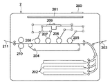
以下では、図1乃至図3、図5を参照して、本発明の第1の実施形態について説明する。まず、図2を参照して、本実施形態における画像処理装置であるプリンタ2の構成例について説明する。図2に示すように、プリンタ2は、操作パネル200、プリンタ制御ユニット201、給紙カセット202、手差しトレイ203、紙送りユニット204、現像ユニット205〜208、レーザスキャナユニット209、定着ユニット210、及び排紙トレイ211を備える。
<First Embodiment>
<Configuration of image processing apparatus>
The first embodiment of the present invention will be described below with reference to FIGS. 1 to 3 and FIG. First, a configuration example of the
プリンタ2は、ホストコンピュータ等の各種外部装置からデータが入力され、記録媒体上への記録を実行する。本実施形態によれば、プリンタ2にはレーザビームプリンタが適用されている。しかしながら、本発明はこれに限定されず、ネットワークに接続可能な画像処理装置であれば適用可能である。
The
プリンタ2には、外部に接続されているホストコンピュータから供給される印字情報(文字コード等)やフォームパターン情報、又は圧縮された画像データなどが入力される。入力された画像データは記憶されると共に、それらの情報に従って対応する文字パターンやフォームパターン等が作成され、又は圧縮された画像データが展開されながら、記憶媒体である記録紙上に画像が形成される。
The
操作パネル200は、各種操作のためのスイッチ及びLED表示器などが配置される。プリンタ制御ユニット(コントローラ)201は、プリンタ2における全体の制御を実行すると共に、ホストコンピュータ等から供給される文字情報などを解析する。このプリンタ制御ユニット201は、主に文字情報を、対応する文字パターンのビデオ信号に変換したり、圧縮された画像データを展開しながらレーザスキャナユニット209に転送したりする。
The
プリントが開始されると、プリンタ2は、給紙カセット202又は手差しトレイ203より記録紙を装置内に給送するための給紙動作を開始する。こうして給紙された記録紙は、紙送りユニット204に送られ、現像ユニット205、206、207、208を順次通過するように搬送される。このとき同時に、プリンタ制御ユニット201で展開された各色毎の画像データは、画像変換処理が行われた後、レーザスキャナユニット209に送られる。
When printing is started, the
レーザスキャナユニット209は、半導体レーザを駆動するための回路であり、入力された画像データに応じて半導体レーザから露光されるレーザ光のON/OFFを切り替える。レーザスキャナユニット209に送られた画像データは、各色毎に、その画像データに基づいて現像ユニット205、206、207、208の感光ドラム上に静電潜像を形成し、各色に対応して現像化され、所望のカラー画像(現像剤像)が形成される。
The
この各色毎の画像データの形成を、記録紙の搬送に同期させることにより、搬送ユニット204を搬送される記録紙上に各色のカラー画像が転写される。また、現像ユニット205、206、207、208には、トナーの残量を検知するセンサーが取り付けられており、トナーの減少に応じて、センサーからの情報が記録部の制御系に送られる。こうしてカラー画像が印刷された記録紙は、定着ユニット210によって熱定着が行われ、排紙トレイ211に排出される。このようなプリンタ2の構成により、各色毎に独立して現像ができるために、非常に高速にプリント画像を得ることができる。
By synchronizing the formation of the image data for each color with the conveyance of the recording paper, the color image of each color is transferred onto the recording paper conveyed by the
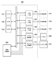
<プリンタ制御ユニットの構成>
次に、図1を参照して、上述のプリンタ2におけるプリンタ制御ユニット201の詳細な構成例について説明する。図1に示すように、プリンタ制御ユニット201は、CPU101、ROM102、RAM103、電源制御部104、USB I/F部106、LAN I/F部107、WLAN I/F部108、パネル制御部109、及びエンジン制御部110を備える。
<Configuration of printer control unit>
Next, a detailed configuration example of the
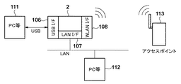
各インタフェース部106、107、108は、外部装置(ホストコンピュータ等)と接続され、外部装置111〜113からコードデータや圧縮されたイメージデータが入力される。各インタフェース部106〜108は、インタフェースの種類に応じて、USB I/F部106、LAN I/F部107、WLAN I/F部108と独立したI/F部を有する。
Each
CPU101は、ROM102に格納された制御プログラムを実行し、プリンタ2を統括的に制御する。RAM103は、ホストコンピュータから送られてきた、プリントするための記録データを蓄えておく領域や、ワークメモリとして、CPU101が各種制御を実行する際に必要な作業領域を提供する。ROM102は、CPU101が実行するための各種プログラム(ファームウェア)を格納する。
The
各インタフェース部106〜108では、インタフェースケーブルで接続され、ホストコンピュータとの制御信号のやり取り、及びデータの送信等を行なう。また、データ受信に関しては、ホストコンピュータから転送された画像データを、RAM103へ格納し、印字する際に、エンジン制御部110に転送する。エンジン制御部110では、RAM103から転送されてくる画像データを、エンジン部105から送られる、同期信号に応じて、画像データを出力する。パネル制御部109は、パネル200に表示する情報を制御したり、パネル200に装備されているスイッチ等の情報を監視している。
Each of the
電源制御部104は、メインの電源スイッチのON/OFFを監視し、装置全体の電源の管理をすると共に、プリンタ制御ユニット201の、各部に対する電源の供給を制御する。本実施形態に係るプリンタ2は、電源制御部104による電源制御状態として、例えば、スタンバイ状態、スリープ状態、及び電源オフ状態に制御される。スタンバイ状態は、プリンタ2が起動した状態であり、印刷命令等を受けると直ぐに印刷を実行可能な状態であり、プリンタ2に含まれる全てのデバイスへ電力が供給されている状態である。また、電源オフ状態は、プリンタ2に含まれる全てのデバイスへの電力供給が停止している状態である。また、スリープ状態は、一定時間が処理が行われていない場合に移行する省電力状態であり、必要最低限の一部のデバイスのみに電力が供給されている状態である。本実施形態に係るプリンタ2は、スリープ状態において、例えば、接続状態にあるインタフェース部のみに電源を供給する。これにより、スリープ状態においても、接続状態にある外部装置からの通信を受け付けることができる。なお、本発明は、このような制御に限定されず、プリンタ2が配置されるシステムの仕様によってスリープ状態時において電源供給を行うデバイスを変更してもよい。また、本実施形態に係るプリンタ2は、スリープ状態において、所定の電力以下に抑えることを目的としているため、所定の電力以下を達成できるのであれば何れのデバイスに電力供給が行われてもよい。
The
<インタフェース>
次に、図5を参照して、プリンタ2と外部装置との接続環境について説明する。各外部装置111〜113は、プリンタ制御ユニット201上の各インタフェースと接続される。例えば、USBで接続する場合には、USB I/F部106にUSBケーブルで外部装置111と接続することにより、当該外部装置111から画像データを受信することにより印字を行うことができる。同様に、LANで接続する場合には、LAN I/F部107と外部装置112を接続し、WLANで接続する場合には、WLAN I/F部108と外部装置113を接続する。これにより、プリンタ2は、各外部装置112、113から画像データを受信して印字を行うことができる。
<Interface>
Next, a connection environment between the
<省電力制御>
次に、図3を参照して、本実施形態における省電力制御の処理手順について説明する。以下で説明する処理は、CPU101及びROM102に格納されている各種プログラム(ファームウェア)によって制御される。
<Power saving control>
Next, with reference to FIG. 3, a processing procedure of power saving control in the present embodiment will be described. Processing described below is controlled by various programs (firmware) stored in the
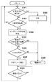
プリンタが印字を終了すると、S301において、CPU101は、次の印字命令が、外部装置(ホストコンピュータ等)から有るか否かを判定する。連続した印字命令があればS302進み、CPU101は、次の印字を開始して、印字が終了すると、再びS301に戻る。
When the printer finishes printing, in S301, the
一方、S301で連続した印字がないと判定するとS303に進み、CPU101は、印字が終了してからの経過時間が、予め設定された時間を超えているか否かを判定する。ここで、予め設定した時間を経過していなければ、S301に戻り、印字命令が来ていないか否かの判定が行われる。つまり、ここでは、CPU101は、プリンタ2において最後に処理が実行されてからの経過時間が一定時間を超えたか否かを判定している。S303の経過時間をカウントしているカウンタをクリアする条件として、カートリッジの交換や、ドアオープン等の操作が含まれる。なお、S301では、経過時間が予め設定された時間を超えている否かを判定しているが、本発明は、画像処理装置の電力状態を変化させる条件を満たしたか否かを判定するようにしてもよい。ここで、電力状態を変化させる条件とは、所定の時刻になった場合や、外部装置からリモートでシャットオフコマンドを受信した場合等が挙げられる。
On the other hand, if it is determined in S301 that there is no continuous printing, the process proceeds to S303, in which the
S303で経過時間が予め設定した時間を超えている場合にはS304に進み、CPU101は、USB I/F部106、LAN I/F部107、WLAN I/F部108のうち、現在何れのインタフェースが接続状態であるかを確認し、S305に進む。ここで、外部装置が接続状態にあるとは、プリンタ2が通信可能に当該外部装置と接続されている状態を示す。即ち、物理的に接続されているだけでは、上記外部装置が接続状態にあるとは言えない。S305において、CPU101は、S304の確認結果に従って、複数の外部装置が接続状態にあるか否かを判定する。接続状態にある外部装置が複数存在するのであれば、S308に進み、CPU101は、シャットダウン処理を行った後、電源制御部104によって装置自体のメイン電源を自動的にOFFし、プリンタ2全体の電源を落とす。
If the elapsed time exceeds the preset time in S303, the process proceeds to S304, and the
一方、接続状態にある外部装置が複数存在しない、即ち、1つであればS306に進み、CPU101は、何れのインタフェースが接続状態であるか否かを判定する。さらに、CPU101は、接続状態にあるインタフェースに従って、0.5W(ワット)のスリープ状態(以下では、0.5Wスリープと略記する。)に移行可能か否かを判定する。本実施形態によれば、プリンタ2は、スリープ電力が0.5W以下にできるかの情報をROM102に予め格納しており、当該情報に基づき、0.5Wスリープに移行するか、電源OFFするかの判定を行う。例えば、上記情報は、各インタフェースごとに接続状態である場合の必要電力が定義されている情報である。CPU101は、これらの情報を参照し、接続状態にあるインタフェースの情報も用いて、必要最低限の電力を算出することができる。ここでは、0.5Wのスリープ状態へ移行可能か否かを判定したが、本発明はこれに限定されず、インタフェースの種類又は数を確認することによってS306に相当する判定を行ってもよい。例えば、USB接続であれば電源オフ(第2電力状態)するが、LAN接続であればスリープ状態(第1電力状態)へ移行してもよい。或いは、2つ以上の接続があれば、電源オフ(第2電力状態)するが、1つ以下であればスリープ状態(第1電力状態)へ移行してもよい。
On the other hand, if there are not a plurality of connected external devices, that is, there is one, the process proceeds to S306, and the
S306において、WLAN I/F部108のみが接続状態にあれば、CPU101は、ROM102の情報を参照し、スリープ時0.5Wを超えると判定し、S308に処理を進めて電源をOFFに制御する。一方、LAN I/F部107のみが接続状態にあれば、0.5Wスリープが可能であると判定し、S307に進む。
In step S306, if only the WLAN I /
S307において、CPU101は、電源制御部104によって、LAN I/F部107以外のインタフェース部の電力供給を停止する同時に、LAN I/F部107も必要最小限の電力供給に変更し、0.5Wスリープへ移行して、S309に進む。また、エンジン制御部110に対しても電力の供給を停止し、パネル制御部109においては、スリープからの復帰スイッチ以外の部分に対する電力供給を停止する。S309において、CPU101は、LAN I/F部107からのプリント命令や、パネルからの復帰スイッチからの命令を受信するまで、スリープ状態を維持し続け、復帰命令を受信したところで、S301に戻る。
In S307, the
以上説明したように、本実施形態に係る画像処理装置は、印字終了後(画像処理終了後)に、一定時間が経過すると、各インタフェースの接続状態を確認し、0.5W以下の電力状態を維持する0.5Wスリープへの移行が可能か否かを判定する。0.5Wスリープへの移行か可能であれば、当該状態へ移行するためのスリープ制御を実行し、0.5Wスリープへの移行が不可能であれば、画像処理装置の電源をオフに制御する。これにより、本実施形態に係る画像処理装置は、より効果的に省電力制御を実行することができ、例えば、無駄に電源オフに制御することを低減し、再起動により、無駄な消費電力や待機時間を低減することができる。 As described above, the image processing apparatus according to the present embodiment confirms the connection state of each interface after a predetermined time has elapsed after the end of printing (after the end of image processing), and sets the power state of 0.5 W or less. It is determined whether or not the transition to the maintained 0.5 W sleep is possible. If the transition to the 0.5W sleep is possible, the sleep control for shifting to the state is executed. If the transition to the 0.5W sleep is impossible, the power of the image processing apparatus is controlled to be turned off. . Thereby, the image processing apparatus according to the present embodiment can execute power saving control more effectively.For example, it is possible to reduce useless power-off control, and useless power consumption or The waiting time can be reduced.
なお、本実施形態では、印字終了後に一定時間が経過すると、図3で説明したような省電力制御を実行しているが、本発明はこの制御に限定されない。例えば、本発明は、画像処理装置において、何れの処理も行われていない時間が一定時間を超えると、省電力制御を行うようにしてもよい。また、本実施形態では、スリープ状態への移行条件として0.5Wを基準としているが、これは一例であり、当該画像処理装置が配置されるシステムに応じて変更されてもよい。 In the present embodiment, when a predetermined time has elapsed after the end of printing, the power saving control as described with reference to FIG. 3 is executed, but the present invention is not limited to this control. For example, according to the present invention, power saving control may be performed when the time during which no processing is performed exceeds a certain time in the image processing apparatus. In this embodiment, 0.5 W is used as a reference for the transition condition to the sleep state. However, this is an example, and may be changed according to a system in which the image processing apparatus is arranged.
<第2の実施形態>
次に、図4及び図6を参照して、本発明の第2の実施形態について説明する。上記実施形態においては、インタフェースの接続状態を確認し、複数の外部装置が接続状態にあれば、0.5Wスリープを満足できないと判断し、電源をOFFする制御を行っている。しかしながら、本実施形態では、複数の外部装置が接続状態にある場合であっても、当該インタフェースに優先順位を付けて、特定のインタフェースを活かした状態で、即ち、それ以外のインタフェースの接続状態を切断して、スリープモードに移行する制御を行う。なお、上記第1の実施形態と同じ構成及び制御については説明を省略する。
<Second Embodiment>
Next, a second embodiment of the present invention will be described with reference to FIGS. In the embodiment described above, the connection state of the interface is confirmed, and if a plurality of external devices are in the connection state, it is determined that 0.5 W sleep cannot be satisfied, and the power is turned off. However, in the present embodiment, even when a plurality of external devices are in a connected state, priorities are assigned to the interfaces and a specific interface is utilized, that is, the connection states of other interfaces are changed. Disconnect and control to go to sleep mode. Note that the description of the same configuration and control as in the first embodiment is omitted.
<省電力制御>
以下では、図4及び図6を参照して、本実施形態における省電力制御の処理手順について説明する。以下で説明する処理は、CPU101及びROM102に格納されている各種プログラム(ファームウェア)によって制御される。なお、S401乃至S404の処理は、図3のS301乃至S304の処理と同様であるため説明を省略する。
<Power saving control>
Hereinafter, with reference to FIG. 4 and FIG. 6, a processing procedure of power saving control in the present embodiment will be described. Processing described below is controlled by various programs (firmware) stored in the
S405において、CPU101は、接続状態にあるインタフェースの数に関係なく、0.5W以下のスリープ移行が可能か否かを判定する。具体的には、CPU101は、ROM102に格納された図6の管理テーブル600を参照し、0.5Wスリープが達成できるか否かを判定し、達成できなければS406に進み、達成できればWS409に進む。なお、本実施形態では、達成できない場合には後述するS406乃至S408の判定を行うが、これらの判定を行わずにS410に進んで、プリンタ2を電源オフに制御してもよい。
In step S405, the
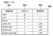
ここで、図6の管理テーブル600について説明する。管理テーブル600は、接続状態601と、0.5W以下602と、優先順位603との情報を紐付けて定義している。接続状態601には、接続状態にある各インタフェースの組み合わせが定義される。また、0.5W以下602には、接続状態601にあるインタフェースにおいて、0.5W以下を達成できるか否かの可否情報が定義される。例えば、図6においては、接続状態601がUSB又はLANの場合は、0.5W以下が可能であると定義されており、それ以外のインタフェースや組み合わせでは0.5W以下が達成できないことが定義されている。
Here, the management table 600 of FIG. 6 will be described. The management table 600 defines the
優先順位603には、複数のインタフェースが接続状態にある項目において、接続状態を優先させるインタフェースの情報が定義される。したがって、単独のインタフェースでは優先順位の情報は定義されない。図6を参照すると、例えば、接続状態601がUSB+LANの場合、即ち、USB(USB I/F部106)と、LAN(LAN I/F部107)とが接続状態にある場合には、優先順位603に指定されたLANの接続状態を優先的に維持することになる。
The
図4の説明に戻る。S406において、CPU101は、0.5Wを単独の接続で超えているか否かを判定し、単独の接続でも0.5Wを満足できない場合には、S410に進み、プリンタ2を電源オフに制御する。一方、複数の外部装置が接続状態にある場合で0.5Wを満足できない場合には、S407に進む。
Returning to the description of FIG. In S406, the
S407において、CPU101は、ROM102に格納された管理テーブル600を参照して、優先順位の確認を行う。なお、この管理テーブル600内の優先順位は、ユーザによって任意に設定することができる。ここでは、例えば、USB、LANが接続状態にある場合について説明する。
In step S <b> 407, the
USB、LANが接続状態にある場合、CPU101は、管理テーブルを参照して、優先順位603にLANが予め設定されているため、スリープに移行する際のインタフェースがLANに決定される。
When the USB and LAN are in the connected state, the
S408では、図6の管理テーブルを基に、LANでスリープした場合の消費電力が確認され、0.5W以下であるため、LANの単独接続に切り替えることを想定する。その場合、管理テーブル600の0.5W以下602には、LANが0.5W以下を達成することができると定義されているため、CPU101は、0.5W以下が可能であると判定し、S409に進む。ここで、管理テーブル600においてLANが0.5W以下を達成できないと定義されていれば、CPU101は、処理をS410に進めて、プリンタ2を電源オフに制御する。
In S408, based on the management table of FIG. 6, the power consumption when sleeping in the LAN is confirmed, and since it is 0.5 W or less, it is assumed that the LAN is switched to a single connection. In this case, since it is defined in the management table 600 that 0.5 W or less 602 indicates that the LAN can achieve 0.5 W or less, the
S409において、CPU101は、電源制御部104によって、LAN I/F部107以外のインタフェース部の電力供給を停止すると同時に、LAN I/F部107も必要最小限の電力供給に変更する。なお、上記S408の判定からS409に進んだ場合には、接続状態にあるUSB I/F部106への電源供給が停止されることになる。このように、本実施形態では、上記第1の実施形態とは異なり、複数の外部装置が接続状態にある場合であっても、予め定められた優先順位に従って、何れかの接続状態にあるインタフェースへの電源供給を停止する。また、エンジン制御部110に対しても電力の供給を止め、パネル制御部109においては、スリープからの復帰スイッチ以外の部分に対する電力供給を停止する。S411において、CPU101は、LAN I/F部107からのプリント命令や、パネルからの復帰スイッチからの命令を受信するまで、スリープ状態を維持し続け、復帰命令を受信したところで、S401の状態に戻る。
In step S <b> 409, the
以上説明したように、本実施形態に係る画像処理装置は、省電力制御を行う際に、現在の接続状態から管理テーブルに従って0.5W以下を達成できるか否かを判定する。さらに、本画像処理装置は、0.5W以下を達成できない場合であって、かつ、複数の外部装置が接続状態にある場合には、優先順位に従って何れかの外部装置への電源供給を停止することにより0.5W以下が達成できるか否かを判定する。これにより、本実施形態に係る画像処理装置は、より効果的に省電力制御を実行することができ、例えば、無駄に電源オフに制御することを低減し、再起動により、無駄な消費電力や待機時間を低減することができる。 As described above, when performing power saving control, the image processing apparatus according to the present embodiment determines whether 0.5 W or less can be achieved from the current connection state according to the management table. Furthermore, when the image processing apparatus cannot achieve 0.5 W or less and a plurality of external apparatuses are connected, power supply to any of the external apparatuses is stopped according to the priority order. It is determined whether 0.5 W or less can be achieved. Thereby, the image processing apparatus according to the present embodiment can execute power saving control more effectively.For example, it is possible to reduce useless power-off control, and useless power consumption or The waiting time can be reduced.
<その他の実施形態>
また、本発明は、以下の処理を実行することによっても実現される。即ち、上述した実施形態の機能を実現するソフトウェア(プログラム)を、ネットワーク又は各種記憶媒体を介してシステム或いは装置に供給し、そのシステム或いは装置のコンピュータ(又はCPUやMPU等)がプログラムを読み出して実行する処理である。
<Other embodiments>
The present invention can also be realized by executing the following processing. That is, software (program) that realizes the functions of the above-described embodiments is supplied to a system or apparatus via a network or various storage media, and a computer (or CPU, MPU, etc.) of the system or apparatus reads the program. It is a process to be executed.
Claims (9)
前記画像処理装置の電力状態を変化させる条件を満たした場合に、外部装置との通信が可能な接続状態にあるインタフェースを確認する確認手段と、
前記確認手段による確認結果に基づいて、前記画像処理装置がスリープ状態への移行が可能であるか否かを判定する判定手段と、
前記判定手段によって前記画像処理装置が所定の電力以下で動作するスリープ状態への移行が可能であると判定されると、該画像処理装置をスリープ状態へ移行させ、前記判定手段によって前記画像処理装置が所定の電力以下で動作するスリープ状態への移行が不可能であると判定されると、該画像処理装置を電源オフに制御する電源制御手段と
を備えることを特徴とする画像処理装置。 An image processing apparatus having a plurality of interfaces for connecting external devices,
Confirmation means for confirming an interface in a connected state capable of communicating with an external device when a condition for changing a power state of the image processing apparatus is satisfied;
Determination means for determining whether or not the image processing apparatus can enter a sleep state based on a confirmation result by the confirmation means;
When the determination unit determines that the image processing apparatus can shift to a sleep state in which the image processing apparatus operates at a predetermined power or less, the image processing apparatus shifts to the sleep state, and the determination unit causes the image processing apparatus to move to the sleep state. An image processing apparatus comprising: a power control unit configured to control the image processing apparatus to be turned off when it is determined that the image processing apparatus cannot be shifted to a sleep state that operates at a predetermined power or less.
前記確認手段によって確認された接続状態にあるインタフェースが複数存在するか否かを判定し、複数存在する場合は前記画像処理装置が所定の電力以下で動作するスリープ状態への移行が不可能であると判定することを特徴とする請求項1に記載の画像処理装置。 The determination means includes
It is determined whether or not there are a plurality of interfaces in the connection state confirmed by the confirmation unit. If there are a plurality of interfaces, it is impossible to shift to the sleep state in which the image processing apparatus operates at a predetermined power or less. The image processing apparatus according to claim 1, wherein:
前記判定手段は、
前記確認手段によって確認された接続状態にあるインタフェースが複数存在するか否かを判定し、接続状態にあるインタフェースが1つのみの場合は、前記記憶手段に記憶された当該インタフェースのスリープ状態における消費電力を参照し、前記所定の電力以下で動作することが可能な場合にはスリープ状態への移行が可能であると判定し、前記所定の電力以下で動作することが不可能な場合にはスリープ状態への移行が不可能であると判定することを特徴とする請求項1又は2に記載の画像処理装置。 Comprising storage means for storing power consumption in the sleep state in advance for each of the plurality of interfaces;
The determination means includes
It is determined whether or not there are a plurality of interfaces in the connection state confirmed by the confirmation unit, and when there is only one interface in the connection state, consumption of the interface stored in the storage unit in the sleep state When it is possible to operate with less than the predetermined power with reference to power, it is determined that the transition to the sleep state is possible, and when it is impossible to operate with less than the predetermined power, the sleep is performed. The image processing apparatus according to claim 1, wherein it is determined that transition to a state is impossible.
前記判定手段は、
前記確認手段によって確認された接続状態にあるインタフェースが、前記記憶手段において前記所定の電力以下での動作が可能であると定義されていればスリープ状態への移行が可能であると判定し、前記記憶手段において前記所定の電力以下での動作が不可能であると定義されていればスリープ状態への移行が不可能であると判定することを特徴とする請求項1に記載の画像処理装置。 The storage unit further stores in advance whether or not the operation at the predetermined power or less is possible in the sleep state for each combination of the interface in the connection state and the plurality of interfaces in the connection state. ,
The determination means includes
If the interface in the connection state confirmed by the confirmation unit is defined as being capable of operating at the predetermined power or less in the storage unit, it is determined that the transition to the sleep state is possible, The image processing apparatus according to claim 1, wherein if the storage unit is defined as being incapable of operating at the predetermined power or less, it is determined that the transition to the sleep state is impossible.
前記判定手段は、
前記確認手段によって確認された接続状態にあるインタフェースが、前記記憶手段において前記所定の電力以下での動作が不可能であると定義されてる場合に、前記接続状態にあるインタフェースが複数のインタフェースの組み合わせであるか否かを判定し、
単独のインタフェースであればスリープ状態への移行が不可能であると判定し、
複数のインタフェースの組み合わせであれば前記記憶手段の優先順位を参照し、優先的に接続状態を維持するように指定されたインタフェースが前記所定の電力以下での動作が可能であればスリープ状態への移行が可能であると判定し、優先的に接続状態を維持するように指定されたインタフェースが前記所定の電力以下での動作が不可能であればスリープ状態への移行が不可能であると判定することを特徴とする請求項4に記載の画像処理装置。 In the storage means, in the case of a combination of a plurality of interfaces for each combination of the interface in the connected state and the plurality of interfaces in the connected state, the priority order among the plurality of interfaces is stored in advance. And
The determination means includes
When the interface in the connection state confirmed by the confirmation unit is defined in the storage unit as being incapable of operating below the predetermined power, the interface in the connection state is a combination of a plurality of interfaces. Whether or not
If it is a single interface, it is determined that the transition to the sleep state is impossible,
If the interface is a combination of a plurality of interfaces, the priority order of the storage means is referred to, and if the interface designated to preferentially maintain the connection state can operate under the predetermined power, the sleep state is entered. It is determined that the transition is possible, and if the interface designated to preferentially maintain the connection state cannot operate under the predetermined power, it is determined that the transition to the sleep state is impossible. The image processing apparatus according to claim 4, wherein:
前記判定手段によって前記画像処理装置が所定の電力以下で動作するスリープ状態への移行が可能であると判定された場合に、接続状態にある前記複数のインタフェースのうち、前記優先的に接続状態を維持するように指定されていないインタフェースへの電源供給を停止することによって、該画像処理装置をスリープ状態へ移行させることを特徴とする請求項5に記載の画像処理装置。 The power control means includes
If the determination unit determines that the image processing apparatus can shift to a sleep state in which the image processing apparatus operates at a predetermined power or less, the connection state is preferentially selected from the plurality of interfaces in the connection state. 6. The image processing apparatus according to claim 5, wherein the image processing apparatus is shifted to a sleep state by stopping power supply to an interface not designated to be maintained.
確認手段が、前記画像処理装置の電力状態を変化させる条件を満たした場合に、外部装置との通信が可能な接続状態にあるインタフェースを確認する確認ステップと、
判定手段が、前記確認ステップによる確認結果に基づいて、前記画像処理装置がスリープ状態への移行が可能であるか否かを判定する判定ステップと、
電源制御手段が、前記判定ステップにおいて前記画像処理装置が所定の電力以下で動作するスリープ状態への移行が可能であると判定されると、該画像処理装置をスリープ状態へ移行させ、前記判定手段によって前記画像処理装置が所定の電力以下で動作するスリープ状態への移行が不可能であると判定されると、該画像処理装置を電源オフに制御する電源制御ステップと
を実行することを特徴とする画像処理装置の制御方法。 A method for controlling an image processing apparatus including a plurality of interfaces for connecting external devices,
A confirmation step for confirming an interface in a connection state capable of communication with an external device when the confirmation unit satisfies a condition for changing a power state of the image processing device;
A determination step for determining whether or not the image processing apparatus is capable of transitioning to a sleep state based on a confirmation result of the confirmation step;
When it is determined in the determining step that the image processing apparatus can shift to a sleep state in which the image processing apparatus operates at a predetermined power or less, the power control unit shifts the image processing apparatus to a sleep state, and the determination unit When the image processing apparatus determines that it is impossible to shift to a sleep state in which the image processing apparatus operates at a predetermined power or less, a power control step for controlling the image processing apparatus to be turned off is executed. For controlling an image processing apparatus.
前記外部装置との通信が可能な接続状態にあるインタフェースの種類又は数を確認する確認手段と、
前記画像処理装置の電力状態を変化させる条件を満たした場合に、前記確認手段による確認結果に基づいて、前記画像処理装置の電力状態を第1電力状態に移行させる否かを判定する判定手段と、
前記判定手段によって前記画像処理装置の電力状態を第1電力状態に移行させると判定した場合に、前記画像処理装置を第1電力状態に移行させ、前記判定手段によって前記画像処理装置の電力状態を第1電力状態に移行させないと判定した場合に、前記画像処理装置を第2電力状態に移行させる制御手段と
を備えることを特徴とする画像処理装置。 An image processing apparatus having an interface for connecting an external device,
Confirmation means for confirming the type or number of interfaces in a connected state capable of communication with the external device;
Determining means for determining whether or not to shift the power state of the image processing apparatus to the first power state based on a confirmation result by the confirmation means when a condition for changing the power state of the image processing apparatus is satisfied; ,
When the determination unit determines that the power state of the image processing apparatus is to be shifted to the first power state, the image processing apparatus is shifted to the first power state, and the determination unit is configured to change the power state of the image processing apparatus. An image processing apparatus comprising: control means for causing the image processing apparatus to shift to the second power state when it is determined not to shift to the first power state.
Priority Applications (2)
| Application Number | Priority Date | Filing Date | Title |
|---|---|---|---|
| JP2012031042A JP2013166311A (en) | 2012-02-15 | 2012-02-15 | Image processing apparatus, control method thereof, and program |
| US13/710,178 US8837973B2 (en) | 2012-02-15 | 2012-12-10 | Image processing apparatus, control method thereof, and storage medium |
Applications Claiming Priority (1)
| Application Number | Priority Date | Filing Date | Title |
|---|---|---|---|
| JP2012031042A JP2013166311A (en) | 2012-02-15 | 2012-02-15 | Image processing apparatus, control method thereof, and program |
Publications (1)
| Publication Number | Publication Date |
|---|---|
| JP2013166311A true JP2013166311A (en) | 2013-08-29 |
Family
ID=48945650
Family Applications (1)
| Application Number | Title | Priority Date | Filing Date |
|---|---|---|---|
| JP2012031042A Pending JP2013166311A (en) | 2012-02-15 | 2012-02-15 | Image processing apparatus, control method thereof, and program |
Country Status (2)
| Country | Link |
|---|---|
| US (1) | US8837973B2 (en) |
| JP (1) | JP2013166311A (en) |
Cited By (1)
| Publication number | Priority date | Publication date | Assignee | Title |
|---|---|---|---|---|
| JP2016030434A (en) * | 2014-07-30 | 2016-03-07 | 株式会社沖データ | Image forming apparatus |
Families Citing this family (5)
| Publication number | Priority date | Publication date | Assignee | Title |
|---|---|---|---|---|
| JP6381325B2 (en) * | 2014-07-11 | 2018-08-29 | キヤノン株式会社 | Printing system comprising a printing device and a printing control device |
| US9830113B2 (en) | 2016-04-19 | 2017-11-28 | Funai Electric Co., Ltd | Imaging system controller coordination |
| JP6786358B2 (en) * | 2016-11-08 | 2020-11-18 | キヤノン株式会社 | Information processing device and control method of information processing device |
| JP7242223B2 (en) * | 2018-09-06 | 2023-03-20 | キヤノン株式会社 | Image forming system, image forming apparatus |
| US20260109166A1 (en) * | 2024-10-22 | 2026-04-23 | Canon Kabushiki Kaisha | Image printing apparatus, control method of image printing apparatus, and storage medium |
Family Cites Families (3)
| Publication number | Priority date | Publication date | Assignee | Title |
|---|---|---|---|---|
| JP3984876B2 (en) * | 2002-07-03 | 2007-10-03 | キヤノン株式会社 | Image forming apparatus and power control method |
| US6895196B2 (en) * | 2002-10-08 | 2005-05-17 | Canon Kabushiki Kaisha | Image forming apparatus having reduced power consumption mode and control method therefor |
| JP2008142942A (en) | 2006-12-07 | 2008-06-26 | Canon Inc | Printer power management control device, printer power management control method, and printer control program |
-
2012
- 2012-02-15 JP JP2012031042A patent/JP2013166311A/en active Pending
- 2012-12-10 US US13/710,178 patent/US8837973B2/en not_active Expired - Fee Related
Cited By (1)
| Publication number | Priority date | Publication date | Assignee | Title |
|---|---|---|---|---|
| JP2016030434A (en) * | 2014-07-30 | 2016-03-07 | 株式会社沖データ | Image forming apparatus |
Also Published As
| Publication number | Publication date |
|---|---|
| US8837973B2 (en) | 2014-09-16 |
| US20130209132A1 (en) | 2013-08-15 |
Similar Documents
| Publication | Publication Date | Title |
|---|---|---|
| JP4459150B2 (en) | Printing apparatus and control method thereof | |
| JP2013166311A (en) | Image processing apparatus, control method thereof, and program | |
| JP5852320B2 (en) | Image forming apparatus and control method thereof | |
| JP2012142821A (en) | Controller, image formation device, control method, and control program | |
| CN103516940A (en) | Information processing apparatus and control method therefor | |
| JP6127682B2 (en) | Processing control device, image processing device | |
| JP2012224079A (en) | Printing apparatus | |
| JP6489751B2 (en) | Data processing apparatus, control method therefor, and program | |
| US20180224795A1 (en) | Printing system including printing apparatus and printing control apparatus | |
| JP5874459B2 (en) | Image forming apparatus, image forming method, and program | |
| JP6137849B2 (en) | Information processing apparatus and information processing apparatus control method | |
| JP2014079991A (en) | Electronic apparatus and control method thereof, and program | |
| JP6007657B2 (en) | Image forming system and image forming apparatus | |
| JP2010130163A (en) | Image forming device, control device, and program | |
| US9152359B2 (en) | Image forming apparatus that selects appropriate power saving mode for each time slot | |
| JP2010111105A (en) | Image forming apparatus, method for controlling image forming apparatus, program and computer-readable recording medium | |
| US20120084585A1 (en) | Information processing apparatus capable of remote power control, power control method therefor, and storage medium | |
| JP5673299B2 (en) | Print control apparatus, image forming apparatus, and print system | |
| JP5742274B2 (en) | Image forming apparatus, image forming control method, image forming control program, and recording medium | |
| JP6225416B2 (en) | COMMUNICATION SYSTEM, COMMUNICATION DEVICE, AND COMMUNICATION METHOD | |
| JP2011065548A (en) | Apparatus, program and system for forming image | |
| JP2005115478A (en) | Control system | |
| JP2015116685A (en) | Image forming apparatus, image forming apparatus control method, and program | |
| JP2014104654A (en) | Image forming apparatus and control method of the same | |
| JP2010056659A (en) | Image forming apparatus, controller, and program |