JP2010056659A - Image forming apparatus, controller, and program - Google Patents
Image forming apparatus, controller, and program Download PDFInfo
- Publication number
- JP2010056659A JP2010056659A JP2008217001A JP2008217001A JP2010056659A JP 2010056659 A JP2010056659 A JP 2010056659A JP 2008217001 A JP2008217001 A JP 2008217001A JP 2008217001 A JP2008217001 A JP 2008217001A JP 2010056659 A JP2010056659 A JP 2010056659A
- Authority
- JP
- Japan
- Prior art keywords
- unit
- image forming
- control
- power supply
- control unit
- Prior art date
- Legal status (The legal status is an assumption and is not a legal conclusion. Google has not performed a legal analysis and makes no representation as to the accuracy of the status listed.)
- Pending
Links
Images


Classifications
-
- Y—GENERAL TAGGING OF NEW TECHNOLOGICAL DEVELOPMENTS; GENERAL TAGGING OF CROSS-SECTIONAL TECHNOLOGIES SPANNING OVER SEVERAL SECTIONS OF THE IPC; TECHNICAL SUBJECTS COVERED BY FORMER USPC CROSS-REFERENCE ART COLLECTIONS [XRACs] AND DIGESTS
- Y02—TECHNOLOGIES OR APPLICATIONS FOR MITIGATION OR ADAPTATION AGAINST CLIMATE CHANGE
- Y02D—CLIMATE CHANGE MITIGATION TECHNOLOGIES IN INFORMATION AND COMMUNICATION TECHNOLOGIES [ICT], I.E. INFORMATION AND COMMUNICATION TECHNOLOGIES AIMING AT THE REDUCTION OF THEIR OWN ENERGY USE
- Y02D10/00—Energy efficient computing, e.g. low power processors, power management or thermal management
Abstract
Description
本発明は、画像形成装置、制御装置、およびプログラムに関する。 The present invention relates to an image forming apparatus, a control apparatus, and a program.
プリンタや複写機、ファクシミリ等の画像形成装置では、例えばネットワーク等の通信回線や電話回線などを介して接続された端末装置、専用線で接続された画像読取装置等から画像データ等を受け取り、印刷処理を行う。また、これらの画像形成装置では、例えば、予め定めた時間以上に亘って画像データ等の入力がない場合などにて、一般に、消費電力を低く抑える所謂省電力状態に移行するように制御されることが多い。
特許文献1には、ジョブ実行に応じた電源制御を行なうために、実行しようとするジョブが特定された時点で、ジョブ実行に必要なユニットに対して電源供給を行なうとともに、ユニットの起動を指示するようにして、必要な時のみに電源の電力を消費するようにした技術が開示されている。これにより、画像形成装置が消費する電力を必要最小限としている。
In image forming apparatuses such as printers, copiers, and facsimiles, for example, image data is received from a terminal device connected via a communication line such as a network or a telephone line, an image reading device connected via a dedicated line, and printed. Process. Further, in these image forming apparatuses, for example, when there is no input of image data or the like for a predetermined time or more, generally, control is performed so as to shift to a so-called power saving state in which power consumption is kept low. There are many cases.
In Patent Document 1, in order to perform power control in accordance with job execution, when a job to be executed is specified, power is supplied to a unit necessary for job execution and an instruction to start the unit is given. Thus, a technique is disclosed in which power of the power source is consumed only when necessary. This minimizes the power consumed by the image forming apparatus.
ここで一般の画像形成装置では、処理に必要な制御ユニットへの電源供給、および不必要な制御ユニットへの電源供給の停止は、画像形成装置全体を制御する起動制御手段(SCU:System Control Unit)によって行なわれる。例えば、起動制御手段(SCU)は、次に実行するジョブに必要となる制御ユニットを判断し、電源供給が必要な制御ユニットに電源を供給する制御を行なう。 Here, in a general image forming apparatus, power supply to a control unit necessary for processing and power supply to an unnecessary control unit are stopped by a start control unit (SCU: System Control Unit) that controls the entire image forming apparatus. ). For example, the activation control means (SCU) determines a control unit necessary for a job to be executed next, and performs control to supply power to a control unit that requires power supply.
しかしながら、かかる場合に、各制御ユニットの電源供給・停止についての状況を、ジョブ種類毎に予め起動制御手段(SCU)で把握しておく必要がある。そのためには、例えば、節電の移行条件が異なる制御ユニット毎に起動制御手段(SCU)の制御プログラムの変更が余儀なくされる。また、制御ユニット構成などに一部、変更があった場合には、同様に起動制御手段(SCU)の制御プログラムを変更する必要があった。 However, in such a case, it is necessary to grasp the status of power supply / stop of each control unit in advance by the start control means (SCU) for each job type. For this purpose, for example, the control program of the activation control means (SCU) must be changed for each control unit having different power saving transition conditions. In addition, when there is a partial change in the control unit configuration or the like, it is necessary to similarly change the control program of the activation control means (SCU).
本発明は、各制御ユニットまたはデバイスの判断で電源モードを遷移し、各制御ユニットまたはデバイスの機能に応じた節電状態を維持することを目的とする。 It is an object of the present invention to change the power mode according to the judgment of each control unit or device and maintain a power saving state corresponding to the function of each control unit or device.
請求項1に記載の発明は、電源供給・停止を制御可能な一単位であって画像情報に基づき画像形成を行う画像形成機能部と、電源供給・停止を制御可能な一単位であって前記画像形成機能部との間で画像形成に関連する情報または信号の送受信を行う複数の制御機能部と、前記画像形成機能部および複数の前記制御機能部の各々に電力を供給する電力供給手段と、前記画像形成機能部および複数の前記制御機能部を各々接続する機内通信手段とを備え、前記画像形成機能部および複数の前記制御機能部の各々は、前記機内通信手段を介して得られる情報から自身の電源供給・停止状態を自ら判断し、前記電力供給手段からの電源供給・停止の制御を自ら実施することを特徴とする画像形成装置である。 The invention according to claim 1 is a unit capable of controlling power supply / stop, and is an image forming function unit that forms an image based on image information, and is a unit capable of controlling power supply / stop. A plurality of control function units that transmit / receive information or signals related to image formation to / from the image forming function unit; and a power supply unit that supplies power to each of the image forming function unit and the plurality of control function units And an in-machine communication means for connecting each of the image forming function section and the plurality of control function sections, and each of the image forming function section and the plurality of control function sections is information obtained via the in-machine communication means. The image forming apparatus is characterized in that its own power supply / stop state is determined by itself and control of power supply / stop from the power supply means is performed by itself.
請求項2に記載の発明は、前記画像形成機能部は、自らを個別に制御する画像形成制御手段を備え、複数の前記制御機能部は、自らを個別に制御する複数の機能部制御手段を各々備えたことを特徴とする請求項1記載の画像形成装置である。
請求項3に記載の発明は、起動時にて、前記画像形成機能部および複数の前記制御機能部にて初期化処理が必要な機能部では、自ら初期化処理を実行し、当該初期化処理後に前記電力供給手段からの前記電源供給・停止状態の遷移を自らの判断で実行することを特徴とする請求項1または2記載の画像形成装置である。
請求項4に記載の発明は、前記電源供給・停止状態は、システム・スリープ時の電源オフ状態、スタンバイ状態、ジョブ実行状態、を含むことを特徴とする請求項1記載の画像形成装置である。
請求項5に記載の発明は、ジョブ実行の開始時にて、前記機内通信手段を介して前記画像形成機能部および複数の前記制御機能部にジョブ実行の開始が通知され、当該ジョブ実行に関連しない何れかの機能部では当該通知の前の電源供給・停止の状態が維持されることを特徴とする請求項1乃至4何れかに記載の画像形成装置である。
請求項6に記載の発明は、前記画像形成機能部と複数の前記制御機能部とを統合的に制御する統合制御手段を更に備えたことを特徴とする請求項1乃至5何れかに記載の画像形成装置である。
According to a second aspect of the present invention, the image forming function unit includes an image formation control unit that individually controls itself, and the plurality of control function units include a plurality of function unit control units that individually control the image forming function unit. The image forming apparatus according to claim 1, wherein each of the image forming apparatuses is provided.
According to a third aspect of the present invention, at the time of start-up, the image forming function unit and the function units that require initialization processing in the plurality of control function units execute initialization processing themselves, and after the initialization processing The image forming apparatus according to claim 1, wherein the power supply unit performs the transition of the power supply / stop state based on its own judgment.
According to a fourth aspect of the present invention, in the image forming apparatus according to the first aspect, the power supply / stop state includes a power-off state during system sleep, a standby state, and a job execution state. .
According to the fifth aspect of the present invention, at the start of job execution, the image forming function unit and the plurality of control function units are notified of the start of job execution via the in-flight communication unit, and are not related to the job execution. 5. The image forming apparatus according to claim 1, wherein the power supply / stop state before the notification is maintained in any one of the functional units.
The invention described in claim 6 further comprises an integrated control means for integrally controlling the image forming function section and the plurality of control function sections. An image forming apparatus.
請求項7に記載の発明は、電源供給・停止を制御可能な一単位であって画像情報に基づき画像形成を行う画像形成機能部、および/または電源供給・停止を制御可能な一単位であって当該画像形成機能部との間で画像形成に関連する情報または信号の送受信を行う複数の制御機能部から機内通信手段を介して送信される情報を取得する情報取得手段と、前記画像形成機能部および複数の前記制御機能部の各々に対応して個別に設けられ、前記情報取得手段にて取得した前記情報から当該画像形成機能部および複数の当該制御機能部各々の電源供給・停止状態を判断し、当該画像形成機能部および複数の当該制御機能部各々への電源供給・停止を個別に制御する制御手段とを備えたことを特徴とする制御装置である。
請求項8に記載の発明は、前記制御手段は、起動時にて、前記画像形成機能部および複数の前記制御機能部にて初期化処理が必要な機能部では初期化処理を実行し、当該初期化処理後に前記電源供給・停止状態の遷移を自らの判断で実行することを特徴とする請求項7記載の制御装置である。
請求項9に記載の発明は、前記制御手段は、ジョブ実行の開始時にて、前記機内通信手段を介して前記画像形成機能部および複数の前記制御機能部にジョブ実行の開始が通知された場合に、当該ジョブ実行に関連しない何れかの機能部では当該通知の前の電源供給・停止の状態を維持することを特徴とする請求項7または8記載の制御装置である。
The invention described in
According to an eighth aspect of the present invention, the control unit executes an initialization process in the image forming function unit and a function unit that requires an initialization process in the plurality of control function units at the time of activation, and The control device according to
According to a ninth aspect of the invention, when the job execution is started, the control unit is notified of the start of job execution to the image forming function unit and the plurality of control function units via the in-machine communication unit. The control device according to
請求項10に記載の発明は、コンピュータに、電源供給・停止を制御可能な一単位であって画像情報に基づき画像形成を行う画像形成機能部、および/または電源供給・停止を制御可能な一単位であって当該画像形成機能部との間で画像形成に関連する情報または信号の送受信を行う複数の制御機能部から機内通信手段を介して送信される情報を取得する機能と、前記画像形成機能部および複数の前記制御機能部の各々に対応して個別に設けられ、前記機内通信手段を介して取得した前記情報から当該画像形成機能部および複数の当該制御機能部各々の電源供給・停止状態を判断し、当該画像形成機能部および複数の当該制御機能部各々への電源供給・停止を個別に制御する機能とを実現するプログラムである。
請求項11に記載の発明は、前記制御する機能は、起動時にて、前記画像形成機能部および複数の前記制御機能部にて初期化処理が必要な機能部では初期化処理を実行し、当該初期化処理後に前記電源供給・停止状態の遷移を自らの判断で実行することを特徴とする請求項10記載のプログラムである。
請求項12に記載の発明は、前記制御する機能は、ジョブ実行の開始時にて、前記機内通信手段を介して前記画像形成機能部および複数の前記制御機能部にジョブ実行の開始が通知された場合に、当該ジョブ実行に関連しない何れかの機能部では当該通知の前の電源供給・停止の状態を維持することを特徴とする請求項10または11記載のプログラムである。
According to the tenth aspect of the present invention, an image forming function unit that performs image formation based on image information and / or one that can control power supply / stop can be controlled by a computer. A function of acquiring information transmitted via in-machine communication means from a plurality of control function units that transmit and receive information or signals related to image formation to and from the image forming function unit; Power supply / stop of each of the image forming function unit and the plurality of control function units individually provided corresponding to each of the function unit and the plurality of control function units, from the information acquired via the in-flight communication unit This is a program for determining a state and realizing a function of individually controlling power supply / stop to each of the image forming function unit and the plurality of control function units.
According to an eleventh aspect of the present invention, the function to be controlled is an initialization process performed by the image forming function unit and a function unit that requires an initialization process in the plurality of control function units at the time of activation. The program according to claim 10, wherein the transition of the power supply / stop state is executed by own judgment after the initialization process.
According to a twelfth aspect of the invention, the function to be controlled is notified of the start of job execution to the image forming function unit and the plurality of control function units via the in-flight communication unit at the start of job execution. In this case, the program according to
本発明の請求項1によれば、各制御ユニットまたはデバイスの判断で電源モードを遷移し、本発明を採用しない場合に比べて、各制御ユニットまたはデバイスの機能に応じた節電状態を維持することができる。
本発明の請求項2によれば、本発明を採用しない場合に比べて、各制御ユニットまたは各デバイス毎の機能に応じた節電状態を設定することができる。
本発明の請求項3によれば、本発明を採用しない場合に比べて、初期化処理を実行する際に各制御ユニットまたはデバイスの機能に応じた節電状態を維持することができる。
本発明の請求項4によれば、各制御ユニットまたは各デバイス毎に個別の電源供給・停止状態を設定し、本発明を採用しない場合に比べて、画像形成装置全体としての電力消費を抑制することができる。
本発明の請求項5によれば、本発明を採用しない場合に比べて、ジョブ実行に関連しない機能部での電力消費を抑制することができる。
本発明の請求項6によれば、本発明を採用しない場合に比べて、画像形成装置全体としての電源供給・停止状態を監視し、本発明を採用しない場合に比べて、各制御ユニットまたはデバイスの機能に応じた節電状態をより効果的に維持することができる。
According to claim 1 of the present invention, the power supply mode is changed by the judgment of each control unit or device, and the power saving state corresponding to the function of each control unit or device is maintained as compared with the case where the present invention is not adopted. Can do.
According to the second aspect of the present invention, it is possible to set the power saving state corresponding to the function of each control unit or each device as compared with the case where the present invention is not adopted.
According to the third aspect of the present invention, it is possible to maintain a power saving state corresponding to the function of each control unit or device when executing the initialization process, as compared with the case where the present invention is not adopted.
According to
According to the fifth aspect of the present invention, it is possible to suppress power consumption in a functional unit not related to job execution, compared to a case where the present invention is not adopted.
According to the sixth aspect of the present invention, the power supply / stop state of the entire image forming apparatus is monitored as compared with the case where the present invention is not adopted, and each control unit or device is compared with the case where the present invention is not adopted. The power-saving state according to the function of can be maintained more effectively.
本発明の請求項7によれば、各制御ユニットまたはデバイスの判断で電源モードを遷移し、本発明を採用しない場合に比べて、各制御ユニットまたはデバイスの機能に応じた節電状態を維持することができる。
本発明の請求項8によれば、本発明を採用しない場合に比べて、初期化処理を実行する際に各制御ユニットまたはデバイスの機能に応じた節電状態を維持することができる。
本発明の請求項9によれば、本発明を採用しない場合に比べて、ジョブ実行に関連しない機能部での電力消費を抑制することができる。
According to
According to
According to the ninth aspect of the present invention, it is possible to suppress power consumption in a functional unit not related to job execution, compared to a case where the present invention is not adopted.
本発明の請求項10によれば、各制御ユニットまたはデバイスの判断で電源モードを遷移し、本発明を採用しない場合に比べて、各制御ユニットまたはデバイスの機能に応じた節電状態を維持することができる。
本発明の請求項11によれば、本発明を採用しない場合に比べて、初期化処理を実行する際に各制御ユニットまたはデバイスの機能に応じた節電状態を維持することができる。
本発明の請求項12によれば、本発明を採用しない場合に比べて、ジョブ実行に関連しない機能部での電力消費を抑制することができる。
According to the tenth aspect of the present invention, the power mode is changed by the judgment of each control unit or device, and the power saving state corresponding to the function of each control unit or device is maintained as compared with the case where the present invention is not adopted. Can do.
According to the eleventh aspect of the present invention, it is possible to maintain a power saving state corresponding to the function of each control unit or device when executing the initialization process, as compared with the case where the present invention is not adopted.
According to the twelfth aspect of the present invention, compared with a case where the present invention is not adopted, it is possible to suppress power consumption in a functional unit not related to job execution.
以下、添付図面を参照して、本発明の実施の形態について詳細に説明する。
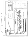
図1は本実施の形態が適用される画像形成装置1の全体構成の一例を示した図である。図1に示す画像形成装置1は、各色の画像データ(画像情報)に基づき画像形成を行う画像形成機能部の一例としての画像形成ユニット2、原稿上の画像を読み取って画像データを生成し画像形成ユニット2に送る制御機能部の一例としての画像読取ユニット3を備えている。また、ユーザからの操作入力の受付やユーザに対する各種情報の表示を行う制御機能部の一例としてのユーザインターフェース(UI)ユニット4、例えば公衆電話回線を介して画像情報の送受信を行なう制御機能部の一例としてのファクシミリ(FAX)ユニット5を備えている。更に、画像形成ユニット2の筐体内部、または画像形成ユニット2に外付けで設けられ、画像形成ユニット2に用紙を供給する制御機能部の一例としてのトレイ(Tray)ユニット6、例えばハードディスクドライブ(HDD)やフラッシュメモリ等で構成される外部記憶装置である制御機能部の一例としてのメモリユニット6を備えている。また更に、画像形成装置1全体の動作や通信回線を介した通信等を制御する統合制御手段の一例としてのシステム制御(System Cont.)ユニット8、各部に電力を供給する電力供給手段の一例としての電力供給ユニット9を備えている。
Embodiments of the present invention will be described below in detail with reference to the accompanying drawings.
FIG. 1 is a diagram illustrating an example of the overall configuration of an image forming apparatus 1 to which the exemplary embodiment is applied. An image forming apparatus 1 shown in FIG. 1 generates an image data by reading an image on an original, an
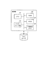
図2は、図1に示す画像形成装置1の機能構成を説明するための図である。本実施の形態では、画像形成機能部である画像形成ユニット2、および制御機能部である画像読取ユニット3、UIユニット4、FAXユニット5、トレイユニット6、メモリユニット7、システム制御ユニット8が、機内通信手段の一例である機内LAN10に接続されている。本実施の形態では、各制御機能部、画像形成機能部で構成されるユニット間を1本のバス(機内LAN10)に接続し、ユニット間の通信を実現している。この点において、各ユニット間の通信を異なる制御バスによって接続していた従来の技術とは異なる。
また、本実施の形態では、外部の機器(外部機器)とは、システム制御ユニット8を介して外部LAN12によって接続されている。
FIG. 2 is a diagram for explaining a functional configuration of the image forming apparatus 1 shown in FIG. In the present embodiment, an
In the present embodiment, an external device (external device) is connected to the
各ユニットには、後述するような電源供給・停止状態の判断や電源供給・停止の制御を各々、実行するための制御部(CPU)が設けられている。この制御部(CPU)として、図2に示すように、画像形成ユニット2には画像形成制御手段(制御手段)の一例としての画像形成制御部92、画像読取ユニット3には機能部制御手段(制御手段)の一例としての画像読取制御部93、UIユニット4には機能部制御手段(制御手段)の一例としてのUI制御部94、FAXユニット5には機能部制御手段(制御手段)の一例としてのFAX制御部95、トレイユニット6には機能部制御手段の一例としてのトレイ制御部96、メモリユニット7には機能部制御手段(制御手段)の一例としてのメモリ制御部97、システム制御ユニット8には機能部制御手段(制御手段)の一例としてのシステム制御ユニット制御部98が設けられている。
Each unit is provided with a control unit (CPU) for executing power supply / stop state determination and power supply / stop control, which will be described later. As the control unit (CPU), as shown in FIG. 2, the
また、画像形成装置1の画像形成ユニット2および他のユニット(画像読取ユニット3、UIユニット4、FAXユニット5、トレイユニット6、メモリユニット7、システム制御ユニット8)には電力ライン11が接続されており、この電力ライン11に接続されている電力供給ユニット9を介して電力が供給される。電力供給ユニット11は、常夜電源として、予め定めた電圧(24V)の電力を常に供給する。
In addition, a
画像形成機能部である画像形成ユニット2、各種制御機能部である画像読取ユニット3、UIユニット4、FAXユニット5、トレイユニット6、メモリユニット7、システム制御ユニット8は、電源モードの制御が可能な単位である。例えば、
(i)システム・スリープ時の電源オフ(OFF)、
(ii)スタンバイ時の電力5V、
(iii)ジョブ実行時の電力24V
などの電源モードを持って制御する。これら電源モードの制御では、画像形成機能部、各種制御機能部自身がシステム状態、もしくは、予め定めた時間経過を判断して、電源モードを遷移させる。即ち、画像形成ユニット2の画像形成制御部92、各種制御機能部(画像読取ユニット3、UIユニット4、FAXユニット5、トレイユニット6、メモリユニット7、システム制御ユニット8)の制御部(画像読取制御部93、UI制御部94、FAX制御部95、トレイ制御部96、メモリ制御部97、システム制御ユニット制御部98)は、機内通信手段(機内LAN10)を介して得られる情報から自身の電源供給・停止状態を自ら判断し、電力供給手段である電力供給ユニット9からの電源供給・停止の制御を自ら実施している。従って、画像形成制御部92および制御部(画像読取制御部93、UI制御部94、FAX制御部95、トレイ制御部96、メモリ制御部97、システム制御ユニット制御部98)は、機内通信手段(機内LAN10)を介して送信される情報を取得する情報取得手段としても機能する。
The
(I) Power off during system sleep (OFF),
(Ii)
(Iii) Electric power at the time of
Control with a power mode. In control of these power modes, the image forming function unit and the various control function units themselves determine the system state or the passage of a predetermined time, and change the power mode. That is, the image forming
尚、このような電源供給・停止の制御は、各ユニットの間で行なわれる他、この各ユニットを構成するユニット内の各デバイス(各構成要素)の間においても実行される。即ち、各ユニットを構成する各デバイスは、各デバイス間を接続するユニット内LAN(後述)に各々、接続されている。そして、各デバイスに設けられた制御部によって、自身の電源供給・停止状態を自ら判断し、電源供給・停止の制御を自ら実施するように構成することが可能である。 Such power supply / stop control is performed between the units, and is also performed between devices (components) in the units constituting the units. That is, each device constituting each unit is connected to an intra-unit LAN (described later) that connects each device. Then, the control unit provided in each device can determine the power supply / stop state of itself and control the power supply / stop by itself.
〔各ユニット内の説明〕
各ユニット内で行なわれる電源供給・停止の制御について、画像形成ユニット2を代表例として説明する。
図3は、画像形成ユニット2の機能構成を説明する図である。画像形成機能部である画像形成ユニット2は、各色の画像データに基づき画像形成処理を行なっている。図3に示す画像形成ユニット2は、ユニット内LAN21に、各デバイスの制御部として各種制御部22が接続されている。この各種制御部22としては、電子写真方式の画像形成処理を制御する帯電制御部、露光制御部、現像制御部、転写制御部、定着制御部などがある。これらの各種制御部22は、機構部23の各種機構(デバイス)を制御する。より具体的には、各種制御部22は、メカトロニクスI/O(IN/OUT)を介して、機構部23に配置されたモータやソレノイド、クラッチなどのデバイスの動作を制御している。また、機構部23に配置された感光体ドラムを帯電する際の帯電器や、感光体ドラムを露光するレーザ露光器などのデバイスに供給するプロセス設定値を制御している。
[Description in each unit]
The power supply / stop control performed in each unit will be described using the
FIG. 3 is a diagram illustrating a functional configuration of the
また、ユニット内LAN21には、画像形成制御部92が接続されている。画像形成制御部92は、画像形成制御部92を制御するCPU921と、機内LAN10に接続され、機内LAN10から得られるコマンドにフィルタリングをかけるコマンドフィルタ922とを有している。例えば機内LAN10にて、画像形成ユニット2が処理すべき内容であることを示すコマンドが付された情報がブロードキャストされた際に、コマンドフィルタ922にてこのコマンドを選別する。電力供給ユニット9から電力ライン11を介して提供される常夜電源(例えば5V)は、このLANコマンドを検知するコマンドフィルタ922だけに供給されるように構成すれば、待機状態にてCPU921をオフすることもでき、更なる省電力化が図られる。
In addition, an image
また、画像形成ユニット2などの各ユニットには、そのユニット内の電源部を有している。図3に示す画像形成ユニット2には画像形成電源部25が設けられており、画像形成制御部92の制御下で動作する。更に、各ユニットには、ユニット内の電源部から各制御部に電力が供給されており、図3に示す画像形成ユニット2には、この画像形成電源部25からのスタンバイ電力(5V)を各種制御部22に提供する制御用電力ライン26が設けられている。また、画像形成ユニット2には、画像形成電源部25からの稼働電力(24V)を機構部23に提供する稼働電力ライン27が設けられている。
Each unit such as the
〔電源モード遷移の動作説明〕
次に、画像形成機能部および制御機能部、統合制御機能部の動作について説明する。
図4〜図6では、3つの異なるモードについて、画像形成ユニット2、画像読取ユニット3、FAXユニット5、UIユニット4、およびシステム制御ユニット8の電源モード遷移の状態を説明している。各ユニットでは、各ユニットの個別の判断で電源モードを遷移し、各ユニットの機能に応じた節電状態を維持する。この例では、画像形成ユニット2、画像読取ユニット3、FAXユニット5が自らの判断で遷移する状態として、電源オフ状態、5Vのオン状態、24Vのオン状態の3状態が示されている。また、UIユニット4が自らの判断で遷移する状態として、電源オフ状態、LEDのオフ状態、24Vのオン状態の3状態が示されている。更に、システム制御ユニット8の電源遷移状態として、電源オフ状態、CPUオフ状態、5Vのオン状態、24Vのオン状態の4状態が示されている。
[Description of power mode transition]
Next, operations of the image forming function unit, the control function unit, and the integrated control function unit will be described.
4 to 6 illustrate the power mode transition states of the
〔ファクシミリ受信があった場合の電源モード遷移〕
まず、図4は、ファクシミリ受信があった場合の電源モード遷移の状態を示した図である。
図に示す「電源オン(ON)」は、例えば画像形成装置1の全体のスイッチ(メインスイッチ)がオフからオンされた状態であり、各ユニットは電源オンにより初期化処理を開始する。
[Power mode transition when there is facsimile reception]
First, FIG. 4 is a diagram showing a state of power supply mode transition when there is facsimile reception.
“Power on (ON)” shown in the drawing is a state in which, for example, the entire switch (main switch) of the image forming apparatus 1 is turned on, and each unit starts an initialization process when the power is turned on.
図に示す「レディ(Ready)」状態は、システム全体として、プリントや複写、ファクシミリ、スキャナ等の各種の画像処理動作が実行可能な状態であり、各ユニットの初期化処理が終了した状態である。画像形成ユニット2、画像読取ユニット3、FAXユニット5、UIユニット4の各ユニットは、各々が初期化処理を行ない、初期化処理の終了後、機内LAN10を介して、初期化処理を終了してレディ状態になったことを示すコマンドをブロードキャストする。システム制御ユニット8は、各ユニットがレディ状態となったことを認識し、必要に応じて、例えば外部機器に対して「画像形成装置1がレディ状態にある」旨の情報を提供する。尚、「レディ状態」では、初期化が完了した時点で、直ぐに稼働することが必要ではないユニットは、自らの判断で電源レベルを低いレベルに落とし、節電を行なう。その後に稼働の必要のないユニットにおいては、自ら積極的に非稼働とすることで、良好な節電状態を維持する。
尚、「ブロードキャスト」とは、機内LAN10を介して機内LAN10に接続されたすべてのユニットにコマンドが付された情報を送信することをいう。
The “Ready” state shown in the figure is a state in which various image processing operations such as printing, copying, facsimile, and scanner can be executed as a whole system, and the initialization process of each unit has been completed. . Each of the
Note that “broadcast” refers to transmitting information with a command to all units connected to the in-machine LAN 10 via the in-machine LAN 10.
図の「節電モード」は、ユーザから認識できる節電状態として、レディ状態になった後に例えば予め定めた時間を経過しても画像情報の入力がない場合に、UIユニット4およびシステム制御ユニット8が節電モードに移行した状態である。UIユニット4のパネルの照明も消えて(LEDオフ(OFF)状態)、システム制御ユニット8のシステム制御ユニット制御部98がオフしている状態(CPUオフ(OFF)状態)である。ただし、システム制御ユニット8では、外部LAN12を介した外部機器からの印刷ジョブデータの受信やUIユニット4でのユーザからの操作入力などを監視する機能部(ASIC)が節電モードにおいてもオンされている。そして、ASICは、印刷ジョブデータの受信やユーザからの操作入力などがあった場合に、システム制御ユニット制御部98をCPUオフ状態から5Vのオン状態に移行させる。
尚、システム制御ユニット8以外の他の各ユニットの電源オフ(OFF)状態は、外部の割込によって起動することが可能である状態である。
The “power saving mode” in the figure is a power saving state that can be recognized by the user. For example, when there is no input of image information after a predetermined time has passed after the ready state, the
The power off (OFF) state of each unit other than the
図2および図4を参照しながら更に詳述する。
まず、電力供給ユニット9から電力ライン11を介して電源がオンされ、画像形成装置1がシステム起動されると、初期化処理が必要なユニットは、自身が初期化するのにユニットの機能に応じた電源モードにより初期化処理を行なう。このとき、例えば、初期化処理を行なうに際して各ユニット相互を同期させることが必要となる場合には、各ユニットから必要なステータスを取得するために、システム制御ユニット8は各ユニットとの間の通信を行う。しかし、基本的には、本実施の形態の各ユニットは独立して初期化処理を行う。そのため、電源がオンされると、画像形成ユニット2、画像読取ユニット3、UIユニット4、FAXユニット5、およびシステム制御ユニット8は、電源オフの状態から、24V電源オンの状態へ遷移する。図4には示していないが、トレイユニット6、メモリユニット7も同様である。そして、この電源状態にて、各ユニットは、初期化処理を実行する。より具体的には、各ユニットは、フルパワーで初期化処理を実行し、初期化処理に必要な時間の経過後に初期化処理を完了する行為と、初期化処理の完了後の予め定めた時間の経過後に電源レベルをフルパワー状態よりも低いレベルに落としたモードに移行する行為とを各ユニット自らの判断により行なう。
Further details will be described with reference to FIGS.
First, when the
すなわち、画像形成ユニット2の画像形成制御部92は、自らの判断により、自らの基準に基づき、初期化処理中に24Vのオン状態から5Vのオン状態へと移行する。画像形成ユニット2では、画像形成ユニット2に設けられたデバイスの初期化処理は比較的短い時間で完了する。そのため、初期化処理中にデバイスでの初期化処理が完了した時点で、画像形成ユニット2のデバイスが全体で稼働するために必要な24Vのオン状態から、画像形成ユニット2をコントロールする部分であるCPU等が稼働していなければならない5Vのオン状態へと移行する。
そして、画像形成制御部92は、初期化処理を完了しレディ状態に移行した後、自らの判断により、自らの基準に基づき、5Vのオン状態から電源オフ状態へと移行する。
That is, the image
Then, after completing the initialization process and shifting to the ready state, the image
また、画像読取ユニット3は、初期化処理に際して画像読取ユニット3に設けられたデバイスでの各種設定処理に時間がかかることから、デバイス全体が稼働するために必要な24Vのオン状態で初期化を終了する。そして、初期化処理を完了しレディ状態に移行した後、画像読取ユニット3の画像読取制御部93による自らの判断で、自らの基準に基づき、5Vのオン状態へと移行する。この5Vのオン状態を設けることで、例えば、この間に複写指示や画像読取指示があった場合に通信の初期化に要する時間を削減し、ユーザに対してアウトプットの提供をより迅速に行なう。5Vのオン状態の後には、画像読取制御部93による自らの判断で、自らの基準に基づき、電源オフ状態へと移行する。
In addition, since the image reading unit 3 takes time for various setting processes in the device provided in the image reading unit 3 in the initialization process, the initialization is performed in the ON state of 24 V necessary for the entire device to operate. finish. Then, after completing the initialization process and shifting to the ready state, the image
FAXユニット5は、24Vのオン状態で初期化を終了する。そして、FAXユニット5のFAX制御部95は、初期化処理を完了しレディ状態に移行した後、自らの判断で、自らの基準により、特別に5Vのオン状態の期間を設けずに、24Vのオン状態から電源オフ状態へと移行する。
The
UIユニット4は、初期化処理を完了しレディ状態に移行した後も、画像読取ユニット3やFAXユニット5に比べて更に長い時間の間、UI制御部94による自らの判断で24Vのオン状態を維持する。これは、例えば複写指示などのユーザ入力がなされる場合を考慮し、そのときの立ち上げ時間を短くして、即座に処理動作に移行できるようにするためである。その後、一旦、5Vのオン状態へと移行した後、UI制御部94による自らの判断で、自らの基準に基づき、電源オフ状態へと移行する。
Even after completing the initialization process and shifting to the ready state, the
システム制御ユニット8においても、上記のUIユニット4の24Vのオン状態と同様に、初期化処理を完了しレディ状態に移行した後も、システム制御ユニット制御部98による自らの判断で、一定時間、24Vのオン状態を維持する。それにより、ユーザによる画像処理指示などの各種指示に対して即座に処理が開始できる状態を維持する。その後、一旦、5Vのオン状態へと移行した後、システム制御ユニット制御部98による自らの判断で、自らの基準に基づき、CPUオフ状態へと移行する。
In the
図4に示したように、節電モードへ移行した後にFAXユニット5が着呼を検知した場合、FAXユニット5では、FAX制御部95が電源オフ状態から5Vのオン状態へと移行する。それにより、FAX制御部95は、ファクシミリデータの受信を行うに際しての通信速度やデータ形式等の情報を送信先との間でやり取りする通信ネゴシエーションを行う。FAX制御部95は、通信ネゴシエーションを完了すると、FAXユニット5の電源モードを5Vのオン状態から24Vのオン状態へと移行させ、FAXユニット5の機構部をオンする。それにより、FAXユニット5は、ファクシミリデータの受信を開始する。
As shown in FIG. 4, when the
FAX制御部95は、ファクシミリデータの受信を開始すると、ファクシミリデータによって得られた情報から、ファクシミリデータが例えばメモリユニット7に設けられた親展ボックス等に記憶しておくものであるか、または、画像形成ユニット2にて直ちに画像形成するものであるかを判別する。そして、この判別の結果に対応したコマンドを機内LAN10を介して他の各ユニットにブロードキャストする。具体的には、FAX制御部95は、メモリユニット7に設けられた親展ボックス等に記憶することを指示するコマンドや、画像形成ユニット2にて画像形成することを指示するコマンドを機内LAN10を介して他の各ユニットにブロードキャストする。
尚、図4の例では、FAX制御部95がファクシミリデータに関する画像形成を行うことを指示するコマンド(画像形成コマンド)をブロードキャストした場合を示している。
When the
In the example of FIG. 4, the
ブロードキャストとして画像形成コマンドを機内LAN10から受信した各ユニットでは、自らの判断で、電源モードを設定する。
具体的には、システム制御ユニット8では、FAXユニット5からの画像形成コマンドを受けると、上記のASICが、システム制御ユニット制御部98をCPUオフ状態から5Vのオン状態に移行させる。そして、システム制御ユニット制御部98は、FAXユニット5からの画像形成コマンドを認識して、システム制御ユニット8の電源モードを24Vのオン状態に移行させる。それにより、システム制御ユニット8は、FAXユニット5が受信したファクシミリデータ(画像データ)を例えばシステム制御ユニット8内のフラッシュメモリに蓄積する処理を開始する。それとともに、システム制御ユニット制御部98は、蓄積したファクシミリデータ(画像データ)の画像形成処理(ジョブ)を開始することを示すコマンド(ジョブ開始コマンド)を機内LAN10を介して他の各ユニットにブロードキャストする。
Each unit that receives the image formation command from the in-machine LAN 10 as a broadcast sets the power supply mode based on its own judgment.
Specifically, when the
画像形成ユニット2では、システム制御ユニット8からのジョブ開始コマンドを受けると、画像形成制御部92は、画像形成ユニット2の電源モードを電源オフ状態から24Vのオン状態へと移行させる。それにより、画像形成ユニット2の機構部23(図3参照)をオンして、画像形成の準備動作を開始(ジョブ開始)する。具体的には、機構部23に含まれる定着部を定着可能状態に設定するウォームアップ処理を開始する。そして、定着部のウォームアップ処理が完了すると、画像形成制御部92は、ウォームアップ処理が完了したことを通知するコマンド(ウォームアップ完了通知コマンド)を機内LAN10を介して他の各ユニットにブロードキャストする。
システム制御ユニット8では、画像形成ユニット2からのウォームアップ完了通知コマンドを受けると、システム制御ユニット制御部98は、蓄積した画像データを画像形成ユニット2に転送する。
それにより、画像形成ユニット2は、システム制御ユニット8から取得した画像データに基づく画像形成(プリント)を開始する。
図4には示していないが、トレイユニット6においても同様の経緯を経て、用紙を供給する動作を開始する。
この場合に、画像形成制御部92およびトレイユニット6のトレイ制御部96は、画像形成動作を開始したことを通知するコマンド(画像形成開始通知コマンド)を機内LAN10を介して他の各ユニットにブロードキャストする。
When the
When the
Thereby, the
Although not shown in FIG. 4, the tray unit 6 starts the operation of supplying paper through the same process.
In this case, the image
これに対し、画像読取ユニット3では、FAXユニット5からの画像形成コマンドやシステム制御ユニット8からのジョブ開始コマンドに対応する動作を行う必要がない。そのため、画像読取ユニット3は、電源モードを電源オフ状態のままに維持する。
UIユニット4でも、FAXユニット5からの画像形成コマンドやシステム制御ユニット8からのジョブ開始コマンドに対応する動作を行なう必要がない。そのため、UIユニット4は、電源モードを電源オフ状態のままに維持する。
On the other hand, the image reading unit 3 does not need to perform an operation corresponding to an image forming command from the
Even in the
ところで、プリントを開始した画像形成ユニット2内およびトレイユニット6内において、画像形成ユニット2に設けられた制御部(各種制御部22)やトレイユニット6に設けられた制御部が、画像形成ユニット2を構成する各デバイス(機構部23)やトレイユニット6を構成する各デバイス、および制御部自身の電源供給・停止状態を自ら判断し、各デバイスおよび制御部自身への電源供給・停止の制御を自ら実施するように構成してもよい。
例えば、画像形成ユニット2を例に述べると、画像形成ユニット2は、デバイスとして、各色トナー像が形成される感光体ドラムを帯電する帯電器、感光体ドラムを露光するレーザ露光器、感光体ドラムに形成された潜像を現像する現像器を備えている。さらに画像形成ユニット2は、各感光体ドラムにて形成された各色トナー像を中間転写部材に順次転写(一次転写)する一次転写器、中間転写部材上の各色トナー像を用紙に一括転写(二次転写)する二次転写器、各色トナー像を用紙上に定着する定着器を備えている。ところが、これらのデバイスの中には、画像形成動作中において常時動作状態にある必要がないデバイスも多くある。そこで、各デバイスの制御部としての各種制御部22(帯電制御部、露光制御部、現像制御部、転写制御部、定着制御部など)は、例えばシステム制御ユニット8からジョブ開始コマンドを取得した場合に、自身が制御するデバイスを動作させるべきタイミング(動作タイミング)をデバイス毎に算出する。そして、各種制御部22がそれぞれの動作タイミングに従って、自身の電源供給・停止や自身が制御するデバイスの電源供給・停止を自ら制御する。それにより、各種制御部22および各デバイスには動作すべきタイミングで電源供給が行われるので、デバイス単位での省電力化が図られる。
By the way, in the
For example, the
FAXユニット5に戻り、FAXユニット5がファクシミリデータの受信を完了すると、FAX制御部95は、FAXユニット5の電源モードを24Vのオン状態から5Vのオン状態へと移行させる。それにより、FAXユニット5の機構部への電力をオフするが、予め定めた時間の間、FAX制御部95の稼働状態を維持する。その間、次のファクシミリデータの待ち受け状態を維持する。また、FAX制御部95は、ファクシミリデータの受信を完了したことを通知するコマンド(受信完了通知コマンド)を機内LAN10を介して他の各ユニットにブロードキャストする。
システム制御ユニット8は、FAXユニット5からの受信完了通知コマンドを受けると、システム制御ユニット制御部98はFAXユニット5からの受信完了通知コマンドを認識して、FAXユニット5にて受信したファクシミリデータの蓄積処理を完了する。しかし、システム制御ユニット8は、その後において、蓄積したファクシミリデータを画像形成ユニット2に転送する処理を継続する必要がある。また、画像形成ユニット2およびトレイユニット6からの画像形成開始通知コマンドにより画像形成ユニット2やトレイユニット6にて画像形成動作が行われていることを認識している。そのため、システム制御ユニット制御部98は、ファクシミリデータの転送処理や画像形成装置1全体の動作監視処理等を行うために、24Vのオン状態を維持する。
Returning to the
When the
画像形成ユニット2に戻り、画像形成ユニット2がプリントを完了すると、画像形成制御部92は、画像形成ユニット2の電源モードを24Vのオン状態から5Vのオン状態へと移行させる。それにより、画像形成ユニット2の機構部23への電力をオフするが、予め定めた時間の間、画像形成制御部92の稼働状態を維持する。その間、次のファクシミリデータ等を含む各種画像データの入力を待ち受ける状態を維持する。それとともに、画像形成制御部92は、プリントを完了したことを通知するコマンド(画像形成完了通知コマンド)を機内LAN10を介して他の各ユニットにブロードキャストする。そして、予め定めた時間の経過の後も画像データの入力がなければ、画像形成制御部92への電力もオフされ、画像形成ユニット2は、電源オフ状態に移行する。
なお、図4には示していないが、トレイユニット6も同様である。
Returning to the
Although not shown in FIG. 4, the same applies to the tray unit 6.
システム制御ユニット8では、画像形成ユニット2からの画像形成完了通知コマンドを受けると、システム制御ユニット制御部98は、予め定めた時間の間、24Vのオン状態を維持した後、システム制御ユニット8の電源モードを24Vのオン状態から5Vのオン状態へと移行させる。それにより、システム制御ユニット8の機構部への電力をオフするが、予め定めた時間の間、システム制御ユニット制御部98の稼働状態を維持する。その間、機内LAN10を介して各ユニットからブロードキャストされるコマンドの入力を待ち受ける状態を維持する。そして、予め定めた時間の経過の後も各ユニットからのコマンドの入力がなければ、画像形成装置1への画像情報(各種画像データ)の入力がないと判定されるので、システム制御ユニット制御部98は、CPUオフ状態へ移行して、節電モードを設定する。
When the
〔印刷ジョブデータが受信された場合の電源モード遷移〕
図5は、印刷ジョブデータが受信された場合の電源モード遷移の状態を示した図である。
印刷ジョブデータが受信された場合においても、電力供給ユニット9から電力ライン11を介して電源がオンされ、画像形成装置1がシステム起動されてから、節電モードへ移行するまでの各ユニットの電源モードの遷移は、図4のファクシミリ受信があった場合と同様である。
[Power mode transition when print job data is received]
FIG. 5 is a diagram illustrating a state of power supply mode transition when print job data is received.
Even when print job data is received, the power supply mode of each unit from the time when the
図5に示したように、節電モードへ移行した後に、システム制御ユニット8が外部LAN12を介して外部機器から印刷ジョブデータの送信を受け付けると、システム制御ユニット8に設けられた上記のASICは、システム制御ユニット制御部98をCPUオフ状態から5Vのオン状態に移行させる。そして、システム制御ユニット制御部98は、外部機器との間で通信ネゴシエーションを開始する。
システム制御ユニット制御部98は、外部機器との通信が確立すると、電源モードを5Vのオン状態から24Vのオン状態へと移行させる。それにより、システム制御ユニット8の通信機構部を含む機構部をオンにする。そして、通信機構部は、印刷ジョブデータの受信を開始し、印刷ジョブデータを例えばシステム制御ユニット8内のフラッシュメモリに蓄積する処理を開始する。
通信機構部が印刷ジョブデータの蓄積処理を開始し、その後予め定めたデータ量の印刷ジョブデータを蓄積すると、システム制御ユニット制御部98は、蓄積した印刷ジョブデータ(画像データ)の画像形成処理(ジョブ)を開始することを示すコマンド(ジョブ開始コマンド)を機内LAN10を介して他の各ユニットにブロードキャストする。
As shown in FIG. 5, when the
When communication with the external device is established, the system control
When the communication mechanism unit starts print job data storage processing and then stores print job data of a predetermined amount of data, the system control
ブロードキャストされたジョブ開始コマンドを機内LAN10から受信した各ユニットでは、自らの判断で、電源モードを設定する。
具体的には、画像形成ユニット2では、システム制御ユニット8からのジョブ開始コマンドを受けると、画像形成制御部92は、画像形成ユニット2の電源モードを電源オフ状態から24Vのオン状態へと移行させる。それにより、画像形成ユニット2の機構部23(図3参照)をオンして、画像形成の準備動作を開始(ジョブ開始)し、機構部23に含まれる定着部を定着可能状態に設定するウォームアップ処理を開始する。そして、定着部のウォームアップ処理が完了すると、画像形成制御部92は、ウォームアップ処理が完了したことを通知するコマンド(ウォームアップ完了通知コマンド)を機内LAN10を介して他の各ユニットにブロードキャストする。
システム制御ユニット8では、画像形成ユニット2からのウォームアップ完了通知コマンドを受けると、システム制御ユニット制御部98は、蓄積した画像データを画像形成ユニット2に転送する。
それにより、画像形成ユニット2は、システム制御ユニット8から取得した画像データに基づく画像形成(プリント)を開始する。
図4には示していないが、トレイユニット6においても同様の経緯を経て、用紙を供給する動作を開始する。
この場合に、画像形成制御部92およびトレイユニット6のトレイ制御部96は、画像形成動作を開始したことを通知するコマンド(画像形成開始通知コマンド)を機内LAN10を介して他の各ユニットにブロードキャストする。
Each unit that has received the broadcast job start command from the in-flight LAN 10 sets the power mode at its own discretion.
Specifically, when the
When the
Thereby, the
Although not shown in FIG. 4, the tray unit 6 starts the operation of supplying paper through the same process.
In this case, the image
それに対して、画像読取ユニット3では、システム制御ユニット8からのジョブ開始コマンドおよび画像形成ユニット2からのウォームアップ完了通知コマンドに対応する動作を行う必要がない。そのため、画像読取ユニット3は、電源モードを電源オフ状態のままに維持する。
UIユニット4でも、システム制御ユニット8からのジョブ開始コマンドおよび画像形成ユニット2からのウォームアップ完了通知コマンドに対応する動作を行う必要がない。そのため、UIユニット4は、電源モードを電源オフ状態のままに維持する。
さらにFAXユニット5でも、システム制御ユニット8からのジョブ開始コマンドおよび画像形成ユニット2からのウォームアップ完了通知コマンドに対応する動作を行う必要がない。そのため、FAXユニット5は、電源モードを電源オフ状態のままに維持する。
In contrast, the image reading unit 3 does not need to perform operations corresponding to the job start command from the
Even in the
Further, the
ここで、プリントを開始した画像形成ユニット2内およびトレイユニット6内において、画像形成ユニット2に設けられた制御部(各種制御部22)やトレイユニット6に設けられた制御部が、画像形成ユニット2を構成する各デバイス(機構部23)やトレイユニット6を構成する各デバイス、および制御部自身の電源供給・停止状態を自ら判断し、各デバイスおよび制御部自身への電源供給・停止の制御を自ら実施するように構成してもよい。
Here, in the
画像形成ユニット2がプリントを完了すると、画像形成制御部92は、画像形成ユニット2の電源モードを24Vのオン状態から5Vのオン状態へと移行させる。それにより、画像形成ユニット2の機構部23への電力をオフするが、予め定めた時間の間、画像形成制御部92の稼働状態を維持する。その間、次の印刷ジョブデータ等を含む各種画像データの入力を待ち受ける状態を維持する。それとともに、画像形成制御部92は、プリントを完了したことを通知するコマンド(画像形成完了通知コマンド)を機内LAN10を介して他の各ユニットにブロードキャストする。そして、予め定めた時間の経過の後も画像データの入力がなければ、画像形成制御部92への電力もオフされ、画像形成ユニット2は、電源オフ状態に移行する。
なお、図5には示していないが、トレイユニット6も同様である。
When the
Although not shown in FIG. 5, the same applies to the tray unit 6.
システム制御ユニット8では、画像形成ユニット2からの画像形成完了通知コマンドを受けると、システム制御ユニット制御部98は、予め定めた時間の間、24Vのオン状態を維持した後、システム制御ユニット8の電源モードを24Vのオン状態から5Vのオン状態へと移行させる。それにより、システム制御ユニット8の機構部への電力をオフするが、予め定めた時間の間、システム制御ユニット制御部98の稼働状態を維持する。その間、機内LAN10を介して各ユニットからブロードキャストされるコマンドの入力を待ち受ける状態を維持する。そして、予め定めた時間の経過の後も各ユニットからのコマンドの入力がなければ、画像形成装置1への画像情報(各種画像データ)の入力がないと判定されるので、システム制御ユニット制御部98は、CPUオフ状態へ移行して、節電モードを設定する。
When the
〔複写処理を行なう場合の電源モード遷移〕
図6は、複写処理を行なう場合の電源モード遷移の状態を示した図である。
複写処理を行なう場合においても、電力供給ユニット9から電力ライン11を介して電源がオンされ、画像形成装置1がシステム起動されてから、節電モードへ移行するまでの各ユニットの電源モードの遷移は、図4のファクシミリ受信があった場合や図5の印刷ジョブデータが受信された場合と同様である。
[Power supply mode transition for copying]
FIG. 6 is a diagram showing the state of the power supply mode transition when the copying process is performed.
Even when copying processing is performed, the power supply mode of each unit is changed from the time when the
図6に示したように、節電モードへ移行した後に、画像読取ユニット3に設けられた原稿送り装置(ADF)への原稿の設置またはプラテンガラスを覆う原稿台カバーの開閉が行われると(原稿検知)、画像読取ユニット3は5Vのオン状態に移行する。そして、画像読取ユニット3の画像読取制御部93は、原稿の設置を検出したことを示すコマンド(原稿検出コマンド)を機内LAN10を介して他の各ユニットにブロードキャストする。
As shown in FIG. 6, after shifting to the power saving mode, when a document is placed on the document feeder (ADF) provided in the image reading unit 3 or the document table cover covering the platen glass is opened and closed (documents) Detection), the image reading unit 3 shifts to an ON state of 5V. Then, the image
ブロードキャストとして原稿検出コマンドを機内LAN10から受信した各ユニットでは、自らの判断で、電源モードを設定する。
具体的には、UIユニット4では、画像読取ユニット3からの原稿検出コマンドを受けると、UIユニット4は電源オフ状態から24Vのオン状態へと移行する。それにより、UI制御部94およびUIユニット4の機構部をオンして、ユーザがコピー開始ボタン(スタートボタン)を押下することに備える。
システム制御ユニット8では、画像読取ユニット3からの原稿検出コマンドを受けると、システム制御ユニット8に設けられた上記のASICは、システム制御ユニット制御部98をCPUオフ状態から5Vのオン状態に移行させる。それにより、システム制御ユニット8は、コピー動作の開始に備える。
Each unit that receives the document detection command as a broadcast from the in-machine LAN 10 sets the power mode by its own judgment.
Specifically, when the
When the
これに対し、FAXユニット5では、画像読取ユニット3からの原稿検出コマンドに対応する動作を行う必要がない。そのため、FAXユニット5は、電源モードを電源オフ状態のままに維持する。
また、画像形成ユニット2では、画像読取ユニット3からの原稿検出コマンドを受けた時点にて原稿検出コマンドに対応する動作を行う必要がない。そのため、画像形成ユニット2は、電源モードを電源オフ状態のままに維持する。図6には示していないが、トレイユニット6も同様である。
On the other hand, the
The
引き続いて、ユーザがUIユニット4のスタートボタンを押下すると、UIユニット4は、スタートボタンが押下されたことを通知するコマンド(ボタン押下コマンド)を機内LAN10を介して他の各ユニットにブロードキャストする。
システム制御ユニット8では、UIユニット4からのボタン押下コマンドを受けると、システム制御ユニット制御部98は、電源モードを5Vのオン状態から24Vのオン状態へと移行させる。それにより、システム制御ユニット8の機構部をオンにする。そして、複写処理(ジョブ)を開始することを示すコマンド(ジョブ開始コマンド)を機内LAN10を介して他の各ユニットにブロードキャストする。
Subsequently, when the user presses the start button of the
When the
画像形成ユニット2では、システム制御ユニット8からのジョブ開始コマンドを受けると、画像形成ユニット2は、電源モードを電源オフ状態から24Vのオン状態へと移行させる。それにより、画像形成ユニット2の機構部23(図3参照)をオンして、画像形成の準備動作を開始(ジョブ開始)し、機構部23に含まれる定着部を定着可能状態に設定するウォームアップ処理を開始する。そして、定着部のウォームアップ処理が完了すると、画像形成制御部92は、ウォームアップ処理が完了したことを通知するコマンド(ウォームアップ完了通知コマンド)を機内LAN10を介して他の各ユニットにブロードキャストする。
また、画像読取ユニット3では、システム制御ユニット8からのジョブ開始コマンドを受けると、画像読取制御部93は、画像読取ユニット3を5Vのオン状態から24Vのオン状態に移行する。それにより、画像読取ユニット3の機構部をオンする。そして、画像形成ユニット2からのウォームアップ完了通知コマンドを待ち受ける。
そして、画像読取ユニット3では、画像形成ユニット2からのウォームアップ完了通知コマンドを受けると、画像読取制御部93は、原稿の読取を開始する。さらに、画像読取制御部93は、原稿の読取を開始したことを示すコマンド(原稿読取開始コマンド)を機内LAN10を介して他の各ユニットにブロードキャストする。
When the
When the image reading unit 3 receives a job start command from the
When the image reading unit 3 receives the warm-up completion notification command from the
システム制御ユニット8では、画像読取ユニット3からの原稿読取開始コマンドを受けると、システム制御ユニット制御部98は、画像読取ユニット3から送信された画像データの蓄積処理を開始する。そして蓄積処理を開始した後、予め定めたデータ量の画像データを蓄積すると、システム制御ユニット制御部98は、蓄積した画像データを画像形成ユニット2に転送する。
それにより、画像形成ユニット2は、システム制御ユニット8から取得した画像データに基づく画像形成(プリント)を開始する。
図6には示していないが、トレイユニット6においても同様の経緯を経て、用紙を供給する動作を開始する。
この場合に、画像形成制御部92およびトレイユニット6のトレイ制御部96は、画像形成動作を開始したことを通知するコマンド(画像形成開始通知コマンド)を機内LAN10を介して他の各ユニットにブロードキャストする。
When the
Thereby, the
Although not shown in FIG. 6, the tray unit 6 starts the operation of supplying paper through the same process.
In this case, the image
ここで、プリントを開始した画像形成ユニット2内およびトレイユニット6内において、画像形成ユニット2に設けられた制御部(各種制御部22)やトレイユニット6に設けられた制御部が、画像形成ユニット2を構成する各デバイス(機構部23)やトレイユニット6を構成する各デバイス、および制御部自身の電源供給・停止状態を自ら判断し、各デバイスおよび制御部自身への電源供給・停止の制御を自ら実施するように構成してもよい。
Here, in the
画像読取ユニット3に戻り、画像読取ユニット3が原稿の読取を完了すると、画像読取制御部93は、画像読取ユニット3の電源モードを24Vのオン状態から5Vのオン状態へと移行させる。それにより、画像読取ユニット3の機構部への電力をオフするが、予め定めた時間の間、画像読取制御部93の稼働状態を維持する。その間、次の原稿の読取を待ち受ける状態を維持する。また、画像読取制御部93は、原稿の読取を完了したことを通知するコマンド(読取完了通知コマンド)を機内LAN10を介して他の各ユニットにブロードキャストする。
システム制御ユニット8は、画像読取ユニット3からの読取完了通知コマンドを受けると、システム制御ユニット制御部98は、画像読取ユニット3からの読取完了通知コマンドを認識して、画像読取ユニット3からの画像データの蓄積処理を完了する。しかし、システム制御ユニット8は、その後において、蓄積した画像データを画像形成ユニット2に転送する処理を継続する必要がある。また、画像形成ユニット2およびトレイユニット6からの画像形成開始通知コマンドにより画像形成ユニット2やトレイユニット6にて画像形成動作が行われていることを認識している。そのため、システム制御ユニット制御部98は、蓄積した画像データの転送処理や画像形成装置1全体の動作監視処理等を行うために、24Vのオン状態を維持する。
Returning to the image reading unit 3, when the image reading unit 3 completes the reading of the document, the image
When the
画像形成ユニット2がプリントを完了すると、画像形成制御部92は、画像形成ユニット2の電源モードを24Vのオン状態から5Vのオン状態へと移行させる。それにより、画像形成ユニット2の機構部23への電力をオフするが、予め定めた時間の間、画像形成制御部92の稼働状態を維持する。その間、次の画像読取ユニット3からの画像データ等を含む各種画像データの入力を待ち受ける状態を維持する。それとともに、画像形成制御部92は、プリントを完了したことを通知するコマンド(画像形成完了通知コマンド)を機内LAN10を介して他の各ユニットにブロードキャストする。そして、予め定めた時間の経過の後も画像データの入力がなければ、画像形成制御部92への電力もオフされ、画像形成ユニット2は、電源オフ状態に移行する。
なお、図6には示していないが、トレイユニット6も同様である。
When the
Although not shown in FIG. 6, the same applies to the tray unit 6.
システム制御ユニット8では、画像形成ユニット2からの画像形成完了通知コマンドを受けると、システム制御ユニット制御部98は、予め定めた時間の間、24Vのオン状態を維持した後、システム制御ユニット8の電源モードを24Vのオン状態から5Vのオン状態へと移行させる。それにより、システム制御ユニット8の機構部への電力をオフするが、予め定めた時間の間、システム制御ユニット制御部98の稼働状態を維持する。その間、機内LAN10を介して各ユニットからブロードキャストされるコマンドの入力を待ち受ける状態を維持する。そして、予め定めた時間の経過の後も各ユニットからのコマンドの入力がなければ、画像形成装置1への画像情報(各種画像データ)の入力がないと判定されるので、システム制御ユニット制御部98は、CPUオフ状態へ移行し、節電モードを設定する。
When the
このように、本実施の形態の画像形成装置1では、例えば、ファクシミリ受信があった場合、印刷ジョブデータが受信された場合、および複写処理を行なう場合各々にて、画像形成機能部、各種制御機能部自身がシステム状態、もしくは、予め定めた時間経過を判断して、電源モードを遷移させる。即ち、画像形成ユニット2の画像形成制御部92、各種制御機能部(画像読取ユニット3、UIユニット4、FAXユニット5、トレイユニット6、メモリユニット7、システム制御ユニット8)の制御部(画像読取制御部93、UI制御部94、FAX制御部95、トレイ制御部96、メモリ制御部97、システム制御ユニット制御部98)は、機内LAN10を介して得られるコマンドが付された情報から自身の電源供給・停止状態を自ら判断し、電力供給ユニット9からの電源供給・停止の制御を自ら実施している。それにより、画像形成機能部、各種制御機能部には動作すべきタイミングでの電源供給が行われるので、ユニット単位での省電力化が図られる。
As described above, in the image forming apparatus 1 according to the present embodiment, for example, when a facsimile is received, when print job data is received, and when copying is performed, the image forming function unit and various controls are performed. The function unit itself determines the system state or a predetermined time, and changes the power mode. That is, the image forming
またその際に、各ユニット内においても、各ユニットに設けられた各種制御部がそれぞれの動作タイミングに従って、自身の電源供給・停止や自身が制御するデバイスの電源供給・停止を自ら制御するように構成してもよい。その場合には、各種制御部22および各デバイスには動作すべきタイミングでの電源供給が行われるので、デバイス単位での省電力化が図られる。
Also, at that time, in each unit, the various control units provided in each unit control their own power supply / stop and the power supply / stop of the devices controlled by themselves according to their operation timing. It may be configured. In that case, since power is supplied to the
次の図7は、画像形成機能部や各種制御機能部(画像読取ユニット3、UIユニット4、FAXユニット5、トレイユニット6、メモリユニット7、システム制御ユニット8)の制御部(画像形成制御部92、画像読取制御部93、UI制御部94、FAX制御部95、トレイ制御部96、メモリ制御部97、システム制御ユニット制御部98)のハードウェア構成を示した図である。図7に示したように、制御部は、画像形成機能部や各種制御機能部の電源モードの遷移を制御するに際して、予め定められたプログラムに従ってデジタル演算処理を実行する演算手段の一例としてのCPU101、CPU101により実行されるプログラム等が格納されるRAM102、CPU101により実行されるプログラム等にて用いられる設定値等のデータが格納されるROM103、書き換え可能で電源供給が途絶えた場合にもデータを保持できるEEPROMやフラッシュメモリ等の不揮発性メモリ104、制御部に接続される各デバイスとの信号の入出力を制御するインターフェース部105を備えている。
Next, FIG. 7 illustrates a control unit (image formation control unit) of the image forming function unit and various control function units (image reading unit 3,
また、メモリユニット7には各制御部により実行されるプログラムが格納されており、各制御部がこの処理プログラムを読み込むことによって、画像形成機能部や各種制御機能部の電源モードの遷移制御が実行される。すなわち、画像形成機能部や各種制御機能部の電源モードの遷移制御を実行するプログラム等が、例えばメモリユニット7としてのハードディスクやDVD−ROM等から各制御部内のRAM102に読み込まれる。そして、RAM102に読み込まれたプログラムに基づいて、CPU101が各種処理を行う。このプログラムに関するその他の提供形態としては、予めROM103に格納された状態にて提供され、RAM102にロードされる形態がある。さらに、EEPROM等の書き換え可能なROM103を備えている場合には、各制御部がセッティングされた後に、プログラムだけがROM103にインストールされ、RAM102にロードされる形態がある。また、インターネット等の外部LAN12を介して各制御部にプログラムが伝送され、各制御部のROM103にインストールされ、RAM102にロードされる形態がある。
The
以上説明したように、本実施の形態の画像形成装置1においては、各種の画像処理動作を行なうに際して、画像形成機能部および各種制御機能部自身がシステム状態、もしくは、予め定めた時間経過を判断して、電源モードを遷移させる。それにより、画像形成機能部および各種制御機能部には動作すべきタイミングで電源供給が行われるので、ユニット単位での省電力化が図られる。
またその際に、各ユニット内においても、各ユニットに設けられた各種制御部がそれぞれの動作タイミングに従って、自身の電源供給・停止や自身が制御するデバイスの電源供給・停止を自ら制御するように構成してもよい。それにより、各種制御部22および各デバイスには動作すべきタイミングでの電源供給が行われるので、デバイス単位での省電力化が図られる。
As described above, in the image forming apparatus 1 of the present embodiment, when performing various image processing operations, the image forming function unit and the various control function units themselves determine the system state or a predetermined time passage. Then, the power mode is changed. As a result, power is supplied to the image forming function unit and the various control function units at the timing at which they should operate, so that power saving can be achieved in units.
Also, at that time, in each unit, various control units provided in each unit control their own power supply / stop and the power supply / stop of the device controlled by themselves according to their operation timing. It may be configured. As a result, power is supplied to the
1…画像形成装置、2…画像形成ユニット、3…画像読取ユニット、4…ユーザインターフェース(UI)ユニット、5…ファクシミリ(FAX)ユニット、6…トレイ(Tray)ユニット、7…メモリユニット、8…システム制御(System Cont.)ユニット、9…電力供給ユニット、10…機内LAN、21…ユニット内LAN、22…各種制御部、23…機構部、92…画像形成制御部、93…画像読取制御部、94…UI制御部、95…FAX制御部、96…トレイ制御部、97…メモリ制御部、98…システム制御ユニット制御部
DESCRIPTION OF SYMBOLS 1 ... Image forming apparatus, 2 ... Image forming unit, 3 ... Image reading unit, 4 ... User interface (UI) unit, 5 ... Facsimile (FAX) unit, 6 ... Tray unit, 7 ... Memory unit, 8 ... System control unit, 9 ... Power supply unit, 10 ... In-machine LAN, 21 ... In-unit LAN, 22 ... Various control units, 23 ... Mechanical unit, 92 ... Image formation control unit, 93 ... Image
Claims (12)
電源供給・停止を制御可能な一単位であって前記画像形成機能部との間で画像形成に関連する情報または信号の送受信を行う複数の制御機能部と、
前記画像形成機能部および複数の前記制御機能部の各々に電力を供給する電力供給手段と、
前記画像形成機能部および複数の前記制御機能部を各々接続する機内通信手段とを備え、
前記画像形成機能部および複数の前記制御機能部の各々は、前記機内通信手段を介して得られる情報から自身の電源供給・停止状態を自ら判断し、前記電力供給手段からの電源供給・停止の制御を自ら実施することを特徴とする画像形成装置。 An image forming function unit that can control power supply / stop and that forms an image based on image information;
A plurality of control function units which are units capable of controlling power supply / stop and transmit / receive information or signals related to image formation to / from the image forming function units;
Power supply means for supplying power to each of the image forming function section and the plurality of control function sections;
In-machine communication means for connecting the image forming function unit and the plurality of control function units,
Each of the image forming function unit and the plurality of control function units determines its own power supply / stop state from information obtained via the in-flight communication unit, and supplies power from the power supply unit. An image forming apparatus that performs control by itself.
複数の前記制御機能部は、自らを個別に制御する複数の機能部制御手段を各々備えたことを特徴とする請求項1記載の画像形成装置。 The image forming function unit includes an image forming control unit that individually controls the image forming function unit,
The image forming apparatus according to claim 1, wherein each of the plurality of control function units includes a plurality of function unit control units that individually control the control function units.
前記画像形成機能部および複数の前記制御機能部の各々に対応して個別に設けられ、前記情報取得手段にて取得した前記情報から当該画像形成機能部および複数の当該制御機能部各々の電源供給・停止状態を判断し、当該画像形成機能部および複数の当該制御機能部各々への電源供給・停止を個別に制御する制御手段と
を備えたことを特徴とする制御装置。 An image forming function unit that can control power supply / stop and form an image based on image information, and / or a unit that can control power supply / stop and the image forming function unit. Information acquiring means for acquiring information transmitted via in-machine communication means from a plurality of control function units for transmitting and receiving information related to image formation or signals;
Power is supplied to each of the image forming function unit and the plurality of control function units from the information obtained by the information acquisition unit, which is individually provided corresponding to each of the image forming function unit and the plurality of control function units. A control device comprising: control means for determining a stop state and individually controlling power supply / stop to each of the image forming function unit and the plurality of control function units.
電源供給・停止を制御可能な一単位であって画像情報に基づき画像形成を行う画像形成機能部、および/または電源供給・停止を制御可能な一単位であって当該画像形成機能部との間で画像形成に関連する情報または信号の送受信を行う複数の制御機能部から機内通信手段を介して送信される情報を取得する機能と、
前記画像形成機能部および複数の前記制御機能部の各々に対応して個別に設けられ、前記機内通信手段を介して取得した前記情報から当該画像形成機能部および複数の当該制御機能部各々の電源供給・停止状態を判断し、当該画像形成機能部および複数の当該制御機能部各々への電源供給・停止を個別に制御する機能と
を実現するプログラム。 On the computer,
An image forming function unit that can control power supply / stop and form an image based on image information, and / or a unit that can control power supply / stop and the image forming function unit. A function of acquiring information transmitted via in-flight communication means from a plurality of control function units for transmitting and receiving information or signals related to image formation;
A power supply for each of the image forming function unit and the plurality of control function units provided individually corresponding to each of the image forming function unit and the plurality of control function units, from the information acquired via the in-machine communication unit A program for determining a supply / stop state and realizing a function of individually controlling power supply / stop to the image forming function unit and the plurality of control function units.
Priority Applications (1)
| Application Number | Priority Date | Filing Date | Title |
|---|---|---|---|
| JP2008217001A JP2010056659A (en) | 2008-08-26 | 2008-08-26 | Image forming apparatus, controller, and program |
Applications Claiming Priority (1)
| Application Number | Priority Date | Filing Date | Title |
|---|---|---|---|
| JP2008217001A JP2010056659A (en) | 2008-08-26 | 2008-08-26 | Image forming apparatus, controller, and program |
Publications (1)
| Publication Number | Publication Date |
|---|---|
| JP2010056659A true JP2010056659A (en) | 2010-03-11 |
Family
ID=42072162
Family Applications (1)
| Application Number | Title | Priority Date | Filing Date |
|---|---|---|---|
| JP2008217001A Pending JP2010056659A (en) | 2008-08-26 | 2008-08-26 | Image forming apparatus, controller, and program |
Country Status (1)
| Country | Link |
|---|---|
| JP (1) | JP2010056659A (en) |
Cited By (3)
| Publication number | Priority date | Publication date | Assignee | Title |
|---|---|---|---|---|
| JP2012139257A (en) * | 2010-12-28 | 2012-07-26 | Fujifilm Corp | Image capture controller and radiographic image capture system |
| JP2013146867A (en) * | 2012-01-17 | 2013-08-01 | Fuji Xerox Co Ltd | Image processing apparatus, device, image processing system, image processing program, and device program |
| EP2533107A3 (en) * | 2011-03-18 | 2014-05-28 | Ricoh Company, Ltd. | Image forming apparatus, energy-conversion control method, and computer program product for energy conservation control |
-
2008
- 2008-08-26 JP JP2008217001A patent/JP2010056659A/en active Pending
Cited By (3)
| Publication number | Priority date | Publication date | Assignee | Title |
|---|---|---|---|---|
| JP2012139257A (en) * | 2010-12-28 | 2012-07-26 | Fujifilm Corp | Image capture controller and radiographic image capture system |
| EP2533107A3 (en) * | 2011-03-18 | 2014-05-28 | Ricoh Company, Ltd. | Image forming apparatus, energy-conversion control method, and computer program product for energy conservation control |
| JP2013146867A (en) * | 2012-01-17 | 2013-08-01 | Fuji Xerox Co Ltd | Image processing apparatus, device, image processing system, image processing program, and device program |
Similar Documents
| Publication | Publication Date | Title |
|---|---|---|
| JP4869779B2 (en) | Activation control device, activation control method, and image forming apparatus | |
| JP5764930B2 (en) | Image forming apparatus and program | |
| JP5330461B2 (en) | Image forming apparatus and control method thereof | |
| US8351801B2 (en) | Image forming apparatus with a determining section that makes a determination when the apparatus transitions to a power saving mode of whether an image can be formed | |
| JP4998006B2 (en) | Communication system, image forming apparatus, control apparatus, and program | |
| JP5793962B2 (en) | Image processing apparatus and program | |
| JP2008003863A (en) | Network device and network system | |
| JP2010002500A (en) | Image forming apparatus, power saving method for image forming apparatus and power saving program for image forming apparatus | |
| JP5882255B2 (en) | Image forming apparatus and image forming method | |
| JP2005156624A (en) | Combination machine, control method, program and storage medium for the combination machine | |
| JP2010056659A (en) | Image forming apparatus, controller, and program | |
| JP5673299B2 (en) | Print control apparatus, image forming apparatus, and print system | |
| JP5807332B2 (en) | Image forming apparatus and program | |
| US9571686B2 (en) | Electronic device with energy saving mode and error state detection | |
| JP2010054563A (en) | Image forming apparatus, control device and program | |
| JP2011133515A (en) | Voltage supply device | |
| JP2010056750A (en) | Image forming device, controller and program | |
| JP2006333413A (en) | Power saving apparatus for compound machine | |
| JP2010062901A (en) | Image forming system, image forming apparatus, and program | |
| JP2010256907A (en) | Image forming apparatus and fixing device heating method | |
| JP2007243307A (en) | Image forming apparatus | |
| JP2005051341A (en) | Image forming apparatus | |
| JP2005217980A (en) | Image forming apparatus | |
| JP6410634B2 (en) | Electronic equipment with power saving function | |
| JP6274087B2 (en) | Image forming apparatus |