JP2013163377A - Narrow flake composite fiber material compression molding - Google Patents
Narrow flake composite fiber material compression molding Download PDFInfo
- Publication number
- JP2013163377A JP2013163377A JP2013010233A JP2013010233A JP2013163377A JP 2013163377 A JP2013163377 A JP 2013163377A JP 2013010233 A JP2013010233 A JP 2013010233A JP 2013010233 A JP2013010233 A JP 2013010233A JP 2013163377 A JP2013163377 A JP 2013163377A
- Authority
- JP
- Japan
- Prior art keywords
- flakes
- narrow
- tape
- narrow flakes
- unidirectional
- Prior art date
- Legal status (The legal status is an assumption and is not a legal conclusion. Google has not performed a legal analysis and makes no representation as to the accuracy of the status listed.)
- Pending
Links
Images


Classifications
-
- B—PERFORMING OPERATIONS; TRANSPORTING
- B29—WORKING OF PLASTICS; WORKING OF SUBSTANCES IN A PLASTIC STATE IN GENERAL
- B29C—SHAPING OR JOINING OF PLASTICS; SHAPING OF MATERIAL IN A PLASTIC STATE, NOT OTHERWISE PROVIDED FOR; AFTER-TREATMENT OF THE SHAPED PRODUCTS, e.g. REPAIRING
- B29C70/00—Shaping composites, i.e. plastics material comprising reinforcements, fillers or preformed parts, e.g. inserts
- B29C70/04—Shaping composites, i.e. plastics material comprising reinforcements, fillers or preformed parts, e.g. inserts comprising reinforcements only, e.g. self-reinforcing plastics
- B29C70/28—Shaping operations therefor
- B29C70/40—Shaping or impregnating by compression not applied
- B29C70/42—Shaping or impregnating by compression not applied for producing articles of definite length, i.e. discrete articles
- B29C70/46—Shaping or impregnating by compression not applied for producing articles of definite length, i.e. discrete articles using matched moulds, e.g. for deforming sheet moulding compounds [SMC] or prepregs
-
- B—PERFORMING OPERATIONS; TRANSPORTING
- B29—WORKING OF PLASTICS; WORKING OF SUBSTANCES IN A PLASTIC STATE IN GENERAL
- B29C—SHAPING OR JOINING OF PLASTICS; SHAPING OF MATERIAL IN A PLASTIC STATE, NOT OTHERWISE PROVIDED FOR; AFTER-TREATMENT OF THE SHAPED PRODUCTS, e.g. REPAIRING
- B29C70/00—Shaping composites, i.e. plastics material comprising reinforcements, fillers or preformed parts, e.g. inserts
- B29C70/04—Shaping composites, i.e. plastics material comprising reinforcements, fillers or preformed parts, e.g. inserts comprising reinforcements only, e.g. self-reinforcing plastics
- B29C70/28—Shaping operations therefor
- B29C70/30—Shaping by lay-up, i.e. applying fibres, tape or broadsheet on a mould, former or core; Shaping by spray-up, i.e. spraying of fibres on a mould, former or core
- B29C70/34—Shaping by lay-up, i.e. applying fibres, tape or broadsheet on a mould, former or core; Shaping by spray-up, i.e. spraying of fibres on a mould, former or core and shaping or impregnating by compression, i.e. combined with compressing after the lay-up operation
-
- B—PERFORMING OPERATIONS; TRANSPORTING
- B29—WORKING OF PLASTICS; WORKING OF SUBSTANCES IN A PLASTIC STATE IN GENERAL
- B29C—SHAPING OR JOINING OF PLASTICS; SHAPING OF MATERIAL IN A PLASTIC STATE, NOT OTHERWISE PROVIDED FOR; AFTER-TREATMENT OF THE SHAPED PRODUCTS, e.g. REPAIRING
- B29C31/00—Handling, e.g. feeding of the material to be shaped, storage of plastics material before moulding; Automation, i.e. automated handling lines in plastics processing plants, e.g. using manipulators or robots
- B29C31/04—Feeding of the material to be moulded, e.g. into a mould cavity
- B29C31/08—Feeding of the material to be moulded, e.g. into a mould cavity of preforms to be moulded, e.g. tablets, fibre reinforced preforms, extruded ribbons, tubes or profiles; Manipulating means specially adapted for feeding preforms, e.g. supports conveyors
-
- B—PERFORMING OPERATIONS; TRANSPORTING
- B29—WORKING OF PLASTICS; WORKING OF SUBSTANCES IN A PLASTIC STATE IN GENERAL
- B29C—SHAPING OR JOINING OF PLASTICS; SHAPING OF MATERIAL IN A PLASTIC STATE, NOT OTHERWISE PROVIDED FOR; AFTER-TREATMENT OF THE SHAPED PRODUCTS, e.g. REPAIRING
- B29C43/00—Compression moulding, i.e. applying external pressure to flow the moulding material; Apparatus therefor
- B29C43/32—Component parts, details or accessories; Auxiliary operations
- B29C43/34—Feeding the material to the mould or the compression means
-
- B—PERFORMING OPERATIONS; TRANSPORTING
- B29—WORKING OF PLASTICS; WORKING OF SUBSTANCES IN A PLASTIC STATE IN GENERAL
- B29C—SHAPING OR JOINING OF PLASTICS; SHAPING OF MATERIAL IN A PLASTIC STATE, NOT OTHERWISE PROVIDED FOR; AFTER-TREATMENT OF THE SHAPED PRODUCTS, e.g. REPAIRING
- B29C70/00—Shaping composites, i.e. plastics material comprising reinforcements, fillers or preformed parts, e.g. inserts
- B29C70/04—Shaping composites, i.e. plastics material comprising reinforcements, fillers or preformed parts, e.g. inserts comprising reinforcements only, e.g. self-reinforcing plastics
- B29C70/06—Fibrous reinforcements only
- B29C70/10—Fibrous reinforcements only characterised by the structure of fibrous reinforcements, e.g. hollow fibres
- B29C70/12—Fibrous reinforcements only characterised by the structure of fibrous reinforcements, e.g. hollow fibres using fibres of short length, e.g. in the form of a mat
- B29C70/14—Fibrous reinforcements only characterised by the structure of fibrous reinforcements, e.g. hollow fibres using fibres of short length, e.g. in the form of a mat oriented
-
- B—PERFORMING OPERATIONS; TRANSPORTING
- B29—WORKING OF PLASTICS; WORKING OF SUBSTANCES IN A PLASTIC STATE IN GENERAL
- B29C—SHAPING OR JOINING OF PLASTICS; SHAPING OF MATERIAL IN A PLASTIC STATE, NOT OTHERWISE PROVIDED FOR; AFTER-TREATMENT OF THE SHAPED PRODUCTS, e.g. REPAIRING
- B29C70/00—Shaping composites, i.e. plastics material comprising reinforcements, fillers or preformed parts, e.g. inserts
- B29C70/04—Shaping composites, i.e. plastics material comprising reinforcements, fillers or preformed parts, e.g. inserts comprising reinforcements only, e.g. self-reinforcing plastics
- B29C70/06—Fibrous reinforcements only
- B29C70/10—Fibrous reinforcements only characterised by the structure of fibrous reinforcements, e.g. hollow fibres
- B29C70/16—Fibrous reinforcements only characterised by the structure of fibrous reinforcements, e.g. hollow fibres using fibres of substantial or continuous length
- B29C70/18—Fibrous reinforcements only characterised by the structure of fibrous reinforcements, e.g. hollow fibres using fibres of substantial or continuous length in the form of a mat, e.g. sheet moulding compound [SMC]
-
- B—PERFORMING OPERATIONS; TRANSPORTING
- B29—WORKING OF PLASTICS; WORKING OF SUBSTANCES IN A PLASTIC STATE IN GENERAL
- B29C—SHAPING OR JOINING OF PLASTICS; SHAPING OF MATERIAL IN A PLASTIC STATE, NOT OTHERWISE PROVIDED FOR; AFTER-TREATMENT OF THE SHAPED PRODUCTS, e.g. REPAIRING
- B29C70/00—Shaping composites, i.e. plastics material comprising reinforcements, fillers or preformed parts, e.g. inserts
- B29C70/04—Shaping composites, i.e. plastics material comprising reinforcements, fillers or preformed parts, e.g. inserts comprising reinforcements only, e.g. self-reinforcing plastics
- B29C70/28—Shaping operations therefor
- B29C70/40—Shaping or impregnating by compression not applied
- B29C70/42—Shaping or impregnating by compression not applied for producing articles of definite length, i.e. discrete articles
-
- B—PERFORMING OPERATIONS; TRANSPORTING
- B29—WORKING OF PLASTICS; WORKING OF SUBSTANCES IN A PLASTIC STATE IN GENERAL
- B29C—SHAPING OR JOINING OF PLASTICS; SHAPING OF MATERIAL IN A PLASTIC STATE, NOT OTHERWISE PROVIDED FOR; AFTER-TREATMENT OF THE SHAPED PRODUCTS, e.g. REPAIRING
- B29C70/00—Shaping composites, i.e. plastics material comprising reinforcements, fillers or preformed parts, e.g. inserts
- B29C70/04—Shaping composites, i.e. plastics material comprising reinforcements, fillers or preformed parts, e.g. inserts comprising reinforcements only, e.g. self-reinforcing plastics
- B29C70/28—Shaping operations therefor
- B29C70/54—Component parts, details or accessories; Auxiliary operations, e.g. feeding or storage of prepregs or SMC after impregnation or during ageing
- B29C70/545—Perforating, cutting or machining during or after moulding
-
- B—PERFORMING OPERATIONS; TRANSPORTING
- B29—WORKING OF PLASTICS; WORKING OF SUBSTANCES IN A PLASTIC STATE IN GENERAL
- B29B—PREPARATION OR PRETREATMENT OF THE MATERIAL TO BE SHAPED; MAKING GRANULES OR PREFORMS; RECOVERY OF PLASTICS OR OTHER CONSTITUENTS OF WASTE MATERIAL CONTAINING PLASTICS
- B29B11/00—Making preforms
- B29B11/14—Making preforms characterised by structure or composition
- B29B11/16—Making preforms characterised by structure or composition comprising fillers or reinforcement
-
- B—PERFORMING OPERATIONS; TRANSPORTING
- B29—WORKING OF PLASTICS; WORKING OF SUBSTANCES IN A PLASTIC STATE IN GENERAL
- B29C—SHAPING OR JOINING OF PLASTICS; SHAPING OF MATERIAL IN A PLASTIC STATE, NOT OTHERWISE PROVIDED FOR; AFTER-TREATMENT OF THE SHAPED PRODUCTS, e.g. REPAIRING
- B29C2793/00—Shaping techniques involving a cutting or machining operation
- B29C2793/0081—Shaping techniques involving a cutting or machining operation before shaping
-
- Y—GENERAL TAGGING OF NEW TECHNOLOGICAL DEVELOPMENTS; GENERAL TAGGING OF CROSS-SECTIONAL TECHNOLOGIES SPANNING OVER SEVERAL SECTIONS OF THE IPC; TECHNICAL SUBJECTS COVERED BY FORMER USPC CROSS-REFERENCE ART COLLECTIONS [XRACs] AND DIGESTS
- Y10—TECHNICAL SUBJECTS COVERED BY FORMER USPC
- Y10T—TECHNICAL SUBJECTS COVERED BY FORMER US CLASSIFICATION
- Y10T428/00—Stock material or miscellaneous articles
- Y10T428/24—Structurally defined web or sheet [e.g., overall dimension, etc.]
- Y10T428/24132—Structurally defined web or sheet [e.g., overall dimension, etc.] including grain, strips, or filamentary elements in different layers or components parallel
Abstract
Description
複合構成部品はしばしば、熱硬化性材料、又は熱可塑性材料を使用して製造される。熱硬化性材料、及び熱可塑性材料は従来単向性の構成で配置される炭素繊維を有するテープ又はシートに成形される。結果的に得られた単向性のテープは、さらに小さい断片、又はフレークに切断され、これらは通常正方形、又はほぼ正方形である。これらのフレークを型容器に移し、加熱及び加圧して、型の全ての空洞に押し込む。硬化させた後で、完成した構成部品を型から取り外す。 Composite components are often manufactured using thermoset materials or thermoplastic materials. Thermoset materials and thermoplastic materials are conventionally formed into tapes or sheets having carbon fibers arranged in a unidirectional configuration. The resulting unidirectional tape is cut into smaller pieces, or flakes, which are usually square or nearly square. These flakes are transferred to a mold container, heated and pressurized, and pushed into all cavities of the mold. After curing, the finished component is removed from the mold.
従来の圧縮成形法では、フレークが型全体に押し付けられると、フレークの配置に従って完成した構成部品の強度に望ましくない変動が生じる。フレークが型容器に堆積すると、本が平面に放り投げられて山になった時に積み重なるのと同様に一枚一枚重なって、フレークの大きい平坦面が互いに当接しフレークが積み重なりやすい。このよくある積み重ね現象は層状スタッキングと呼ばれる。層状スタッキングのフレークが型全体に押し付けられると、スタックの配向が変わるが、フレークは最終的にほぼ積み重なったまま残る。厚さ方向(又はフレークがx−y面に配向されている場合はz方向)の張力荷重がかかると、厚さ方向に配向した繊維は比較的ないために、フレークが傾斜して分離する、又は剥離する。 この層状スタッキングの配向で構成部品の型に押し付けられた結果、完成構成部品に潜在的な弱点ができる。 In conventional compression molding processes, when the flakes are pressed across the mold, undesirable variations in the strength of the finished component follow the flake placement. When flakes accumulate in the mold container, they are stacked one by one in the same manner as books are thrown on a flat surface and piled up, and flat surfaces with large flakes come into contact with each other and flakes tend to stack. This common stacking phenomenon is called layered stacking. When layered stacking flakes are pressed across the mold, the orientation of the stack changes, but the flakes eventually remain nearly stacked. When a tensile load in the thickness direction (or z direction when the flakes are oriented in the xy plane) is applied, the flakes are inclined and separated because relatively few fibers are oriented in the thickness direction. Or peel off. As a result of being pressed against the component mold in this layered stacking orientation, there is a potential weakness in the finished component.
これらの観点及び他の観点から、ここに本発明が開示される。 In view of these and other aspects, the present invention is disclosed herein.
本発明の概要は、以下の詳細説明でさらに述べられる単純化された形式で概念の選択を紹介するために提供されると認識されるべきである。本発明の概要は、請求の範囲の対象の範囲を限定するために使用されることを意図するものではない。 It should be appreciated that this summary is provided to introduce a selection of concepts in a simplified form that are further described below in the Detailed Description. The summary of the present invention is not intended to be used to limit the scope of the claimed subject matter.
複合構成部品に三次元ランダム繊維配向を生じさせる方法が提供されている。本明細書で提供される本発明の一態様によれば、方法は、単向性の複合繊維テープの幅狭フレークを型容器に移すことを含む。少なくとも大部分の幅狭フレークは、6:1以上の縦横比を有する。容器内の幅狭フレークを加熱及び圧縮して、幅狭フレークを型全体に押し付けて所望の複合構成部品を作製する。 A method is provided for producing a three-dimensional random fiber orientation in a composite component. According to one aspect of the invention provided herein, the method includes transferring narrow flakes of unidirectional composite fiber tape to a mold vessel. At least most of the narrow flakes have an aspect ratio of 6: 1 or greater. The narrow flakes in the container are heated and compressed and the narrow flakes are pressed against the entire mold to produce the desired composite component.
別の態様によれば、三次元ランダム繊維配向を複合構造部品に生じさせる方法は、単向性の熱可塑性テープを任意の数の幅狭フレークに変形させることを含む。少なくとも大部分の幅狭フレークは、少なくとも6:1の縦横比を有する。幅狭フレークの配向が三次元ランダム繊維配向を含むように、幅狭フレークを型の容器に移す。容器内の幅狭フレークを加熱及び圧縮して型に充填し、三次元ランダム繊維配向を有する複合構成部品を作製する。 According to another aspect, a method for producing a three-dimensional random fiber orientation in a composite structural component includes deforming a unidirectional thermoplastic tape into any number of narrow flakes. At least most of the narrow flakes have an aspect ratio of at least 6: 1. The narrow flakes are transferred to a mold container so that the orientation of the narrow flakes includes a three-dimensional random fiber orientation. The narrow flakes in the container are heated and compressed and filled into a mold to produce a composite component having a three-dimensional random fiber orientation.
さらに別の態様によれば、複合構成部品の三次元ランダム繊維配向を生じさせる方法は、単向性の熱可塑性テープを任意の数の幅狭テープリボンに細長く切ることを含む。幅狭テープリボンを細長く切って、少なくとも6:1の縦横比を有する任意の数の幅狭フレークを作製する。幅狭フレークを型の容器に移し、加熱、及び圧縮して型に充填し、複合構成部品を作製する。 According to yet another aspect, a method for producing a three-dimensional random fiber orientation of a composite component includes slitting a unidirectional thermoplastic tape into any number of narrow tape ribbons. Narrow tape ribbons are cut into any number of narrow flakes having an aspect ratio of at least 6: 1. The narrow flakes are transferred to a mold container, heated and compressed to fill the mold to produce a composite component.
説明した特徴、機能および利点は、本開示のさまざまな実施形態において独立して達成可能であり、または、以下の説明および図面を参照してさらなる詳細が理解可能であるさらに他の実施形態において組み合わせてもよい。 The features, functions, and advantages described can be achieved independently in various embodiments of the present disclosure, or combined in yet other embodiments that can be understood in further detail with reference to the following description and drawings. May be.
下記の詳細説明は、複合構成部品の三次元ランダム繊維配向を生じさせる方法を対象とする。 前に簡単に説明したように、圧縮成形法を用いて作製された従来の複合構成部品はしばしば、型に押し込まれた複合フレークの層状スタッキングの望ましくない領域を含む。 完成した構成部品は、型内でかなりの層状スタッキングを有する領域に相当する弱い領域を含み、複合構成部品の使用中にこの領域にせん断力又は張力がかかった時は特に弱い。 The following detailed description is directed to a method for producing a three-dimensional random fiber orientation of a composite component. As briefly described above, conventional composite components made using compression molding methods often include undesirable regions of layered stacking of composite flakes that are pressed into a mold. The finished component includes a weak area corresponding to an area having significant layered stacking in the mold and is particularly weak when shear or tension is applied to this area during use of the composite component.
本明細書で説明する概念を用いることにより、構成部品全体に一貫した複合繊維の三次元ランダム繊維配向が生じるように複合構成部品が製造される。そうすれば、複合構成部品の強度が上がり、最も重要なのは、構成部品の強度に一貫性があり、構成部品、及び同じ方法及び繊維を使用して製造されたその他全ての構成部品全体において予測可能であることである。下に詳細に説明するように、三次元ランダム性は、幅狭フレークが少なくとも6:1の縦横比を有するように構成された複合繊維材料を用いて達成される。これらの比較的幅狭なフレークは、圧縮成形のために型容器に移した時に層状スタッキングの方へ偏らない。幅狭フレークが圧縮され型全体に押しつけられた時に、ランダム繊維配向は型全体において維持される。 By using the concepts described herein, a composite component is produced such that a consistent three-dimensional random fiber orientation of the composite fiber occurs throughout the component. This increases the strength of the composite component, most importantly, the strength of the component is consistent and predictable across the component and all other components manufactured using the same methods and fibers It is to be. As described in detail below, three-dimensional randomness is achieved using a composite fiber material configured such that narrow flakes have an aspect ratio of at least 6: 1. These relatively narrow flakes are not biased towards layered stacking when transferred to a mold container for compression molding. When narrow flakes are compressed and pressed across the mold, the random fiber orientation is maintained throughout the mold.
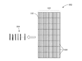
下記の詳細説明において本明細書の一部を形成し、説明、特定の実施形態又は実施例として示される添付の図面を参照する。ここで図面を参照する。幾つかの図面において同じ番号は同じ要素を表す。複合構成部品の三次元ランダム繊維配向の生成を説明する。複合繊維テープ102の上面図である図1Aに注目する。上述したように、熱可塑性材料は複合繊維テープ102に成形され、複合繊維テープ102は単向性の構成又は配向に配置された炭素繊維からできている。複合繊維テープ102は点線で示すように、フレーク104に切断される。当然ながら、図1Aに示す複合繊維テープ102では、あくまでも説明目的で限られた数のフレーク104が描写されている。従来は、フレーク104はほぼ正方形、又は長さと幅の縦横比が約1:1であるフレークに切断される。1:1でない場合、フレーク104の縦横比はしばしば2:1未満、又はその他何らかの「低い縦横比」の値であり、フレークの長さに対してかなり幅広いフレークが作られる。
In the following detailed description, reference is made to the accompanying drawings that form a part hereof, and which are shown by way of illustration, specific embodiments or examples. Reference is now made to the drawings. The same number represents the same element in several drawings. The generation of the three-dimensional random fiber orientation of the composite component is described. Attention is drawn to FIG. 1A, which is a top view of the
図1Bは繊維106の単向性の構成を示すフレーク104の拡大図である。繊維106と関連樹脂には、非限定的にPEKK、PEI、PEEK、PPE、及びPPSを含む好適な熱可塑性材料が含まれる。図から分かるように、繊維106は互いに実質的に平行に配向しており、単向性の構成の複合繊維テープ102と、対応するフレーク104となっている。
FIG. 1B is an enlarged view of
図2は、複合繊維テープ102の任意の数のフレーク104を用いた従来の圧縮成形システム200の断面図を示す。従来の圧縮成形システム200には、任意の数の構成部品の空洞204を有する型202が含まれる。構成部品の空洞204は、型202で作製される所望の構成部品に従って形作られ、サイズ指定されている。型202には、任意の数の通路と、様々な構成部品の空洞204に供給するためのターンが含まれる。複合材料を溶かすために加熱しながら、ラム208を使用してフレーク104を通路全体に押し込んで構成部品の空洞204を充填する。
FIG. 2 shows a cross-sectional view of a conventional
圧縮する前に、型202の容器206は、圧縮成形工程中に作製される完成構成部品の質量とほぼ等しい量のフレーク104で充填される。上述し図2に示すように、従来法の問題は、従来の低い縦横比の寸法特性を有するフレーク104によく見られる層状スタッキング210現象である。フレーク104を容器206に移す、又はそうでなければ配置する際に、フレーク104は比較的平坦に積み重なって層状スタッキング210ができやすい。フレーク104の層状スタッキング210により、実質的に二次元配向のフレーク104及び対応する繊維106ができる。
Prior to compression, the
フレーク104を加熱及び加圧すると、フレーク104の積層210構成が型202の構成部品の空洞204全体に押し付けられる。この加熱及び圧縮工程により、フレーク104が通路の角周囲に押し付けられた時に、フレーク104又はフレーク104のスタックの平面配向が曲がる又は変化するが、層状スタッキング210は型202の一又は複数の領域に存在し続ける。構成部品の空洞204内の層状スタッキング210により構成部品の潜在的に弱い領域212ができ、せん断力又は張力に晒された場合に、フレークがバラバラになる、又はそうでなければフレークのスタックが剥離する。図2はフレーク104の層状スタッキング210と、発生した弱い領域212の一例を示すために大幅に簡略化されていることに注意すべきである。
When the
本発明の一実施形態が記載されている図3に注目する。フレーク104の層状スタッキング210を防止するために、本明細書に記載した概念により、フレーク104又は対応する複合繊維テープ102を、幅狭フレーク作製機構302を介して幅狭フレーク304に変形させる。幅狭フレーク作製機構302の実施形態を、図6に関して下に説明する。幅狭フレーク304は、下にさらに詳しく説明するように、型202の容器206に移した時に、所望の縦横比310が得られ、これにより三次元ランダム繊維配向の幅狭フレーク204が最終的にできるような長さ306及び幅308を有する。所望の縦横比310は、従来のフレーク104に関する縦横比よりもかなり大きいものである。上述したように、従来の縦横比は約1:1〜4:1である。様々な実施形態によれば、所望の縦横比は6:1又はそれ以上である。 つまり、一実施形態によれば、幅狭フレーク304の長さ306は、幅狭フレーク304の幅308の少なくとも六倍である。一実施形態によれば、所望の縦横比310は約8:1である。例えば、幅狭フレーク304の長さ306は1/2インチであり、幅208は1/16インチであり、幅狭フレーク304の縦横比は8:1となる。
Attention is directed to FIG. 3, which describes one embodiment of the present invention. To prevent layered stacking 210 of
図4を参照する。幅狭フレーク304を型202の容器206に移すと、所望の縦横比310により、幅狭フレーク304が三次元ランダム繊維配向に実質的に配置される。この三次元ランダム繊維配向では、実質的に単向性である、幅狭フレーク304それぞれの中の繊維106が、隣接した大部分の幅狭フレーク304の繊維106と実質的に平行していない。つまり、幅狭フレーク304は従来のフレーク104でよく見られる層状スタッキング210ではなく、全ての平面にわたって全方向に延在する。こうすれば、幅狭フレーク304が加熱され型202の通路、及び構成部品の空洞204全体に押し付けられた際に、三次元ランダム繊維配向の幅狭フレーク304が実質的に維持される。
Please refer to FIG. When the
完成した構成部品は等方性強度特性を有し、構成部品には層状スタッキング210による特定方向に弱い領域212が全く発生しない。加えて、完成した構成部品は、上述した同じ型202及びフレーク104を使用して圧縮成形された同一の構成部品と比較して、強度特性が強化される。これは、幅狭フレーク304により、繊維106が構成部品全体で一貫して全方向に位置づけされるからである。加熱及び加圧して幅狭フレーク304を型202全体に押し付ける前に、繊維106を三次元にインターレースすることによって、冷却後の型202と完成した構成部品全体のランダム繊維配向の分布が確実となる。
The completed component has isotropic strength characteristics, and the component does not have any
図5は、一又は複数の細切刃504を有する混合装置502を含む幅狭フレーク作製機構の一実施形態を示す。この実施形態によれば、複合繊維テープ102を上述したようにフレーク104に切断する。次にフレーク104を、一又は複数の細切刃504によってフレーク104に打撃を加える工業用ミキサー又はその他の装置等の混合装置502に配置する。フレーク104と接触すると、細切刃504からの衝撃力によりフレーク104が繊維106に対して平行な軸に沿って破砕し、同じ長さ306を有するが元のフレーク104よりも幅308が短い複数のフレーク104ができる。フレーク104の破砕は、大部分のフレーク104が所望の縦横比310に対応する十分短い幅308を有して、幅狭フレーク304が出来上がるまで継続される。
FIG. 5 illustrates one embodiment of a narrow flake making mechanism that includes a
この幅狭フレーク作製機構302の使用により、全体的に均一でない幅狭フレーク304が作製される。一例として、大部分の幅狭フレーク304の縦横比が8:1である一方で、その他の幅狭フレークの縦横比は6:1〜10:1である。この幅狭フレークの不均一性は、特定用途によっては望ましい、又は望ましくない場合がある。幅狭フレーク304の約75%の縦横比310が約6:1以上である限り、型202の容器206に充填される幅狭フレーク304は三次元ランダム繊維配向となる。一実施形態によれば、完成した構成部品内の幅狭フレークの少なくとも75%の縦横比が少なくとも6:1であれば、構成部品全体が実質的に三次元ランダム繊維配向となる。
By using this narrow
図6に示す代替実施形態によれば、幅狭フレーク作製機構302は、複合繊維テープ102又はフレーク104を幅狭フレーク304に細長く切る及び切断する装置及び/又は工程を含む。一実施形態によれば、複合繊維テープ102は、幅狭フレーク304の所望の幅308を有する幅狭テープリボン602に切り込まれる。複合繊維テープ102を細長く切った後で、幅狭テープリボン602は点線で示す所望の長さ306に切断され又は細切りされて、幅狭フレーク304が作製される。
According to an alternative embodiment shown in FIG. 6, the narrow
当然ながら、熱可塑性又はその他の複合繊維材料を細長く切る及び切断する全ての適切な機器を用いることが可能である。さらに、テープを所望の幅308に細長く切って幅狭フレーク304を作製する前に、複合繊維テープ102を幅狭フレーク304の長さ306に対応する所望の長さに切断する。複合繊維テープ102は、代替的に型打ちして縦及び横に同時に切断し、幅狭フレーク304を作製することができる。。代替実施形態によれば、比較的低い縦横比を有するフレーク104を、従来技術を使用して複合繊維テープ102から作製することができる。次にフレーク104の適切な箇所を細長く切って、約6:1又はそれ以上の縦横比を有する幅狭フレーク304を作製する。幅狭フレーク作製機構302の複数の実施形態を説明してきたが、当然ながら、幅狭フレーク作製機構302は、複合繊維テープ102及び/又は対応するフレーク104を所望の縦横比310を有する幅狭フレーク304を細長く切る、細切りする、切断する、又は別のやり方で変形させるように動作するすべての機械又は工程を含む。
Of course, any suitable device for slitting and cutting thermoplastic or other composite fiber materials can be used. Further, the
フレーク104を破砕して幅狭フレーク304にする代わりに、複合繊維テープ102を幅狭フレーク304に細長く切る及び切断する一つの潜在的な利点は、幅狭フレーク304全体又は任意の部分を所望の精確な長さ306及び幅308に切断できるということである。この複合構造部品内に含まれる幅狭フレーク304の精確性を制御することにより、所望の強度特性を有する均一の構成部品を一貫して作製することが可能になる。この細長く切る工程及び切断工程を用いる一実施形態によれば、完成構成部品内の実質的にすべての幅狭フレークの縦横比が少なくとも6:1となり、この結果、構成部品全体が実質的に三次元ランダム繊維配向となる。
Instead of crushing
作製される構成部品の特徴によって、型の一か所に特定の長さ306、幅308、及び対応する縦横比310を有する幅狭フレーク304のサブセットを使用する一方で、第1サブセットとは異なる長さ306、幅308、及び対応する縦横比310を有する幅狭フレーク304の第2サブセットを使用すると有利である。すなわち、様々な実施形態によれば、複合繊維テープ102を任意の数の幅狭テープリボン602に切断し、次にさらにどれもが同等の寸法属性又は様々な寸法属性を有する任意の数の幅狭フレーク304に切断する。
Depending on the characteristics of the component being produced, a subset of
本明細書に記載した工程及び構成部品は熱可塑性材料に関して説明されたが、幅狭フレーク304の作製が可能になる、及び容器206内で三次元配向された幅狭フレーク304を加熱し圧縮した時に、型202全体で三次元ランダム繊維配向の流れが可能になる特徴を有する他の材料に場合によっては適用可能であることを認識すべきである。本明細書に記載した実施形態は熱硬化性材料、及び氷点を上回る温度においてフレークの樹脂に架橋が起こり、その結果、粘度及びフレークの特性により、加熱中に三次元ランダム繊維配向を複雑な型のすべての構成部品の空洞全体に押し込むことができない性質を持つ材料には適用できない場合があることに注意すべきである。対照的に、熱可塑性材料及び類似の材料では、室温又は氷点を上回る温度、すなわち華氏50度以上で幅狭フレーク304が作製されるため、生産費が最小限に抑えられる。構成部品作製工程は次に、機械的な圧力及び熱を利用して行われ、その後完成した構成部品は使用可能である、又は冷却後にさらに処理が行われる。
Although the processes and components described herein have been described with respect to thermoplastic materials,
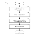
ここで図7に注目し、複合構成部品の三次元ランダム繊維配向を生じさせる手順700を詳しく説明する。図面で示し本明細書の説明に記載されるよりも多くの又は少ない作業が行われる場合があることを認識すべきである。これらの作業は本明細書で説明するのとは異なる順番で行うこともできる。
Turning now to FIG. 7, a
手順700は、作業702において開始し、作業702では、複合繊維テープ102を幅狭フレーク304に変形させる。複合繊維テープ102から幅狭フレーク304を作製する2つの異なる実施形態を、図8及び9に関して下に説明する。少なくとも6:1の縦横比を有する幅狭フレーク304が作製される。作業702から、手順700は作業704に続き、ここで幅狭フレーク304を型202の容器206に移す。幅狭フレーク304は少なくとも6:1の所望の縦横比310を有するため、幅狭フレーク304は容器206内で三次元ランダム繊維配向で静止する。幅狭フレーク304は容器206に移される時に隣接する幅狭フレーク304との結合が外れる場合があることを注意すべきである。つまり、フレークが室温、また一般に氷点を上回る温度において粘着性がある熱硬化性材料への適用と違い、幅狭フレーク304は氷点を上回る温度においてほぐれて、又は個々に離れて容器206内に落ち、所望の三次元ランダム繊維配向が作製される。これは幅狭フレーク304が隣接する幅狭フレーク304に縛られていない又はそうでなければ引きつけられていないからである。
The
手順700は作業704から作業706へ続き、ここで容器206内の幅狭フレーク304に熱及び圧力を印加して、幅狭フレーク304を型202の構成部品の空洞204全体に押し込む。容器206内の幅狭フレーク304の三次元ランダム繊維配向により、このランダム配向が型202全体に広がり、完成した構成部品全体に一貫した強度特性が付与される。作業706において、構成部品は型202から外す前に少なくとも部分的に冷却され固化して、手順700は終了する。
The
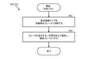
図8は、複合繊維テープ102を幅狭フレーク304に変形させる図7の作業702に対応する手順800を示す。この実施形態の一例を、フレーク104を破砕して幅狭フレーク304にする混合装置502の使用に関して図5に示す。手順800は作業802で開始し、ここで複合繊維テープ102をフレーク104、又は低縦横比フレークに切断する。作業804において、フレーク104を混合装置502内で混合し、細切刃504でフレーク104に打撃を加え、繊維106間のフレーク104を破砕して所望の縦横比310を有する幅狭フレーク304を作製して手順800が終了する。当然のことながら、この実施形態は混合装置502の使用に限定されない。むしろ、フレーク104に打撃を加えて、又はそうでなければフレーク104に十分な力を加えてフレーク104を破砕して幅狭フレーク304にするように構成されたすべての機器を使用することができる。
FIG. 8 shows a procedure 800 corresponding to
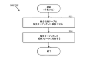
図9は、複合繊維テープ102を幅狭フレーク304に変形させる図7の作業702に対応する代替手順900を示す。複合繊維テープ102を一又は複数の所望の縦横比310を有する幅狭フレーク304を細長く切る及び切断することに関して、この実施形態の一例を図6に示す。手順900は作業902において開始し、ここで複合繊維テープ102を幅狭テープリボン602に細長く切る。幅狭テープリボン602の一又は複数の幅は、作製される幅狭フレーク304の所望の幅308に対応する。作業904において、幅狭テープリボン602を作製している幅狭フレーク304の所望の長さ306に対応する一又は複数の長さに切断し、手順900は終了する。
FIG. 9 shows an alternative procedure 900 corresponding to
前述した内容に基づいて、複合構成部品に三次元ランダム繊維配向を生じさせる技術が本明細書に記載されていることを認識すべきである。上に述べられた内容は図面のみにより提供されているが、これに限定するものと解釈されるべきではない。図示され説明が加えられた実施形態や適用例に正確に従わなくとも、本発明の開示の真の精神と範囲から逸脱しなければ、ここで述べられた内容に対し、様々な修正や変更が行われてもよく、このことは後に続く請求の範囲で明記される。 Based on the foregoing, it should be recognized that techniques for producing a three-dimensional random fiber orientation in a composite component are described herein. What has been described above is provided by way of illustration only and should not be construed as limiting. Various modifications and changes may be made to what has been described herein without departing from the true spirit and scope of the present disclosure without precisely following the illustrated and described embodiments and applications. This may be done and is specified in the claims that follow.
本発明の一態様により、複合構成部品に三次元ランダム繊維配向を生じさせる方法が提供されており、この方法は、単向性の複合繊維テープの複数の幅狭フレークを型容器に移すことを含み、複数の幅狭フレークはそれぞれ隣接する幅狭フレークとの結合から外れており、複数の幅狭フレークのうちの少なくとも大部分の縦横比は少なくとも6:1である。この方法はさらに、型容器内で複数の幅狭フレークを加熱し、容器内の複数の幅狭フレークを型全体に圧縮して複合構成部品を作製することを含む。 According to one aspect of the present invention, a method is provided for producing a three-dimensional random fiber orientation in a composite component, the method comprising transferring a plurality of narrow flakes of a unidirectional composite fiber tape to a mold container. In addition, each of the plurality of narrow flakes is out of combination with an adjacent narrow flake, and at least a majority of the plurality of narrow flakes has an aspect ratio of at least 6: 1. The method further includes heating the plurality of narrow flakes in the mold container and compressing the plurality of narrow flakes in the container into the entire mold to produce a composite component.
単向性の複合繊維テープが単向性の熱可塑性テープを含む上に開示した方法はさらに、単向性の熱可塑性テープを6:1未満の縦横比を有する複数のフレークに切断し、複数のフレークを繊維の軸線に沿って破砕して複数の幅狭フレークを作製することを含む。 The method disclosed above wherein the unidirectional composite fiber tape comprises a unidirectional thermoplastic tape further cuts the unidirectional thermoplastic tape into a plurality of flakes having an aspect ratio of less than 6: 1. Crushing the flakes along the fiber axis to produce a plurality of narrow flakes.
複数のフレークを繊維の軸線に沿って破砕して複数の幅狭フレークを作製する上に開示した方法は、複数のフレークを複数の細切刃を有する混合装置で複数のフレークのうちの大部分が少なくとも6:1の縦横比を含むまで混合して、複数の幅狭フレークを作製することを含む。 The method disclosed above for crushing a plurality of flakes along the fiber axis to produce a plurality of narrow flakes is obtained by mixing a plurality of flakes with a mixing device having a plurality of fine cutting blades. Mixing until producing an aspect ratio of at least 6: 1 to produce a plurality of narrow flakes.
単向性の複合繊維テープが単向性の熱可塑性テープを含む上に開示した方法はさらに、単向性の熱可塑性テープを複数の幅狭テープリボンに細長く切り、複数の幅狭テープリボンをおおよそ等しい寸法属性を有する複数の幅狭フレークに切断することを含む。 The method disclosed above wherein the unidirectional composite fiber tape comprises a unidirectional thermoplastic tape further cuts the unidirectional thermoplastic tape into a plurality of narrow tape ribbons, Cutting into a plurality of narrow flakes having approximately equal dimensional attributes.
単向性の複合繊維テープが単向性の熱可塑性テープを含む上に開示した方法がさらに、単向性の熱可塑性テープを複数の幅狭テープリボンに細長く切り、複数の幅狭テープリボンを複数の寸法属性を有する複数の幅狭フレークに切断することを含む。 The method disclosed above, wherein the unidirectional composite fiber tape comprises a unidirectional thermoplastic tape, further cuts the unidirectional thermoplastic tape into a plurality of narrow tape ribbons to form a plurality of narrow tape ribbons. Cutting into a plurality of narrow flakes having a plurality of dimensional attributes.
上に開示した方法では、8:1の縦横比が実質的に含まれる。 The method disclosed above substantially includes an 8: 1 aspect ratio.
上に開示した方法では、複数の幅狭フレークはおおよそ長さが1/2インチ、幅が1/16インチの幅狭フレークが含まれる。 In the method disclosed above, the plurality of narrow flakes includes narrow flakes that are approximately 1/2 inch long and 1/16 inch wide.
上に開示した方法では、複数の幅狭フレークを容器内で圧縮した後の型全体の複数の幅狭フレークの配向には、実質的に三次元ランダム繊維配向が含まれる。 In the method disclosed above, the orientation of the plurality of narrow flakes throughout the mold after compressing the plurality of narrow flakes in a container substantially includes a three-dimensional random fiber orientation.
上に開示した方法では、単向性の複合繊維テープは、少なくとも1つのPEKK、PEI、PEEK、PPE、及びPPSの炭素繊維強化樹脂を有する単向性の熱可塑性テープを含む。 In the method disclosed above, the unidirectional composite fiber tape comprises a unidirectional thermoplastic tape having at least one PEKK, PEI, PEEK, PPE, and PPS carbon fiber reinforced resin.
本発明の一態様により、複合構成部品に三次元ランダム繊維配向を生じさせる方法が提供されており、この方法は、単向性の熱可塑性テープを複数の幅狭フレークに変形させるステップであって、複数の幅狭フレークのうちの少なくとも大部分の縦横比は少なくとも6:1であるステップと、容器内の複数の幅狭フレークの配向が実質的に三次元ランダム繊維配向を含むように、型の容器に複数の幅狭フレークを移すステップと、複数の幅狭フレークを容器内で加熱し、複数の幅狭フレークを型全体の容器内で圧縮するステップを含む。 According to one aspect of the invention, a method is provided for producing a three-dimensional random fiber orientation in a composite component, the method comprising deforming a unidirectional thermoplastic tape into a plurality of narrow flakes. A step wherein the aspect ratio of at least a majority of the plurality of narrow flakes is at least 6: 1 and the orientation of the plurality of narrow flakes in the container substantially comprises a three-dimensional random fiber orientation Transferring the plurality of narrow flakes to the container, heating the plurality of narrow flakes in the container, and compressing the plurality of narrow flakes in the container of the entire mold.
上に開示した方法では、単向性の熱可塑性テープを複数の幅狭フレークに変形させるステップが、単向性の熱可塑性テープを2:1未満の縦横比を有する複数のフレークに切断し、複数のフレークを繊維の軸線に沿って破砕して、複数の幅狭フレークを作製することを含む。 In the method disclosed above, transforming the unidirectional thermoplastic tape into a plurality of narrow flakes cuts the unidirectional thermoplastic tape into a plurality of flakes having an aspect ratio of less than 2: 1. Crushing the plurality of flakes along the fiber axis to produce a plurality of narrow flakes.
上に開示した方法では、複数のフレークを繊維の軸線に沿って破砕して複数の幅狭フレークを作製するステップが、複数のフレークのうちの大部分の縦横比が少なくとも6:1になるまで、複数のフレークを複数の細切刃を有する混合装置で混合して複数の幅狭フレークを作製することを含む。 In the method disclosed above, the step of crushing the plurality of flakes along the fiber axis until the plurality of narrow flakes is produced has a majority aspect ratio of at least 6: 1. , Mixing a plurality of flakes with a mixing device having a plurality of fine cutting blades to produce a plurality of narrow flakes.
上に開示した方法では、単向性の熱可塑性テープを複数の幅狭フレークに変形させるステップが、単向性の熱可塑性テープを複数の幅狭テープリボンに細長く切り、複数の幅狭テープリボンをほぼ等しい寸法属性を有する複数の幅狭フレークに切断することを含む。 In the method disclosed above, the step of transforming the unidirectional thermoplastic tape into a plurality of narrow flakes comprises cutting the unidirectional thermoplastic tape into a plurality of narrow tape ribbons, A plurality of narrow flakes having substantially equal dimensional attributes.
上に開示した方法では、単向性の熱可塑性テープを複数の幅狭フレークに変形させるステップが、単向性の熱可塑性テープを複数の幅狭テープリボンに細長く切り、複数の幅狭テープリボンを複数の寸法属性を有する複数の幅狭フレークに切断することを含む。 In the method disclosed above, the step of transforming the unidirectional thermoplastic tape into a plurality of narrow flakes comprises cutting the unidirectional thermoplastic tape into a plurality of narrow tape ribbons, Cutting into a plurality of narrow flakes having a plurality of dimensional attributes.
上に開示した方法では、縦横比には実質的に8:1が含まれる。 In the method disclosed above, the aspect ratio substantially includes 8: 1.
上に開示した方法では、複数の幅狭フレークを容器内で圧縮した後の型全体の複数の幅狭フレークの配向は、実質的に三次元ランダム繊維配向を含む。 In the method disclosed above, the orientation of the plurality of narrow flakes throughout the mold after compressing the plurality of narrow flakes in a container comprises substantially a three-dimensional random fiber orientation.
本発明の一態様により、複合構成部品に三次元ランダム繊維配向を生じさせる方法が提供されており、この方法は、単向性の熱可塑性テープを複数の幅狭テープリボンに細長く切り、複数の幅狭テープリボンを切断して少なくとも6:1の縦横比を有する複数の幅狭フレークを作製し、複数の幅狭フレークを型の容器に移し、容器内の複数の幅狭フレークを加熱し、容器内の複数の幅狭フレークを圧縮して型に充填し、複合構成部品を作製することを含む。 According to one aspect of the present invention, a method is provided for producing a three-dimensional random fiber orientation in a composite component, the method comprising slicing a unidirectional thermoplastic tape into a plurality of narrow tape ribbons, Cutting a narrow tape ribbon to produce a plurality of narrow flakes having an aspect ratio of at least 6: 1; transferring the plurality of narrow flakes to a mold container; heating the plurality of narrow flakes in the container; Compressing and filling a plurality of narrow flakes in a container into a mold to produce a composite component.
上に説明した方法では、複数の幅狭テープリボンを切断して少なくとも6:1の縦横比を有する複数の幅狭フレークを作製するステップが、複数の幅狭テープリボンをほぼ等しい寸法属性を有する複数の幅狭フレークに切断することを含む。 In the method described above, the step of cutting the plurality of narrow tape ribbons to produce a plurality of narrow flakes having an aspect ratio of at least 6: 1 has substantially the same dimensional attributes as the plurality of narrow tape ribbons. Cutting into a plurality of narrow flakes.
上に開示した方法では、複数の幅狭テープリボンを切断して少なくとも6:1の縦横比を有する複数の幅狭フレークを作製するステップが、複数の幅狭テープリボンを複数の寸法属性を有する複数の幅狭フレークに切断することを含む。 In the method disclosed above, cutting a plurality of narrow tape ribbons to produce a plurality of narrow flakes having an aspect ratio of at least 6: 1 has the plurality of narrow tape ribbons having a plurality of dimensional attributes. Cutting into a plurality of narrow flakes.
上に開示した方法では、複数の幅狭フレークを型の容器に移すステップが、型内の複数の幅狭フレークの配向が実質的に三次元ランダム繊維配向からなるように型の容器に複数の幅狭フレークを移すことを含み、複数の幅狭フレークの縦横比には少なくとも8:1が含まれる。 In the method disclosed above, the step of transferring the plurality of narrow flakes to the mold container comprises: Transferring the narrow flakes, the aspect ratio of the plurality of narrow flakes including at least 8: 1.
本発明の一態様は、単向性の熱可塑性テープの複数の幅狭フレークを含む複合構成部品を提供し、複数の幅狭フレークのうちの少なくとも75%は少なくとも6:1の縦横比を含む。 One aspect of the present invention provides a composite component comprising a plurality of narrow flakes of unidirectional thermoplastic tape, wherein at least 75% of the plurality of narrow flakes comprises an aspect ratio of at least 6: 1. .
上に開示した複合構成部品では、少なくとも6:1の縦横比を含む複数の幅狭フレークのうちの少なくとも75%が、三次元ランダム繊維配向に従って実質的に配向されている。 In the composite component disclosed above, at least 75% of the plurality of narrow flakes comprising an aspect ratio of at least 6: 1 are substantially oriented according to a three-dimensional random fiber orientation.
102 単向性の複合繊維テープ
104 複数のフレーク
106 繊維
200 従来の圧縮成形システム
202 型
204 構成部品の空洞
206 容器
208 ラム
210 層状スタッキング
212 構成部品の潜在的に弱い領域
302 幅狭フレーク作製機構
304 幅狭フレーク
306 幅狭フレークの長さ
308 幅狭フレークの幅
310 縦横比
502 混合装置
504 細切刃
602 幅狭テープリボン
700 複合構成部品の三次元ランダム繊維配向を生じさせる手順
800 図7の作業702に対応する手順
900 図7の作業702に対応する代替手順
102 Unidirectional
Claims (9)
前記複数の幅狭フレーク304を前記型容器206内で加熱するステップ706と、
前記複数の幅狭フレーク304を前記型容器206内で前記型容器206全体に圧縮して706、前記複合構成部品を作製するステップ
を含む方法。 A method of producing a three-dimensional random fiber orientation in a composite component, wherein the plurality of narrow flakes 304 of the unidirectional composite fiber tape 102 is transferred to a mold container 206 702, wherein the plurality of narrow flakes 304 are transferred. Each of which is decoupled from adjacent narrow flakes 304, at least a majority of the plurality of narrow flakes 304 having an aspect ratio of at least 6: 1;
Heating the plurality of narrow flakes 304 in the mold vessel 206;
Compressing the plurality of narrow flakes 304 into the entire mold container 206 within the mold container 206 to produce the composite component 706.
前記単向性の熱可塑性テープを6:1未満の縦横比を有する複数のフレーク104に切断するステップ802と、
前記複数のフレーク104を前記繊維の軸線に沿って破砕して804、前記複数の幅狭フレーク304を作製するステップ
をさらに含む、請求項1に記載の方法。 The unidirectional composite fiber tape 102 comprises a unidirectional thermoplastic tape;
Cutting the unidirectional thermoplastic tape into a plurality of flakes 104 having an aspect ratio of less than 6: 1;
The method of claim 1, further comprising crushing the plurality of flakes 104 along the fiber axis 804 to produce the plurality of narrow flakes 304.
前記複数のフレーク104のうちの大部分が少なくとも6:1の縦横比を含むまで前記複数のフレーク104を複数の細切刃504を有する混合装置502で混合して前記複数の幅狭フレーク304を作製するステップ804を含む、請求項2に記載の方法。 Crushing the plurality of flakes 104 along the axis of the fibers 104 to produce the plurality of narrow flakes 304;
The plurality of flakes 104 are mixed with a mixing device 502 having a plurality of fine cutting edges 504 until the majority of the plurality of flakes 104 includes an aspect ratio of at least 6: 1 to form the plurality of narrow flakes 304. The method of claim 2, comprising creating 804.
Applications Claiming Priority (2)
| Application Number | Priority Date | Filing Date | Title |
|---|---|---|---|
| US13/356,132 | 2012-01-23 | ||
| US13/356,132 US10603821B2 (en) | 2012-01-23 | 2012-01-23 | Narrow flake composite fiber material compression molding |
Related Child Applications (1)
| Application Number | Title | Priority Date | Filing Date |
|---|---|---|---|
| JP2017152111A Division JP6490757B2 (en) | 2012-01-23 | 2017-08-07 | Compression molding of narrow flaky composite fiber materials |
Publications (2)
| Publication Number | Publication Date |
|---|---|
| JP2013163377A true JP2013163377A (en) | 2013-08-22 |
| JP2013163377A5 JP2013163377A5 (en) | 2016-03-03 |
Family
ID=47598703
Family Applications (3)
| Application Number | Title | Priority Date | Filing Date |
|---|---|---|---|
| JP2013010233A Pending JP2013163377A (en) | 2012-01-23 | 2013-01-23 | Narrow flake composite fiber material compression molding |
| JP2017152111A Active JP6490757B2 (en) | 2012-01-23 | 2017-08-07 | Compression molding of narrow flaky composite fiber materials |
| JP2019033816A Active JP6783336B2 (en) | 2012-01-23 | 2019-02-27 | Compression molding method for narrow flake composite fiber material |
Family Applications After (2)
| Application Number | Title | Priority Date | Filing Date |
|---|---|---|---|
| JP2017152111A Active JP6490757B2 (en) | 2012-01-23 | 2017-08-07 | Compression molding of narrow flaky composite fiber materials |
| JP2019033816A Active JP6783336B2 (en) | 2012-01-23 | 2019-02-27 | Compression molding method for narrow flake composite fiber material |
Country Status (6)
| Country | Link |
|---|---|
| US (3) | US10603821B2 (en) |
| EP (1) | EP2617556B1 (en) |
| JP (3) | JP2013163377A (en) |
| CN (3) | CN107521121B (en) |
| ES (1) | ES2604034T3 (en) |
| PT (1) | PT2617556T (en) |
Families Citing this family (16)
| Publication number | Priority date | Publication date | Assignee | Title |
|---|---|---|---|---|
| US8709319B2 (en) | 2009-11-06 | 2014-04-29 | The Boeing Company | Compression molding method and reinforced thermoplastic parts molded thereby |
| US9393745B2 (en) * | 2012-05-15 | 2016-07-19 | Hexcel Corporation | Over-molding of load-bearing composite structures |
| US9238339B2 (en) | 2013-02-21 | 2016-01-19 | The Boeing Company | Hybrid fastener and method of making the same |
| US9623612B2 (en) | 2013-02-21 | 2017-04-18 | The Boeing Company | Method for fabricating composite fasteners |
| WO2015057270A1 (en) * | 2013-10-15 | 2015-04-23 | United Technologies Corporation | Compression molded fiber reinforced fan case ice panel |
| US9302434B2 (en) | 2013-12-03 | 2016-04-05 | The Boeing Company | Thermoplastic composite support structures with integral fittings and method |
| US9283706B2 (en) | 2013-12-03 | 2016-03-15 | The Boeing Company | Method and apparatus for compression molding fiber reinforced thermoplastic parts |
| US20160101543A1 (en) * | 2013-12-03 | 2016-04-14 | The Boeing Company | Hybrid Laminate and Molded Composite Structures |
| US10286623B2 (en) | 2015-06-15 | 2019-05-14 | Lockheed Martin Corporation | Composite materials with tapered reinforcements |
| DE102015014752A1 (en) * | 2015-11-13 | 2017-05-18 | Audi Ag | Method for producing a fiber composite component and fiber composite component |
| WO2019046218A1 (en) | 2017-08-28 | 2019-03-07 | Web Industries, Inc. | Thermoplastic composite master sheets and tapes and method |
| US11305859B2 (en) | 2018-03-28 | 2022-04-19 | The Boeing Company | Method for forming a composite structure |
| KR102329572B1 (en) * | 2018-07-12 | 2021-11-23 | 애리스 컴포지트 아이엔씨. | Methods and compositions for compression molding |
| US11628632B2 (en) * | 2019-03-25 | 2023-04-18 | The Boeing Company | Pre-consolidated charges of chopped fiber for composite part fabrication |
| GB201908265D0 (en) * | 2019-06-10 | 2019-07-24 | Rolls Royce Plc | Lay-up apparatus |
| EP3789437A1 (en) * | 2019-09-06 | 2021-03-10 | Burckhardt Compression AG | Sealing element and / or support ring made of compression-moulded carbon fibre-reinforced composite material |
Citations (8)
| Publication number | Priority date | Publication date | Assignee | Title |
|---|---|---|---|---|
| JPH02143810A (en) * | 1988-11-24 | 1990-06-01 | Toray Ind Inc | Compound board of thermoplastic resin and reinforcing fiber |
| JPH0397759A (en) * | 1989-09-11 | 1991-04-23 | Takeshi Yamashita | Production of composite material consisting essentially of wood flake, and production device for the same product and wood flake |
| JPH05278126A (en) * | 1992-04-02 | 1993-10-26 | Toyobo Co Ltd | Forming material of fiber reinforced thermoplastic resin |
| JP2002331521A (en) * | 2001-05-10 | 2002-11-19 | Tomoyuki Kasahara | Laminated plate different in color and hardness containing waste material as main material |
| JP2004142165A (en) * | 2002-10-22 | 2004-05-20 | Toyobo Co Ltd | Compression molding material |
| JP2010100851A (en) * | 2008-10-23 | 2010-05-06 | Campagnolo Spa | Sheet molding compound |
| JP2012051225A (en) * | 2010-09-01 | 2012-03-15 | Toyobo Co Ltd | Compression molding method of fiber-reinforced thermoplastic resin sheet |
| JP2013510013A (en) * | 2009-11-06 | 2013-03-21 | ザ・ボーイング・カンパニー | Compression molding method and reinforced thermoplastic parts molded by the same molding method |
Family Cites Families (28)
| Publication number | Priority date | Publication date | Assignee | Title |
|---|---|---|---|---|
| US3646610A (en) | 1969-03-10 | 1972-02-29 | True Temper Corp | Fiber glass reinforced golf shaft |
| US3705837A (en) * | 1970-06-16 | 1972-12-12 | Grace W R & Co | Woodflake composition for panels and method of making same |
| JPS5642533A (en) * | 1979-09-12 | 1981-04-20 | Mitsubishi Rayon Co | Fishing reel and production thereof |
| US4287020A (en) * | 1979-11-29 | 1981-09-01 | Moore Irving F | Method of preparation of an asbestos product |
| US4370390A (en) | 1981-06-15 | 1983-01-25 | Mcdonnell Douglas Corporation | 3-D Chopped-fiber composites |
| US4414011A (en) | 1982-05-25 | 1983-11-08 | United Technologies Corporation | Method of securing fiber reinforced glass matrix composite material to structural members |
| US4983451A (en) | 1987-08-05 | 1991-01-08 | Kabushiki Kaisha Kobe Seiko Sho | Carbon fiber-reinforced carbon composite material and process for producing the same |
| GB8806915D0 (en) * | 1988-03-23 | 1988-04-27 | Blatchford & Sons Ltd | Moulding compound & method of manufacturing compound |
| US4925719A (en) | 1988-04-08 | 1990-05-15 | Centrite Corp. | Reinforced polymeric composites |
| IL95489A0 (en) | 1989-08-31 | 1991-06-30 | Du Pont | Nonwoven preform sheets of fiber reinforced resin |
| US5569424A (en) * | 1995-03-09 | 1996-10-29 | Amour; William E. | Method and apparatus for recycling waste composite material |
| AU680804B3 (en) | 1996-12-17 | 1997-08-07 | William Everett Amour | Method for recycling waste composite material |
| FR2770802B1 (en) * | 1997-11-13 | 2000-02-11 | Duqueine | PROCESS FOR MOLDING A COMPOSITE PART, COMPOSITE STRUCTURE USED IN THIS PROCESS AND HANDLE OBTAINED ACCORDING TO THIS PROCESS |
| US6521152B1 (en) | 2000-03-16 | 2003-02-18 | Honeywell International Inc. | Method for forming fiber reinforced composite parts |
| FR2806425B1 (en) | 2000-03-16 | 2002-07-12 | Hexcel Composites | COMPOSITE INTERMEDIATE PRODUCT, PROCESS FOR PRODUCING SUCH A PRODUCT, AND USE AS A MOLDING MATERIAL |
| EP1167001B1 (en) * | 2000-06-26 | 2005-05-11 | SAERTEX Wagener GmbH & Co. KG | Process for making webs, strips and chips having multiple filamentary carbon fibres |
| JP2002344011A (en) | 2001-05-15 | 2002-11-29 | Sony Corp | Display element and display unit using the same |
| US6924021B1 (en) * | 2002-07-03 | 2005-08-02 | Trek Bicycle Corporation | Complex-shaped carbon fiber structural member and its method of manufacture |
| GB0222753D0 (en) * | 2002-10-02 | 2002-11-06 | Carbon Fibre Technology Ltd | Method of production of advanced composite materials |
| US7198739B2 (en) | 2004-05-25 | 2007-04-03 | Honeywell International Inc. | Manufacture of thick preform composites via multiple pre-shaped fabric mat layers |
| US7960674B2 (en) * | 2005-06-28 | 2011-06-14 | Hexcel Corporation | Aerospace articles made from quasi-isotropic chopped prepreg |
| US8962737B2 (en) * | 2008-03-27 | 2015-02-24 | Gordon Holdings, Inc. | Composite coated substrates and moldable composite materials |
| JP4712830B2 (en) | 2008-06-19 | 2011-06-29 | 日立オートモティブシステムズ株式会社 | Vehicle control device |
| WO2010010584A1 (en) * | 2008-07-24 | 2010-01-28 | Alenia Aeronautica S.P.A. | A method for recycling scraps of prepreg materials |
| CN102271905B (en) * | 2009-01-06 | 2015-02-18 | 塞特克技术公司 | Structural composite material with improved acoustic and vibrational damping properties |
| US8663524B2 (en) | 2009-05-12 | 2014-03-04 | Miller Waste Mills | Controlled geometry composite micro pellets for use in compression molding |
| ES2658182T3 (en) | 2010-03-15 | 2018-03-08 | Gfsi Group Llc | Recycled composite materials and related methods |
| US8529809B2 (en) * | 2011-09-22 | 2013-09-10 | The Boeing Company | Compression molding of composite material quasi-isotropic flakes |
-
2012
- 2012-01-23 US US13/356,132 patent/US10603821B2/en active Active
-
2013
- 2013-01-18 PT PT131519118T patent/PT2617556T/en unknown
- 2013-01-18 ES ES13151911.8T patent/ES2604034T3/en active Active
- 2013-01-18 EP EP13151911.8A patent/EP2617556B1/en not_active Revoked
- 2013-01-23 CN CN201710705776.7A patent/CN107521121B/en active Active
- 2013-01-23 CN CN201710594393.7A patent/CN107253332B/en active Active
- 2013-01-23 CN CN2013100248708A patent/CN103213283A/en active Pending
- 2013-01-23 JP JP2013010233A patent/JP2013163377A/en active Pending
-
2017
- 2017-08-07 JP JP2017152111A patent/JP6490757B2/en active Active
-
2019
- 2019-02-27 JP JP2019033816A patent/JP6783336B2/en active Active
- 2019-11-01 US US16/672,133 patent/US10919192B2/en active Active
- 2019-11-01 US US16/672,021 patent/US10919191B2/en active Active
Patent Citations (9)
| Publication number | Priority date | Publication date | Assignee | Title |
|---|---|---|---|---|
| JPH02143810A (en) * | 1988-11-24 | 1990-06-01 | Toray Ind Inc | Compound board of thermoplastic resin and reinforcing fiber |
| JP2507565B2 (en) * | 1988-11-24 | 1996-06-12 | 東レ株式会社 | Composite board of thermoplastic resin and reinforcing fiber |
| JPH0397759A (en) * | 1989-09-11 | 1991-04-23 | Takeshi Yamashita | Production of composite material consisting essentially of wood flake, and production device for the same product and wood flake |
| JPH05278126A (en) * | 1992-04-02 | 1993-10-26 | Toyobo Co Ltd | Forming material of fiber reinforced thermoplastic resin |
| JP2002331521A (en) * | 2001-05-10 | 2002-11-19 | Tomoyuki Kasahara | Laminated plate different in color and hardness containing waste material as main material |
| JP2004142165A (en) * | 2002-10-22 | 2004-05-20 | Toyobo Co Ltd | Compression molding material |
| JP2010100851A (en) * | 2008-10-23 | 2010-05-06 | Campagnolo Spa | Sheet molding compound |
| JP2013510013A (en) * | 2009-11-06 | 2013-03-21 | ザ・ボーイング・カンパニー | Compression molding method and reinforced thermoplastic parts molded by the same molding method |
| JP2012051225A (en) * | 2010-09-01 | 2012-03-15 | Toyobo Co Ltd | Compression molding method of fiber-reinforced thermoplastic resin sheet |
Also Published As
| Publication number | Publication date |
|---|---|
| JP6490757B2 (en) | 2019-03-27 |
| US10919192B2 (en) | 2021-02-16 |
| CN107521121B (en) | 2019-08-30 |
| JP6783336B2 (en) | 2020-11-11 |
| JP2018020568A (en) | 2018-02-08 |
| ES2604034T3 (en) | 2017-03-02 |
| JP2019142228A (en) | 2019-08-29 |
| US20200061881A1 (en) | 2020-02-27 |
| EP2617556B1 (en) | 2016-09-28 |
| US20200061880A1 (en) | 2020-02-27 |
| CN107521121A (en) | 2017-12-29 |
| PT2617556T (en) | 2016-10-20 |
| US10603821B2 (en) | 2020-03-31 |
| CN103213283A (en) | 2013-07-24 |
| EP2617556A1 (en) | 2013-07-24 |
| CN107253332B (en) | 2019-08-30 |
| CN107253332A (en) | 2017-10-17 |
| US20130189478A1 (en) | 2013-07-25 |
| US10919191B2 (en) | 2021-02-16 |
Similar Documents
| Publication | Publication Date | Title |
|---|---|---|
| JP6490757B2 (en) | Compression molding of narrow flaky composite fiber materials | |
| KR102185890B1 (en) | Resin composition, filament and resin powder for 3D printer, and sculpture and method for manufacturing the same | |
| KR101643114B1 (en) | Layered substrate and method for manufacturing same | |
| JP5920227B2 (en) | Method for producing carbon fiber reinforced plastic | |
| JP6075094B2 (en) | Method for producing molded product having rib structure | |
| KR102344759B1 (en) | Infeed prepreg and manufacturing method of infeed prepreg | |
| WO2015194533A1 (en) | Method for manufacturing molded article having opening, and molded article | |
| JP2016172840A (en) | Soluble nanoparticles for composite performance enhancement | |
| JP2014067924A (en) | Method for manufacturing thermal conductive sheet | |
| KR102147808B1 (en) | Manufacturing method for plate type specimens for physical properties evaluation using powder bed fusion | |
| JP5987603B2 (en) | Manufacturing method of heat conductive sheet | |
| JP5994100B2 (en) | Manufacturing method of heat conductive sheet | |
| US11331890B1 (en) | Polymeric sandwich structure having enhanced thermal conductivity and method of manufacturing the same | |
| JP2013184356A (en) | Fiber-reinforced resin base material, and method of manufacturing resin molding and resin processing machine for carrying out the same | |
| JP2017061714A (en) | High-thermal conductivity composite material | |
| CN105774179A (en) | Self-fixturing metallic composite laminate | |
| JP7147046B2 (en) | Method for manufacturing press-formed body | |
| KR20130106200A (en) | Thermoplastic composite for easy impregnation and manufacture method thereof | |
| JP2016103554A (en) | Heat radiating material and method of manufacturing the same | |
| JP2929908B2 (en) | Manufacturing method of plate-shaped molded products | |
| KR101900826B1 (en) | Mehtod for manufacturing continuous fiber-reinforced sheet, the continuous fiber-reinforced sheet, mehtod for manufacturing board using the continuous fiber-reinforced sheet | |
| JP2016087907A (en) | Method for producing fiber-reinforced plastic | |
| JP2015009436A (en) | Fiber-reinforced resin molding, and method for producing the same | |
| WO2014208576A1 (en) | Apparatus for cutting fiber-reinforced resin | |
| JP2014067923A (en) | Thermal conductive sheet |
Legal Events
| Date | Code | Title | Description |
|---|---|---|---|
| A521 | Request for written amendment filed |
Free format text: JAPANESE INTERMEDIATE CODE: A523 Effective date: 20160113 |
|
| A621 | Written request for application examination |
Free format text: JAPANESE INTERMEDIATE CODE: A621 Effective date: 20160113 |
|
| A977 | Report on retrieval |
Free format text: JAPANESE INTERMEDIATE CODE: A971007 Effective date: 20161026 |
|
| A131 | Notification of reasons for refusal |
Free format text: JAPANESE INTERMEDIATE CODE: A131 Effective date: 20161101 |
|
| A601 | Written request for extension of time |
Free format text: JAPANESE INTERMEDIATE CODE: A601 Effective date: 20170131 |
|
| A601 | Written request for extension of time |
Free format text: JAPANESE INTERMEDIATE CODE: A601 Effective date: 20170331 |
|
| A521 | Request for written amendment filed |
Free format text: JAPANESE INTERMEDIATE CODE: A523 Effective date: 20170428 |
|
| A02 | Decision of refusal |
Free format text: JAPANESE INTERMEDIATE CODE: A02 Effective date: 20170606 |