JP2013156533A5 - - Google Patents
Download PDFInfo
- Publication number
- JP2013156533A5 JP2013156533A5 JP2012018346A JP2012018346A JP2013156533A5 JP 2013156533 A5 JP2013156533 A5 JP 2013156533A5 JP 2012018346 A JP2012018346 A JP 2012018346A JP 2012018346 A JP2012018346 A JP 2012018346A JP 2013156533 A5 JP2013156533 A5 JP 2013156533A5
- Authority
- JP
- Japan
- Prior art keywords
- fixed
- lens barrel
- flexible substrate
- fixed cylinder
- shutter
- Prior art date
- Legal status (The legal status is an assumption and is not a legal conclusion. Google has not performed a legal analysis and makes no representation as to the accuracy of the status listed.)
- Granted
Links
- 239000000758 substrate Substances 0.000 claims description 16
- 230000003287 optical Effects 0.000 claims description 4
- 238000003384 imaging method Methods 0.000 claims 4
- 230000002093 peripheral Effects 0.000 claims 2
Images

Description
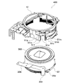
上記目的を達成するために、本願発明のレンズ鏡筒は、第1の鏡筒と、シャッターの駆動部を有する第2の鏡筒とを光軸方向に移動可能に支持する固定筒と、前記シャッターの前記駆動部に接続される第1の接続部と、前記第1の接続部に連結部を介して接続される第2の接続部とを有するシャッターフレキシブル基板と、前記固定筒と、前記第1の鏡筒及び第2の鏡筒を駆動する駆動手段とを支持する支持部材とを備えるレンズ鏡筒であって、前記固定筒には、前記シャッターフレキシブル基板の前記連結部を挿通させる切り欠き部が形成されるとともに、前記シャッターフレキシブル基板の前記連結部に形成された孔に嵌合する固定軸が径方向外側に突出して形成され、前記支持部材には、前記固定筒の前記固定軸が前記シャッターフレキシブル基板の前記連結部の前記孔に嵌合された状態における前記連結部の前記固定筒の径方向外側への移動を規制する移動規制部が形成されることを特徴とする。 In order to achieve the above object, a lens barrel according to the present invention includes a first barrel and a fixed barrel that supports a second barrel having a shutter drive unit movably in the optical axis direction, A shutter flexible substrate having a first connection portion connected to the driving portion of the shutter, and a second connection portion connected to the first connection portion via a connecting portion; the fixed cylinder; a lens barrel Ru and a support member for supporting the driving means for driving the first barrel and a second barrel, wherein the fixed cylinder is inserting the said connecting portion of the shutter flexible substrate with notches are made form, the fixed shaft to be fitted into a hole formed in the connecting portion of the shutter flexible substrate is formed to project radially outward, the the support member, prior to the fixed cylindrical serial fixed axis of the shutter frame Wherein the movement restricting portion for restricting the movement of the radially outer side of the fixed barrel of the connecting portion in the fitted state into the hole of the connecting portion of the reluctance substrate.
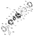
また、鏡筒フレキシブル基板8には、シャッターフレキシブル基板20の接続部20b(図3参照)を接続するための接続部8cと、不図示のカメラ本体の電気部品と接続するための接続部8dとが設けられている。接続部8dによりカメラの操作情報がレンズ鏡筒700に送信され、レンズ鏡筒700が動作する。
Further, the lens barrel flexible substrate 8 has a connection portion 8c for connecting a
シャッター羽根12にはシャッター地板11に回転可能に支持される孔12aと図示しない長孔が形成され、シャッター羽根13には孔13aと長孔13bが形成されている。シャッター羽根12は、孔12aにおいて中間シートを介してシャッター地板11に回転可能に支持され、長孔においてシャッター・ND駆動部17に回転可能に支持されている。シャッター羽根13は、孔13aにおいて中間シート14を介してシャッター地板11に回転可能に支持され、長孔13bにおいてシャッター・ND駆動部17に回転可能に連結されている。
The
バリア羽根38,39は、バリア駆動リング35とバリアカバー41との間に配置されている。バリア羽根38,39には、軸38a,39aが形成され、軸38a,39aは、1群筒31の支持孔31c,31dに回転可能に支持される。バリア羽根38,39が軸38a,39aを支点に回転することで、バリアカバー41の開口部40aを開閉する。 The barrier blades 38 and 39 are disposed between the barrier drive ring 35 and the barrier cover 41. The barrier blades 38 and 39 are formed with shafts 38a and 39a, and the shafts 38a and 39a are rotatably supported by the support holes 31c and 31d of the first group cylinder 31. Barrier blades 38 and 39 by rotating shaft 38a, a 39a as a fulcrum to open and close the opening 40a of the burr A cover 41.
Claims (10)
前記シャッターの前記駆動部に接続される第1の接続部と、前記第1の接続部に連結部を介して接続される第2の接続部とを有するシャッターフレキシブル基板と、
前記固定筒と、前記第1の鏡筒及び第2の鏡筒を駆動する駆動手段とを支持する支持部材とを備えるレンズ鏡筒であって、
前記固定筒には、前記シャッターフレキシブル基板の前記連結部を挿通させる切り欠き部が形成されるとともに、前記シャッターフレキシブル基板の前記連結部に形成された孔に嵌合する固定軸が径方向外側に突出して形成され、
前記支持部材には、前記固定筒の前記固定軸が前記シャッターフレキシブル基板の前記連結部の前記孔に嵌合された状態における前記連結部の前記固定筒の径方向外側への移動を規制する移動規制部が形成されることを特徴とするレンズ鏡筒。 A fixed barrel that supports a first barrel and a second barrel having a shutter drive unit so as to be movable in the optical axis direction;
A shutter flexible board having a first connection part connected to the drive part of the shutter, and a second connection part connected to the first connection part via a connecting part;
Wherein a fixed cylinder, a lens barrel Ru and a support member for supporting and driving means for driving said first barrel and a second barrel,
Wherein the fixed cylinder, the said connecting portion of the shutter flexible substrate with notches for inserting is made form a fixed axis radially outward for fitting into a hole formed in the connecting portion of the shutter flexible substrate Formed to protrude
Wherein the support member to restrict movement before Symbol fixed axis of the fixed barrel radially outward of the fixed cylinder of the connecting portion in the fitted state into the hole of the connecting portion of the shutter flexible substrate A lens barrel having a movement restricting portion.
前記固定軸は、前記壁部に形成されることを特徴とする請求項3に記載のレンズ鏡筒。 The wall is formed on the subject side of the notch ,
The lens barrel according to claim 3, wherein the fixed shaft is formed on the wall portion.
前記レンズ鏡筒として、請求項1乃至4のいずれか1項に記載のレンズ鏡筒を備えることを特徴とする撮像装置。 An imaging device comprising a lens barrel,
As the lens barrel, an imaging apparatus comprising: a lens barrel according to any one of claims 1 to 4.
前記光駆動部に接続されるフレキシブル基板と、A flexible substrate connected to the optical drive unit;
前記固定筒を支持する支持部材とを備えるレンズ鏡筒であって、A lens barrel provided with a support member for supporting the fixed cylinder,
前記固定筒には、切り欠き部及び固定部が形成され、The fixed cylinder is formed with a notch and a fixed part,
前記フレキシブル基板は、前記切り欠き部を介して前記固定筒の外側に導出され、The flexible substrate is led out to the outside of the fixed cylinder through the notch,
前記切り欠き部を介して導出されたフレキシブル基板の一部は、前記固定部において固定され、A part of the flexible substrate led out through the notch is fixed at the fixing part,
前記支持部材には、移動規制部が形成され、A movement restricting portion is formed on the support member,
前記移動規制部は、前記切り欠き部を介して導出されたフレキシブル基板の一部が、前記固定筒の径方向外側への移動を規制することを特徴とするレンズ鏡筒。The movement restricting portion restricts the movement of a part of the flexible substrate led out through the cutout portion to the radially outer side of the fixed tube.
前記固定軸は、前記フレキシブル基板に形成された孔に嵌合し、The fixed shaft is fitted into a hole formed in the flexible substrate,
前記移動規制部は、前記固定軸が挿入される切り抜き部を有することを特徴とする請求項6に記載のレンズ鏡筒。The lens barrel according to claim 6, wherein the movement restricting portion has a cutout portion into which the fixed shaft is inserted.
前記壁部と前記移動規制部によって前記フレキシブル基板の収納空間が画成されることを特徴とする請求項6又は7に記載のレンズ鏡筒。The lens barrel according to claim 6 or 7, wherein a storage space for the flexible substrate is defined by the wall portion and the movement restricting portion.
前記固定部は前記壁部に形成されることを特徴とする請求項8に記載のレンズ鏡筒。The lens barrel according to claim 8, wherein the fixing portion is formed on the wall portion.
前記レンズ鏡筒として、請求項6乃至9のいずれか1項に記載のレンズ鏡筒を備えることを特徴とする撮像装置。An imaging apparatus comprising the lens barrel according to any one of claims 6 to 9 as the lens barrel.
Priority Applications (3)
| Application Number | Priority Date | Filing Date | Title |
|---|---|---|---|
| JP2012018346A JP5893420B2 (en) | 2012-01-31 | 2012-01-31 | Lens barrel and imaging device including the same |
| CN201310035318.9A CN103226230B (en) | 2012-01-31 | 2013-01-30 | Lens barrel having shutter flexible circuit board and image pickup apparatus having the same |
| US13/755,495 US8734032B2 (en) | 2012-01-31 | 2013-01-31 | Lens barrel having shutter flexible circuit board and image pickup apparatus having the same |
Applications Claiming Priority (1)
| Application Number | Priority Date | Filing Date | Title |
|---|---|---|---|
| JP2012018346A JP5893420B2 (en) | 2012-01-31 | 2012-01-31 | Lens barrel and imaging device including the same |
Publications (3)
| Publication Number | Publication Date |
|---|---|
| JP2013156533A JP2013156533A (en) | 2013-08-15 |
| JP2013156533A5 true JP2013156533A5 (en) | 2015-03-19 |
| JP5893420B2 JP5893420B2 (en) | 2016-03-23 |
Family
ID=48836732
Family Applications (1)
| Application Number | Title | Priority Date | Filing Date |
|---|---|---|---|
| JP2012018346A Expired - Fee Related JP5893420B2 (en) | 2012-01-31 | 2012-01-31 | Lens barrel and imaging device including the same |
Country Status (3)
| Country | Link |
|---|---|
| US (1) | US8734032B2 (en) |
| JP (1) | JP5893420B2 (en) |
| CN (1) | CN103226230B (en) |
Families Citing this family (9)
| Publication number | Priority date | Publication date | Assignee | Title |
|---|---|---|---|---|
| JP5893420B2 (en) * | 2012-01-31 | 2016-03-23 | キヤノン株式会社 | Lens barrel and imaging device including the same |
| CN103943032B (en) | 2014-04-01 | 2016-03-02 | 京东方科技集团股份有限公司 | A kind of array base palte and display device |
| JP6348757B2 (en) * | 2014-04-14 | 2018-06-27 | オリンパス株式会社 | Light adjusting device and method for measuring distance between substrates of light adjusting device |
| US10511754B2 (en) | 2014-08-01 | 2019-12-17 | Nidec Copal Corporation | Imaging apparatus, optical device, electronic device, vehicle, and imaging-device manufacturing method |
| KR102652992B1 (en) * | 2018-04-11 | 2024-04-01 | 엘지이노텍 주식회사 | Lens Moving Apparatus |
| JP7373853B2 (en) * | 2018-06-08 | 2023-11-06 | 株式会社nittoh | Lens barrel and interchangeable lens camera |
| CN109451205A (en) * | 2018-10-15 | 2019-03-08 | 信利光电股份有限公司 | A kind of novel camera module |
| CN114666474A (en) * | 2019-09-30 | 2022-06-24 | 深圳市大疆创新科技有限公司 | Camera and movable platform |
| JP7446907B2 (en) * | 2020-05-11 | 2024-03-11 | キヤノン株式会社 | Optical equipment and imaging devices |
Family Cites Families (17)
| Publication number | Priority date | Publication date | Assignee | Title |
|---|---|---|---|---|
| US4864348A (en) * | 1987-09-03 | 1989-09-05 | Canon Kabushiki Kaisha | Structure for installing flexible printed circuit board |
| JPH0753052Y2 (en) * | 1989-05-22 | 1995-12-06 | 旭光学工業株式会社 | Lens flexible board mounting structure |
| US5717969A (en) * | 1993-10-21 | 1998-02-10 | Nikon Corporation | Lens barrel with flexible printed circuit boards |
| US5559571A (en) * | 1994-01-20 | 1996-09-24 | Nikon Corporation | Lens barrel and electric circuit board connection structure |
| JPH10170807A (en) * | 1996-12-06 | 1998-06-26 | Nikon Corp | Camera |
| JP3782652B2 (en) * | 2000-08-31 | 2006-06-07 | ペンタックス株式会社 | FPC arrangement structure of zoom lens barrel |
| JP2002277923A (en) * | 2001-03-22 | 2002-09-25 | Asahi Optical Co Ltd | Fpc arrangement structure for lens shutter, and fpc arrangement structure |
| JP2005326631A (en) * | 2004-05-14 | 2005-11-24 | Optech:Kk | Lens barrel |
| JP4855001B2 (en) * | 2005-07-25 | 2012-01-18 | Hoya株式会社 | Imaging module |
| JP2007114532A (en) * | 2005-10-20 | 2007-05-10 | Sony Corp | Lens barrel |
| JP4595783B2 (en) * | 2005-10-20 | 2010-12-08 | ソニー株式会社 | Lens barrel |
| JP4921087B2 (en) * | 2006-09-08 | 2012-04-18 | キヤノン株式会社 | Flexible board fixing device |
| JP2008225430A (en) | 2007-02-14 | 2008-09-25 | Canon Inc | Lens barrel unit |
| JP4948318B2 (en) * | 2007-08-08 | 2012-06-06 | キヤノン株式会社 | Lens barrel and imaging device |
| JP5515622B2 (en) * | 2009-10-28 | 2014-06-11 | パナソニック株式会社 | Lens barrel and lens barrel |
| JP2012137526A (en) * | 2010-12-24 | 2012-07-19 | Canon Inc | Lens barrel |
| JP5893420B2 (en) * | 2012-01-31 | 2016-03-23 | キヤノン株式会社 | Lens barrel and imaging device including the same |
-
2012
- 2012-01-31 JP JP2012018346A patent/JP5893420B2/en not_active Expired - Fee Related
-
2013
- 2013-01-30 CN CN201310035318.9A patent/CN103226230B/en not_active Expired - Fee Related
- 2013-01-31 US US13/755,495 patent/US8734032B2/en not_active Expired - Fee Related
Similar Documents
| Publication | Publication Date | Title |
|---|---|---|
| JP2013156533A5 (en) | ||
| JP2013047787A5 (en) | ||
| JP2013025156A5 (en) | ||
| TWI626850B (en) | Camera module | |
| JP2012118346A5 (en) | ||
| JP2012133040A5 (en) | ||
| JP6494243B2 (en) | Imaging device | |
| JP2015141278A5 (en) | ||
| JP2012058560A5 (en) | ||
| JP2005321696A5 (en) | ||
| JP5335467B2 (en) | Lens barrel | |
| JP2008040114A5 (en) | ||
| JP2016005375A5 (en) | ||
| JP2010113092A (en) | Actuator, blade driving device, and optical apparatus | |
| JP2011164506A (en) | Light quantity adjusting device and imaging apparatus having the same | |
| JP2014102331A5 (en) | ||
| JP2011102857A5 (en) | ||
| JP2005227329A5 (en) | ||
| JP5978101B2 (en) | Focal plane shutter and optical equipment | |
| JP2014006467A5 (en) | ||
| JP2006215421A5 (en) | ||
| JP2007057897A (en) | Aperture diaphragm device | |
| JP5207798B2 (en) | Electromagnetic actuator | |
| JP2012037693A5 (en) | ||
| JP2010109502A5 (en) |