JP2013151315A - Corrugated cardboard box - Google Patents
Corrugated cardboard box Download PDFInfo
- Publication number
- JP2013151315A JP2013151315A JP2012014187A JP2012014187A JP2013151315A JP 2013151315 A JP2013151315 A JP 2013151315A JP 2012014187 A JP2012014187 A JP 2012014187A JP 2012014187 A JP2012014187 A JP 2012014187A JP 2013151315 A JP2013151315 A JP 2013151315A
- Authority
- JP
- Japan
- Prior art keywords
- side plate
- cardboard box
- tear
- perforation
- corrugated cardboard
- Prior art date
- Legal status (The legal status is an assumption and is not a legal conclusion. Google has not performed a legal analysis and makes no representation as to the accuracy of the status listed.)
- Granted
Links
Images


Abstract
Description
本発明は、改良された引裂帯を有する段ボール箱に関する。更に詳しくは、引裂帯を利用して段ボール箱を開封したとき、引裂き面が、表層剥離を伴うことなく良好な外観を有し、したがって、段ボール箱の中に収納された物品を小売店頭で陳列するに際し、段ボール箱から物品を取り出すことなく、そのまま陳列することができる、改良された引裂帯を有する段ボール箱に関する。 The present invention relates to a cardboard box having an improved tear strip. More specifically, when the cardboard box is opened using a tear strip, the tear surface has a good appearance without accompanying surface peeling, and therefore the articles stored in the cardboard box are displayed at the retail store front. In doing so, the present invention relates to a cardboard box having an improved tear strip that can be displayed as it is without taking out an article from the cardboard box.
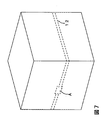
従来から、小巻にした食品包装用ラップフィルムを収納した化粧箱、小分けした菓子等の食品を収納した化粧箱、飲料等を詰めた容器等の比較的小さな物品を集積包装し、運搬するために、紙製の、典型的には段ボール製の箱が使用されている。また、紙箱に集積包装された物品を小売店頭において陳列するとき、物品を箱から取り出すことなく陳列することができるように、紙箱に引裂帯を設けることが広く行われている。引裂帯とは、例えば図7に示されるように、紙箱側面の中腹などを一周に亘って帯状に引裂いて箱を開封することができるように紙箱の側板に周方向にミシン目などを設けたものである。従来の引裂帯では、引裂き開始部(A)が、図7に示されるように、ある一枚の側板のミシン目の長手方向の中央部分に設けられている。このような引裂帯は、引裂き作業の容易性は良好であるものの、引裂き作業の確実さや安全性および、陳列時のための引裂き面のきれいさの点では十分とは言えない。 Conventionally, for packing and transporting relatively small items such as cosmetic boxes containing small wrapped food packaging wrap films, cosmetic boxes containing small confectionery foods, containers filled with beverages, etc. In addition, paper, typically cardboard boxes are used. In addition, when displaying articles stacked and packed in a paper box at a retail store, it is widely practiced to provide a tear strip on the paper box so that the articles can be displayed without being taken out of the box. For example, as shown in FIG. 7, the tear band is provided with perforations or the like in the circumferential direction on the side plate of the paper box so that the box can be opened by tearing the middle of the side of the paper box over the entire circumference. Is. In the conventional tear band, the tear start portion (A) is provided in the central portion in the longitudinal direction of the perforation of a certain side plate, as shown in FIG. Although such a tear band is easy to tear, it is not sufficient in terms of the reliability and safety of the tearing work and the cleanness of the tearing surface for display.
さらに、上記紙箱には十分な強度が必要である。搬送時においては、配送方面毎に仕分けするために、傾斜面を通って移送させたりすることが行われるので、これに耐える強度が要求される。また、搬送時や保管時においては、紙箱は段積みされるため、これにより紙箱が座屈したりしないだけの耐荷重が要求される。 Furthermore, the paper box needs to have sufficient strength. At the time of conveyance, in order to sort for each delivery direction, it is transferred through an inclined surface, so that strength to withstand this is required. Further, since the paper boxes are stacked at the time of transportation and storage, a load resistance that does not cause the paper boxes to buckle is required.
引裂帯を利用する開封を容易かつ確実に行うための技術として、例えば、段ボールの裏側原紙に罫線を入れ、その同一直線上に切れ目が断続するライナカット線を設けることが提案されている(例えば特許文献1)。また、ミシン目又は罫線を直線状ではなく、曲線状にすることも知られている(例えば特許文献2)。しかし、これらの技術では、開封は容易になるものの、開封面(引裂き面)のきれいさと箱の強度とを併せて満足することは難しい。 As a technique for easily and reliably performing opening using a tear band, for example, it has been proposed to put a ruled line on the back side base paper of a corrugated cardboard, and to provide a liner cut line on which the cut is interrupted (for example, Patent Document 1). It is also known that perforations or ruled lines are not linear but curved (for example, Patent Document 2). However, with these techniques, opening becomes easy, but it is difficult to satisfy both the cleanness of the opening surface (tear surface) and the strength of the box.
本発明の目的は、引裂帯を有する段ボール箱であって、十分な耐荷重および強度を有し、引裂きが容易で、かつ引裂き後の引裂き面がきれいであるところの段ボール箱を提供することである。 An object of the present invention is to provide a corrugated cardboard box having a tear strip, which has sufficient load resistance and strength, is easy to tear, and has a clean tear surface after tearing. is there.
本発明者らは、鋭意研究した結果、引裂帯の引裂き開始部を特定の箇所に設け、ミシン目又は罫線を正弦波形状にし、かつ特定の箇所にはミシン目又は罫線を設けないことにより、上記目的を達成できることを見出した。 As a result of earnest research, the present inventors have provided a tear start portion of a tear band at a specific location, a perforation or a ruled line in a sine wave shape, and a specific location without a perforation or a ruled line, It has been found that the above object can be achieved.
すなわち、本発明は、直方体の段ボール箱であって、連接した4枚の側板からなる胴部、各側板の上端縁から延出した4枚の蓋部フラップおよび各側板の下端縁から延出した4枚の底部フラップを有し、上記胴部を形成する側板の1枚が、その側端縁から延出する糊代用フラップを有し、上記1枚の側板が上記糊代用フラップを介して他の1枚の側板と接着により接続して胴部が形成されているところの段ボール箱において、上記胴部をその周方向に引裂くことができるように各側板の略中央部に周方向に正弦波形状のミシン目または罫線を有し、上記他の1枚の側板の、上記糊代用フラップとの接着部分に引裂き開始のためのミシン目または罫線を有する、ただし各側板は、上記引裂き開始部を除いて、側板同士の連接部およびその近接部にミシン目および罫線を有しない、ことを特徴とする段ボール箱である。 That is, the present invention is a rectangular parallelepiped corrugated cardboard box, which is extended from a trunk portion composed of four connected side plates, four lid flaps extending from the upper edge of each side plate, and a lower edge of each side plate. One side plate that has four bottom flaps and that forms the body portion has a paste substitute flap that extends from the side edge, and the one side plate is another via the paste substitute flap. In the corrugated cardboard box in which the body portion is formed by bonding to one side plate of the plate, the body portion is sine in the circumferential direction at a substantially central portion of each side plate so that the body portion can be torn in the circumferential direction. A corrugated perforation or ruled line, and a perforation or a ruled line for starting tearing at an adhesive portion of the other one side plate with the paste substitute flap, provided that each side plate has the tear start portion Except for, the connecting part between side plates and its proximity part Perforations and having no ruled line, a cardboard box, characterized in that.
本発明の段ボール箱は、十分な耐荷重および強度を有するとともに、引裂きが容易である。また、引裂き後の引裂き面がきれいであるので、段ボール箱の中に集積包装された物品を小売店頭で陳列するに際し、箱から物品を取り出すことなく、そのまま陳列することができる。 The cardboard box of the present invention has sufficient load resistance and strength and is easy to tear. In addition, since the tear surface after tearing is clean, when the articles collected and packaged in the cardboard box are displayed at the retail store front, they can be displayed as they are without taking out the articles from the box.
本発明の段ボール箱を、図を参照して説明する。図1は、本発明の段ボール箱の展開図の一例を示す図であり、図2は、本発明の段ボール箱の一例を示す斜視図である。本発明の段ボール箱は直方体であり、連接した4枚の側板からなる胴部、各側板の上端縁から延出した蓋部フラップ(6)および各側板の下端縁から延出した底部フラップ(7)を有する。上記段ボール箱は、図1に示すように、胴部を形成する側板の1枚(図1では(4))がその側端縁から延出する糊代用フラップ(5)を有し、上記1枚の側板が、この糊代用フラップを介して他の1枚の側板(図1では(1))と接着して接続することにより胴部が形成される。図1では、側板(4)の側端縁に糊代用フラップが設けられているが、側板(1)の側端縁に設けてもよい。本発明の段ボール箱は、蓋部フラップ(6)および底部フラップ(7)をそれぞれ、側板との境界線で折りたたむことにより、上面および下面が閉じられて箱として完成される。4枚の側板の大きさは、直方体の胴部を形成することができるかぎり、互いに同じでも異なっていてもよい。 The cardboard box of the present invention will be described with reference to the drawings. FIG. 1 is a diagram showing an example of a development view of the cardboard box of the present invention, and FIG. 2 is a perspective view showing an example of the cardboard box of the present invention. The corrugated cardboard box of the present invention is a rectangular parallelepiped, and is composed of a body part comprising four connected side plates, a lid flap (6) extending from the upper edge of each side plate, and a bottom flap (7) extending from the lower edge of each side plate. ). As shown in FIG. 1, the cardboard box has a paste substitute flap (5) in which one of the side plates ((4) in FIG. 1) forming the body portion extends from the side edge, The body part is formed by bonding and connecting the one side plate to the other side plate ((1) in FIG. 1) through the adhesive substitute flap. In FIG. 1, the paste substitute flap is provided at the side edge of the side plate (4), but it may be provided at the side edge of the side plate (1). The cardboard box of the present invention is completed as a box with the top and bottom surfaces closed by folding the lid flap (6) and the bottom flap (7) at the boundary line with the side plate, respectively. The size of the four side plates may be the same as or different from each other as long as a rectangular parallelepiped body can be formed.
図2は、図1と同様に側板(4)の側端縁に設けられた糊代用フラップ(5)を介して側板(4)と側板(1)が接続されて胴部が形成されている、本発明の段ボール箱の一例を示す斜視図である。 In FIG. 2, the side plate (4) and the side plate (1) are connected to each other through a paste substitute flap (5) provided at the side edge of the side plate (4), as in FIG. 1, thereby forming a body portion. It is a perspective view which shows an example of the cardboard box of this invention.
本発明の段ボール箱は、図1および2に示されるように、各側板の略中央部に周方向にミシン目または罫線(8)が設けられており、上記ミシン目または罫線に沿って段ボール箱を引裂くことができるようになっている。なお、段ボール原紙は、表側原紙と裏側原紙との間に波状の中芯を挟んで接着したものである。段ボール箱を容易かつきれいに引裂くことができるように、上記ミシン目または罫線は、表側原紙と裏側原紙の両方に設けられる。 As shown in FIGS. 1 and 2, the corrugated cardboard box according to the present invention is provided with a perforation or ruled line (8) in the circumferential direction at a substantially central portion of each side plate, and the cardboard box along the perforation or ruled line. Can be torn. The corrugated cardboard is obtained by adhering a corrugated core between the front side base paper and the back side base paper. The perforations or ruled lines are provided on both the front side paper and the back side base paper so that the cardboard box can be easily and cleanly torn.
図3は、図2の段ボール箱をミシン目(8)に沿って引裂いたときの状態を示す斜視図であり、図4は、図3において上下2つに引裂かれた段ボール箱の上方部分を取り除いた状態を示す斜視図である。本明細書において、「引裂き面」は、ミシン目(8)に沿って上下2つに引裂かれた段ボール箱の上方部分を取り除いて残った下方部分の上端面を意味し、図4の番号9で示される部分である。 FIG. 3 is a perspective view showing a state when the cardboard box of FIG. 2 is torn along the perforation (8), and FIG. 4 shows an upper portion of the cardboard box torn into two upper and lower parts in FIG. It is a perspective view which shows the state removed. In the present specification, the “tear surface” means the upper end surface of the lower part remaining after removing the upper part of the corrugated cardboard box that has been torn in the upper and lower directions along the perforation (8). This is the part indicated by
上記ミシン目または罫線の形状は、図1および2に示されるように、正弦波形状である。段ボール箱を単に引裂くだけならば、ミシン目または罫線は直線状であってもよい。しかし、箱の中に収納されるものが重量物であるときに要求される耐荷重や段ボール箱の搬送時や保管時に要求される強度を考慮すると、上記形状は正弦波形状であるのが好ましい。上記形状が直線状であると、引裂き方向も直線状であり、搬送時や保管時にその方向に大きな力が作用すると、段ボール箱が座屈するなどの問題を生じ得る。この問題を解決するためには、引裂き方向を直線状ではなく、適宜違えるようにすればよく、そのためには、鋸歯状が考えられる。しかし、この場合には、引裂き方向が不連続に変化するので、きれいに引裂くことが困難である。上記形状が正弦波形状であれば、容易かつきれいに引裂くことができるとともに、強度も確保され、座屈等のトラブルが軽減される。 The perforation or ruled line has a sine wave shape as shown in FIGS. If the cardboard box is simply torn, the perforations or ruled lines may be straight. However, considering the load resistance required when the object stored in the box is heavy and the strength required when transporting or storing the cardboard box, the shape is preferably a sine wave shape. . If the shape is linear, the tearing direction is also linear, and if a large force acts in that direction during transportation or storage, problems such as buckling of the cardboard box may occur. In order to solve this problem, the tearing direction may be appropriately changed instead of being linear, and for this purpose, a sawtooth shape is conceivable. However, in this case, since the tear direction changes discontinuously, it is difficult to cleanly tear. If the shape is a sinusoidal shape, it can be easily and neatly teared, the strength is secured, and troubles such as buckling are reduced.
図5は、ミシン目又は罫線(8)の形状を説明する図である。正弦波の波長をL、波高をHとするとき、Hは、要求される耐荷重や強度および使用する段ボール原紙の質にもよるが、5mm以上が好ましく、より好ましくは10mm以上である。また、強度の確保の点から、波高Hに対する波長Lの比(L/H)が小さい方が好ましく、一方、引裂き易さの点から、上記比は大きい方が好ましい。両者のバランスを考慮すると、波長Lが波高Hの3〜6倍であるのが好ましい。具体的には、例えば、波高Hが10mmであり、波長Lが40mmである。 FIG. 5 is a diagram for explaining the shape of the perforation or the ruled line (8). When the wavelength of the sine wave is L and the wave height is H, H is preferably 5 mm or more, more preferably 10 mm or more, although it depends on the required load resistance and strength and the quality of the corrugated base paper used. Further, from the viewpoint of securing strength, it is preferable that the ratio of the wavelength L to the wave height H (L / H) is small, while from the viewpoint of easy tearing, the ratio is preferably large. Considering the balance between them, the wavelength L is preferably 3 to 6 times the wave height H. Specifically, for example, the wave height H is 10 mm and the wavelength L is 40 mm.
本発明の段ボール箱は、図1および2に示されるように、引裂き開始部(A)が、側板(1)の、糊代用フラップ(5)と接着している部分にある。一般に、引裂帯を利用した箱の開封では、引裂帯の引裂き開始部にあるミシン目を割って開始片を形成し、開始片を掴んで箱の引裂きが行われるので、箱の開始片周辺には大きな力がかかる。したがって、引裂き開始部周辺の強度が弱いと、引裂き後の引裂き面のきれいさに欠ける。本発明の段ボール箱は、引裂き開始部が、側板の、糊代用フラップ(5)との接着部分にある。この部分は段ボール紙が二重になっているので、強度を確保することができ、したがって、引裂き後の引裂き面がきれいである。なお、糊代用フラップ(5)の幅Wは特に制限されないが、通常、25〜50mm程度である。 As shown in FIGS. 1 and 2, the corrugated cardboard box of the present invention has a tear start portion (A) at a portion where the side plate (1) is bonded to the adhesive substitute flap (5). In general, when opening a box using a tear band, the perforation at the tearing start part of the tear band is broken to form a starting piece, and the box is torn by grasping the starting piece. Takes great power. Therefore, if the strength around the tear starting portion is weak, the tear surface after tearing is not clean. In the corrugated cardboard box of the present invention, the tearing start portion is at the adhesive portion of the side plate with the adhesive substitute flap (5). Since this portion is made of double corrugated paper, the strength can be ensured, and therefore the tear surface after tearing is clean. The width W of the paste substitute flap (5) is not particularly limited, but is usually about 25 to 50 mm.
また、引裂帯を利用して開封する作業中に引裂帯が千切れてしまうことを防止するために、段ボール箱の内側においてミシン目又は罫線(8)の上方にカットテープを設けてもよい。 Further, in order to prevent tearing of the tear band during the opening operation using the tear band, a cut tape may be provided above the perforation or the ruled line (8) inside the cardboard box.
さらに、段ボール箱の強度を確保するためには、隣接する2つの側板間の連接部の強度が重要である。上記連接部付近にミシン目または罫線があると、強度の確保が困難である。本発明の段ボール箱は、各側板が、上記引裂き開始部を除いて、側板同士の連接部およびその近接部にミシン目および罫線を有しないので、強度を確保することができる。各側板における、ミシン目および罫線を有しない範囲を、各側板のミシン目又は罫線の長さ方向の先端と側板同士の連接部との最短距離αで表わすとき(図1参照)、αは、段ボール原紙の質にもよるが、各々独立して、10mm以上であるのが好ましく、より好ましくは20mm以上である。一方、ミシン目および罫線がない部分は、引裂きの容易性や引裂いた後の引裂き面のきれいさを低下させるため、この部分の大きさ(α)は、できるだけ小さい方が好ましい。具体的には、段ボール原紙の質にもよるが、αは、各々独立して、40mm以下であるのが好ましく、より好ましくは38mm以下である。 Furthermore, in order to ensure the strength of the cardboard box, the strength of the connecting portion between two adjacent side plates is important. If there are perforations or ruled lines in the vicinity of the connecting part, it is difficult to ensure strength. In the cardboard box of the present invention, each side plate does not have perforations and ruled lines in the connecting portion between the side plates and its adjacent portion except for the tear start portion, so that strength can be ensured. When the range having no perforation and ruled line in each side plate is represented by the shortest distance α between the perforation of each side plate or the lengthwise direction of the ruled line and the connecting portion between the side plates (see FIG. 1), α is Although depending on the quality of the corrugated base paper, it is preferably independently 10 mm or more, more preferably 20 mm or more. On the other hand, the portion without the perforation and the ruled line reduces the ease of tearing and the cleanliness of the tear surface after tearing. Therefore, the size (α) of this portion is preferably as small as possible. Specifically, although depending on the quality of the corrugated cardboard, each α is preferably independently 40 mm or less, more preferably 38 mm or less.
段ボール原紙は、通常のものを使用することができるが、強度の点から、表側原紙および裏側原紙の坪量が各々、120〜469g/m2であるものが好ましい。 As the corrugated cardboard, ordinary ones can be used, but from the viewpoint of strength, those having a basis weight of 120 to 469 g / m 2 for the front side base paper and the back side base paper are preferable.
段ボール箱の大きさは、その中に収納される物の大きさや重さ及び収納個数を考慮して適宜選択される。このとき、収納物込みの段ボール箱の重さ(以下、「梱包質量」と言うことがある。)は、人力で運搬可能な範囲に抑える必要から、上限30Kg程度、好ましくは上限15Kg程度にすべきことを考慮する。例えば、小巻したラップフィルムを収納した化粧箱(52mm×2mm×314mm)を30本収納する場合には、段ボール箱の大きさが276mm×330mm×315mmであり、梱包質量が12.5Kgであり得る。 The size of the cardboard box is appropriately selected in consideration of the size and weight of items stored therein and the number of items stored therein. At this time, the weight of the corrugated cardboard box containing the stored items (hereinafter sometimes referred to as “packing mass”) is limited to a range that can be transported by human power, so the upper limit is about 30 kg, preferably the upper limit is about 15 kg. Consider what to do. For example, when storing 30 decorative boxes (52 mm × 2 mm × 314 mm) containing small rolls of wrap film, the size of the cardboard box is 276 mm × 330 mm × 315 mm, and the packing mass is 12.5 kg. obtain.
段ボール箱の製函は、人力で行ってもよく、公知の製函機を使用して行ってもよい。 Box making of cardboard boxes may be performed manually or using a known box making machine.
段ボール箱の糊代用フラップ(5)に使用される接着剤または粘着剤は、糊代用フラップ(5)と側板との接着部分を剥したときに、段ボール箱が材破するような接着または粘着強度を有するものであればどのようなものでも良い。例えば、アクリル系、エチレン酢酸ビニル系、酢酸ビニル系、ポリエステル系、ポリウレタン系、澱粉系、天然ゴム系、エポキシ樹脂系、酢酸セルロース系、ポリイソブチレン系、クロロプレンゴム系、スチレンブタジエンゴム系、ポリビニルアルコール系およびポリビニルピロリドン系などの慣用の粘着剤や接着剤が使用可能である。 The adhesive or pressure-sensitive adhesive used for the paste substitute flap (5) of the cardboard box is such that the cardboard box breaks when the adhesive portion between the paste substitute flap (5) and the side plate is peeled off. As long as it has, what kind of thing may be sufficient. For example, acrylic, ethylene vinyl acetate, vinyl acetate, polyester, polyurethane, starch, natural rubber, epoxy resin, cellulose acetate, polyisobutylene, chloroprene rubber, styrene butadiene rubber, polyvinyl alcohol Conventional pressure-sensitive adhesives and adhesives such as those based on polyvinyl and pyrrolidone can be used.
以下、実施例に基づいて本発明を具体的に説明するが、本発明は以下の実施例に限定されるものではない。 EXAMPLES Hereinafter, although this invention is demonstrated concretely based on an Example, this invention is not limited to a following example.
実施例1
短辺276mm×長辺330mm×高さ315mmの大きさの段ボール箱(坪量280g/m2のK7ライナー、Aフルート)であって、図2に示すように、正弦波形状のミシン目を各側板の略中央部分に設け、引裂き開始のためのミシン目(A)を図2に示すように設けたものに、小巻したラップフィルムを収納した化粧箱(高さ52mm×横52mm×長さ314mm)を30本梱包した。ミシン目の波高Hおよび波長L、ならびに長さαは表1に示す通りであり、梱包質量は12.5Kgであった。また、糊代用フラップ(5)の幅Wは35mmであった。この梱包体について、下記の試験を行った。結果を表1に示す。
Example 1
A corrugated cardboard box having a short side of 276 mm, a long side of 330 mm and a height of 315 mm (a K7 liner having a basis weight of 280 g / m 2 , an A flute), as shown in FIG. A decorative box (height 52 mm x width 52 mm x length) that is provided in the approximate center of the side plate and has a perforation (A) for starting tearing as shown in FIG. 314 mm) was packed. The perforation wave height H and wavelength L, and the length α were as shown in Table 1, and the packing mass was 12.5 kg. The width W of the paste substitute flap (5) was 35 mm. The following test was done about this package. The results are shown in Table 1.
試験
(1)耐荷重試験
東洋精機株式会社の圧縮試験機を使用し、JIS Z 0212 方法Aに準拠して、上記梱包体(収納物有)の耐荷重試験を行い、段ボール箱および収納物のそれぞれについて、以下の基準で評価した。
段ボール箱:
○:箱の変形を目視で確認できるのは1250Kgfを超える荷重をかけたときである。
△:750〜1250Kgfの荷重をかけると、箱の変形が目視で確認される。
×:750Kgf未満の荷重において、箱の変形が目視で確認される。
収納物:
○:収納物に目視で変形が認められるのは、1500Kgfを超える荷重をかけたときである。
△:1000〜1500Kgfの荷重をかけると、収納物の変形が目視で認められる。
×:1000Kgf未満の荷重において、収納物の変形が目視で認められる。
Test (1) Load-bearing test Using a compression tester manufactured by Toyo Seiki Co., Ltd., in accordance with JIS Z 0212 Method A, a load-bearing test of the package (with storage) is performed. Each was evaluated according to the following criteria.
Cardboard box:
○: The deformation of the box can be visually confirmed when a load exceeding 1250 kgf is applied.
Δ: When a load of 750 to 1250 kgf is applied, deformation of the box is visually confirmed.
X: The deformation of the box is visually confirmed at a load of less than 750 kgf.
Items stored:
○: Deformation is visually recognized in the stored item when a load exceeding 1500 kgf is applied.
Δ: When a load of 1000 to 1500 Kgf is applied, deformation of the stored item is visually observed.
X: The deformation | transformation of a stored item is recognized visually in the load below 1000 kgf.
(2)搬送試験
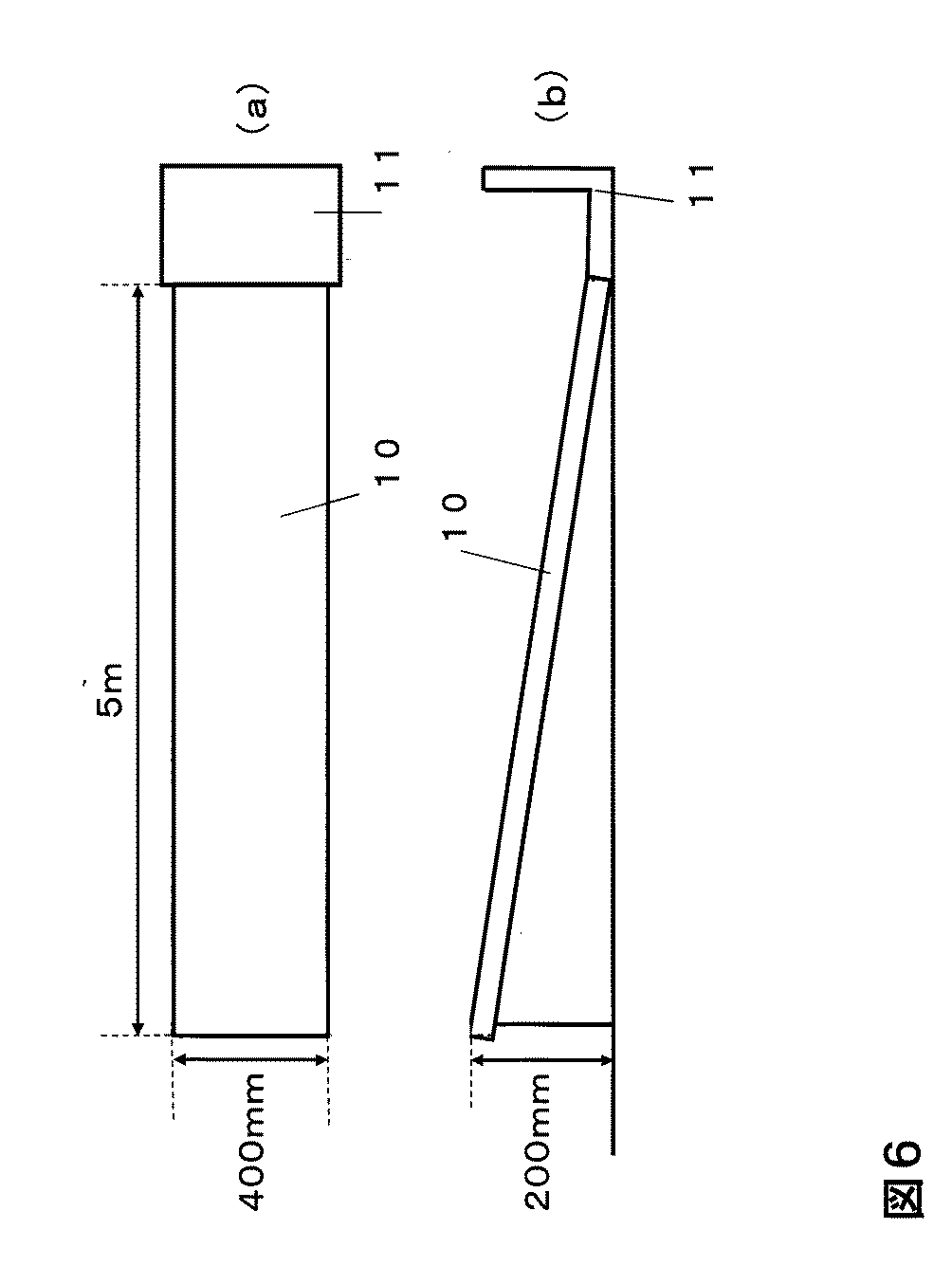
物流時の集配を想定し、図6に示すように、φ38スチールローラーコンベアとポータブルストッパー万能型1(いずれもトラスコ中山株式会社製)を用いて長さ5メートル、斜度4%の試験コースを作製した。コンベアの幅は400mmであった。梱包体をコースの上部から自重により流し、ストッパーにより受止めた後、梱包体の変形および破壊等の異常の有無を確認する作業を1サイクルとして繰返し、以下の基準で評価した。
◎:20サイクル後まで異常なし
〇:16サイクル〜20サイクルの間に異常発生
△:11サイクル〜15サイクルの間に異常発生
×:10サイクル以内に異常発生
(2) Assuming the collection and delivery during the transportation test logistics, as shown in FIG. 6, using a φ38 steel roller conveyor and a portable stopper universal type 1 (both manufactured by TRUSCO NAKAYAMA CORPORATION), a length of 5 meters and an inclination of 4 % Test courses were created. The conveyor width was 400 mm. After the package was poured from the top of the course by its own weight and received by the stopper, the operation of checking the presence or absence of abnormality such as deformation and destruction of the package was repeated as one cycle, and evaluated according to the following criteria.
◎: No abnormality until 20 cycles ○: Abnormality occurs between 16 and 20 cycles △: Abnormality occurs between 11 and 15 cycles ×: Abnormality occurs within 10 cycles
(3)引裂き開封試験
梱包体をミシン目を利用して引裂き開封した後、引裂き面を目視で観察し、以下の基準で評価した。
○:表層剥離がなく、また引裂き面の形状がミシン目に沿っていてきれいである。
△:表層剥離はないが、引裂き面の形状がきれいでない。
×:表層剥離がある。
(3) Tear-open test After tearing and opening the package using a perforation, the tear surface was visually observed and evaluated according to the following criteria.
○: No peeling of the surface layer, and the shape of the tear surface is clean along the perforation.
(Triangle | delta): There is no surface layer peeling, but the shape of a tear surface is not beautiful.
X: There is surface layer peeling.
比較例1
ミシン目を直線状にしたこと以外は実施例1と同様にして梱包体を用意し、試験を行った。結果を表1に示す。
Comparative Example 1
A package was prepared and tested in the same manner as in Example 1 except that the perforation was linear. The results are shown in Table 1.
比較例2
ミシン目を途切れることなく設けた(すなわちα=0)こと以外は実施例1と同様にして梱包体を用意し、試験を行った。結果を表1に示す。
Comparative Example 2
A package was prepared and tested in the same manner as in Example 1 except that the perforation was provided without interruption (that is, α = 0). The results are shown in Table 1.
比較例3
引裂帯の引裂き開始部(A)を、図7に示すように、側板のミシン目の長手方向の中央部分に設けたこと以外は実施例1と同様にして梱包体を用意し、試験を行った。結果を表1に示す。
Comparative Example 3
As shown in FIG. 7, a package was prepared and tested in the same manner as in Example 1 except that the tear strip start portion (A) was provided in the center portion in the longitudinal direction of the perforation of the side plate as shown in FIG. It was. The results are shown in Table 1.
本発明の段ボール箱は、十分な強度を有し、かつ引裂き後の引裂き面がきれいである。一方、ミシン目を直線状にした比較例1および、ミシン目を側板同士の連接部およびその近接部でも途切れることなく設けた比較例2では、強度が不十分であった。引裂帯の引裂き開始部の位置が本発明と異なる比較例3では、引裂き途中で引裂帯が千切れ、きれいに引裂くことができなかった。 The corrugated cardboard box of the present invention has sufficient strength and has a clean tear surface after tearing. On the other hand, the strength was insufficient in Comparative Example 1 in which the perforation was linear, and in Comparative Example 2 in which the perforation was provided without interruption even at the connecting portion between the side plates and its adjacent portion. In Comparative Example 3 in which the position of the tearing start portion of the tear band was different from that of the present invention, the tear band was broken during the tearing and could not be torn cleanly.
1:側板
2:側板
3:側板
4:側板
5:糊代用フラップ
6:蓋部フラップ
7:底部フラップ
8:ミシン目または罫線
9:引裂き面
10:ローラーコンベア
11:ストッパー
12:引裂帯
A:引裂き開始部
1: side plate 2: side plate 3: side plate 4: side plate 5: adhesive flap 6: lid flap 7: bottom flap 8: perforation or ruled line 9: tear surface 10: roller conveyor 11: stopper 12: tear band A: tear Starting part
Claims (1)
Priority Applications (1)
| Application Number | Priority Date | Filing Date | Title |
|---|---|---|---|
| JP2012014187A JP5894447B2 (en) | 2012-01-26 | 2012-01-26 | Cardboard box |
Applications Claiming Priority (1)
| Application Number | Priority Date | Filing Date | Title |
|---|---|---|---|
| JP2012014187A JP5894447B2 (en) | 2012-01-26 | 2012-01-26 | Cardboard box |
Publications (2)
| Publication Number | Publication Date |
|---|---|
| JP2013151315A true JP2013151315A (en) | 2013-08-08 |
| JP5894447B2 JP5894447B2 (en) | 2016-03-30 |
Family
ID=49048065
Family Applications (1)
| Application Number | Title | Priority Date | Filing Date |
|---|---|---|---|
| JP2012014187A Active JP5894447B2 (en) | 2012-01-26 | 2012-01-26 | Cardboard box |
Country Status (1)
| Country | Link |
|---|---|
| JP (1) | JP5894447B2 (en) |
Cited By (4)
| Publication number | Priority date | Publication date | Assignee | Title |
|---|---|---|---|---|
| JP2016068985A (en) * | 2014-09-29 | 2016-05-09 | 大王製紙株式会社 | Sanitary tissue paper housing box |
| JP2018118760A (en) * | 2017-01-26 | 2018-08-02 | 日本トーカンパッケージ株式会社 | Storage box |
| WO2018235789A1 (en) * | 2017-06-20 | 2018-12-27 | レンゴー株式会社 | Packaging box |
| CN109130308A (en) * | 2018-09-06 | 2019-01-04 | 深圳市绿尚设计顾问有限公司 | A kind of corrugated case and its production line and production technology |
Citations (5)
| Publication number | Priority date | Publication date | Assignee | Title |
|---|---|---|---|---|
| JP2006290376A (en) * | 2005-04-07 | 2006-10-26 | Rengo Co Ltd | Packaging bag with giveaway storage portion |
| GB2437514A (en) * | 2006-04-26 | 2007-10-31 | Sca Packaging Ltd | Display tray for supporting sachets |
| JP2008247477A (en) * | 2006-08-09 | 2008-10-16 | Rengo Co Ltd | Ribbed corrugated-fiberboard box |
| JP2010023885A (en) * | 2008-07-18 | 2010-02-04 | Kureha Corp | Packing box |
| JP2011235908A (en) * | 2010-05-06 | 2011-11-24 | Oji Chiyoda Container Kk | Corrugated fiberboard box with tear strip |
-
2012
- 2012-01-26 JP JP2012014187A patent/JP5894447B2/en active Active
Patent Citations (6)
| Publication number | Priority date | Publication date | Assignee | Title |
|---|---|---|---|---|
| JP2006290376A (en) * | 2005-04-07 | 2006-10-26 | Rengo Co Ltd | Packaging bag with giveaway storage portion |
| GB2437514A (en) * | 2006-04-26 | 2007-10-31 | Sca Packaging Ltd | Display tray for supporting sachets |
| JP2008247477A (en) * | 2006-08-09 | 2008-10-16 | Rengo Co Ltd | Ribbed corrugated-fiberboard box |
| JP2008280087A (en) * | 2006-08-09 | 2008-11-20 | Nippon Die Steel Kk | Punch die for ribbed cardboard box |
| JP2010023885A (en) * | 2008-07-18 | 2010-02-04 | Kureha Corp | Packing box |
| JP2011235908A (en) * | 2010-05-06 | 2011-11-24 | Oji Chiyoda Container Kk | Corrugated fiberboard box with tear strip |
Cited By (6)
| Publication number | Priority date | Publication date | Assignee | Title |
|---|---|---|---|---|
| JP2016068985A (en) * | 2014-09-29 | 2016-05-09 | 大王製紙株式会社 | Sanitary tissue paper housing box |
| JP2018118760A (en) * | 2017-01-26 | 2018-08-02 | 日本トーカンパッケージ株式会社 | Storage box |
| WO2018235789A1 (en) * | 2017-06-20 | 2018-12-27 | レンゴー株式会社 | Packaging box |
| JPWO2018235789A1 (en) * | 2017-06-20 | 2020-04-23 | レンゴー株式会社 | Packaging box |
| JP7221201B2 (en) | 2017-06-20 | 2023-02-13 | レンゴー株式会社 | packaging box |
| CN109130308A (en) * | 2018-09-06 | 2019-01-04 | 深圳市绿尚设计顾问有限公司 | A kind of corrugated case and its production line and production technology |
Also Published As
| Publication number | Publication date |
|---|---|
| JP5894447B2 (en) | 2016-03-30 |
Similar Documents
| Publication | Publication Date | Title |
|---|---|---|
| US4106615A (en) | Box blank and assembled package box for display | |
| US9469455B2 (en) | Discreet dual packaging | |
| JP6334737B2 (en) | Shell Freddy package with structural integrity and manufacturing process thereof | |
| JP5894447B2 (en) | Cardboard box | |
| JP2009214903A (en) | Packaging container | |
| US20190225365A1 (en) | Shipping and display container and method for forming the same | |
| JP2012091799A (en) | Packaging box | |
| CA2791586A1 (en) | Packaging bag for food | |
| CN113811493B (en) | Paper bag | |
| MX2011006879A (en) | Carton with reinforced corner. | |
| TWI481532B (en) | Package and carton with dispenser and blank therefor | |
| JP2005153959A (en) | Packaging bag of sanitary tissue paper | |
| JP3903389B2 (en) | Packing bag | |
| JP2011016571A (en) | Packaging box | |
| JP2003182767A (en) | Packaging structure and packaging method | |
| JP6491407B2 (en) | Package | |
| JP2003221068A (en) | Method for packing set of tissue paper packs for household paper | |
| CN205574471U (en) | Packaging device | |
| CN104443845A (en) | Fruit packaging strip | |
| JP3163927U (en) | Cardboard box | |
| CN214216480U (en) | Packing box | |
| JP3170785U (en) | Cardboard box | |
| US20140099047A1 (en) | Bag for food | |
| CN207618161U (en) | A kind of carton with special side cover structure | |
| JP6914797B2 (en) | Package |
Legal Events
| Date | Code | Title | Description |
|---|---|---|---|
| A621 | Written request for application examination |
Free format text: JAPANESE INTERMEDIATE CODE: A621 Effective date: 20141010 |
|
| A977 | Report on retrieval |
Free format text: JAPANESE INTERMEDIATE CODE: A971007 Effective date: 20150626 |
|
| A131 | Notification of reasons for refusal |
Free format text: JAPANESE INTERMEDIATE CODE: A131 Effective date: 20150702 |
|
| A521 | Request for written amendment filed |
Free format text: JAPANESE INTERMEDIATE CODE: A523 Effective date: 20150831 |
|
| TRDD | Decision of grant or rejection written | ||
| A01 | Written decision to grant a patent or to grant a registration (utility model) |
Free format text: JAPANESE INTERMEDIATE CODE: A01 Effective date: 20160218 |
|
| A61 | First payment of annual fees (during grant procedure) |
Free format text: JAPANESE INTERMEDIATE CODE: A61 Effective date: 20160226 |
|
| R150 | Certificate of patent or registration of utility model |
Ref document number: 5894447 Country of ref document: JP Free format text: JAPANESE INTERMEDIATE CODE: R150 |
|
| R250 | Receipt of annual fees |
Free format text: JAPANESE INTERMEDIATE CODE: R250 |
|
| R250 | Receipt of annual fees |
Free format text: JAPANESE INTERMEDIATE CODE: R250 |
|
| R250 | Receipt of annual fees |
Free format text: JAPANESE INTERMEDIATE CODE: R250 |