JP2013139059A - Single-edged gun drill - Google Patents
Single-edged gun drill Download PDFInfo
- Publication number
- JP2013139059A JP2013139059A JP2010096253A JP2010096253A JP2013139059A JP 2013139059 A JP2013139059 A JP 2013139059A JP 2010096253 A JP2010096253 A JP 2010096253A JP 2010096253 A JP2010096253 A JP 2010096253A JP 2013139059 A JP2013139059 A JP 2013139059A
- Authority
- JP
- Japan
- Prior art keywords
- opening
- flow passage
- clearance surface
- blade
- gun drill
- Prior art date
- Legal status (The legal status is an assumption and is not a legal conclusion. Google has not performed a legal analysis and makes no representation as to the accuracy of the status listed.)
- Withdrawn
Links
Images


Classifications
-
- B—PERFORMING OPERATIONS; TRANSPORTING
- B23—MACHINE TOOLS; METAL-WORKING NOT OTHERWISE PROVIDED FOR
- B23B—TURNING; BORING
- B23B51/00—Tools for drilling machines
- B23B51/06—Drills with lubricating or cooling equipment
-
- B—PERFORMING OPERATIONS; TRANSPORTING
- B23—MACHINE TOOLS; METAL-WORKING NOT OTHERWISE PROVIDED FOR
- B23B—TURNING; BORING
- B23B51/00—Tools for drilling machines
- B23B51/06—Drills with lubricating or cooling equipment
- B23B51/063—Deep hole drills, e.g. ejector drills
- B23B51/066—Gun drills
Landscapes
- Engineering & Computer Science (AREA)
- Mechanical Engineering (AREA)
- Drilling Tools (AREA)
Abstract
Description
本発明は工具本体内部にクーラントの流通路が形成された1枚刃ガンドリルに関する。 The present invention relates to a single blade gun drill in which a coolant flow passage is formed in a tool body.
小径の深穴加工を行う場合、一般的にガンドリルが使用され、ガンドリルの中でも特に1枚刃のガンドリルが多用される。1枚刃ガンドリルには、その後端部から供給されたクーラント(切削油)が先端部から噴射されるようにするために、内部に流通路が形成されているものも存在する(特許文献1参照)。クーラントがガンドリルの先端から噴射されると、切刃と穴底との間で生じる摩擦力が低減し、切刃も冷却される。またクーラントには生成された切りくずを加工穴の外へと排出する機能もある。 When drilling a small-diameter deep hole, a gun drill is generally used, and a single-edged gun drill is often used among gun drills. Some single-blade gun drills have a flow passage formed therein so that coolant (cutting oil) supplied from the rear end portion is injected from the front end portion (see Patent Document 1). ). When the coolant is sprayed from the tip of the gun drill, the frictional force generated between the cutting edge and the hole bottom is reduced, and the cutting edge is also cooled. The coolant also has a function of discharging the generated chips out of the machining hole.
上述したようなクーラントの効果のうち、切りくずの排出効果はガンドリルの側部に形成された切りくず排出溝を通過するクーラントの流量によって左右され、この流量が多いほど排出効果は高くなる。 Of the effects of the coolant as described above, the chip discharge effect depends on the flow rate of the coolant passing through the chip discharge groove formed on the side portion of the gun drill, and the higher the flow rate, the higher the discharge effect.
しかしながら、加工穴の内壁と切りくず排出溝との間に形成される空間は非常に狭く且つ長さが長いため、そこに生じる圧損は大きい。従って、現行のガンドリルは深穴加工に求められる切りくず排出能力を十分に満たしているとは決していえない状態にある。
この問題の一解決策として、クーラントの噴射口の面積を大きくするという方法が試みられているが、噴射口の面積を増大させることはガンドリルの先端部の強度低下につながるため、この方法は十分に有効なものとはなっていない。
However, since the space formed between the inner wall of the machining hole and the chip discharge groove is very narrow and long, the pressure loss generated there is large. Therefore, the current gun drill is in a state where it cannot be said that the chip discharging ability required for deep hole machining is sufficiently satisfied.
As a solution to this problem, a method of increasing the area of the coolant injection port has been attempted. However, increasing the area of the injection port leads to a decrease in strength of the tip of the gun drill. It is not effective.
またガンドリルには別の問題も存在している。それは、クーラントによる切刃の冷却効果に関してである。現行のガンドリルでは、深穴加工の際に求められている冷却機能を十分に発揮できないでいる。 Another problem exists with gun drills. It relates to the cooling effect of the cutting edge by the coolant. The current gun drill cannot fully perform the cooling function required for deep hole machining.
そこで本発明は上述した問題を鑑みて開発されたものである。すなわち、先端部の強度を低下させることなく、切りくず排出溝内を流れるクーラントの流量を増大させて切りくずの排出能力を向上させ、尚且つ切刃の冷却能力も向上させた1枚刃ガンドリルを提供することを目的とする。 The present invention has been developed in view of the above-described problems. That is, a single-blade gun drill that increases the flow rate of the coolant flowing in the chip discharge groove without increasing the strength of the tip, thereby improving the chip discharge capability and also improving the cooling capability of the cutting blade. The purpose is to provide.
本発明の1枚刃ガンドリルは上記課題を解決するために、先端部に略円形の第1開口部(第1噴射口)と略U字状の第2開口部(第2噴射口)とが形成され、第1開口部は中心刃の逃げ面である第1逃げ面に形成され、第2開口部は第1逃げ面に交差する第1クリアランス面と、この第1クリアランス面に交差する第2クリアランス面と、にまたがって形成されている。 In order to solve the above-described problems, the single-blade gun drill of the present invention has a substantially circular first opening (first injection port) and a substantially U-shaped second opening (second injection port) at the tip. The first opening is formed in a first flank that is a flank of the central blade, and the second opening is a first clearance surface that intersects the first flank and a first clearance that intersects the first clearance surface. It is formed across two clearance surfaces.
すなわち、本発明の1枚刃ガンドリルは略棒状の工具本体を備え、この工具本体の側面には切りくずを排出するための切りくず排出溝が形成され、前記工具本体の内部にはクーラントが流通するための流通路が形成され、前記工具本体の一方の先端部には切刃と、逃げ面と、すくい面と、第1クリアランス面と第2クリアランス面と、が形成され、前記第1クリアランス面と前記逃げ面とは、前記すくい面に直交し且つ前記工具本体の中心軸線を含む仮想的な平面上で交差し、前記第2クリアランス面は前記第1クリアランス面と交差し、且つ前記切りくず排出溝の壁面のうち前記すくい面として機能しない方の壁面とも交差し、前記流通路の噴射用の開口部は第1開口部と、略U字状の第2開口部と、の二つからなり、前記第1開口部は、前記逃げ面にのみ形成され、前記第2開口部は前記第1クリアランス面と前記第2クリアランス面とにまたがって形成され、且つ第2開口部のいずれの部分も前記第1クリアランス面および前記第2クリアランス面にのみ形成されている。 That is, the single-blade gun drill of the present invention has a substantially rod-shaped tool body, a chip discharge groove for discharging chips is formed on the side surface of the tool body, and coolant is circulated inside the tool body. And a cutting edge, a clearance surface, a rake surface, a first clearance surface, and a second clearance surface are formed at one tip of the tool body, and the first clearance The surface and the flank intersect each other on a virtual plane that is orthogonal to the rake surface and includes the center axis of the tool body, the second clearance surface intersects the first clearance surface, and the cutting surface. Crossing with the wall surface of the waste discharge groove which does not function as the rake face, the injection opening of the flow passage is a first opening and a substantially U-shaped second opening. The first opening comprises: The second opening is formed across the first clearance surface and the second clearance surface, and any part of the second opening is formed on the first clearance surface and the second clearance surface. 2 It is formed only on the clearance surface.
より好適には、上述した1枚刃ガンドリルであって、さらにその切刃が中心刃と外周刃とからなり、前記中心刃と前記外周刃とは180°よりも小さい角度で交差し、且つその交点が前記工具本体の中心軸線から外れた場所に位置し、前記中心刃に対して平行に見たときに、前記第2クリアランス面は前記すくい面に直交する面に対して30°〜45°の範囲で交差するように形成された1枚刃ガンドリルである。 More preferably, in the single-blade gun drill described above, the cutting edge further comprises a central blade and an outer peripheral blade, and the central blade and the outer peripheral blade intersect at an angle smaller than 180 °, and When the intersection is located at a location deviating from the central axis of the tool body and viewed in parallel to the central blade, the second clearance surface is 30 ° to 45 ° with respect to the surface perpendicular to the rake face. Is a one-blade gun drill formed so as to intersect with each other.
別の好適な発明としては、上述した1枚刃ガンドリルであって、さらに前記流通路が供給側の開口部とつながるシャンク部流通路と、該シャンク部流通路に連続して形成され且つ噴射用の開口部とつながるチップ部流通路と、からなり、前記シャンク部流通路が前記工具本体の断面のほぼ全体に亘って形成され、前記チップ部流通路が前記第1開口部につながる第1チップ部流通路と、前記第2開口部につながる第2チップ部流通路と、からり、前記第1チップ部流通路と前記第2チップ部流通路とが互いに交わらないように形成された1枚刃ガンドリルである。 Another preferred invention is the above-described single-blade gun drill, wherein the flow passage is further connected to the opening on the supply side, is formed continuously with the shank portion flow passage, and is used for injection. A chip part flow passage connected to the opening of the tool body, wherein the shank part flow path is formed over substantially the entire cross section of the tool body, and the chip part flow path is connected to the first opening. One sheet formed so that the first chip part flow path and the second chip part flow path do not cross each other from the partial flow path and the second tip part flow path connected to the second opening It is a blade gun drill.
別の好適な発明としては、上述した1枚刃ガンドリルであって、さらに前記第1チップ部流通路の開口部のうち前記シャンク部流通路につながる方の開口部が、前記シャンク部流通路の開口部の内側に形成され、前記第2チップ部流通路の開口部のうち前記シャンク部流通路につながる方の開口部が、前記シャンク部流通路の開口部の内側に形成された1枚刃ガンドリルである。 As another preferred invention, in the single-blade gun drill described above, an opening portion of the opening portion of the first tip portion flow passage which is connected to the shank portion flow passage is further provided in the shank portion flow passage. One blade formed on the inner side of the opening portion of the shank portion flow passage, wherein the opening portion formed on the inner side of the opening portion and connected to the shank portion flow passage among the opening portions of the second tip portion flow passage is formed A gun drill.
本発明の1枚刃ガンドリルによれば、従来の1枚刃ガンドリルと比べて切りくず排出溝を通過するクーラントの流量が大きいので、切りくず排出能力が高い。切りくずが加工穴外へスムーズに排出されることで、ドリルが切りくずを噛み込んだり、切りくずが加工穴の内壁を傷つけたりすることが少なくなる。 According to the single blade gun drill of the present invention, the flow rate of the coolant passing through the chip discharge groove is larger than that of the conventional single blade gun drill, so that the chip discharge capability is high. Since the chips are smoothly discharged out of the machining hole, the drill does not bite the chips or the chips are less likely to damage the inner wall of the machining hole.
また、本発明の1枚刃ガンドリルによれば、従来のガンドリルよりも切刃に対してクーラントが効率よく噴射されるので、切刃の冷却能力が高くなっている。、 Further, according to the single blade gun drill of the present invention, the coolant is injected more efficiently to the cutting blade than the conventional gun drill, so the cooling ability of the cutting blade is high. ,
本発明の1枚刃ガンドリルは切りくずの排出能力および切刃の冷却能力が、従来よりも向上しているにもかかわらず、先端部の強度の低下が最小限に抑えられており、一般的な穴加工に十分対応できるものとなっている。 Although the single-blade gun drill of the present invention has improved chip discharging ability and cutting edge cooling ability compared with the conventional one, the decrease in strength at the tip is minimized, It can be used for drilling holes.
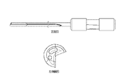
図1は本実施形態の1枚刃ガンドリルの正面図および断面図である。
図2は本実施形態の1枚刃ガンドリルの先端部を示す側面図である。
図3は図1のC−C断面図である。
FIG. 1 is a front view and a cross-sectional view of a single blade gun drill of this embodiment.
FIG. 2 is a side view showing the tip of the single-blade gun drill of the present embodiment.
3 is a cross-sectional view taken along the line CC of FIG.
[構造]
図1〜図3に示すように、本実施形態の1枚刃ガンドリルDは工具本体1と、ドライバ2とを備え、ドライバ2は工具本体1の一方の端部に取り付けられる。ドライバ2はガンドリルDを工作機械に取り付ける際の把持部として機能する。
工具本体1は略棒状であり、その側面にはV字状の切りくず排出溝3が1条形成されている。切りくず排出溝3は工具本体1の先端から後端にかけて直線的に形成される。生成された切りくずは切りくず排出溝3内を流れるクーラントによって押し流され、加工穴外へと排出される。
[Construction]
As shown in FIGS. 1 to 3, the single-blade gun drill D of this embodiment includes a
The
図1の断面図が示すように、工具本体1の内部にはクーラントが流通するための流通路が形成されており、その流通路はシャンク部流通路4aとチップ部流通路4bとの二つの部分で構成されている。
シャンク部流通路4aは工具本体1のドライバ2が設けられた側の端部に形成されたクーラントの供給口(供給側開口部)とつながる流通路であって、流通路全体の半分以上を占める。図1においては、S1で示された箇所がシャンク部流通路4aが形成された部分である。シャンク部流通路4aは図1に示すように、工具本体1の断面形状に沿ってほぼ全体に亘って形成されている。クーラントの流量を増加させるためには、工具本体1のねじり剛性が過度に損なわれない範囲で、限界まで大きくシャンク部流通路4aを形成することが好ましい。
As shown in the cross-sectional view of FIG. 1, a flow passage for circulating coolant is formed inside the
The shank
チップ部流通路4bはシャンク部流通路4aに連続して形成され、工具本体1の先端部に形成されたクーラントの噴射口(噴射側開口部)につながっている。図1においては、S2で示された箇所にチップ部流通路4bが形成されている。
チップ部流通路4bは略円形状の第1開口部につながる第1チップ部流通路4b1と、略U字状の第2開口部につながる第2チップ部流通路4b2と、からなる。第1チップ部流通路4b1と第2チップ部流通路4b2とは互いに交差することなく、工具本体1の中心軸線に沿ってほぼ平行に延びて形成されている。
The tip
The tip
図2に示すように、工具本体1の先端には、すくい面5と、逃げ面6と、切刃7と、クリアランス面8と、が形成されている。
本実施形態の1枚刃ガンドリルDにおいては、切りくず排出溝3の一方の溝壁の端部がすくい面5として機能し、生成された切りくずはすくい面5によって丸められ、適当な長さで切断される。
As shown in FIG. 2, a
In the single blade gun drill D of the present embodiment, the end of one groove wall of the
逃げ面6は第1逃げ面6aと第2逃げ面6bとからなり、両逃げ面とすくい面5との交差稜線部には切刃7が形成される。特に、第1逃げ面6aとすくい面5との交差稜線部に形成される切刃は、加工穴の中心部を切削する中心刃7aとして機能し、第2逃げ面6bとすくい面5との交差稜線部に形成される切刃は、加工穴の外周部分を切削する外周刃7bとして機能する。
The flank 6 includes a
図1に示すように、第1逃げ面6aは第2逃げ面6bと鋭角に交差し、その交差部が工具本体1の最も先端になるように、工具本体1のもう一方の端部側に向かって傾斜して形成されている。すなわち、このことを図2を用いて説明すると、第1逃げ面6aは第2逃げ面6bとの交差部を基点に紙面奥側に向かって傾斜している。第1逃げ面6aがこのように形成されることで、加工穴底と第1逃げ面6aとの間で空間が確保される。
第1逃げ面6aと同様に、第2逃げ面6bも第1逃げ面6aとの交差部を基点に紙面奥側に向かって傾斜して形成されている。
As shown in FIG. 1, the
Similar to the
クリアランス面8は第1クリアランス面8aと第2クリアランス面8bとからなる。
第1クリアランス面8aと第1逃げ面6aとは、すくい面5に直交し且つ工具本体の中心軸線CLを含む仮想平面F上で、180°で交差している。すなわち、第1クリアランス面8aは第1逃げ面6aの延長面上に形成され、この二つの面は同一平面上に乗っている。
The
The
第2クリアランス面8bは第1クリアランス面8aと鈍角に交差する平面であって、切りくず排出溝3の壁面のうちすくい面として機能しない方の壁面とも交差している。また別の言い方をすると、第2クリアランス面8bは第1クリアランス面8aとの交差部からヒール側に向かって傾斜して形成された平面である。
The
工具本体1の先端の縁の部分には面取り加工が施されている。縁に面取り加工が施されることで、その部分が欠け難くなる。
The edge portion at the tip of the
本実施形態1枚刃ガンドリルDにおいては、クーラントの噴射口である第1開口部および第2開口部の形状と形成箇所とが発明の本質的な要素となっている。
すなわち図2に示すように、1枚刃ガンドリルDにおいて、第1開口部9aは略円形に形成され、且つ第1逃げ面6aの内側にのみに形成される。別の表現を用いれば、略円形状の第1開口部9aは、第1逃げ面6aに隣接する第1クリアランス面8a側にはみ出すことなく、全ての部分が第1逃げ面6a内に収まるように形成される、ということである。
In the single-blade gun drill D according to the present embodiment, the shapes and locations of the first opening and the second opening, which are coolant injection ports, are essential elements of the invention.
That is, as shown in FIG. 2, in the single blade gun drill D, the
第2開口部9bは楕円の中央部分の片側だけが中心に向かって凹んだような略U字状の形状になっている。そして、第2開口部9bは第1クリアランス面8aおよび第2クリアランス面8bにまたがって、且つ第2開口部9bの一方端部は第1逃げ面6aへはみ出さないように形成されている。
The
図3は図1のC−C断面図である。図3に示すように、本実施形態のガンドリルDにおいては、シャンク部流通路4aとチップ部流通路4bとは、チップ部流通路4bの供給口側の開口部がシャンク部流通路4aの噴射口側の開口部の内側に含まれるように接続している。このような位置関係でシャンク部流通路4aとチップ部流通路4bとが設計されると、クーラントがシャンク部流通路4aからチップ部流通路4bへと移動するときに生じる圧損が最小限に抑えられる。
3 is a cross-sectional view taken along the line CC of FIG. As shown in FIG. 3, in the gun drill D of the present embodiment, the shank
本実施形態の1枚刃ガンドリルDでは、第2開口部9bの一部が第2クリアランス面8bへ伸びて形成されているため、切りくず排出溝3を流れるクーラントのエネルギーの損失が最小限になる。
In the single blade gun drill D of the present embodiment, since a part of the
すなわち、従来のガンドリルでは噴射口から噴射されたクーラントは一度、加工穴の穴底へ衝突してから切りくず排出溝へと流入していた。そのため、クーラントが加工穴の底に衝突した際に、クーラントが持っていたエネルギーの一部が失われ、結果として切りくず排出溝内を通過するクーラントの流量が低下していた。 That is, in the conventional gun drill, the coolant injected from the injection port once collides with the bottom of the machining hole and then flows into the chip discharge groove. Therefore, when the coolant collided with the bottom of the machining hole, a part of the energy that the coolant had was lost, and as a result, the flow rate of the coolant passing through the chip discharge groove was reduced.
しかしながら、本実施形態の1枚刃ガンドリルDにおいては、クリアランス面8にも開口部(噴射口)が形成されているため、そこから噴射されたクーラントは加工穴底に衝突することなく、直接切りくず排出溝3に流入する。そのため、衝突によるエネルギーの損失が抑制され、従来よりも大きい流量でクーラントは切りくず排出溝3を流れる。
However, in the single-blade gun drill D of this embodiment, since the opening (injection port) is also formed in the
さらに、第2クリアランス面8bに第2開口部9bの一部を伸ばして形成することにより、クーラントの冷却効果が高まる。すなわち、従来の噴射方法の場合、クーラントが一旦加工穴底に衝突するため、衝突の際にクーラントが高温になった加工穴底から熱を受け取り、切刃を冷却する以前にすでにクーラントの温度が上昇してしまう。
Furthermore, the cooling effect of the coolant is enhanced by forming a part of the
しかしながら、本実施形態の1枚刃ガンドリルDにおいては、第2クリアランス面8bに形成された第2開口部9bから噴射されたクーラントが、切刃7に対して切りくず排出溝3側から直接的に付与されるので、クーラントの温度上昇が抑制され、クーラントの冷却効果が高くなる。
However, in the single blade gun drill D of the present embodiment, the coolant sprayed from the
また、第1開口部9aが第1逃げ面6aに形成されることで、ここから噴射されたクーラントは、切刃7を挟んで第2開口部9bとは反対側から切刃7に対して直接付与される。
Further, since the
このように、クーラントが切刃7に対して異なる二つの方向から直接付与されることで、本実施形態の1枚刃ガンドリルDの切刃7は従来のガンドリルよりも温度が上昇しにくくなる。
Thus, the coolant is directly applied to the
第2開口部9bの形成箇所を第1クリアランス面8aおよび第2クリアランス面8bにのみ形成し、且つ第1開口部9aの形成箇所を第1逃げ面6a内のみとすることで、第2開口部9bの端部であって第1逃げ面6aに近い方の端部と、第1開口部9aと、の間に肉厚が確保される。このことにより、1枚刃ガンドリルDは通常の切削条件での切削に適用可能な程度の剛性を持つことができる。
The
図4はクリアランス面の傾斜角度を説明するための説明図である。図4に示すように、中心刃7aに平行に、すなわち中心刃7aなりに第2クリアランス面8bを見たときに、すくい面5に直交する面に対して30°〜45°の範囲で交差するように形成されることが好ましい。すなわち、図4のθの角度が30°〜45°であると、クーラントがより効果的に切りくず排出溝3へと噴射される。
FIG. 4 is an explanatory diagram for explaining the inclination angle of the clearance surface. As shown in FIG. 4, when the
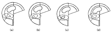
本発明の1枚刃ガンドリルは上述した実施形態だけでなく、他にも様々なものがある。
例えば、図5に示すように、第1開口部の形状が三角形((a)参照)、角が丸まった略三角形((b)参照)、半円((c)参照)、弓形((d)参照)等の形状が可能である。すなわち、第1逃げ面内にのみ形成される限り、第1開口部はどのような形状であっても構わない。また当然、第1開口部の面積が大きいほどクーラントの流量は増加する。
The single-blade gun drill of the present invention is not limited to the above-described embodiment, but includes various other types.
For example, as shown in FIG. 5, the first opening has a triangular shape (see (a)), a substantially triangular shape with rounded corners (see (b)), a semicircle (see (c)), and an arcuate shape ((d ))) Is possible. That is, as long as it is formed only in the first flank, the first opening may have any shape. Naturally, the flow rate of the coolant increases as the area of the first opening increases.
また別の実施形態として、チップ部流通路4bの一部がシャンク部流通路4aの外側へはみ出して形成されたものも可能である。すなわち、図6に示すように、チップ部流通路4b1、4b2の開口部の一部が、シャンク部流通路4aの開口部の外側へはみ出るように、互いを接続させることも可能である。この場合当然、開口部9a、9bの一部もシャンク部流通路4aの延長線からはみ出して形成されることになる。
ただしこの場合、従来の1枚刃ガンドリルよりはクーラントの流量は増加するが、上述した実施形態よりはクーラントの流量は低下する。
In another embodiment, a part of the tip
However, in this case, the flow rate of the coolant is increased as compared with the conventional single blade gun drill, but the flow rate of the coolant is decreased as compared with the above-described embodiment.
また、本実施形態では第1逃げ面6aと第1クリアランス面8aとは180°で交差しているが、これら二つの面は180°よりも小さい角度で交差するように形成されてもよい。すなわち、第1クリアランス面8aを第1逃げ面6aと鈍角に交差させ、第1クリアランス面8aと加工穴底との間の空間をより大きく確保するようにしても良い。
In the present embodiment, the
[実施例]
次に、本発明の実施例のガンドリルと、比較例のガンドリルとを比較実験した結果を以下に示す。なお、実施例および比較例の形状を図7A〜図7Eに示す。
なお、実施例2ではチップ部流通路の縁の部分がシャンク部流通路の外側にはみ出して形成されている。
また、比較例1では第1クリアランス面と第2クリアランス面とにまたがって形成された開口部が、実施例1のような略U字状ではなく、円形に形成されている。
また、比較例2では実施例1の第2開口部と同じ形状の開口部が、第1逃げ面と第1クリアランス面とにまたがって形成されている。
また、比較例3では実施例1と同じ形状の第2開口部が実施例1と同じ箇所に形成されているが、実施例1の第1開口部と同じ形状の円形の開口部が第1逃げ面と第1クリアンス面とにまたがって形成されている。
[Example]
Next, the results of comparative experiments of the gun drill of the example of the present invention and the gun drill of the comparative example are shown below. In addition, the shape of an Example and a comparative example is shown to FIG. 7A-FIG. 7E.
In Example 2, the edge portion of the tip portion flow passage is formed so as to protrude outside the shank portion flow passage.
In Comparative Example 1, the opening formed across the first clearance surface and the second clearance surface is formed in a circular shape instead of the substantially U shape as in the first embodiment.
In Comparative Example 2, an opening having the same shape as the second opening of Example 1 is formed across the first clearance surface and the first clearance surface.
In Comparative Example 3, the second opening having the same shape as in Example 1 is formed at the same location as in Example 1. However, the circular opening having the same shape as the first opening in Example 1 is the first. It is formed across the flank and the first clearance surface.
以下に実施例1〜比較例3までの緒元を示す。
(緒元)
実施例1(図7A参照):直径 6mm
クーラントの供給圧力 5MPa
第1開口部の面積 0.665mm2
第2開口部の面積 2.015mm2
先端から後端までの長さ 200mm
材質 超硬合金
実施例2(図7B参照):直径 6mm
クーラントの供給圧力 5MPa
第1開口部の面積 0.665mm2
第2開口部の面積 2.015mm2
先端から後端までの長さ 200mm
材質 超硬合金
比較例1(図7C参照):直径 6mm
クーラントの供給圧力 5MPa
開口部の総面積(二つの合計)2.27mm2
先端から後端までの長さ 200mm
材質 超硬合金
比較例2(図7D参照):直径 6mm
クーラントの供給圧 5MPa
開口部の面積 2.934mm2
先端から後端までの長さ 200mm
材質 超硬合金
比較例3(図7E参照):直径 6mm
クーラントの供給圧 5MPa
略円形開口部の面積 0.665mm2
略U字状開口部の面積 2.015mm2
先端から後端までの長さ 200mm
材質 超硬合金
The specifications from Example 1 to Comparative Example 3 are shown below.
(Omoto)
Example 1 (see FIG. 7A): Diameter 6 mm
Area of the first opening 0.665mm 2
Area of second opening 2.015mm 2
Length from the front end to the rear end 200mm
Material Cemented carbide
Example 2 (see FIG. 7B): Diameter 6 mm
Area of the first opening 0.665mm 2
Area of second opening 2.015mm 2
Length from the front end to the rear end 200mm
Material Cemented carbide
Comparative Example 1 (see FIG. 7C): Diameter 6 mm
Total area of the opening (total of the two) 2.27mm 2
Length from the front end to the rear end 200mm
Material Cemented carbide
Comparative Example 2 (see FIG. 7D): Diameter 6 mm
Area of opening 2.934 mm 2
Length from the front end to the rear end 200mm
Material Cemented carbide
Comparative Example 3 (see FIG. 7E): Diameter 6 mm
Area of substantially circular opening 0.665mm 2
Area of substantially U-shaped opening 2.015mm 2
Length from the front end to the rear end 200mm
Material Cemented carbide
(流量に関する実験)
穴径6.05mm、深さ100mmの鉛直上向きに開口した穴に各ガンドリルを挿入し、その後それぞれの1枚刃ガンドリルにクーラントを供給する。5分間クーラントを供給し、その間に穴から溢れ出たクーラントの量を測定する。測定したクーラントの量をクーラントの供給時間で除して流量を算出する。この実験を5回繰り返し、その平均の値を表1に載せた。
(Experiment regarding flow rate)
Each gun drill is inserted into a vertically open hole having a hole diameter of 6.05 mm and a depth of 100 mm, and then coolant is supplied to each single-blade gun drill. Supply the coolant for 5 minutes and measure the amount of coolant that has overflowed from the holes during that time. The flow rate is calculated by dividing the measured coolant amount by the coolant supply time. This experiment was repeated 5 times, and the average value was listed in Table 1.
(ねじり剛性に関する実験)
各ガンドリルの先端から30mmの位置を固定して1N/mのトルクを加えたときに発生する最大主応力の値をコンピュータ解析で算出した。
算出された最大主応力から、実施例1のねじり剛性に対する他の1枚刃ガンドリルのねじり剛性の比を算出するために、実施例1の最大主応力を実施例2および比較例の最大主応力で除し、その結果を表1に載せた。
(Experiment on torsional rigidity)
The value of the maximum principal stress generated when a torque of 1 N / m was applied while fixing a position 30 mm from the tip of each gun drill was calculated by computer analysis.
In order to calculate the ratio of the torsional rigidity of the other single-blade gun drill to the torsional rigidity of Example 1 from the calculated maximum main stress, the maximum main stress of Example 1 and the maximum main stress of Example 2 are compared. The results are shown in Table 1.
(切刃部の温度に関する実験)
各1枚刃ガンドリルを用いて、S45Cの立方体ブロックに深さ100mmの穴を切削速度120m/分で加工し、加工終了後の切刃の温度を測定する。この実験を5回行い、その平均値を表1に載せた。

Using each single-blade gun drill, a hole with a depth of 100 mm is machined into a S45C cubic block at a cutting speed of 120 m / min, and the temperature of the cutting blade after machining is measured. This experiment was performed 5 times, and the average value was listed in Table 1.
表1に示すように、実施例1と比較例1とを比べた場合、比較例1の開口部の面積は実施例1の85%であるのに対して、流量は実施例1の79%となっている。このことは、実施例1のクーラントの噴射性能が単純な開口面積の増加による流量増加の程度を超えて向上していることを示している。 As shown in Table 1, when Example 1 and Comparative Example 1 are compared, the area of the opening of Comparative Example 1 is 85% of Example 1, whereas the flow rate is 79% of Example 1. It has become. This indicates that the injection performance of the coolant of Example 1 has improved beyond the degree of increase in flow rate due to a simple increase in the opening area.
また、実施例1と比較例2とを比べた場合、比較例1は実施例1よりも開口部の面積が約9%程大きいにもかかわらず、その流量は実施例1の84%に留まっている。このことは、実施例1のように略U字形状の第2開口部の一部がクリアランス面に形成されること、および第1逃げ面に第1開口部が形成されることが、相乗効果を生み出して噴射性能を向上させることを示している。 Further, when Example 1 is compared with Comparative Example 2, the flow rate of Comparative Example 1 is only 84% of Example 1 although the area of the opening is about 9% larger than Example 1. ing. This is because a part of the substantially U-shaped second opening is formed on the clearance surface as in the first embodiment, and the first opening is formed on the first flank. To improve the injection performance.
各1枚刃ガンドリル切刃温度に関しても、表1に示すように実施例1の切刃の温度が最も低くなっており、実施例1の冷却性能の高さが示された。 Regarding each single-blade gun drill cutting edge temperature, as shown in Table 1, the temperature of the cutting edge of Example 1 was the lowest, indicating the high cooling performance of Example 1.
実施例1のねじれ剛性は比較例1よりも僅かに大きく、比較例2よりも小さいが、実用上問題ない大きさのねじれ剛性を有する比較例1よりも大きいことから、実施例1のねじれ剛性は十分な大きさを有しているということが示された。 The torsional rigidity of Example 1 is slightly larger than that of Comparative Example 1 and smaller than that of Comparative Example 2. However, the torsional rigidity of Example 1 is larger than that of Comparative Example 1 having a torsional rigidity having a practically no problem. Has been shown to have a sufficient size.
本発明の1枚刃ガンドリルは従来の1枚刃ガンドリルよりも切りくず排出能力が高いので、加工中に切りくずが詰まったり切りくずによって加工穴の内壁が傷付いたりすることが防止される。 Since the single-blade gun drill of the present invention has a higher chip discharge capability than the conventional single-blade gun drill, it is possible to prevent the chips from becoming clogged during processing and from damaging the inner wall of the processing hole.
D…一枚刃ガンドリル
1…工具本体
2…ドライバ
3…切りくず排出溝
4a…シャンク部流通路
4b…チップ部流通路
4b1…第1チップ部流通路
4b2…第2チップ部流通路
5…すくい面
6…逃げ面
6a…第1逃げ面
6b…第2逃げ面
7…切刃
7a…中心刃
7b…外周刃
8…クリアランス面
8a…第1クリアランス面
8b…第2クリアランス面
9a…第1開口部
9b…第2開口部
D ... Single-
Claims (4)
1)略棒状の工具本体を備える。
2)前記工具本体の側面には切りくずを排出するための切りくず排出溝が形成されている。
3)前記工具本体の内部にはクーラントが流通するための流通路が形成されている
4)前記工具本体の一方の先端部には切刃と、逃げ面と、すくい面と、第1クリアランス面と第2クリアランス面と、が形成されている。
5)前記第1クリアランス面と前記逃げ面とは、前記すくい面に直交し且つ前記工具本体の中心軸線を含む仮想的な平面上で交差している。
6)前記第2クリアランス面は前記第1クリアランス面と交差し、且つ前記切りくず排出溝の壁面のうち前記すくい面として機能しない方の壁面とも交差している。
7)前記流通路の噴射側の開口部は第1開口部と、略U字状の第2開口部と、の二つからなる。
8)前記第1開口部は、前記逃げ面にのみ形成されている。
9)前記第2開口部は前記第1クリアランス面と前記第2クリアランス面とにまたがって形成され、且つ第2開口部のいずれの部分も前記第1クリアランス面および前記第2クリアランス面にのみ形成されている。 A single-blade gun drill having the following components.
1) A substantially rod-shaped tool body is provided.
2) A chip discharge groove for discharging chips is formed on the side surface of the tool body.
3) A flow passage for circulating coolant is formed inside the tool body. 4) A cutting edge, a flank surface, a rake surface, and a first clearance surface at one end of the tool body. And a second clearance surface are formed.
5) The first clearance surface and the flank surface intersect with each other on a virtual plane that is orthogonal to the rake surface and includes the central axis of the tool body.
6) The second clearance surface intersects the first clearance surface, and also intersects one of the wall surfaces of the chip discharge groove that does not function as the rake surface.
7) The opening on the injection side of the flow passage is composed of a first opening and a substantially U-shaped second opening.
8) The first opening is formed only on the flank.
9) The second opening is formed across the first clearance surface and the second clearance surface, and any part of the second opening is formed only on the first clearance surface and the second clearance surface. Has been.
1)前記切刃は中心刃と外周刃とからなる。
2)前記中心刃と前記外周刃とは180°よりも小さい角度で交差し、且つその交点は前記工具本体の中心軸線から外れた場所に位置する。
3)前記中心刃に対して平行に見たときに、前記第2クリアランス面は前記すくい面に直交する面に対して30°〜45°の範囲で交差するように形成されている。 The single-blade gun drill according to claim 1, further comprising the following constituent elements: 1) The cutting edge comprises a central blade and an outer peripheral blade.
2) The central blade and the outer peripheral blade intersect with each other at an angle smaller than 180 °, and the intersection is located at a location deviating from the central axis of the tool body.
3) When viewed in parallel to the central blade, the second clearance surface is formed so as to intersect within a range of 30 ° to 45 ° with respect to a surface orthogonal to the rake surface.
1)前記流通路は、供給側の開口部とつながるシャンク部流通路と、該シャンク部流通路に連続して形成され且つ噴射側の開口部とつながるチップ部流通路と、からなる。
2)前記シャンク部流通路は前記工具本体の断面のほぼ全体に亘って形成されている。
3)前記チップ部流通路は前記第1開口部につながる第1チップ部流通路と、前記第2開口部につながる第2チップ部流通路と、からなる。
4)前記第1チップ部流通路と前記第2チップ部流通路とは互いに交わらないように形成されている。 The single blade gun drill according to claim 1, further comprising the following constituent elements: the flow passage is formed continuously with the shank portion flow passage connected to the opening on the supply side, the shank portion flow passage, and the injection A tip portion flow passage connected to the opening on the side.
2) The shank portion flow passage is formed over substantially the entire cross section of the tool body.
3) The tip part flow path includes a first tip part flow path connected to the first opening and a second tip part flow path connected to the second opening.
4) The first tip portion flow passage and the second tip portion flow passage are formed so as not to cross each other.
1)前記第1チップ部流通路の開口部のうち前記シャンク部流通路につながる方の開口部は、前記シャンク部流通路の開口部の内側に形成されている。
2)前記第2チップ部流通路の開口部のうち前記シャンク部流通路につながる方の開口部は、前記シャンク部流通路の開口部の内側に形成されている。 The single blade gun drill according to claim 3, further comprising the following constituent elements.
1) The opening connected to the shank portion flow passage among the openings of the first tip portion flow passage is formed inside the opening of the shank portion flow passage.
2) Of the openings of the second tip part flow passage, the opening connected to the shank part flow passage is formed inside the opening of the shank part flow passage.
Priority Applications (2)
| Application Number | Priority Date | Filing Date | Title |
|---|---|---|---|
| JP2010096253A JP2013139059A (en) | 2010-04-19 | 2010-04-19 | Single-edged gun drill |
| PCT/JP2011/059662 WO2011132686A1 (en) | 2010-04-19 | 2011-04-19 | Gun drill |
Applications Claiming Priority (1)
| Application Number | Priority Date | Filing Date | Title |
|---|---|---|---|
| JP2010096253A JP2013139059A (en) | 2010-04-19 | 2010-04-19 | Single-edged gun drill |
Publications (1)
| Publication Number | Publication Date |
|---|---|
| JP2013139059A true JP2013139059A (en) | 2013-07-18 |
Family
ID=44834203
Family Applications (1)
| Application Number | Title | Priority Date | Filing Date |
|---|---|---|---|
| JP2010096253A Withdrawn JP2013139059A (en) | 2010-04-19 | 2010-04-19 | Single-edged gun drill |
Country Status (2)
| Country | Link |
|---|---|
| JP (1) | JP2013139059A (en) |
| WO (1) | WO2011132686A1 (en) |
Cited By (3)
| Publication number | Priority date | Publication date | Assignee | Title |
|---|---|---|---|---|
| JP2018099774A (en) * | 2018-03-29 | 2018-06-28 | みやび建設株式会社 | Drill attachment jig, drill device formation mechanism, and drill device |
| CN114083001A (en) * | 2021-10-20 | 2022-02-25 | 厦门金鹭特种合金有限公司 | Laminated material thin plate hole machining tool |
| JP7544300B1 (en) | 2024-02-06 | 2024-09-03 | 株式会社タンガロイ | Body and cutting tools |
Families Citing this family (8)
| Publication number | Priority date | Publication date | Assignee | Title |
|---|---|---|---|---|
| DE102012016660A1 (en) * | 2012-08-24 | 2014-02-27 | Botek Präzisionsbohrtechnik Gmbh | gun drills |
| EP2952278B1 (en) * | 2013-01-29 | 2020-03-11 | OSG Corporation | Drill |
| DE102013205056A1 (en) | 2013-03-21 | 2014-09-25 | Gühring KG | Multi-bladed drilling tool with internal cooling channels |
| WO2014155527A1 (en) * | 2013-03-26 | 2014-10-02 | オーエスジー株式会社 | Three-bladed drill with cutting fluid supply hole |
| DE202015001069U1 (en) * | 2015-02-13 | 2016-05-17 | Botek Präzisionsbohrtechnik Gmbh | Single-fluted gun drills |
| CN105904004A (en) * | 2016-06-23 | 2016-08-31 | 重村钢模机械工业(苏州)有限公司 | Gun drill |
| CN106964802A (en) * | 2017-05-09 | 2017-07-21 | 山西平阳重工机械有限责任公司 | Small-deep Hole expanding method and its cutter |
| US10814406B1 (en) * | 2019-04-24 | 2020-10-27 | Raytheon Technologies Corporation | Internal cooling passages for rotating cutting tools |
Family Cites Families (5)
| Publication number | Priority date | Publication date | Assignee | Title |
|---|---|---|---|---|
| JPS52136488A (en) * | 1976-05-10 | 1977-11-15 | Sumitomo Electric Ind Ltd | Gun drill |
| JPS5541285U (en) * | 1978-09-11 | 1980-03-17 | ||
| JP2003165010A (en) * | 2001-11-29 | 2003-06-10 | Toshiba Tungaloy Co Ltd | Solid gun drill |
| US7195428B2 (en) * | 2002-11-11 | 2007-03-27 | Ford Global Technologies, Llc | Gundrill |
| JP4529383B2 (en) * | 2003-06-13 | 2010-08-25 | 三菱マテリアル株式会社 | Drill |
-
2010
- 2010-04-19 JP JP2010096253A patent/JP2013139059A/en not_active Withdrawn
-
2011
- 2011-04-19 WO PCT/JP2011/059662 patent/WO2011132686A1/en active Application Filing
Cited By (4)
| Publication number | Priority date | Publication date | Assignee | Title |
|---|---|---|---|---|
| JP2018099774A (en) * | 2018-03-29 | 2018-06-28 | みやび建設株式会社 | Drill attachment jig, drill device formation mechanism, and drill device |
| CN114083001A (en) * | 2021-10-20 | 2022-02-25 | 厦门金鹭特种合金有限公司 | Laminated material thin plate hole machining tool |
| CN114083001B (en) * | 2021-10-20 | 2022-12-30 | 厦门金鹭特种合金有限公司 | Laminated material thin plate hole machining tool |
| JP7544300B1 (en) | 2024-02-06 | 2024-09-03 | 株式会社タンガロイ | Body and cutting tools |
Also Published As
| Publication number | Publication date |
|---|---|
| WO2011132686A1 (en) | 2011-10-27 |
Similar Documents
| Publication | Publication Date | Title |
|---|---|---|
| JP2013139059A (en) | Single-edged gun drill | |
| JP4802095B2 (en) | Drill | |
| KR101701543B1 (en) | Cutting insert and rotary cutting tool | |
| JP5447129B2 (en) | Drill with coolant hole | |
| JP5951113B2 (en) | 3-flute drill with cutting fluid supply hole | |
| EP3513892B1 (en) | Cutting tool | |
| JP4919527B1 (en) | Drill | |
| JP2007307642A (en) | Drill | |
| US20140056656A1 (en) | Turning tool for internal machining | |
| JP2009018360A (en) | Drill for metal working | |
| JP2010094748A (en) | Cutting tool | |
| JP2018114589A (en) | drill | |
| JP4627849B2 (en) | Throwaway tip | |
| JP2008238342A (en) | Throw-away insert, rotating tool equipped with the same and cutting method | |
| WO2008050389A1 (en) | Drill | |
| JP2010214545A (en) | End mill | |
| JP2019005882A (en) | drill | |
| JP2010253573A (en) | Drilling tool | |
| JP2009095922A (en) | Tool for processing bore diameter | |
| JP2013111709A (en) | Tool for processing inner-diameter groove | |
| JP2012206216A (en) | Drill holder and edge exchangeable drill | |
| JP4554383B2 (en) | Throw-away drill | |
| JPH0524218U (en) | Drilling tool | |
| JP4961841B2 (en) | Boring tool | |
| JP2014034066A (en) | Insert and cutting tool |
Legal Events
| Date | Code | Title | Description |
|---|---|---|---|
| A300 | Application deemed to be withdrawn because no request for examination was validly filed |
Free format text: JAPANESE INTERMEDIATE CODE: A300 Effective date: 20130806 |