JP2013137193A - Heat exchanger - Google Patents
Heat exchanger Download PDFInfo
- Publication number
- JP2013137193A JP2013137193A JP2013079776A JP2013079776A JP2013137193A JP 2013137193 A JP2013137193 A JP 2013137193A JP 2013079776 A JP2013079776 A JP 2013079776A JP 2013079776 A JP2013079776 A JP 2013079776A JP 2013137193 A JP2013137193 A JP 2013137193A
- Authority
- JP
- Japan
- Prior art keywords
- partition plate
- communication
- heat exchanger
- mixing chamber
- header collecting
- Prior art date
- Legal status (The legal status is an assumption and is not a legal conclusion. Google has not performed a legal analysis and makes no representation as to the accuracy of the status listed.)
- Pending
Links
Images


Classifications
-
- F—MECHANICAL ENGINEERING; LIGHTING; HEATING; WEAPONS; BLASTING
- F28—HEAT EXCHANGE IN GENERAL
- F28F—DETAILS OF HEAT-EXCHANGE AND HEAT-TRANSFER APPARATUS, OF GENERAL APPLICATION
- F28F9/00—Casings; Header boxes; Auxiliary supports for elements; Auxiliary members within casings
- F28F9/02—Header boxes; End plates
- F28F9/0202—Header boxes having their inner space divided by partitions
- F28F9/0204—Header boxes having their inner space divided by partitions for elongated header box, e.g. with transversal and longitudinal partitions
-
- F—MECHANICAL ENGINEERING; LIGHTING; HEATING; WEAPONS; BLASTING
- F25—REFRIGERATION OR COOLING; COMBINED HEATING AND REFRIGERATION SYSTEMS; HEAT PUMP SYSTEMS; MANUFACTURE OR STORAGE OF ICE; LIQUEFACTION SOLIDIFICATION OF GASES
- F25B—REFRIGERATION MACHINES, PLANTS OR SYSTEMS; COMBINED HEATING AND REFRIGERATION SYSTEMS; HEAT PUMP SYSTEMS
- F25B39/00—Evaporators; Condensers
- F25B39/02—Evaporators
- F25B39/028—Evaporators having distributing means
-
- F—MECHANICAL ENGINEERING; LIGHTING; HEATING; WEAPONS; BLASTING
- F28—HEAT EXCHANGE IN GENERAL
- F28D—HEAT-EXCHANGE APPARATUS, NOT PROVIDED FOR IN ANOTHER SUBCLASS, IN WHICH THE HEAT-EXCHANGE MEDIA DO NOT COME INTO DIRECT CONTACT
- F28D1/00—Heat-exchange apparatus having stationary conduit assemblies for one heat-exchange medium only, the media being in contact with different sides of the conduit wall, in which the other heat-exchange medium is a large body of fluid, e.g. domestic or motor car radiators
- F28D1/02—Heat-exchange apparatus having stationary conduit assemblies for one heat-exchange medium only, the media being in contact with different sides of the conduit wall, in which the other heat-exchange medium is a large body of fluid, e.g. domestic or motor car radiators with heat-exchange conduits immersed in the body of fluid
- F28D1/04—Heat-exchange apparatus having stationary conduit assemblies for one heat-exchange medium only, the media being in contact with different sides of the conduit wall, in which the other heat-exchange medium is a large body of fluid, e.g. domestic or motor car radiators with heat-exchange conduits immersed in the body of fluid with tubular conduits
- F28D1/053—Heat-exchange apparatus having stationary conduit assemblies for one heat-exchange medium only, the media being in contact with different sides of the conduit wall, in which the other heat-exchange medium is a large body of fluid, e.g. domestic or motor car radiators with heat-exchange conduits immersed in the body of fluid with tubular conduits the conduits being straight
- F28D1/0535—Heat-exchange apparatus having stationary conduit assemblies for one heat-exchange medium only, the media being in contact with different sides of the conduit wall, in which the other heat-exchange medium is a large body of fluid, e.g. domestic or motor car radiators with heat-exchange conduits immersed in the body of fluid with tubular conduits the conduits being straight the conduits having a non-circular cross-section
- F28D1/05366—Assemblies of conduits connected to common headers, e.g. core type radiators
- F28D1/05391—Assemblies of conduits connected to common headers, e.g. core type radiators with multiple rows of conduits or with multi-channel conduits combined with a particular flow pattern, e.g. multi-row multi-stage radiators
-
- F—MECHANICAL ENGINEERING; LIGHTING; HEATING; WEAPONS; BLASTING
- F28—HEAT EXCHANGE IN GENERAL
- F28F—DETAILS OF HEAT-EXCHANGE AND HEAT-TRANSFER APPARATUS, OF GENERAL APPLICATION
- F28F9/00—Casings; Header boxes; Auxiliary supports for elements; Auxiliary members within casings
- F28F9/02—Header boxes; End plates
- F28F9/0202—Header boxes having their inner space divided by partitions
- F28F9/0204—Header boxes having their inner space divided by partitions for elongated header box, e.g. with transversal and longitudinal partitions
- F28F9/0207—Header boxes having their inner space divided by partitions for elongated header box, e.g. with transversal and longitudinal partitions the longitudinal or transversal partitions being separate elements attached to header boxes
-
- F—MECHANICAL ENGINEERING; LIGHTING; HEATING; WEAPONS; BLASTING
- F28—HEAT EXCHANGE IN GENERAL
- F28F—DETAILS OF HEAT-EXCHANGE AND HEAT-TRANSFER APPARATUS, OF GENERAL APPLICATION
- F28F9/00—Casings; Header boxes; Auxiliary supports for elements; Auxiliary members within casings
- F28F9/02—Header boxes; End plates
- F28F9/026—Header boxes; End plates with static flow control means, e.g. with means for uniformly distributing heat exchange media into conduits
- F28F9/027—Header boxes; End plates with static flow control means, e.g. with means for uniformly distributing heat exchange media into conduits in the form of distribution pipes
-
- F—MECHANICAL ENGINEERING; LIGHTING; HEATING; WEAPONS; BLASTING
- F28—HEAT EXCHANGE IN GENERAL
- F28F—DETAILS OF HEAT-EXCHANGE AND HEAT-TRANSFER APPARATUS, OF GENERAL APPLICATION
- F28F9/00—Casings; Header boxes; Auxiliary supports for elements; Auxiliary members within casings
- F28F9/02—Header boxes; End plates
- F28F9/026—Header boxes; End plates with static flow control means, e.g. with means for uniformly distributing heat exchange media into conduits
- F28F9/0278—Header boxes; End plates with static flow control means, e.g. with means for uniformly distributing heat exchange media into conduits in the form of stacked distribution plates or perforated plates arranged over end plates
-
- F—MECHANICAL ENGINEERING; LIGHTING; HEATING; WEAPONS; BLASTING
- F28—HEAT EXCHANGE IN GENERAL
- F28F—DETAILS OF HEAT-EXCHANGE AND HEAT-TRANSFER APPARATUS, OF GENERAL APPLICATION
- F28F9/00—Casings; Header boxes; Auxiliary supports for elements; Auxiliary members within casings
- F28F9/02—Header boxes; End plates
- F28F9/026—Header boxes; End plates with static flow control means, e.g. with means for uniformly distributing heat exchange media into conduits
- F28F9/028—Header boxes; End plates with static flow control means, e.g. with means for uniformly distributing heat exchange media into conduits by using inserts for modifying the pattern of flow inside the header box, e.g. by using flow restrictors or permeable bodies or blocks with channels
-
- F—MECHANICAL ENGINEERING; LIGHTING; HEATING; WEAPONS; BLASTING
- F28—HEAT EXCHANGE IN GENERAL
- F28F—DETAILS OF HEAT-EXCHANGE AND HEAT-TRANSFER APPARATUS, OF GENERAL APPLICATION
- F28F1/00—Tubular elements; Assemblies of tubular elements
- F28F1/02—Tubular elements of cross-section which is non-circular
- F28F1/022—Tubular elements of cross-section which is non-circular with multiple channels
Abstract
Description
本発明は、一対のヘッダ集合管と、各ヘッダ集合管に接続する複数の扁平管とを備え、扁平管内を流れる流体を空気と熱交換させる熱交換器に関する。 The present invention relates to a heat exchanger that includes a pair of header collecting pipes and a plurality of flat pipes connected to the header collecting pipes, and heat-exchanges fluid flowing in the flat pipes with air.
従来より、多数の扁平管と、各扁平管に接続するヘッダ集合管とを備え、扁平管の内部を流れる冷媒を、扁平管の外部を流れる空気と熱交換させる熱交換器が知られている。特許文献1に開示された熱交換器では、上下に延びる多数の扁平管が左右に配列され、各扁平管の下端にヘッダ集合管が接続される。また、特許文献2に開示された熱交換器では、左右に延びる多数の扁平管が上下に配列され、各扁平管の端部にヘッダ集合管が接続される。
Conventionally, there has been known a heat exchanger that includes a large number of flat tubes and header collecting pipes connected to the flat tubes, and exchanges heat between the refrigerant flowing inside the flat tubes and the air flowing outside the flat tubes. . In the heat exchanger disclosed in
この種の熱交換器へ供給された冷媒は、先ずヘッダ集合管へ流入し、その後に複数の扁平管へ分かれて流入する。また、この種の熱交換器が冷凍装置の蒸発器として機能する場合は、気液二相状態の冷媒が熱交換器へ供給される。つまり、この場合は、気液二相状態の冷媒がヘッダ集合管を通って各扁平管へ分配される。 The refrigerant supplied to this kind of heat exchanger first flows into the header collecting pipe and then flows into a plurality of flat tubes. When this type of heat exchanger functions as an evaporator of a refrigeration apparatus, a gas-liquid two-phase refrigerant is supplied to the heat exchanger. That is, in this case, the gas-liquid two-phase refrigerant is distributed to each flat tube through the header collecting tube.
蒸発器として機能する特許文献1の熱交換器には、各扁平管へ流入する冷媒の質量流量を均一化するための工夫が施されている。以下では、特許文献1に開示された熱交換器の構造を詳しく説明する。
The heat exchanger of
特許文献1の熱交換器では、ヘッダ集合管の端部の側方に分配用空間が形成され、この分配用空間へ気液二相状態の冷媒が導入される。また、この熱交換器では、ヘッダ集合管の内部空間が、左右に三つの部屋に仕切られている。更に、この熱交換器では、分配用空間とヘッダ集合管の内部空間を仕切る仕切板に、三つの分配通路が上下に一列に並んで形成されている。三つの分配通路は、ヘッダ集合管内の三つの部屋と一対一に対応している。各分配通路は、それに対応する部屋を分配用空間と連通させている。分配用空間へ流入した冷媒は、分配通路を通って三つの部屋へ分配され、その後に各部屋に連通する扁平管へ分かれて流入する。
In the heat exchanger of
ここで、分配用空間内の気液二相状態の冷媒には、重力が作用する。このため、特許文献1の段落0018と図1に記載されているように、分配用空間内では、上側ほど冷媒のボイド率が高くなる。つまり、分配用空間内では、上側ほど密度の低いガス冷媒の割合が多くなり、下側ほど密度の高い液冷媒の割合が多くなる。 Here, gravity acts on the gas-liquid two-phase refrigerant in the distribution space. For this reason, as described in paragraph 0018 of FIG. 1 and FIG. 1, in the distribution space, the void ratio of the refrigerant increases toward the upper side. That is, in the distribution space, the ratio of the gas refrigerant having a lower density increases toward the upper side, and the ratio of the liquid refrigerant having a higher density increases toward the lower side.
そこで、特許文献1の図1に記載された熱交換器では、ヘッダ集合管内の各部屋に連通する扁平管の本数を変更することによって、各扁平管へ流入する冷媒の質量流量を均一化している。つまり、最も上側の分配通路にはガス冷媒を多く含む冷媒が流入し、この分配通路に対応した部屋へ流入する冷媒の質量流量が比較的少なくなるため、この部屋に連通する扁平管の本数を最も少なくしている。一方、最も下側の分配通路には液冷媒を多く含む冷媒が流入し、この分配通路に対応した部屋へ流入する冷媒の質量流量が比較的多くなるため、この部屋に連通する扁平管の本数を最も多くしている。
Therefore, in the heat exchanger described in FIG. 1 of
また、特許文献1の図5に記載された熱交換器では、各分配用通路の直径を変更することによって、各扁平管へ流入する冷媒の質量流量を均一化している。つまり、最も上側の分配通路にはガス冷媒を多く含む冷媒が流入するため、この分配通路の直径を最も大きくすることによってそこを通過する冷媒の体積流量を増やし、この分配通路に対応した部屋へ流入する冷媒の質量流量を確保している。一方、最も下側の分配通路には液冷媒を多く含む冷媒が流入するため、この分配通路の直径を最も小さくすることによってそこを通過する冷媒の体積流量を減らし、この分配通路に対応した部屋へ流入する冷媒の質量流量を抑えている。
Moreover, in the heat exchanger described in FIG. 5 of
多数の扁平管を備える熱交換器の性能を充分に発揮させるには、各扁平管へ流入する冷媒中のガス冷媒と液冷媒の比率(即ち、冷媒の湿り度)を均一化するのが望ましい。つまり、各扁平管へ流入する冷媒の湿り度が不均一である場合、湿り度の低い冷媒が流入する扁平管では、冷媒が扁平管へ流入して間もなくガス単相状態となってしまうのに対し、湿り度の高い冷媒が流入する扁平管では、扁平管の出口においても冷媒中に液冷媒が残存することになる。このため、各扁平管を流れる冷媒の吸熱量が不均一となり、熱交換器の性能が充分に発揮されなくなる。 In order to sufficiently exhibit the performance of a heat exchanger having a large number of flat tubes, it is desirable to make the ratio of gas refrigerant to liquid refrigerant (that is, the wetness of the refrigerant) uniform in the refrigerant flowing into each flat tube. . In other words, if the wetness of the refrigerant flowing into each flat tube is non-uniform, the flat tube into which the low wetness refrigerant flows flows into the flat tube soon after the refrigerant flows into the flat tube. In contrast, in a flat tube into which a highly wet refrigerant flows, the liquid refrigerant remains in the refrigerant even at the outlet of the flat tube. For this reason, the heat absorption amount of the refrigerant flowing through each flat tube becomes non-uniform, and the performance of the heat exchanger is not sufficiently exhibited.
ところが、特許文献1の熱交換器では、各扁平管へ流入する冷媒の質量流量は均一化されるが、各扁平管へ流入する冷媒の湿り度は不均一となってしまう。このため、特許文献1の熱交換器については、その性能の点で改善の余地があった。
However, in the heat exchanger of
本発明は、かかる点に鑑みてなされたものであり、その目的は、複数の扁平管を備えた熱交換器において、各扁平管へ流入する冷媒の湿り度を均一化し、熱交換器の性能を充分に発揮させることにある。 The present invention has been made in view of the above points, and the object of the present invention is to equalize the wetness of the refrigerant flowing into each flat tube in a heat exchanger including a plurality of flat tubes, and to improve the performance of the heat exchanger. Is to fully demonstrate.
第1の発明は、 側面が対向するように配列された複数の扁平管(32)と、各扁平管(32)の一端が接続された第1ヘッダ集合管(60)と、各扁平管(32)の他端が接続された第2ヘッダ集合管(70)と、上記扁平管(32)に接合された複数のフィン(36)とを備え、上記扁平管(32)の内部を流れる流体が該扁平管(32)の外部を流れる空気と熱交換する熱交換器を対象とする。そして、上記第1ヘッダ集合管(60)及び上記第2ヘッダ集合管(70)が起立した状態であり、上記第1ヘッダ集合管(60)には、蒸発器として機能する上記熱交換器へ気液二相状態の冷媒を供給する配管が接続される一つの接続口(66)と、上記接続口(66)に連通し、該接続口(66)から流入した気液二相状態の冷媒に含まれる液冷媒とガス冷媒を混合して該冷媒を均質化するための一つの混合室(63)と、上下に並んで配置されてそれぞれが一つ又は複数の上記扁平管(32)に連通する複数の連通室(62a〜62c)と、上記混合室(63)の冷媒を上記複数の連通室(62a〜62c)へ分配するための分配通路(65)とが形成されるものである。
The first invention includes a plurality of flat tubes (32) arranged so that the side surfaces face each other, a first header collecting tube (60) to which one end of each flat tube (32) is connected, and each flat tube ( 32) a fluid that includes the second header collecting pipe (70) to which the other end of the
第1の発明において、各扁平管(32)は、その一端が起立した状態の第1ヘッダ集合管(60)に接続され、その他端が起立した状態の第2ヘッダ集合管(70)に接続される。この発明の熱交換器(23)において、複数の扁平管(32)は、それぞれ側面が互いに向き合う姿勢で上下に配列される。起立した状態の第1ヘッダ集合管(60)には、複数の連通室(62a〜62c)が上下に並んで形成される。各連通室(62a〜62c)には、一つ又は複数の扁平管(32)が接続される。 In the first invention, each flat tube (32) is connected to the first header collecting tube (60) with one end standing upright and connected to the second header collecting tube (70) with the other end standing upright. Is done. In the heat exchanger (23) of the present invention, the plurality of flat tubes (32) are arranged one above the other in such a manner that the side surfaces face each other. A plurality of communication chambers (62a to 62c) are formed side by side in the upright first header collecting pipe (60). One or a plurality of flat tubes (32) are connected to each communication chamber (62a to 62c).
第1の発明において、第1ヘッダ集合管(60)の接続口(66)には、冷凍装置の冷媒回路を構成する配管が接続される。この発明の熱交換器(23)が蒸発器として機能する状態では、この配管から混合室(63)へ気液二相状態の冷媒が流入する。混合室(63)では、流入した気液二相状態の冷媒が均質化される。つまり、混合室(63)では、混合室(63)内にガス冷媒と液冷媒ができるだけ満遍なく存在するように、ガス冷媒と液冷媒が混ぜ合わされる。混合室(63)内の冷媒は、複数の分配通路(65)へ分かれて流入し、各分配通路(65)に対応する連通室(62a〜62c)へ流入し、各連通室(62a〜62c)に連通する複数の扁平管(32)へ分かれて流入する。 In the first invention, a pipe constituting a refrigerant circuit of the refrigeration apparatus is connected to the connection port (66) of the first header collecting pipe (60). In a state where the heat exchanger (23) of the present invention functions as an evaporator, a gas-liquid two-phase refrigerant flows into the mixing chamber (63) from this pipe. In the mixing chamber (63), the inflowing gas-liquid two-phase refrigerant is homogenized. That is, in the mixing chamber (63), the gas refrigerant and the liquid refrigerant are mixed so that the gas refrigerant and the liquid refrigerant exist as uniformly as possible in the mixing chamber (63). The refrigerant in the mixing chamber (63) flows dividedly into the plurality of distribution passages (65), flows into the communication chambers (62a to 62c) corresponding to the distribution passages (65), and flows into the communication chambers (62a to 62c). ) Is divided into a plurality of flat tubes (32) communicating with each other.
第2の発明は、上記第1の発明において、上記第1ヘッダ集合管(60)は、該第1ヘッダ集合管(60)の軸方向に沿って設けられ、少なくとも一つの上記連通室(62a〜62c)と上記混合室(63)を仕切る縦仕切板(90)と、該第1ヘッダ集合管(60)の軸方向と交わるように設けられ、上下に隣り合った上記連通室(62a〜62c)を互いに仕切る横仕切板(80,85)とを備えるものである。 In a second aspect based on the first aspect, the first header collecting pipe (60) is provided along the axial direction of the first header collecting pipe (60), and includes at least one communication chamber (62a). 62c) and a vertical partition plate (90) that partitions the mixing chamber (63), and the communication chambers (62a to 62a) that are provided so as to cross the axial direction of the first header collecting pipe (60) and are adjacent to each other in the vertical direction. 62c) and horizontal partition plates (80, 85) for partitioning each other.
第2の発明では、横仕切板(80,85)が上下に隣り合った連通室(62a〜62c)を仕切り、縦仕切板(90)が少なくとも一つの連通室(62a〜62c)と混合室(63)を仕切る。縦仕切板(90)は、第1ヘッダ集合管(60)の軸方向に沿って設けられ、第1ヘッダ集合管(60)の内部空間を左右に仕切る。従って、第1ヘッダ集合管(60)では、縦仕切板(90)を挟んで隣り合う一方の空間が扁平管(32)に連通する少なくとも一つの連通室(62a〜62c)となり、他方の空間が混合室(63)となる。 In the second invention, the horizontal partition plates (80, 85) partition the communication chambers (62a to 62c) adjacent to each other vertically, and the vertical partition plate (90) and at least one communication chamber (62a to 62c) and the mixing chamber Partition (63). The vertical partition plate (90) is provided along the axial direction of the first header collecting pipe (60), and partitions the internal space of the first header collecting pipe (60) to the left and right. Therefore, in the first header collecting pipe (60), one of the adjacent spaces sandwiching the vertical partition plate (90) serves as at least one communication chamber (62a to 62c) communicating with the flat tube (32), and the other space. Becomes the mixing chamber (63).
第3の発明は、上記第2の発明において、上記第1ヘッダ集合管(60)には、上記連通室(62a〜62c)が三つ以上形成され、最も上に位置する連通室(62c)を隣の連通室(62b)から仕切る横仕切板が上側横仕切板(80)となり、最も下に位置する連通室(62a)を隣の連通室(62b)から仕切る横仕切板が下側横仕切板(85)となる一方、上記縦仕切板(90)は、上記上側横仕切板(80)と上記下側横仕切板(85)の間に位置する全ての連通室(62b)と上記混合室(63)を仕切っており、上記混合室(63)は、上記縦仕切板(90)と、上記上側横仕切板(80)と、上記下側横仕切板(85)と、上記第1ヘッダ集合管(60)の側壁とに囲まれるものである。 According to a third aspect, in the second aspect, the first header collecting pipe (60) includes three or more communication chambers (62a to 62c), and the communication chamber (62c) positioned at the top. Is the upper horizontal partition (80), and the horizontal partition that divides the lowermost communication chamber (62a) from the adjacent communication chamber (62b) is While the partition plate (85), the vertical partition plate (90) is connected to all the communication chambers (62b) positioned between the upper lateral partition plate (80) and the lower lateral partition plate (85). The mixing chamber (63) is partitioned, and the mixing chamber (63) includes the vertical partition plate (90), the upper lateral partition plate (80), the lower lateral partition plate (85), and the first partition plate. It is surrounded by the side wall of one header collecting pipe (60).
第3の発明では、第1ヘッダ集合管(60)に三つ以上の連通室(62a〜62c)が形成される。縦仕切板(90)は、最も上に位置する連通室(62c)及び最も下に位置する連通室(62a)を除く残りの連通室(62b)と混合室(63)を仕切っている。つまり、混合室(63)と、上側横仕切板(80)と下側横仕切板(85)の間に位置する全ての連通室(62b)とは、縦仕切板(90)を挟んで隣り合っている。また、混合室(63)は、上側横仕切板(80)によって最も上に位置する連通室(62c)から仕切られ、下側横仕切板(85)によって最も下に位置する連通室(62a)から仕切られる。 In the third invention, three or more communication chambers (62a to 62c) are formed in the first header collecting pipe (60). The vertical partition plate (90) partitions the remaining communication chamber (62b) and the mixing chamber (63) except for the uppermost communication chamber (62c) and the lowermost communication chamber (62a). That is, the mixing chamber (63) and all the communication chambers (62b) located between the upper horizontal partition plate (80) and the lower horizontal partition plate (85) are adjacent to each other with the vertical partition plate (90) interposed therebetween. Matching. The mixing chamber (63) is partitioned from the uppermost communication chamber (62c) by the upper horizontal partition plate (80), and the lowermost communication chamber (62a) by the lower horizontal partition plate (85). Partitioned from.
第4の発明は、上記第3の発明において、上記縦仕切板(90)には、上記上側横仕切板(80)と上記下側横仕切板(85)の間に位置する連通室(62b)を上記混合室(63)と連通させる連通用貫通孔(95)が形成され、上記上側横仕切板(80)には、最も上に位置する連通室(62c)を上記混合室(63)と連通させる連通用貫通孔(81)が形成され、上記下側横仕切板(85)には、最も下に位置する連通室(62a)を上記混合室(63)と連通させる連通用貫通孔(86)が形成され、上記縦仕切板(90)の連通用貫通孔(95)と、上記上側横仕切板(80)の連通用貫通孔(81)と、上記下側横仕切板(85)の連通用貫通孔(86)とが、上記分配通路(65)を構成しているものである。 In a fourth aspect based on the third aspect, the vertical partition plate (90) includes a communication chamber (62b) positioned between the upper lateral partition plate (80) and the lower lateral partition plate (85). ) To communicate with the mixing chamber (63), and the upper lateral partition plate (80) includes the uppermost communication chamber (62c) as the mixing chamber (63). A communication through hole (81) for communication with the mixing chamber (63) is formed in the lower lateral partition plate (85), and the communication chamber (62a) located at the lowest position is communicated with the mixing chamber (63). (86) is formed, the communication through hole (95) of the vertical partition plate (90), the communication through hole (81) of the upper horizontal partition plate (80), and the lower horizontal partition plate (85 ) Communicating through-hole (86) constitutes the distribution passage (65).
第4の発明において、混合室(63)内の冷媒は、縦仕切板(90)に形成された連通用貫通孔(95)を通って、上側横仕切板(80)と下側横仕切板(85)の間に位置する連通室(62b)へ流入する。また、混合室(63)内の冷媒は、上側横仕切板(80)の連通用貫通孔(81)を通って、最も上に位置する連通室(62c)へ流入する。また、混合室(63)内の冷媒は、下側横仕切板(85)の連通用貫通孔(86)を通って、最も下に位置する連通室(62a)へ流入する。 In the fourth invention, the refrigerant in the mixing chamber (63) passes through the communication through hole (95) formed in the vertical partition plate (90), and passes through the upper horizontal partition plate (80) and the lower horizontal partition plate. It flows into the communication chamber (62b) located between (85). The refrigerant in the mixing chamber (63) flows into the uppermost communication chamber (62c) through the communication through hole (81) of the upper lateral partition plate (80). Further, the refrigerant in the mixing chamber (63) flows into the communication chamber (62a) located at the lowest position through the communication through hole (86) of the lower lateral partition plate (85).
第5の発明は、上記第2の発明において、上記縦仕切板(90)は、上記第1ヘッダ集合管(60)に形成された全ての上記連通室(62a〜62c)と上記混合室(63)を仕切っているものである。 In a fifth aspect based on the second aspect, the vertical partition plate (90) includes all the communication chambers (62a to 62c) formed in the first header collecting pipe (60) and the mixing chamber ( 63).
第5の発明において、混合室(63)と全ての連通室(62a〜62c)とは、縦仕切板(90)を挟んで隣り合っている。 In the fifth invention, the mixing chamber (63) and all the communication chambers (62a to 62c) are adjacent to each other with the vertical partition plate (90) interposed therebetween.
第6の発明は、上記第5の発明において、上記縦仕切板(90)には、上記各連通室(62a〜62c)を上記混合室(63)と連通させる連通用貫通孔(95a〜95c)が、上記各連通室(62a〜62c)に対応して少なくとも一つずつ形成され、上記縦仕切板(90)の連通用貫通孔(95a〜95c)が、上記分配通路(65)を構成しているものである。 In a sixth aspect based on the fifth aspect, the vertical partition plate (90) has communication through holes (95a to 95c) that allow the communication chambers (62a to 62c) to communicate with the mixing chamber (63). ) Are formed corresponding to each of the communication chambers (62a to 62c), and the communication through holes (95a to 95c) of the vertical partition plate (90) constitute the distribution passage (65). It is what you are doing.
第6の発明の縦仕切板(90)には、各連通室(62a〜62c)に対応して少なくとも一つずつの連通用貫通孔(95a〜95c)が形成されている。各連通室(62a〜62c)には、それに対応する(95a〜95c)を通って混合室(63)から冷媒が流入する。 In the vertical partition plate (90) of the sixth invention, at least one communication through hole (95a to 95c) is formed corresponding to each communication chamber (62a to 62c). The refrigerant flows into the communication chambers (62a to 62c) from the mixing chamber (63) through the corresponding communication chambers (95a to 95c).
第7の発明は、上記第2〜第6のいずれか一つの発明において、上記接続口(66)は、上記第1ヘッダ集合管(60)の側壁に形成されて上記縦仕切板(90)と向かい合っているものである。 In a seventh aspect based on any one of the second to sixth aspects, the connection port (66) is formed on a side wall of the first header collecting pipe (60) to form the vertical partition plate (90). Are facing each other.
第8の発明は、上記第4又は第6の発明において、上記接続口(66)は、上記第1ヘッダ集合管(60)の側壁に形成されて上記縦仕切板(90)と向かい合い、上記縦仕切板(90)の連通用貫通孔(95)は、上記接続口(66)の正面から外れた位置に設けられるものである。 In an eighth aspect based on the fourth or sixth aspect, the connection port (66) is formed on a side wall of the first header collecting pipe (60) and faces the vertical partition plate (90). The communication through hole (95) of the vertical partition plate (90) is provided at a position deviated from the front of the connection port (66).
第7及び第8の各発明の第1ヘッダ集合管(60)では、接続口(66)が縦仕切板(90)と向かい合っている。このため、接続口(66)を通って混合室(63)へ流入した気液二相状態の冷媒は、接続口(66)と向かい合った縦仕切板(90)に衝突する。 In the first header collecting pipe (60) of the seventh and eighth inventions, the connection port (66) faces the vertical partition plate (90). Therefore, the gas-liquid two-phase refrigerant flowing into the mixing chamber (63) through the connection port (66) collides with the vertical partition plate (90) facing the connection port (66).
また、第8の発明の縦仕切板(90)において、連通用貫通孔(95)は、接続口(66)の正面から外れた位置に設けられる。このため、接続口(66)から混合室(63)へ流入した冷媒が縦仕切板(90)の連通用貫通孔(95)へ集中的に流入することはない。 In the vertical partition plate (90) of the eighth invention, the communication through hole (95) is provided at a position deviated from the front of the connection port (66). For this reason, the refrigerant flowing into the mixing chamber (63) from the connection port (66) does not intensively flow into the communication through hole (95) of the vertical partition (90).
第9の発明は、上記第7又は第8の発明において、上記縦仕切板(90)は、上記第1ヘッダ集合管(60)の中心軸(64)よりも上記接続口(66)寄りに配置されるものである。 In a ninth aspect based on the seventh or eighth aspect, the vertical partition plate (90) is closer to the connection port (66) than the central axis (64) of the first header collecting pipe (60). Is to be placed.
第9の発明では、第1ヘッダ集合管(60)の中心軸(64)よりも縦仕切板(90)の方が接続口(66)の近くに位置している。このため、接続口(66)から混合室(63)へ流入した冷媒の縦仕切板(90)に衝突する際の流速が高くなり、混合室(63)内の冷媒の乱れが大きくなる。 In the ninth invention, the vertical partition plate (90) is located closer to the connection port (66) than the central axis (64) of the first header collecting pipe (60). For this reason, the flow velocity at the time of colliding with the vertical partition plate (90) of the refrigerant flowing into the mixing chamber (63) from the connection port (66) increases, and the disturbance of the refrigerant in the mixing chamber (63) increases.
第10の発明は、上記第3の発明において、上記第1ヘッダ集合管(60)は、上記上側横仕切板(80)及び上記下側横仕切板(85)が取り付けられて上記連通室(62a〜62c)及び上記混合室(63)が内部に形成される筒状の本体部材(160)を備え、上記本体部材(160)には、上記上側横仕切板(80)を上記本体部材(160)の外側から差し込むための上側差し込み孔(162)と、上記下側横仕切板(85)を上記本体部材(160)の外側から差し込むための下側差し込み孔(163)とが形成され、上記上側差し込み孔(162)と上記下側差し込み孔(163)は、互いの形状が異なり、上記上側横仕切板(80)には、上記上側差し込み孔(162)に対応した形状に形成されて該上側差し込み孔(162)を塞ぐ封止部(182)が形成され、上記下側横仕切板(85)には、上記下側差し込み孔(163)に対応した形状に形成されて該下側差し込み孔(163)を塞ぐ封止部(187)が形成されるものである。 In a tenth aspect based on the third aspect, the first header collecting pipe (60) is provided with the upper lateral partition plate (80) and the lower lateral partition plate (85) and the communication chamber ( 62a to 62c) and a cylindrical main body member (160) in which the mixing chamber (63) is formed. The main body member (160) includes the upper horizontal partition plate (80) connected to the main body member (160). 160) an upper insertion hole (162) for insertion from the outside, and a lower insertion hole (163) for inserting the lower lateral partition plate (85) from the outside of the main body member (160), The upper insertion hole (162) and the lower insertion hole (163) have different shapes, and the upper horizontal partition plate (80) is formed in a shape corresponding to the upper insertion hole (162). A sealing portion (182) for closing the upper insertion hole (162) is formed, and the lower lateral partition plate (85) A sealing portion (187) that is formed in a shape corresponding to the side insertion hole (163) and closes the lower insertion hole (163) is formed.
第10の発明では、第1ヘッダ集合管(60)を構成する本体部材(160)に、上側差し込み孔(162)と下側差し込み孔(163)とが形成される。熱交換器(23)の製造過程では、本体部材(160)の上側差し込み孔(162)に、上側横仕切板(80)が本体部材(160)の外側から差し込まれ、本体部材(160)の下側差し込み孔(163)に、下側横仕切板(85)が本体部材(160)の外側から差し込まれる。上側差し込み孔(162)に嵌め込まれた上側横仕切板(80)は、その封止部(182)が上側差し込み孔(162)を塞ぐ。下側差し込み孔(163)に嵌め込まれた下側横仕切板(85)は、その封止部(187)が下側差し込み孔(163)を塞ぐ。 In the tenth invention, an upper insertion hole (162) and a lower insertion hole (163) are formed in the main body member (160) constituting the first header collecting pipe (60). In the manufacturing process of the heat exchanger (23), the upper horizontal partition plate (80) is inserted into the upper insertion hole (162) of the main body member (160) from the outside of the main body member (160), and the main body member (160) The lower horizontal partition plate (85) is inserted into the lower insertion hole (163) from the outside of the main body member (160). The upper horizontal partition plate (80) fitted in the upper insertion hole (162) has its sealing portion (182) closing the upper insertion hole (162). The lower horizontal partition plate (85) fitted in the lower insertion hole (163) has its sealing portion (187) closing the lower insertion hole (163).
第10の発明において、本体部材(160)に形成された上側差し込み孔(162)と下側差し込み孔(163)とは、それぞれの形状が相違している。一方、上側横仕切板(80)の封止部(182)は、上側差し込み孔(162)に対応した形状となっており、下側横仕切板(85)の封止部(187)は、下側差し込み孔(163)に対応した形状となっている。つまり、上側横仕切板(80)の封止部(182)と下側横仕切板(85)の封止部(187)とは、それぞれの形状が相違している。このため、熱交換器(23)の製造過程において作業者が上側横仕切板(80)を誤って下側差し込み孔(163)に差し込もうとした場合、上側横仕切板(80)を下側差し込み孔(163)に嵌め込むことができず、あるいは上側横仕切板(80)を下側差し込み孔(163)に嵌め込めたとしても封止部(182)によって下側差し込み孔(163)を塞ぐことができない。また、熱交換器(23)の製造過程において作業者が下側横仕切板(85)を誤って上側差し込み孔(162)に差し込もうとした場合、下側横仕切板(85)を上側差し込み孔(162)に嵌め込むことができず、あるいは下側横仕切板(85)を上側差し込み孔(162)に嵌め込めたとしても封止部(187)によって上側差し込み孔(162)を塞ぐことができない。 In the tenth invention, the upper insertion hole (162) and the lower insertion hole (163) formed in the main body member (160) have different shapes. On the other hand, the sealing part (182) of the upper lateral partition plate (80) has a shape corresponding to the upper insertion hole (162), and the sealing part (187) of the lower lateral partition plate (85) The shape corresponds to the lower insertion hole (163). That is, the sealing part (182) of the upper horizontal partition (80) and the sealing part (187) of the lower horizontal partition (85) have different shapes. For this reason, if an operator mistakenly inserts the upper horizontal partition plate (80) into the lower insertion hole (163) during the manufacturing process of the heat exchanger (23), the upper horizontal partition plate (80) is lowered. Even if the upper horizontal partition plate (80) cannot be fitted into the lower insertion hole (163), the lower insertion hole (163) can be inserted by the sealing portion (182). Can't be blocked. In addition, if an operator mistakenly inserts the lower horizontal partition plate (85) into the upper insertion hole (162) during the manufacturing process of the heat exchanger (23), the lower horizontal partition plate (85) is moved upward. Even if the lower horizontal partition plate (85) cannot be fitted into the insertion hole (162), the upper insertion hole (162) is blocked by the sealing portion (187) even if the lower horizontal partition plate (85) is fitted into the upper insertion hole (162). I can't.
第11の発明は、上記第2〜第10のいずれか一つの発明において、上記縦仕切板(90)は、上記第1ヘッダ集合管(60)に接続された上記扁平管(32)の端面と向かい合っているものである。 In an eleventh aspect based on any one of the second to tenth aspects, the vertical partition plate (90) is an end face of the flat tube (32) connected to the first header collecting tube (60). Are facing each other.
第11の発明の第1ヘッダ集合管(60)では、縦仕切板(90)が扁平管(32)の端面と対面する。 In the first header collecting pipe (60) of the eleventh invention, the vertical partition plate (90) faces the end face of the flat pipe (32).
第12の発明は、上記第1の発明において、上記混合室(63)は、全ての上記連通室(62a〜62c)よりも下方に配置され、上記分配通路(65)は、上記各連通室(62a〜62c)に対応して一つずつ設けられて対応する連通室(62a〜62c)を上記混合室(63)だけと連通させる接続用通路(102,103,104)によって構成されるものである。 In a twelfth aspect based on the first aspect, the mixing chamber (63) is disposed below all the communication chambers (62a to 62c), and the distribution passageway (65) includes the communication chambers. The connecting passages (102, 103, 104) are provided one by one corresponding to (62a to 62c) and communicate with the corresponding communication chambers (62a to 62c) only with the mixing chamber (63).
第12の発明の第1ヘッダ集合管(60)では、全ての連通室(62a〜62c)よりも下方に混合室(63)が配置される。接続口(66)から混合室(63)へ流入した気液二相状態の冷媒は、分配通路(65)を構成する接続用通路(102,103,104)を通って、混合室(63)よりも上方に位置する各連通室(62a〜62c)へ分配される。 In the first header collecting pipe (60) of the twelfth invention, the mixing chamber (63) is arranged below all the communication chambers (62a to 62c). The gas-liquid two-phase refrigerant flowing into the mixing chamber (63) from the connection port (66) passes through the connection passages (102, 103, 104) constituting the distribution passage (65) and is located above the mixing chamber (63). It distributes to each communication room (62a-62c) located.
第13の発明は、上記第12の発明において、上記第1ヘッダ集合管(60)には、上記混合室(63)を上下に仕切る仕切板(110)が設けられ、上記混合室(63)は、上記仕切板(110)の下側の部分である下側混合室(63b)が上記接続口(66)と連通し、上記仕切板(110)の上側の部分である上側混合室(63a)が上記分配通路(65)と連通し、上記仕切板(110)には、上記下側混合室(63b)と上記上側混合室(63a)を連通させる貫通孔(111)が形成されるものである。 In a thirteenth aspect based on the twelfth aspect, the first header collecting pipe (60) is provided with a partition plate (110) for partitioning the mixing chamber (63) up and down, and the mixing chamber (63) The lower mixing chamber (63b) which is the lower part of the partition plate (110) communicates with the connection port (66), and the upper mixing chamber (63a) which is the upper part of the partition plate (110). ) Communicates with the distribution passage (65), and the partition plate (110) is formed with a through hole (111) communicating the lower mixing chamber (63b) and the upper mixing chamber (63a). It is.
第13の発明では、仕切板(110)によって混合室(63)が上側混合室(63a)と下側混合室(63b)に仕切られる。接続口(66)から下側混合室(63b)へ流入した気液二相状態の冷媒は、仕切板(110)の貫通孔(111)を通って上側混合室(63a)へ流入する。貫通孔(111)を冷媒が通過する際には、その冷媒中のガス冷媒と液冷媒の混合が促進される。上側混合室(63a)へ流入した冷媒は、その後に接続用通路(102,103,104)を通って各連通室(62a〜62c)へ分配される。 In the thirteenth aspect, the mixing chamber (63) is partitioned into the upper mixing chamber (63a) and the lower mixing chamber (63b) by the partition plate (110). The gas-liquid two-phase refrigerant flowing into the lower mixing chamber (63b) from the connection port (66) flows into the upper mixing chamber (63a) through the through hole (111) of the partition plate (110). When the refrigerant passes through the through hole (111), mixing of the gas refrigerant and the liquid refrigerant in the refrigerant is promoted. The refrigerant that has flowed into the upper mixing chamber (63a) is then distributed to the communication chambers (62a to 62c) through the connection passages (102, 103, 104).
第14の発明は、上記第1〜第13のいずれか一つの発明において、上記第1ヘッダ集合管(60)に取り付けられて上記接続口(66)に接続する管状部材(55)を備え、上記接続口(66)には、蒸発器として機能する上記熱交換器へ気液二相状態の冷媒を供給する配管が、上記管状部材(55)を介して接続される一方、上記管状部材(55)は、上記接続口(66)に接続する端部(56)が窄まった形状となっているものである。 A fourteenth aspect of the invention includes the tubular member (55) attached to the first header collecting pipe (60) and connected to the connection port (66) in any one of the first to thirteenth aspects of the invention, A pipe for supplying a gas-liquid two-phase refrigerant to the heat exchanger functioning as an evaporator is connected to the connection port (66) via the tubular member (55), while the tubular member ( 55) is a shape in which the end (56) connected to the connection port (66) is narrowed.
第14の発明では、第1ヘッダ集合管(60)に管状部材(55)が取り付けられる。管状部材(55)は、接続口(66)に接続する端部(56)が窄まった形状となる。つまり、管状部材(55)は、接続口(66)に接続する端部(56)が他の部分よりも細くなっている。蒸発器として機能する熱交換器(23)へ供給された気液二相状態の冷媒は、管状部材(55)を通って第1ヘッダ集合管(60)内の混合室(63)へ流入する。管状部材(55)を流れる冷媒中のガス冷媒と液冷媒は、窄まった形状の管状部材(55)の端部(56)を通過する際に混ざり合う。 In the fourteenth invention, the tubular member (55) is attached to the first header collecting pipe (60). The tubular member (55) has a shape in which the end (56) connected to the connection port (66) is narrowed. That is, the tubular member (55) has an end (56) connected to the connection port (66) that is thinner than the other portions. The gas-liquid two-phase refrigerant supplied to the heat exchanger (23) functioning as an evaporator flows into the mixing chamber (63) in the first header collecting pipe (60) through the tubular member (55). . The gas refrigerant and the liquid refrigerant in the refrigerant flowing through the tubular member (55) are mixed when passing through the end (56) of the tubular member (55) having a narrowed shape.
第15の発明は、上記第1〜第14のいずれか一つの発明において、それぞれが複数の上記扁平管(31,32)を有する主熱交換領域(51)と補助熱交換領域(52)に区分され、上記補助熱交換領域(52)が上記主熱交換領域(51)の下方に位置する一方、上記補助熱交換領域(52)は、それぞれが複数の扁平管(32)を有して上記各連通室(62a〜62c)に一つずつ対応する複数の補助熱交換部(52a〜52c)に区分され、上記各補助熱交換部(52a〜52c)の扁平管(32)は、該補助熱交換部(52a〜52c)に対応する連通室(62a〜62c)に連通し、上記主熱交換領域(51)は、それぞれが複数の扁平管(31)を有して上記各補助熱交換部(52a〜52c)に一つずつ対応する複数の主熱交換部(51a〜51c)に区分され、上記各主熱交換部(51a〜51c)の扁平管(31)は、該主熱交換部(51a〜51c)に対応する補助熱交換部(52a〜52c)の扁平管(32)と上記第2ヘッダ集合管(70)を介して連通するものである。 In a fifteenth aspect of the present invention, in any one of the first to fourteenth aspects, the main heat exchange area (51) and the auxiliary heat exchange area (52) each having a plurality of the flat tubes (31, 32). The auxiliary heat exchange area (52) is positioned below the main heat exchange area (51), while the auxiliary heat exchange area (52) has a plurality of flat tubes (32). Each of the communication chambers (62a to 62c) is divided into a plurality of auxiliary heat exchange portions (52a to 52c) corresponding to each one, and the flat tubes (32) of the auxiliary heat exchange portions (52a to 52c) The main heat exchange area (51) communicates with the communication chambers (62a to 62c) corresponding to the auxiliary heat exchange sections (52a to 52c), and each of the auxiliary heat exchange regions (51) includes a plurality of flat tubes (31). It is divided into a plurality of main heat exchange sections (51a to 51c) corresponding to the exchange sections (52a to 52c) one by one, and the flat tubes (31) of the main heat exchange sections (51a to 51c) Exchange It communicates via the flat pipe (32) of the auxiliary heat exchange part (52a to 52c) corresponding to the exchange part (51a to 51c) and the second header collecting pipe (70).
第15の発明では、熱交換器(23)が主熱交換領域(51)と補助熱交換領域(52)に区分される。また、主熱交換領域(51)は複数の主熱交換部(51a〜51c)に区分され、補助熱交換領域(52)は複数の補助熱交換部(52a〜52c)に区分される。主熱交換部(51a〜51c)と補助熱交換部(52a〜52c)は、一対一に対応している。熱交換器(23)が蒸発器として機能する状態では、気液二相状態の冷媒が第1ヘッダ集合管(60)の混合室(63)へ流入する。混合室(63)の冷媒は、複数の連通室(62a〜62c)へ分配され、各連通室(62a〜62c)に対応する補助熱交換部(52a〜52c)の扁平管(32)へ流入する。各補助熱交換部(52a〜52c)の扁平管(32)を通過した冷媒は、第2ヘッダ集合管(70)を通り、対応する主熱交換部(51a〜51c)の扁平管(31)へ流入する。 In the fifteenth aspect, the heat exchanger (23) is divided into a main heat exchange region (51) and an auxiliary heat exchange region (52). The main heat exchange area (51) is divided into a plurality of main heat exchange sections (51a to 51c), and the auxiliary heat exchange area (52) is divided into a plurality of auxiliary heat exchange sections (52a to 52c). The main heat exchange units (51a to 51c) and the auxiliary heat exchange units (52a to 52c) correspond one-to-one. In a state where the heat exchanger (23) functions as an evaporator, the gas-liquid two-phase refrigerant flows into the mixing chamber (63) of the first header collecting pipe (60). The refrigerant in the mixing chamber (63) is distributed to the plurality of communication chambers (62a to 62c) and flows into the flat tube (32) of the auxiliary heat exchange section (52a to 52c) corresponding to each communication chamber (62a to 62c). To do. The refrigerant that has passed through the flat tube (32) of each auxiliary heat exchange section (52a to 52c) passes through the second header collecting pipe (70), and the flat tube (31) of the corresponding main heat exchange section (51a to 51c). Flow into.
本発明において、蒸発器として機能している熱交換器(23)へ供給された気液二相状態の冷媒は、第1ヘッダ集合管(60)の混合室(63)内で混合された後に各連通室(62a〜62c)へ供給される。このため、混合室(63)から各連通室(62a〜62c)へ送られる冷媒中のガス冷媒と液冷媒の比率(即ち、冷媒の湿り度)の差を小さくすることができ、その結果、各連通室(62a〜62c)から扁平管(32)へ流入する冷媒の湿り度の差を小さくすることができる。従って、本発明によれば、各扁平管(32)へ流入する冷媒の湿り度を均一化することができ、熱交換器(23)の性能を充分に発揮させることができる。 In the present invention, the gas-liquid two-phase refrigerant supplied to the heat exchanger (23) functioning as an evaporator is mixed in the mixing chamber (63) of the first header collecting pipe (60). It supplies to each communication room (62a-62c). For this reason, it is possible to reduce the difference in the ratio of the gas refrigerant and the liquid refrigerant (that is, the wetness of the refrigerant) in the refrigerant sent from the mixing chamber (63) to each communication chamber (62a to 62c). The difference in the wetness of the refrigerant flowing into the flat tube (32) from each communication chamber (62a to 62c) can be reduced. Therefore, according to the present invention, the wetness of the refrigerant flowing into each flat tube (32) can be made uniform, and the performance of the heat exchanger (23) can be sufficiently exhibited.
第3の発明では、縦仕切板(90)と上側横仕切板(80)と下側横仕切板(85)の何れかを挟んで、混合室(63)と何れかの連通室(62a〜62c)が隣り合っている。また、第5の発明では、縦仕切板(90)を挟んで、混合室(63)と全ての連通室(62a〜62c)が隣り合っている。つまり、これら第3及び第5の各発明において、混合室(63)は、一つの仕切板(80,85,90)を挟んで何れかの連通室(62a〜62c)と隣り合っている。従って、第3及び第5の各発明によれば、混合室(63)と各連通室(62a〜62c)を繋ぐ分配通路(65)の長さを可能な限り短縮することができ、熱交換器(23)の構造の複雑化を抑えることができる。 In the third aspect of the invention, the mixing chamber (63) and any of the communication chambers (62a to 62a) are sandwiched between any of the vertical partition plate (90), the upper horizontal partition plate (80), and the lower horizontal partition plate (85). 62c) are next to each other. In the fifth invention, the mixing chamber (63) and all the communication chambers (62a to 62c) are adjacent to each other with the vertical partition plate (90) interposed therebetween. That is, in each of the third and fifth inventions, the mixing chamber (63) is adjacent to any one of the communication chambers (62a to 62c) with one partition plate (80, 85, 90) interposed therebetween. Therefore, according to the third and fifth inventions, the length of the distribution passage (65) connecting the mixing chamber (63) and the communication chambers (62a to 62c) can be reduced as much as possible, and heat exchange The complexity of the structure of the vessel (23) can be suppressed.
上記第7及び第8の各発明では、接続口(66)を通って混合室(63)へ流入した気液二相状態の冷媒が縦仕切板(90)に衝突する。このため、混合室(63)内の冷媒は、接続口(66)から流入して縦仕切板(90)に衝突した冷媒によって激しく掻き乱される。従って、これら発明によれば、混合室(63)内の冷媒に含まれるガス冷媒と液冷媒の混合を促進させ、混合室(63)内の気液二相状態の冷媒の均質化を促進することができる。 In the seventh and eighth inventions, the gas-liquid two-phase refrigerant flowing into the mixing chamber (63) through the connection port (66) collides with the vertical partition plate (90). For this reason, the refrigerant in the mixing chamber (63) is violently disturbed by the refrigerant flowing in from the connection port (66) and colliding with the vertical partition plate (90). Therefore, according to these inventions, the mixing of the gas refrigerant and the liquid refrigerant contained in the refrigerant in the mixing chamber (63) is promoted, and the homogenization of the gas-liquid two-phase refrigerant in the mixing chamber (63) is promoted. be able to.
特に、第8の発明の縦仕切板(90)では、連通用貫通孔(95)が接続口(66)の正面から外れた位置に設けられる。このため、接続口(66)から混合室(63)へ流入した冷媒が縦仕切板(90)の連通用貫通孔(95)へ集中的に流入ことを回避できる。従って、この発明によれば、混合室(63)から各連通室(62a〜62c)へ流入する冷媒の質量流量を均一化できる。 Particularly, in the vertical partition plate (90) of the eighth invention, the communication through hole (95) is provided at a position deviated from the front of the connection port (66). For this reason, it can avoid that the refrigerant | coolant which flowed into the mixing chamber (63) from the connection port (66) intensively flows into the communicating through-hole (95) of a vertical partition plate (90). Therefore, according to the present invention, the mass flow rate of the refrigerant flowing from the mixing chamber (63) into the communication chambers (62a to 62c) can be made uniform.
上記第9の発明において、縦仕切板(90)は、第1ヘッダ集合管(60)の中心軸(64)よりも接続口(66)に近い位置に設けられる。このため、接続口(66)から混合室(63)へ流入して間もない高流速の冷媒を縦仕切板(90)に衝突させることができ、混合室(63)内の冷媒を掻き乱してガス冷媒と液冷媒の混合を更に促進させることができる。 In the ninth aspect, the vertical partition plate (90) is provided at a position closer to the connection port (66) than the central axis (64) of the first header collecting pipe (60). For this reason, it is possible to cause the high flow rate refrigerant that has just flowed into the mixing chamber (63) from the connection port (66) to collide with the vertical partition plate (90), and to disturb the refrigerant in the mixing chamber (63). Thus, mixing of the gas refrigerant and the liquid refrigerant can be further promoted.
上記第10の発明では、本体部材(160)に形成された上側差し込み孔(162)と下側差し込み孔(163)の形状が、互いに異なっている。また、上側差し込み孔(162)に対応した形状の上側横仕切板(80)の封止部(182)と、下側差し込み孔(163)に対応した形状の下側横仕切板(85)の封止部(187)とは、互いの形状が異なっている。このため、熱交換器(23)の製造過程において作業者が上側横仕切板(80)や下側横仕切板(85)を間違った位置に取り付ける可能性を無くすことができ、正常に機能しない不良品の発生率を低減することができる。 In the tenth aspect, the shapes of the upper insertion hole (162) and the lower insertion hole (163) formed in the main body member (160) are different from each other. Further, the sealing portion (182) of the upper side partition plate (80) having a shape corresponding to the upper insertion hole (162) and the lower side partition plate (85) having a shape corresponding to the lower insertion hole (163) are provided. The shape of the sealing portion (187) is different from each other. For this reason, it is possible to eliminate the possibility that an operator attaches the upper horizontal partition plate (80) or the lower horizontal partition plate (85) to the wrong position in the manufacturing process of the heat exchanger (23), and it does not function normally. The incidence of defective products can be reduced.
上記第12及び第13の各発明では、接続口(66)から混合室(63)へ流入した気液二相状態の冷媒は、混合室(63)よりも上方に位置する各連通室(62a〜62c)へ分配される。特に、第13の発明では、混合室(63)が仕切板(110)によって上下に仕切られ、仕切板(110)の貫通孔(111)を通過する際に気液二相状態の冷媒の均質化が促進される。従って、この第13の発明によれば、混合室(63)から各連通室(62a〜62c)へ分配される冷媒の湿り度の差を一層小さくすることができ、各扁平管(32)へ流入する冷媒の湿り度を更に均一化することができる。 In each of the twelfth and thirteenth inventions, the gas-liquid two-phase refrigerant flowing into the mixing chamber (63) from the connection port (66) flows into the communication chambers (62a) positioned above the mixing chamber (63). To 62c). In particular, in the thirteenth invention, the mixing chamber (63) is partitioned up and down by the partition plate (110), and when passing through the through hole (111) of the partition plate (110), the gas-liquid two-phase refrigerant is homogeneous. Is promoted. Therefore, according to the thirteenth aspect, the difference in the wetness of the refrigerant distributed from the mixing chamber (63) to each of the communication chambers (62a to 62c) can be further reduced, and each flat tube (32) can be reduced. The wetness of the refrigerant flowing in can be made more uniform.
上記第14の発明において、蒸発器として機能する熱交換器(23)へ供給された気液二相状態の冷媒は、管状部材(55)を通って第1ヘッダ集合管(60)内の混合室(63)へ流入する。そして、管状部材(55)を流れる冷媒中のガス冷媒と液冷媒は、窄まった形状の管状部材(55)の端部(56)を通過する際に混ざり合う。従って、この発明によれば、混合室(63)内における気液二相状態の冷媒の均質化を一層促進することができる。 In the fourteenth invention, the gas-liquid two-phase refrigerant supplied to the heat exchanger (23) functioning as an evaporator passes through the tubular member (55) and is mixed in the first header collecting pipe (60). Flows into chamber (63). The gas refrigerant and the liquid refrigerant in the refrigerant flowing through the tubular member (55) are mixed when passing through the end (56) of the tubular member (55) having the narrowed shape. Therefore, according to this invention, homogenization of the refrigerant in the gas-liquid two-phase state in the mixing chamber (63) can be further promoted.
本発明の実施形態を図面に基づいて詳細に説明する。なお、以下で説明する実施形態および変形例は、本質的に好ましい例示であって、本発明、その適用物、あるいはその用途の範囲を制限することを意図するものではない。 Embodiments of the present invention will be described in detail with reference to the drawings. Note that the embodiments and modifications described below are essentially preferable examples, and are not intended to limit the scope of the present invention, its application, or its use.
《発明の実施形態1》
本発明の実施形態1について説明する。本実施形態の熱交換器は、空気調和機(10)に設けられた室外熱交換器(23)である。以下では、先ず空気調和機(10)について説明し、その後に室外熱交換器(23)について詳細に説明する。
A first embodiment of the present invention will be described. The heat exchanger of this embodiment is an outdoor heat exchanger (23) provided in the air conditioner (10). Below, an air conditioner (10) is demonstrated first, and the outdoor heat exchanger (23) is demonstrated in detail after that.
−空気調和機−
空気調和機(10)について、図1を参照しながら説明する。
-Air conditioner-
The air conditioner (10) will be described with reference to FIG.
〈空気調和機の構成〉
空気調和機(10)は、室外ユニット(11)および室内ユニット(12)を備えている。室外ユニット(11)と室内ユニット(12)は、液側連絡配管(13)およびガス側連絡配管(14)を介して互いに接続されている。空気調和機(10)では、室外ユニット(11)、室内ユニット(12)、液側連絡配管(13)およびガス側連絡配管(14)によって、冷媒回路(20)が形成されている。
<Configuration of air conditioner>
The air conditioner (10) includes an outdoor unit (11) and an indoor unit (12). The outdoor unit (11) and the indoor unit (12) are connected to each other via a liquid side connecting pipe (13) and a gas side connecting pipe (14). In the air conditioner (10), a refrigerant circuit (20) is formed by the outdoor unit (11), the indoor unit (12), the liquid side communication pipe (13), and the gas side communication pipe (14).
冷媒回路(20)には、圧縮機(21)と、四方切換弁(22)と、室外熱交換器(23)と、膨張弁(24)と、室内熱交換器(25)とが設けられている。圧縮機(21)、四方切換弁(22)、室外熱交換器(23)、および膨張弁(24)は、室外ユニット(11)に収容されている。室外ユニット(11)には、室外熱交換器(23)へ室外空気を供給するための室外ファン(15)が設けられている。一方、室内熱交換器(25)は、室内ユニット(12)に収容されている。室内ユニット(12)には、室内熱交換器(25)へ室内空気を供給するための室内ファン(16)が設けられている。 The refrigerant circuit (20) is provided with a compressor (21), a four-way switching valve (22), an outdoor heat exchanger (23), an expansion valve (24), and an indoor heat exchanger (25). ing. The compressor (21), the four-way switching valve (22), the outdoor heat exchanger (23), and the expansion valve (24) are accommodated in the outdoor unit (11). The outdoor unit (11) is provided with an outdoor fan (15) for supplying outdoor air to the outdoor heat exchanger (23). On the other hand, the indoor heat exchanger (25) is accommodated in the indoor unit (12). The indoor unit (12) is provided with an indoor fan (16) for supplying room air to the indoor heat exchanger (25).
冷媒回路(20)は、冷媒が充填された閉回路である。冷媒回路(20)において、圧縮機(21)は、その吐出管が四方切換弁(22)の第1のポートに、その吸入管が四方切換弁(22)の第2のポートに、それぞれ接続されている。また、冷媒回路(20)では、四方切換弁(22)の第3のポートから第4のポートへ向かって順に、室外熱交換器(23)と、膨張弁(24)と、室内熱交換器(25)とが配置されている。 The refrigerant circuit (20) is a closed circuit filled with a refrigerant. In the refrigerant circuit (20), the compressor (21) has a discharge pipe connected to the first port of the four-way switching valve (22) and a suction pipe connected to the second port of the four-way switching valve (22). Has been. In the refrigerant circuit (20), the outdoor heat exchanger (23), the expansion valve (24), and the indoor heat exchanger are sequentially arranged from the third port to the fourth port of the four-way switching valve (22). (25) and are arranged.
圧縮機(21)は、スクロール型またはロータリ型の全密閉型圧縮機である。四方切換弁(22)は、第1のポートが第3のポートと連通し且つ第2のポートが第4のポートと連通する第1状態(図1に実線で示す状態)と、第1のポートが第4のポートと連通し且つ第2のポートが第3のポートと連通する第2状態(図1に破線で示す状態)とに切り換わる。膨張弁(24)は、いわゆる電子膨張弁である。 The compressor (21) is a scroll type or rotary type hermetic compressor. The four-way switching valve (22) includes a first state (state indicated by a solid line in FIG. 1) in which the first port communicates with the third port and the second port communicates with the fourth port; The port is switched to a second state (state indicated by a broken line in FIG. 1) in which the port communicates with the fourth port and the second port communicates with the third port. The expansion valve (24) is a so-called electronic expansion valve.
室外熱交換器(23)は、室外空気を冷媒と熱交換させる。室外熱交換器(23)については後述する。一方、室内熱交換器(25)は、室内空気を冷媒と熱交換させる。室内熱交換器(25)は、円管である伝熱管を備えたいわゆるクロスフィン型のフィン・アンド・チューブ熱交換器によって構成されている。 The outdoor heat exchanger (23) exchanges heat between the outdoor air and the refrigerant. The outdoor heat exchanger (23) will be described later. On the other hand, the indoor heat exchanger (25) exchanges heat between the indoor air and the refrigerant. The indoor heat exchanger (25) is constituted by a so-called cross fin type fin-and-tube heat exchanger provided with a heat transfer tube which is a circular tube.
〈空気調和機の運転動作〉
空気調和機(10)は、冷房運転と暖房運転を選択的に行う。
<Operation of air conditioner>
The air conditioner (10) selectively performs a cooling operation and a heating operation.
冷房運転中の冷媒回路(20)では、四方切換弁(22)を第1状態に設定した状態で、冷凍サイクルが行われる。この状態では、室外熱交換器(23)、膨張弁(24)、室内熱交換器(25)の順に冷媒が循環し、室外熱交換器(23)が凝縮器として機能し、室内熱交換器(25)が蒸発器として機能する。室外熱交換器(23)では、圧縮機(21)から流入したガス冷媒が室外空気へ放熱して凝縮し、凝縮後の冷媒が膨張弁(24)へ向けて流出してゆく。 In the refrigerant circuit (20) during the cooling operation, the refrigeration cycle is performed with the four-way switching valve (22) set to the first state. In this state, the refrigerant circulates in the order of the outdoor heat exchanger (23), the expansion valve (24), and the indoor heat exchanger (25), and the outdoor heat exchanger (23) functions as a condenser. (25) functions as an evaporator. In the outdoor heat exchanger (23), the gas refrigerant flowing from the compressor (21) dissipates heat to the outdoor air and condenses, and the condensed refrigerant flows out toward the expansion valve (24).
暖房運転中の冷媒回路(20)では、四方切換弁(22)を第2状態に設定した状態で、冷凍サイクルが行われる。この状態では、室内熱交換器(25)、膨張弁(24)、室外熱交換器(23)の順に冷媒が循環し、室内熱交換器(25)が凝縮器として機能し、室外熱交換器(23)が蒸発器として機能する。室外熱交換器(23)には、膨張弁(24)を通過する際に膨張して気液二相状態となった冷媒が流入する。室外熱交換器(23)へ流入した冷媒は、室外空気から吸熱して蒸発し、その後に圧縮機(21)へ向けて流出してゆく。 In the refrigerant circuit (20) during the heating operation, the refrigeration cycle is performed with the four-way switching valve (22) set to the second state. In this state, the refrigerant circulates in the order of the indoor heat exchanger (25), the expansion valve (24), and the outdoor heat exchanger (23), and the indoor heat exchanger (25) functions as a condenser. (23) functions as an evaporator. The refrigerant that has expanded into the gas-liquid two-phase state flows into the outdoor heat exchanger (23) when passing through the expansion valve (24). The refrigerant that has flowed into the outdoor heat exchanger (23) absorbs heat from the outdoor air and evaporates, and then flows out toward the compressor (21).
−室外熱交換器−
室外熱交換器(23)について、図2〜7を適宜参照しながら説明する。なお、以下の説明に示す扁平管(31,32)の本数と、主熱交換部(51a〜51c)及び補助熱交換部(52a〜52c)の数は、何れも単なる一例である。
-Outdoor heat exchanger-
The outdoor heat exchanger (23) will be described with reference to FIGS. Note that the number of flat tubes (31, 32) and the number of main heat exchange units (51a to 51c) and auxiliary heat exchange units (52a to 52c) shown in the following description are merely examples.
〈室外熱交換器の構成〉
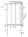
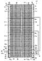
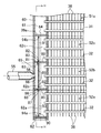
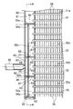
図2及び図3に示すように、室外熱交換器(23)は、一つの第1ヘッダ集合管(60)と、一つの第2ヘッダ集合管(70)と、多数の扁平管(31,32)と、多数のフィン(36)とを備えている。第1ヘッダ集合管(60)、第2ヘッダ集合管(70)、扁平管(31,32)およびフィン(35)は、何れもアルミニウム合金製の部材であって、互いにロウ付けによって接合されている。
<Configuration of outdoor heat exchanger>
As shown in FIGS. 2 and 3, the outdoor heat exchanger (23) includes one first header collecting pipe (60), one second header collecting pipe (70), and many flat tubes (31, 31). 32) and a large number of fins (36). The first header collecting pipe (60), the second header collecting pipe (70), the flat pipe (31, 32) and the fin (35) are all made of an aluminum alloy and are joined to each other by brazing. Yes.
なお、詳しくは後述するが、室外熱交換器(23)は、主熱交換領域(51)と補助熱交換領域(52)に区分されている。この室外熱交換器(23)では、一部の扁平管(32)が補助熱交換領域(52)を構成し、残りの扁平管(31)が主熱交換領域(51)を構成している。 Although described later in detail, the outdoor heat exchanger (23) is divided into a main heat exchange region (51) and an auxiliary heat exchange region (52). In this outdoor heat exchanger (23), some flat tubes (32) constitute an auxiliary heat exchange region (52), and the remaining flat tubes (31) constitute a main heat exchange region (51). .
第1ヘッダ集合管(60)と第2ヘッダ集合管(70)は、何れも両端が閉塞された細長い円筒状に形成されている。図2及び図3において、第1ヘッダ集合管(60)は室外熱交換器(23)の左端に、第2ヘッダ集合管(70)は室外熱交換器(23)の右端に、それぞれ起立した状態で設置されている。つまり、第1ヘッダ集合管(60)及び第2ヘッダ集合管(70)は、それぞれの軸方向が上下方向となる状態で設置されている。 Each of the first header collecting pipe (60) and the second header collecting pipe (70) is formed in an elongated cylindrical shape whose both ends are closed. 2 and 3, the first header collecting pipe (60) stood up at the left end of the outdoor heat exchanger (23), and the second header collecting pipe (70) stood up at the right end of the outdoor heat exchanger (23). It is installed in a state. That is, the first header collecting pipe (60) and the second header collecting pipe (70) are installed in a state where the respective axial directions are in the vertical direction.
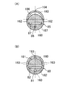
図4に示すように、扁平管(31,32)は、その断面形状が扁平な長円形となった伝熱管である。図3に示すように、室外熱交換器(23)において、複数の扁平管(31,32)は、その伸長方向が左右方向となり、それぞれの平坦な側面が対向する状態で配置されている。また、複数の扁平管(31,32)は、互いに一定の間隔をおいて上下に並んで配置され、互いに実質的に平行となっている。各扁平管(31,32)は、その一端が第1ヘッダ集合管(60)に挿入され、その他端が第2ヘッダ集合管(70)に挿入されている。 As shown in FIG. 4, the flat tubes (31, 32) are heat transfer tubes whose cross-sectional shape is a flat oval. As shown in FIG. 3, in the outdoor heat exchanger (23), the plurality of flat tubes (31, 32) are arranged in a state in which the extending direction is the left-right direction and the flat side surfaces face each other. In addition, the plurality of flat tubes (31, 32) are arranged side by side at regular intervals and are substantially parallel to each other. Each flat tube (31, 32) has one end inserted into the first header collecting tube (60) and the other end inserted into the second header collecting tube (70).
図4に示すように、各扁平管(31,32)には、複数の流体通路(34)が形成されている。各流体通路(34)は、扁平管(31,32)の伸長方向に延びる通路である。各扁平管(31,32)において、複数の流体通路(34)は、扁平管(31,32)の幅方向(即ち、長手方向と直交する方向)に一列に並んでいる。各扁平管(31,32)に形成された複数の流体通路(34)は、それぞれの一端が第1ヘッダ集合管(60)の内部空間に連通し、それぞれの他端が第2ヘッダ集合管(70)の内部空間に連通している。室外熱交換器(23)へ供給された冷媒は、扁平管(31,32)の流体通路(34)を流れる間に空気と熱交換する。 As shown in FIG. 4, a plurality of fluid passages (34) are formed in each flat tube (31, 32). Each fluid passage (34) is a passage extending in the extending direction of the flat tube (31, 32). In each flat tube (31, 32), the plurality of fluid passages (34) are arranged in a line in the width direction of the flat tube (31, 32) (that is, the direction orthogonal to the longitudinal direction). One end of each of the plurality of fluid passages (34) formed in each flat tube (31, 32) communicates with the internal space of the first header collecting pipe (60), and the other end of each fluid passage (34) is the second header collecting pipe. It communicates with the internal space of (70). The refrigerant supplied to the outdoor heat exchanger (23) exchanges heat with air while flowing through the fluid passage (34) of the flat tubes (31, 32).
図4に示すように、フィン(36)は、金属板をプレス加工することによって形成された縦長の板状フィンである。フィン(36)には、フィン(36)の前縁(即ち、風上側の縁部)からフィン(36)の幅方向に延びる細長い切り欠き部(45)が、多数形成されている。フィン(36)では、多数の切り欠き部(45)が、フィン(36)の長手方向(上下方向)に一定の間隔で形成されている。切り欠き部(45)の風下寄りの部分は、管挿入部(46)を構成している。管挿入部(46)は、上下方向の幅が扁平管(31,32)の厚さと実質的に等しく、長さが扁平管(31,32)の幅と実質的に等しい。扁平管(31,32)は、フィン(36)の管挿入部(46)に挿入され、管挿入部(46)の周縁部とロウ付けによって接合される。また、フィン(36)には、伝熱を促進するためのルーバー(40)が形成されている。そして、複数のフィン(36)は、扁平管(31,32)の伸長方向に配列されることで、隣り合う扁平管(31,32)の間を空気が流れる複数の通風路(38)に区画している。 As shown in FIG. 4, the fin (36) is a vertically long plate-like fin formed by pressing a metal plate. The fin (36) is formed with a number of elongated notches (45) extending in the width direction of the fin (36) from the front edge of the fin (36) (that is, the windward edge). In the fin (36), a large number of notches (45) are formed at regular intervals in the longitudinal direction (vertical direction) of the fin (36). The portion closer to the lee of the notch (45) constitutes the tube insertion portion (46). The tube insertion portion (46) has a vertical width substantially equal to the thickness of the flat tube (31, 32) and a length substantially equal to the width of the flat tube (31, 32). The flat tubes (31, 32) are inserted into the tube insertion portion (46) of the fin (36) and joined to the peripheral portion of the tube insertion portion (46) by brazing. Moreover, the louver (40) for promoting heat transfer is formed in the fin (36). The plurality of fins (36) are arranged in the extending direction of the flat tubes (31, 32) so that the air flows between the adjacent flat tubes (31, 32) into the plurality of ventilation paths (38). It is partitioned.
図2及び図3に示すように、室外熱交換器(23)は、上下に二つの熱交換領域(51,52)に区分されている。室外熱交換器(23)では、上側の熱交換領域が主熱交換領域(51)となり、下側の熱交換領域が補助熱交換領域(52)となっている。 As shown in FIGS. 2 and 3, the outdoor heat exchanger (23) is divided into two heat exchange regions (51, 52) on the top and bottom. In the outdoor heat exchanger (23), the upper heat exchange region is the main heat exchange region (51), and the lower heat exchange region is the auxiliary heat exchange region (52).
各熱交換領域(51,52)は、上下に三つずつの熱交換部(51a〜51c,52a〜52c)に区分されている。つまり、室外熱交換器(23)では、主熱交換領域(51)と補助熱交換領域(52)のそれぞれが、複数且つ互いに同数の熱交換部(51a〜51c,52a〜52c)に区分されている。なお、各熱交換領域(51,52)に形成される熱交換部(51a〜51c,52a〜52c)の数は、二つであってもよいし、四つ以上であってもよい。 Each heat exchange area (51, 52) is divided into three heat exchange sections (51a to 51c, 52a to 52c). That is, in the outdoor heat exchanger (23), each of the main heat exchange region (51) and the auxiliary heat exchange region (52) is divided into a plurality of heat exchange portions (51a to 51c, 52a to 52c). ing. In addition, the number of the heat exchange parts (51a-51c, 52a-52c) formed in each heat exchange area | region (51,52) may be two, and may be four or more.
具体的に、主熱交換領域(51)には、下から上に向かって順に、第1主熱交換部(51a)と、第2主熱交換部(51b)と、第3主熱交換部(51c)とが形成されている。補助熱交換領域(52)には、下から上に向かって順に、第1補助熱交換部(52a)と、第2補助熱交換部(52b)と、第3補助熱交換部(52c)とが形成されている。各主熱交換部(51a〜51c)と各補助熱交換部(52a〜52c)は、扁平管(31,32)が複数本ずつ備えている。また、図3に示すように、各主熱交換部(51a〜51c)を構成する扁平管(31)の本数は、各補助熱交換部(52a〜52c)を構成する扁平管(32)の本数よりも多い。従って、主熱交換領域(51)を構成する扁平管(31)の本数は、補助熱交換領域(52)を構成する扁平管(32)の本数よりも多い。なお、本実施形態の室外熱交換器(23)において、各補助熱交換部(52a〜52c)を構成する扁平管(32)の本数は、三本である。 Specifically, in the main heat exchange region (51), the first main heat exchange unit (51a), the second main heat exchange unit (51b), and the third main heat exchange unit are sequentially arranged from the bottom to the top. (51c) is formed. In the auxiliary heat exchange region (52), in order from bottom to top, a first auxiliary heat exchange unit (52a), a second auxiliary heat exchange unit (52b), and a third auxiliary heat exchange unit (52c) Is formed. Each of the main heat exchange units (51a to 51c) and each of the auxiliary heat exchange units (52a to 52c) includes a plurality of flat tubes (31, 32). Moreover, as shown in FIG. 3, the number of the flat tubes (31) constituting each main heat exchange section (51a to 51c) is equal to the number of the flat tubes (32) constituting each auxiliary heat exchange section (52a to 52c). More than the number. Therefore, the number of flat tubes (31) constituting the main heat exchange region (51) is larger than the number of flat tubes (32) constituting the auxiliary heat exchange region (52). In addition, in the outdoor heat exchanger (23) of this embodiment, the number of the flat tubes (32) which comprise each auxiliary heat exchange part (52a-52c) is three.
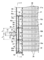
図3に示すように、第1ヘッダ集合管(60)の内部空間は、仕切板(39a)によって上下に仕切られている。第1ヘッダ集合管(60)では、仕切板(39a)の上側の空間が上側空間(61)となり、仕切板(39a)の下側の空間が下側空間(62)となっている。 As shown in FIG. 3, the internal space of the first header collecting pipe (60) is partitioned vertically by a partition plate (39a). In the first header collecting pipe (60), the space above the partition plate (39a) is the upper space (61), and the space below the partition plate (39a) is the lower space (62).
上側空間(61)は、主熱交換領域(51)に対応した主連通空間を構成している。上側空間(61)は、主熱交換領域(51)を構成する扁平管(31)の全てと連通する単一の空間である。つまり、上側空間(61)は、各主熱交換部(51a〜51c)の扁平管(31)と連通している。 The upper space (61) constitutes a main communication space corresponding to the main heat exchange region (51). The upper space (61) is a single space communicating with all of the flat tubes (31) constituting the main heat exchange region (51). That is, the upper space (61) communicates with the flat tube (31) of each main heat exchange section (51a to 51c).
下側空間(62)は、補助熱交換領域(52)に対応した補助連通空間を構成している。詳細は後述するが、下側空間(62)は、補助熱交換部(52a〜52c)と同数(本実施形態では三つ)の連通室(62a〜62c)に区画されている。最も下方に位置する第1連通室(62a)は、第1補助熱交換部(52a)を構成する全ての扁平管(32)と連通する。第1連通室(62a)の上方に位置する第2連通室(62b)は、第2補助熱交換部(52b)を構成する全ての扁平管(32)と連通する。最も上方に位置する第3連通室(62c)は、第3補助熱交換部(52c)を構成する全ての扁平管(32)と連通する。 The lower space (62) constitutes an auxiliary communication space corresponding to the auxiliary heat exchange region (52). Although details will be described later, the lower space (62) is partitioned into the same number (three in the present embodiment) of communication chambers (62a to 62c) as the auxiliary heat exchange units (52a to 52c). The lowermost first communication chamber (62a) communicates with all the flat tubes (32) constituting the first auxiliary heat exchange section (52a). The second communication chamber (62b) located above the first communication chamber (62a) communicates with all the flat tubes (32) constituting the second auxiliary heat exchange section (52b). The uppermost third communication chamber (62c) communicates with all the flat tubes (32) constituting the third auxiliary heat exchange section (52c).
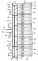
第2ヘッダ集合管(70)の内部空間は、主熱交換領域(51)に対応した主連通空間(71)と、補助熱交換領域(52)に対応した補助連通空間(72)とに区分されている。 The internal space of the second header collecting pipe (70) is divided into a main communication space (71) corresponding to the main heat exchange area (51) and an auxiliary communication space (72) corresponding to the auxiliary heat exchange area (52). Has been.
主連通空間(71)は、二枚の仕切板(39c)によって上下に仕切られている。この仕切板(39c)は、主連通空間(71)を、主熱交換部(51a〜51c)と同数(本実施形態では三つ)の部分空間(71a〜71c)に区画している。最も下方に位置する第1部分空間(71a)は、第1主熱交換部(51a)を構成する全ての扁平管(31)と連通する。第1部分空間(71a)の上方に位置する第2部分空間(71b)は、第2主熱交換部(51b)を構成する全ての扁平管(31)と連通する。最も上方に位置する第3部分空間(71c)は、第3主熱交換部(51c)を構成する全ての扁平管(31)と連通する。 The main communication space (71) is partitioned up and down by two partition plates (39c). The partition plate (39c) divides the main communication space (71) into the same number (three in this embodiment) of partial spaces (71a to 71c) as the main heat exchange portions (51a to 51c). The lowermost first partial space (71a) communicates with all the flat tubes (31) constituting the first main heat exchange section (51a). The second partial space (71b) located above the first partial space (71a) communicates with all the flat tubes (31) constituting the second main heat exchange section (51b). The uppermost third partial space (71c) communicates with all the flat tubes (31) constituting the third main heat exchange section (51c).
補助連通空間(72)は、二枚の仕切板(39d)によって上下に仕切られている。この仕切板(39d)は、補助連通空間(72)を、補助熱交換部(52a〜52c)と同数(本実施形態では三つ)の部分空間(72a〜72c)に区画している。最も下方に位置する第4部分空間(72a)は、第1補助熱交換部(52a)を構成する全ての扁平管(32)と連通する。第4部分空間(72a)の上方に位置する第5部分空間(72b)は、第2補助熱交換部(52b)を構成する全ての扁平管(32)と連通する。最も上方に位置する第6部分空間(72c)は、第3補助熱交換部(52c)を構成する全ての扁平管(32)と連通する。 The auxiliary communication space (72) is partitioned vertically by two partition plates (39d). The partition plate (39d) divides the auxiliary communication space (72) into the same number (three in the present embodiment) of partial spaces (72a to 72c) as the auxiliary heat exchange units (52a to 52c). The lowermost fourth partial space (72a) communicates with all the flat tubes (32) constituting the first auxiliary heat exchange section (52a). The fifth partial space (72b) located above the fourth partial space (72a) communicates with all the flat tubes (32) constituting the second auxiliary heat exchange section (52b). The sixth partial space (72c) located at the uppermost position communicates with all the flat tubes (32) constituting the third auxiliary heat exchange section (52c).
第2ヘッダ集合管(70)には、二本の接続用配管(76,77)が取り付けられている。これら接続用配管(76,77)は、何れも円管である。 Two connection pipes (76, 77) are attached to the second header collecting pipe (70). These connection pipes (76, 77) are all circular pipes.
第1接続用配管(76)は、その一端が第2主熱交換部(51b)に対応する第2部分空間(71b)に接続され、その他端が第1補助熱交換部(52a)に対応する第4部分空間(72a)に接続される。第2接続用配管(77)は、その一端が第3主熱交換部(51c)に対応する第3部分空間(71c)に接続され、その他端が第2補助熱交換部(52b)に対応する第5部分空間(72b)に接続される。また、第2ヘッダ集合管(70)では、第3補助熱交換部(52c)に対応する第6部分空間(72c)と、第1主熱交換部(51a)に対応する第1部分空間(71a)とが、互いに連続した一つの空間を形成している。 The first connection pipe (76) has one end connected to the second partial space (71b) corresponding to the second main heat exchange part (51b) and the other end corresponding to the first auxiliary heat exchange part (52a). Connected to the fourth partial space (72a). The second connection pipe (77) has one end connected to the third partial space (71c) corresponding to the third main heat exchange part (51c) and the other end corresponding to the second auxiliary heat exchange part (52b). Connected to the fifth partial space (72b). Further, in the second header collecting pipe (70), a sixth partial space (72c) corresponding to the third auxiliary heat exchange section (52c) and a first partial space corresponding to the first main heat exchange section (51a) ( 71a) form one continuous space.
このように、本実施形態の室外熱交換器(23)では、第1主熱交換部(51a)と第3補助熱交換部(52c)が直列に接続され、第2主熱交換部(51b)と第1補助熱交換部(52a)が直列に接続され、第3主熱交換部(51c)と第2補助熱交換部(52b)が直列に接続されている。 Thus, in the outdoor heat exchanger (23) of this embodiment, the 1st main heat exchange part (51a) and the 3rd auxiliary heat exchange part (52c) are connected in series, and the 2nd main heat exchange part (51b ) And the first auxiliary heat exchanger (52a) are connected in series, and the third main heat exchanger (51c) and the second auxiliary heat exchanger (52b) are connected in series.
図2及び図3に示すように、室外熱交換器(23)には、液側接続管(55)とガス側接続管(57)とが設けられている。液側接続管(55)及びガス側接続管(57)は、円管状に形成されたアルミニウム合金製の部材である。液側接続管(55)及びガス側接続管(57)は、第1ヘッダ集合管(60)とロウ付けによって接合されている。 As shown in FIGS. 2 and 3, the outdoor heat exchanger (23) is provided with a liquid side connection pipe (55) and a gas side connection pipe (57). The liquid side connecting pipe (55) and the gas side connecting pipe (57) are aluminum alloy members formed in a circular tube shape. The liquid side connection pipe (55) and the gas side connection pipe (57) are joined to the first header collecting pipe (60) by brazing.
詳細は後述するが、管状部材である液側接続管(55)の一端は、第1ヘッダ集合管(60)の下部に接続され、下側空間(62)に連通している。液側接続管(55)の他端は、室外熱交換器(23)と膨張弁(24)を繋ぐ銅製の配管(17)に、継手(図示せず)を介して接続されている。 Although details will be described later, one end of the liquid side connection pipe (55), which is a tubular member, is connected to the lower part of the first header collecting pipe (60) and communicates with the lower space (62). The other end of the liquid side connection pipe (55) is connected to a copper pipe (17) connecting the outdoor heat exchanger (23) and the expansion valve (24) via a joint (not shown).
ガス側接続管(57)の一端は、第1ヘッダ集合管(60)の上部に接続され、上側空間(61)に連通している。ガス側接続管(57)の他端は、室外熱交換器(23)と四方切換弁(22)の第3のポートを繋ぐ銅製の配管(18)に、継手(図示せず)を介して接続されている。 One end of the gas side connection pipe (57) is connected to the upper part of the first header collecting pipe (60) and communicates with the upper space (61). The other end of the gas side connection pipe (57) is connected to a copper pipe (18) connecting the outdoor heat exchanger (23) and the third port of the four-way switching valve (22) via a joint (not shown). It is connected.
〈第1ヘッダ集合管の下部の構成〉
第1ヘッダ集合管(60)の下部の構造について、図5〜図7を適宜参照しながら詳細に説明する。なお、この説明では、第1ヘッダ集合管(60)の側面のうち扁平管(32)側の部分を「前面」とし、第1ヘッダ集合管(60)の側面のうち扁平管(32)とは反対側の部分を「背面」とする。
<Configuration of the lower part of the first header collecting pipe>
The structure of the lower part of the first header collecting pipe (60) will be described in detail with reference to FIGS. In this description, the portion on the flat tube (32) side of the side surface of the first header collecting pipe (60) is referred to as “front surface”, and the flat tube (32) of the side surface of the first header collecting pipe (60) is The opposite side is the “back”.
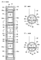
第1ヘッダ集合管(60)の下側空間(62)には、上側横仕切板(80)と、下側横仕切板(85)と、縦仕切板(90)とが一つずつ設置されている(図5を参照)。この下側空間(62)は、これらの横仕切板(80,85)及び縦仕切板(90)によって、三つの連通室(62a〜62c)と一つの混合室(63)とに仕切られている。上側横仕切板(80)、下側横仕切板(85)、及び縦仕切板(90)の材質は、アルミニウム合金である。 In the lower space (62) of the first header collecting pipe (60), an upper horizontal partition plate (80), a lower horizontal partition plate (85), and a vertical partition plate (90) are installed one by one. (See FIG. 5). The lower space (62) is divided into three communication chambers (62a to 62c) and one mixing chamber (63) by the horizontal partition plates (80, 85) and the vertical partition plate (90). Yes. The material of the upper horizontal partition plate (80), the lower horizontal partition plate (85), and the vertical partition plate (90) is an aluminum alloy.
上側横仕切板(80)及び下側横仕切板(85)のそれぞれは、円板状に形成されて下側空間(62)を上下に仕切っている。上側横仕切板(80)及び下側横仕切板(85)は、ロウ付けによって第1ヘッダ集合管(60)と接合されている。上側横仕切板(80)は、第2補助熱交換部(52b)と第3補助熱交換部(52c)の境界に配置され、第2連通室(62b)と第3連通室(62c)を仕切っている。下側横仕切板(85)は、第1補助熱交換部(52a)と第2補助熱交換部(52b)の境界に配置され、第1連通室(62a)と第2連通室(62b)を仕切っている。 Each of the upper lateral partition plate (80) and the lower lateral partition plate (85) is formed in a disc shape and partitions the lower space (62) vertically. The upper horizontal partition plate (80) and the lower horizontal partition plate (85) are joined to the first header collecting pipe (60) by brazing. The upper horizontal partition plate (80) is disposed at the boundary between the second auxiliary heat exchange part (52b) and the third auxiliary heat exchange part (52c), and connects the second communication chamber (62b) and the third communication chamber (62c). Partitioning. The lower horizontal partition plate (85) is disposed at the boundary between the first auxiliary heat exchange section (52a) and the second auxiliary heat exchange section (52b), and is connected to the first communication chamber (62a) and the second communication chamber (62b). Partitioning.
上側横仕切板(80)及び下側横仕切板(85)のそれぞれには、スリット孔(82,87)と連通用貫通孔(81,86)とが一つずつ形成されている(図5及び図6を参照)。 Each of the upper lateral partition plate (80) and the lower lateral partition plate (85) is formed with one slit hole (82, 87) and one through hole for communication (81, 86) (FIG. 5). And FIG. 6).
スリット孔(82,87)は、細長い長方形状の孔であって、横仕切板(80,85)を厚さ方向に貫通している。スリット孔(82,87)の長辺は、扁平管(32)の端面と実質的に平行である。各横仕切板(80,85)において、スリット孔(82,87)は、第1ヘッダ集合管(60)の背面寄りに位置している。スリット孔(82,87)は、その幅が縦仕切板(90)の厚さとほぼ同じであり、その長さが縦仕切板(90)の幅とほぼ同じである。 The slit holes (82, 87) are elongated rectangular holes, and penetrate the horizontal partition plates (80, 85) in the thickness direction. The long sides of the slit holes (82, 87) are substantially parallel to the end face of the flat tube (32). In each horizontal partition plate (80, 85), the slit hole (82, 87) is located closer to the back surface of the first header collecting pipe (60). The width of the slit holes (82, 87) is substantially the same as the thickness of the vertical partition plate (90), and the length thereof is substantially the same as the width of the vertical partition plate (90).
連通用貫通孔(81,86)は、円形の孔であって、横仕切板(80,85)を厚さ方向に貫通している。各横仕切板(80,85)において、連通用貫通孔(81,86)は、スリット孔(82,87)よりも更に第1ヘッダ集合管(60)の背面寄りに位置している。また、上側横仕切板(80)及び下側横仕切板(85)の連通用貫通孔(81,86)は、それぞれの直径が互いに等しい。 The communication through holes (81, 86) are circular holes and penetrate the horizontal partition plates (80, 85) in the thickness direction. In each horizontal partition plate (80, 85), the communication through holes (81, 86) are located closer to the back surface of the first header collecting pipe (60) than the slit holes (82, 87). In addition, the diameters of the through holes (81, 86) for communication of the upper horizontal partition plate (80) and the lower horizontal partition plate (85) are equal to each other.
縦仕切板(90)は、縦長の長方形板状に形成されている(図7を参照)。 The vertical partition plate (90) is formed in a vertically long rectangular plate shape (see FIG. 7).
縦仕切板(90)は、上側横仕切板(80)のスリット孔(82)と、下側横仕切板(85)のスリット孔(87)とに挿通されている(図5及び図6を参照)。この縦仕切板(90)は、第1ヘッダ集合管(60)へ差し込まれた扁平管(32)の端面と向かい合っている。 The vertical partition plate (90) is inserted through the slit hole (82) of the upper horizontal partition plate (80) and the slit hole (87) of the lower horizontal partition plate (85) (see FIGS. 5 and 6). reference). The vertical partition plate (90) faces the end surface of the flat tube (32) inserted into the first header collecting tube (60).
縦仕切板(90)は、その下端が第1ヘッダ集合管(60)の底部に当接し、その上端が仕切板(39a)に当接している。また、縦仕切板(90)は、幅方向(図6における左右方向)の両側部が第1ヘッダ集合管(60)の内周面に接している。縦仕切板(90)は、他の部材に対して接合されていない。この縦仕切板(90)は、各横仕切板(80,85)のスリット孔(82,87)に差し込まれ、仕切板(39a)と第1ヘッダ集合管(60)の底部に当接することによって、その姿勢が保持されている。 The vertical partition plate (90) has a lower end in contact with the bottom of the first header collecting pipe (60) and an upper end in contact with the partition plate (39a). The vertical partition plate (90) is in contact with the inner peripheral surface of the first header collecting pipe (60) at both sides in the width direction (left and right direction in FIG. 6). The vertical partition plate (90) is not joined to other members. The vertical partition plate (90) is inserted into the slit hole (82, 87) of each horizontal partition plate (80, 85) and abuts on the partition plate (39a) and the bottom of the first header collecting pipe (60). This holds the posture.
縦仕切板(90)は、上側横仕切板(80)よりも上側の部分が上側部分(91)となり、上側横仕切板(80)と下側横仕切板(85)の間の部分が中間部分(92)となり、下側横仕切板(85)よりも下側の部分が下側部分(93)となっている(図5及び図6を参照)。 In the vertical partition plate (90), the upper portion of the upper horizontal partition plate (80) is the upper portion (91), and the portion between the upper horizontal partition plate (80) and the lower horizontal partition plate (85) is intermediate. A portion (92) is formed, and a portion below the lower horizontal partition plate (85) is a lower portion (93) (see FIGS. 5 and 6).
縦仕切板(90)の中間部分(92)は、上側横仕切板(80)と下側横仕切板(85)の間の空間を、第1ヘッダ集合管(60)の前面側に位置する第2連通室(62b)と、その背面側に位置する混合室(63)とに仕切っている。つまり、第1ヘッダ集合管(60)内では、第2連通室(62b)の背面側に混合室(63)が形成されている。この混合室(63)は、縦仕切板(90)の中間部分(92)と、上側横仕切板(80)と、下側横仕切板(85)と、第1ヘッダ集合管(60)の側壁部とによって囲まれている。 The middle part (92) of the vertical partition (90) is located in the space between the upper horizontal partition (80) and the lower horizontal partition (85) on the front side of the first header collecting pipe (60). It is partitioned into a second communication chamber (62b) and a mixing chamber (63) located on the back side thereof. That is, in the first header collecting pipe (60), the mixing chamber (63) is formed on the back side of the second communication chamber (62b). The mixing chamber (63) includes an intermediate portion (92) of the vertical partition plate (90), an upper horizontal partition plate (80), a lower horizontal partition plate (85), and a first header collecting pipe (60). It is surrounded by the side wall.
縦仕切板(90)には、長方形状の開口部(94a,94b)と、円形の連通用貫通孔(95,95)とが二つずつ形成されている。各開口部(94a,94b)と各連通用貫通孔(95,95)は、縦仕切板(90)を厚さ方向に貫通している。 Two rectangular openings (94a, 94b) and two circular communication through holes (95, 95) are formed in the vertical partition plate (90). Each opening (94a, 94b) and each communicating through hole (95, 95) penetrate the vertical partition plate (90) in the thickness direction.
開口部(94a,94b)は、縦仕切板(90)の上側部分(91)と下側部分(93)とに一つずつ形成されている。上側の開口部(94b)は、縦仕切板(90)の上側部分(91)の大半を占めている。従って、上側横仕切板(80)の上側に位置する第3連通室(62c)は、縦仕切板(90)の両側の部分が実質的に一つの空間となっている。下側の開口部(94a)は、縦仕切板(90)の下側部分(93)の大半を占めている。従って、下側横仕切板(85)の下側に位置する第1連通室(62a)は、縦仕切板(90)の両側の部分が実質的に一つの空間となっている。 One opening (94a, 94b) is formed in each of the upper part (91) and the lower part (93) of the vertical partition plate (90). The upper opening (94b) occupies most of the upper part (91) of the vertical partition (90). Accordingly, in the third communication chamber (62c) located on the upper side of the upper horizontal partition plate (80), the portions on both sides of the vertical partition plate (90) are substantially one space. The lower opening (94a) occupies most of the lower part (93) of the vertical partition (90). Therefore, in the first communication chamber (62a) located on the lower side of the lower horizontal partition plate (85), both side portions of the vertical partition plate (90) are substantially one space.
連通用貫通孔(95)は、縦仕切板(90)の中間部分(92)に形成されている。連通用貫通孔(95)は、直径が2mm程度の円形の孔であって、中間部分(92)の上下方向の中央よりも上側と下側に一つずつ配置されている。 The communication through hole (95) is formed in an intermediate portion (92) of the vertical partition plate (90). The communication through hole (95) is a circular hole having a diameter of about 2 mm, and is arranged one above and below the center in the vertical direction of the intermediate portion (92).
このように、縦仕切板(90)は、その長手方向の各端部に開口部(94a,94b)が一つずつ形成され、開口部(94a,94b)の間に二つの連通用貫通孔(95,95)が形成されている。二つの開口部(94a,94b)と二つの連通用貫通孔(95,95)とは、縦仕切板(90)の長手方向に一列に配置されている。そして、縦仕切板(90)の形状は、上下対称で且つ左右対称となっている。 Thus, the vertical partition plate (90) has one opening (94a, 94b) at each end in the longitudinal direction, and two communication through holes between the openings (94a, 94b). (95, 95) is formed. The two openings (94a, 94b) and the two communication through holes (95, 95) are arranged in a line in the longitudinal direction of the vertical partition plate (90). The shape of the vertical partition (90) is vertically symmetric and symmetric.
上述したように、縦仕切板(90)には連通用貫通孔(95)が、上側横仕切板(80)には連通用貫通孔(81)が、下側横仕切板(85)には連通用貫通孔(86)が、それぞれ形成されている。縦仕切板(90)の連通用貫通孔(95)は、混合室(63)を第2連通室(62b)と連通させる。上側横仕切板(80)の連通用貫通孔(95)は、混合室(63)を第3連通室(62c)と連通させる。下側横仕切板(85)の連通用貫通孔(86)は、混合室(63)を第1連通室(62a)と連通させる。これらの連通用貫通孔(81,86,95)は、混合室(63)の冷媒を各連通室(62a〜62c)へ分配する分配通路(65)を構成している。 As described above, the vertical partition plate (90) has a communication through hole (95), the upper horizontal partition plate (80) has a communication through hole (81), and the lower horizontal partition plate (85) has a communication through hole. A communication through hole (86) is formed. The communication through hole (95) of the vertical partition (90) allows the mixing chamber (63) to communicate with the second communication chamber (62b). The communication through hole (95) of the upper horizontal partition (80) allows the mixing chamber (63) to communicate with the third communication chamber (62c). The communication through hole (86) of the lower horizontal partition (85) allows the mixing chamber (63) to communicate with the first communication chamber (62a). These through holes (81, 86, 95) for communication constitute distribution passages (65) for distributing the refrigerant in the mixing chamber (63) to the respective communication chambers (62a to 62c).
第1ヘッダ集合管(60)の側壁部には、液側接続管(55)を差し込むための接続口(66)が形成されている。接続口(66)は、円形の貫通孔である。接続口(66)は、第1ヘッダ集合管(60)のうち上側横仕切板(80)と下側横仕切板(85)の間の部分に形成され、混合室(63)に連通している。接続口(66)の中心は、混合室(63)の高さ方向の中央に位置している。従って、図5に示すように、接続口(66)の中心から上側横仕切板(80)の下面までの距離L1と、接続口(66)の中心から下側横仕切板(85)の上面までの距離L2とは、互いに等しい(L1=L2)。また、接続口(66)は、縦仕切板(90)のうち二つの連通用貫通孔(95)の間の部分と向かい合っている。 A connection port (66) for inserting the liquid side connection pipe (55) is formed in the side wall portion of the first header collecting pipe (60). The connection port (66) is a circular through hole. The connection port (66) is formed in a portion of the first header collecting pipe (60) between the upper horizontal partition plate (80) and the lower horizontal partition plate (85), and communicates with the mixing chamber (63). Yes. The center of the connection port (66) is located at the center in the height direction of the mixing chamber (63). Accordingly, as shown in FIG. 5, from the center of the connection port (66) and the distance L 1 to the lower surface of the upper horizontal partition (80), the lower horizontal partition from the center of the connecting port (66) (85) The distance L 2 to the upper surface is equal to each other (L 1 = L 2 ). Further, the connection port (66) faces a portion between the two communication through holes (95) in the vertical partition plate (90).
液側接続管(55)は、第1ヘッダ集合管(60)の接続口(66)へ差し込まれる接続端部(56)が窄まった形状となっている。つまり、液側接続管(55)は、接続端部(56)の内径dが他の部分の内径よりも小さくなっている。また、この接続端部(56)の外径は、接続口(66)の直径と実質的に等しい。本実施形態では、上側横仕切板(80)及び下側横仕切板(85)の連通用貫通孔(81,86)の直径が液側接続管(55)の接続端部(56)の内径よりも小さく、縦仕切板(90)の連通用貫通孔(95)の直径が上側横仕切板(80)及び下側横仕切板(85)の連通用貫通孔(81,86)の直径よりも小さい。また、上側横仕切板(80)の連通用貫通孔(81)の面積および下側横仕切板(85)の連通用貫通孔(86)の面積のそれぞれは、縦仕切板(90)の二つの連通用貫通孔(95)の面積の合計と等しい。 The liquid side connection pipe (55) has a shape in which the connection end (56) inserted into the connection port (66) of the first header collecting pipe (60) is narrowed. That is, in the liquid side connection pipe (55), the inner diameter d of the connection end (56) is smaller than the inner diameter of the other part. Further, the outer diameter of the connection end (56) is substantially equal to the diameter of the connection port (66). In the present embodiment, the diameters of the communication through holes (81, 86) of the upper side partition plate (80) and the lower side partition plate (85) are the inner diameters of the connection end portions (56) of the liquid side connection pipe (55). Smaller than the diameter of the through holes (95) in the vertical partition plate (90) than the through holes (81, 86) in the upper horizontal partition plate (80) and the lower horizontal partition plate (85). Is also small. The area of the communication through hole (81) of the upper horizontal partition plate (80) and the area of the communication through hole (86) of the lower horizontal partition plate (85) are the same as those of the vertical partition plate (90). It is equal to the total area of the two through holes (95) for communication.
〈室外熱交換器における冷媒の流れ/凝縮器の場合〉
空気調和機(10)の冷房運転中には、室外熱交換器(23)が凝縮器として機能する。冷房運転中における室外熱交換器(23)での冷媒の流れを説明する。
<Refrigerant flow in outdoor heat exchanger / condenser>
During the cooling operation of the air conditioner (10), the outdoor heat exchanger (23) functions as a condenser. The flow of the refrigerant in the outdoor heat exchanger (23) during the cooling operation will be described.
室外熱交換器(23)には、圧縮機(21)から吐出されたガス冷媒が供給される。圧縮機(21)から送られたガス冷媒は、ガス側接続管(57)を介して第1ヘッダ集合管(60)の上側空間(61)へ流入した後、主熱交換領域(51)の各扁平管(31)へ分配される。主熱交換領域(51)の各主熱交換部(51a〜51c)において、扁平管(31)の流体通路(34)へ流入した冷媒は、流体通路(34)を流れる間に室外空気へ放熱して凝縮し、その後に第2ヘッダ集合管(70)の対応する各部分空間(71a〜71c)へ流入する。 Gas refrigerant discharged from the compressor (21) is supplied to the outdoor heat exchanger (23). The gas refrigerant sent from the compressor (21) flows into the upper space (61) of the first header collecting pipe (60) via the gas side connection pipe (57), and then flows into the main heat exchange region (51). It is distributed to each flat tube (31). In each main heat exchange section (51a to 51c) of the main heat exchange region (51), the refrigerant flowing into the fluid passage (34) of the flat tube (31) dissipates heat to the outdoor air while flowing through the fluid passage (34). Then, it condenses and then flows into the corresponding partial spaces (71a to 71c) of the second header collecting pipe (70).
主連通空間(71)の各部分空間(71a〜71c)へ流入した冷媒は、補助連通空間(72)の対応する部分空間(72a〜72c)へ送られる。具体的に、主連通空間(71)の第1部分空間(71a)へ流入した冷媒は、下方へ流れ落ちて補助連通空間(72)の第6部分空間(72c)へ流れ込む。主連通空間(71)の第2部分空間(71b)へ流入した冷媒は、第1接続用配管(76)を通って補助連通空間(72)の第4部分空間(72a)へ流入する。主連通空間(71)の第3部分空間(71c)へ流入した冷媒は、第2接続用配管(77)を通って補助連通空間(72)の第5部分空間(72b)へ流入する。 The refrigerant that has flowed into the partial spaces (71a to 71c) of the main communication space (71) is sent to the corresponding partial spaces (72a to 72c) of the auxiliary communication space (72). Specifically, the refrigerant flowing into the first partial space (71a) of the main communication space (71) flows down and flows into the sixth partial space (72c) of the auxiliary communication space (72). The refrigerant flowing into the second partial space (71b) of the main communication space (71) flows into the fourth partial space (72a) of the auxiliary communication space (72) through the first connection pipe (76). The refrigerant that has flowed into the third partial space (71c) of the main communication space (71) flows into the fifth partial space (72b) of the auxiliary communication space (72) through the second connection pipe (77).
補助連通空間(72)の各部分空間(72a〜72c)へ流入した冷媒は、対応する補助熱交換部(52a〜52c)の各扁平管(32)へ分配される。各扁平管(32)の流体通路(34)を流れる冷媒は、室外空気へ放熱して過冷却液となり、その後に第1ヘッダ集合管(60)の下側空間(62)の対応する連通室(62a〜62c)へ流入する。その後、冷媒は、混合室(63)を経て液側接続管(55)へ流れ込み、室外熱交換器(23)から流出してゆく。 The refrigerant that has flowed into the partial spaces (72a to 72c) of the auxiliary communication space (72) is distributed to the flat tubes (32) of the corresponding auxiliary heat exchange sections (52a to 52c). The refrigerant flowing through the fluid passage (34) of each flat tube (32) dissipates heat to the outdoor air and becomes supercooled liquid, and then the corresponding communication chamber in the lower space (62) of the first header collecting pipe (60). (62a to 62c). Thereafter, the refrigerant flows into the liquid side connecting pipe (55) through the mixing chamber (63) and flows out of the outdoor heat exchanger (23).
〈室外熱交換器における冷媒の流れ/蒸発器の場合〉
空気調和機(10)の暖房運転中には、室外熱交換器(23)が蒸発器として機能する。暖房運転中における室外熱交換器(23)での冷媒の流れを説明する。
<Flow of refrigerant in outdoor heat exchanger / Evaporator>
During the heating operation of the air conditioner (10), the outdoor heat exchanger (23) functions as an evaporator. The flow of the refrigerant in the outdoor heat exchanger (23) during the heating operation will be described.
室外熱交換器(23)には、膨張弁(24)を通過する際に膨張して気液二相状態となった冷媒が供給される。膨張弁(24)から流れてきた気液二相状態の冷媒は、接続口(66)に差し込まれた液側接続管(55)を通って第1ヘッダ集合管(60)内の混合室(63)へ流入する。その際、冷媒が液側接続管(55)の接続端部(56)を通過する際にその流速が上昇し、液側接続管(55)から噴出した高流速の冷媒が縦仕切板(90)に衝突する。このため、混合室(63)内では、冷媒が激しく掻き乱され、その冷媒中のガス冷媒と液冷媒が混合される。つまり、混合室(63)内の冷媒が均質化され、混合室(63)内の冷媒の湿り度が概ね均一となる。 The outdoor heat exchanger (23) is supplied with the refrigerant that has expanded into a gas-liquid two-phase state when passing through the expansion valve (24). The gas-liquid two-phase refrigerant flowing from the expansion valve (24) passes through the liquid side connection pipe (55) inserted into the connection port (66), and is mixed in the mixing chamber (60) in the first header collecting pipe (60). 63). At that time, when the refrigerant passes through the connection end (56) of the liquid side connection pipe (55), the flow rate rises, and the high flow rate refrigerant ejected from the liquid side connection pipe (55) becomes the vertical partition plate (90 ). For this reason, in the mixing chamber (63), the refrigerant is vigorously disturbed, and the gas refrigerant and liquid refrigerant in the refrigerant are mixed. That is, the refrigerant in the mixing chamber (63) is homogenized, and the wetness of the refrigerant in the mixing chamber (63) becomes substantially uniform.
混合室(63)内の冷媒は、各連通室(62a〜62c)へ分配される。つまり、混合室(63)内の冷媒は、下側横仕切板(85)の連通用貫通孔(86)を通って第1連通室(62a)へ流入し、縦仕切板(90)の連通用貫通孔(95)を通って第2連通室(62b)へ流入し、上側横仕切板(80)の連通用貫通孔(81)を通って第3連通室(62c)へ流入する。 The refrigerant in the mixing chamber (63) is distributed to the communication chambers (62a to 62c). That is, the refrigerant in the mixing chamber (63) flows into the first communication chamber (62a) through the communication through hole (86) of the lower horizontal partition plate (85), and communicates with the vertical partition plate (90). It flows into the second communication chamber (62b) through the communication through hole (95), and flows into the third communication chamber (62c) through the communication through hole (81) of the upper lateral partition plate (80).
上述したように、混合室(63)内の気液二相状態の冷媒は、均質化されている。このため、各連通室(62a〜62c)へ混合室(63)から流入する冷媒の湿り度は、概ね同じになる。また、上述したように、上側横仕切板(80)の連通用貫通孔(81)の面積および下側横仕切板(85)の連通用貫通孔(86)の面積のそれぞれは、縦仕切板(90)の二つの連通用貫通孔(95)の面積の合計と等しい。このため、各連通室(62a〜62c)へ混合室(63)から流入する冷媒の質量流量も、概ね同じになる。 As described above, the gas-liquid two-phase refrigerant in the mixing chamber (63) is homogenized. For this reason, the wetness degree of the refrigerant | coolant which flows in from each mixing chamber (62a-62c) from a mixing chamber (63) becomes substantially the same. As described above, the area of the communication through hole (81) of the upper horizontal partition plate (80) and the area of the communication through hole (86) of the lower horizontal partition plate (85) It is equal to the sum of the areas of the two through holes (95) for (90). For this reason, the mass flow rate of the refrigerant flowing from the mixing chamber (63) into the communication chambers (62a to 62c) is also substantially the same.
第1ヘッダ集合管(60)の各連通室(62a〜62c)へ流入した冷媒は、対応する補助熱交換部(52a〜52c)の各扁平管(32)へ分配される。各扁平管(32)の流体通路(34)へ流入した冷媒は、流体通路(34)を流れる間に室外空気から吸熱し、一部の液冷媒が蒸発する。扁平管(32)の流体通路(34)を通過した冷媒は、第2ヘッダ集合管(70)の補助連通空間(72)の対応する部分空間(72a〜72c)へ流入する。この部分空間(72a〜72c)へ流入した冷媒は、依然として気液二相状態のままである。 The refrigerant that has flowed into the communication chambers (62a to 62c) of the first header collecting pipe (60) is distributed to the flat tubes (32) of the corresponding auxiliary heat exchange sections (52a to 52c). The refrigerant flowing into the fluid passage (34) of each flat tube (32) absorbs heat from the outdoor air while flowing through the fluid passage (34), and a part of the liquid refrigerant evaporates. The refrigerant that has passed through the fluid passage (34) of the flat tube (32) flows into the corresponding partial spaces (72a to 72c) of the auxiliary communication space (72) of the second header collecting pipe (70). The refrigerant that has flowed into the partial spaces (72a to 72c) still remains in a gas-liquid two-phase state.
補助連通空間(72)の各部分空間(72a〜72c)へ流入した冷媒は、主連通空間(71)の対応する部分空間(71a〜71c)へ送られる。具体的に、補助連通空間(72)の第4部分空間(72a)へ流入した冷媒は、第1接続用配管(76)を通って主連通空間(71)の第2部分空間(71b)へ流入する。補助連通空間(72)の第5部分空間(72b)へ流入した冷媒は、第2接続用配管(77)を通って主連通空間(71)の第3部分空間(71c)へ流入する。補助連通空間(72)の第6部分空間(72c)へ流入した冷媒は、上方へ向かって流れて主連通空間(71)の第1部分空間(71a)へ流入する。 The refrigerant that has flowed into the partial spaces (72a to 72c) of the auxiliary communication space (72) is sent to the corresponding partial spaces (71a to 71c) of the main communication space (71). Specifically, the refrigerant flowing into the fourth partial space (72a) of the auxiliary communication space (72) passes through the first connection pipe (76) to the second partial space (71b) of the main communication space (71). Inflow. The refrigerant that has flowed into the fifth partial space (72b) of the auxiliary communication space (72) flows into the third partial space (71c) of the main communication space (71) through the second connection pipe (77). The refrigerant flowing into the sixth partial space (72c) of the auxiliary communication space (72) flows upward and flows into the first partial space (71a) of the main communication space (71).
主連通空間(71)の各部分空間(71a〜71c)へ流入した冷媒は、対応する主熱交換部(51a〜51c)の各扁平管(31)へ分配される。各扁平管(31)の流体通路(34)を流れる冷媒は、室外空気から吸熱して蒸発し、実質的にガス単相状態となった後に、第1ヘッダ集合管(60)の上側空間(61)へ流入する。その後、冷媒は、ガス側接続管(57)を通って室外熱交換器(23)から流出してゆく。 The refrigerant that has flowed into the partial spaces (71a to 71c) of the main communication space (71) is distributed to the respective flat tubes (31) of the corresponding main heat exchange sections (51a to 51c). The refrigerant flowing through the fluid passageway (34) of each flat tube (31) absorbs heat from the outdoor air and evaporates to substantially become a gas single-phase state, and then the upper space of the first header collecting pipe (60) ( 61). Thereafter, the refrigerant flows out of the outdoor heat exchanger (23) through the gas side connection pipe (57).
−実施形態1の効果−
蒸発器として機能する本実施形態の室外熱交換器(23)では、気液二相状態の冷媒が液側接続管(55)を通って第1ヘッダ集合管(60)内の混合室(63)へ流入する。その際には、液側接続管(55)から噴出した高流速の冷媒が縦仕切板(90)に衝突し、混合室(63)内の冷媒が激しく掻き乱される。
-Effect of Embodiment 1-
In the outdoor heat exchanger (23) of the present embodiment functioning as an evaporator, the gas-liquid two-phase refrigerant passes through the liquid side connection pipe (55) and is mixed in the mixing chamber (63 in the first header collecting pipe (60)). ). At that time, the high-flow-rate refrigerant ejected from the liquid side connecting pipe (55) collides with the vertical partition plate (90), and the refrigerant in the mixing chamber (63) is vigorously disturbed.
本実施形態の室外熱交換器(23)において、混合室(63)内の均質化された気液二相状態の冷媒は、三つの連通室(62a〜62c)へ分配され、その後に各連通室(62a〜62c)に連通する三本の扁平管(32)へ分かれて流入する。このため、複数の連通室(62a〜62c)へ流入する気液二相状態の冷媒の湿り度が均一化され、その結果、連通室(62a〜62c)から各扁平管(32)へ流入する冷媒の湿り度も均一化される。 In the outdoor heat exchanger (23) of the present embodiment, the homogenized gas-liquid two-phase refrigerant in the mixing chamber (63) is distributed to the three communication chambers (62a to 62c), and then communicated with each other. It flows into three flat tubes (32) communicating with the chambers (62a to 62c). For this reason, the wetness of the gas-liquid two-phase refrigerant flowing into the plurality of communication chambers (62a to 62c) is made uniform, and as a result, flows from the communication chamber (62a to 62c) into each flat tube (32). The wetness of the refrigerant is also made uniform.
また、本実施形態の室外熱交換器(23)では、上側横仕切板(80)の連通用貫通孔(81)の面積および下側横仕切板(85)の連通用貫通孔(86)の面積のそれぞれが、縦仕切板(90)の二つの連通用貫通孔(95)の面積の合計と等しくなっている。このため、各連通室(62a〜62c)へ混合室(63)から流入する冷媒の質量流量が均一化され、その結果、連通室(62a〜62c)から各扁平管(32)へ流入する冷媒の質量流量も均一化される。 Further, in the outdoor heat exchanger (23) of the present embodiment, the area of the communication through hole (81) of the upper horizontal partition plate (80) and the communication through hole (86) of the lower horizontal partition plate (85). Each area is equal to the sum of the areas of the two communicating through holes (95) of the vertical partition (90). For this reason, the mass flow rate of the refrigerant flowing into the communication chambers (62a to 62c) from the mixing chamber (63) is made uniform, and as a result, the refrigerant flows into the flat tubes (32) from the communication chambers (62a to 62c). The mass flow rate is also made uniform.
このように、本実施形態によれば、室外熱交換器(23)が蒸発器として機能する際に各連通室(62a〜62c)へ流入する冷媒の湿り度と質量流量を均一化することができる。その結果、連通室(62a〜62c)に連通する各扁平管(32)へ流入する冷媒の湿り度と質量流量を均一化することができ、室外熱交換器(23)の性能を充分に発揮させることができる。 Thus, according to this embodiment, when the outdoor heat exchanger (23) functions as an evaporator, the wetness and mass flow rate of the refrigerant flowing into the communication chambers (62a to 62c) can be made uniform. it can. As a result, the wetness and mass flow rate of the refrigerant flowing into each flat tube (32) communicating with the communication chamber (62a-62c) can be made uniform, and the performance of the outdoor heat exchanger (23) can be fully demonstrated. Can be made.
また、本実施形態において、蒸発器として機能する室外熱交換器(23)へ供給された気液二相状態の冷媒は、混合室(63)において均質化された後に、上下に並んだ複数の連通室(62a〜62c)へ分配される。従って、本実施形態によれば、上下に並んだ複数の連通室(62a〜62c)に対し、冷媒に作用する重力の影響を抑えて湿り度の概ね等しい冷媒を混合室(63)から供給することができる。 In the present embodiment, the gas-liquid two-phase refrigerant supplied to the outdoor heat exchanger (23) functioning as an evaporator is homogenized in the mixing chamber (63), and then a plurality of vertically aligned refrigerants. It is distributed to the communication room (62a-62c). Therefore, according to this embodiment, the refrigerant having substantially the same wetness is supplied from the mixing chamber (63) to the plurality of communication chambers (62a to 62c) arranged in the vertical direction while suppressing the influence of gravity acting on the refrigerant. be able to.
また、本実施形態の室外熱交換器(23)では、第1ヘッダ集合管(60)の接続口(66)が縦仕切板(90)と向かい合っており、更には、縦仕切板(90)が第1ヘッダ集合管(60)の中心軸(64)よりも接続口(66)寄りに配置されている。このため、本実施形態によれば、液側接続管(55)から噴出して縦仕切板(90)に衝突する冷媒の流速を高めることができ、混合室(63)内における冷媒を一層掻き乱して冷媒の均質化を促進させることができる。 In the outdoor heat exchanger (23) of the present embodiment, the connection port (66) of the first header collecting pipe (60) faces the vertical partition plate (90), and further, the vertical partition plate (90) Is disposed closer to the connection port (66) than the central axis (64) of the first header collecting pipe (60). Therefore, according to the present embodiment, the flow rate of the refrigerant that is ejected from the liquid side connection pipe (55) and collides with the vertical partition plate (90) can be increased, and the refrigerant in the mixing chamber (63) is further scraped. It can be disturbed to promote homogenization of the refrigerant.
また、本実施形態の室外熱交換器(23)において、第1ヘッダ集合管(60)内の混合室(63)は、下側横仕切板(85)を挟んで第1連通室(62a)に隣接し、縦仕切板(90)を挟んで第2連通室(62b)に隣接し、上側横仕切板(80)を挟んで第3連通室(62c)に隣接している。このため、各横仕切板(80,85)に連通用貫通孔(81,86)を形成し、縦仕切板(90)に連通用貫通孔(95)を形成するだけで、混合室(63)を各連通室(62a〜62c)と連通させることができる。従って、本実施形態によれば、単純な構造の連通用貫通孔(81,86,95)によって分配通路(65)を構成することができ、室外熱交換器(23)の構造の複雑化を抑えることができる。 In the outdoor heat exchanger (23) of the present embodiment, the mixing chamber (63) in the first header collecting pipe (60) is connected to the first communication chamber (62a) with the lower horizontal partition plate (85) interposed therebetween. , Adjacent to the second communication chamber (62b) with the vertical partition plate (90) interposed therebetween, and adjacent to the third communication chamber (62c) with the upper horizontal partition plate (80) interposed therebetween. For this reason, the through holes (81, 86) for communication are formed in the horizontal partition plates (80, 85) and the communication through holes (95) are formed in the vertical partition plate (90). ) Can be communicated with each communication chamber (62a to 62c). Therefore, according to the present embodiment, the distribution passage (65) can be configured by the communication through holes (81, 86, 95) having a simple structure, and the structure of the outdoor heat exchanger (23) can be complicated. Can be suppressed.
−実施形態1の変形例−
上述したように、室外熱交換器(23)の第1ヘッダ集合管(60)に形成される連通室の数は、三つに限定されない。ここでは、連通室の数が四つの場合と五つの場合のそれぞれについて、第1ヘッダ集合管(60)の下部の構造を説明する。また、ここでは、図5に示す連通室(62a〜62c)の数が三つの場合の第1ヘッダ集合管(60)の構造と異なる点について説明する。
-Modification of Embodiment 1-
As described above, the number of communication chambers formed in the first header collecting pipe (60) of the outdoor heat exchanger (23) is not limited to three. Here, the structure of the lower part of the first header collecting pipe (60) will be described for each of the cases where the number of communication rooms is four and five. Here, a description will be given of points different from the structure of the first header collecting pipe (60) in the case where the number of communication chambers (62a to 62c) shown in FIG. 5 is three.
先ず、連通室(62a〜62d)の数が四つの場合における第1ヘッダ集合管(60)の下部の構造を、図8を参照しながら説明する。この場合、室外熱交換器(23)の補助熱交換領域(52)は、連通室(62a〜62d)と同数(即ち、四つ)の補助熱交換部(52a〜52d)に区分される。この補助熱交換領域(52)では、下から上に向かって順に、第1補助熱交換部(52a)と、第2補助熱交換部(52b)と、第3補助熱交換部(52c)と、第4補助熱交換部(52d)とが配置されている。また、図8では図示を省略するが、室外熱交換器(23)の主熱交換領域(51)は、補助熱交換部(52a〜52d)と同数(即ち、四つ)の主熱交換部に区分される。 First, the structure of the lower part of the first header collecting pipe (60) when the number of communication chambers (62a to 62d) is four will be described with reference to FIG. In this case, the auxiliary heat exchange region (52) of the outdoor heat exchanger (23) is divided into the same number (that is, four) of auxiliary heat exchange sections (52a to 52d) as the communication chambers (62a to 62d). In the auxiliary heat exchange region (52), the first auxiliary heat exchange unit (52a), the second auxiliary heat exchange unit (52b), and the third auxiliary heat exchange unit (52c) The fourth auxiliary heat exchange part (52d) is arranged. Moreover, although illustration is abbreviate | omitted in FIG. 8, the main heat exchange area | region (51) of an outdoor heat exchanger (23) is the same number (namely, four) main heat exchange part as an auxiliary | assistant heat exchange part (52a-52d). It is divided into.
図8に示すように、第1ヘッダ集合管(60)の下側空間(62)には、上側横仕切板(80)と、下側横仕切板(85)と、中間横仕切板(89)と、縦仕切板(90)とが一つずつ設置される。下側空間(62)は、これらの横仕切板(80,85,89)及び縦仕切板(90)によって、四つの連通室(62a〜62d)と一つの混合室(63)とに仕切られる。この下側空間(62)では、下から上に向かって順に、第1連通室(62a)と、第2連通室(62b)と、第3連通室(62c)と、第4連通室(62d)とが配置されている。なお、中間横仕切板(89)の材質は、アルミニウム合金である。 As shown in FIG. 8, in the lower space (62) of the first header collecting pipe (60), there are an upper horizontal partition plate (80), a lower horizontal partition plate (85), and an intermediate horizontal partition plate (89). ) And one vertical partition plate (90). The lower space (62) is divided into four communication chambers (62a to 62d) and one mixing chamber (63) by these horizontal partition plates (80, 85, 89) and vertical partition plates (90). . In the lower space (62), the first communication chamber (62a), the second communication chamber (62b), the third communication chamber (62c), and the fourth communication chamber (62d) are sequentially arranged from the bottom to the top. ) And are arranged. The material of the intermediate horizontal partition plate (89) is an aluminum alloy.
上側横仕切板(80)は、第3補助熱交換部(52c)と第4補助熱交換部(52d)の境界に配置され、第3連通室(62c)と第4連通室(62d)を仕切っている。中間横仕切板(89)は、第2補助熱交換部(52b)と第3補助熱交換部(52c)の境界に配置され、第2連通室(62b)と第3連通室(62c)を仕切っている。この中間横仕切板(89)は、縦仕切板(90)よりも扁平管(32)側の空間を上下に仕切っている。下側横仕切板(85)は、第1補助熱交換部(52a)と第2補助熱交換部(52b)の境界に配置され、第1連通室(62a)と第2連通室(62b)を仕切っている。 The upper horizontal partition plate (80) is disposed at the boundary between the third auxiliary heat exchange section (52c) and the fourth auxiliary heat exchange section (52d), and connects the third communication chamber (62c) and the fourth communication chamber (62d). Partitioning. The intermediate horizontal partition plate (89) is disposed at the boundary between the second auxiliary heat exchange section (52b) and the third auxiliary heat exchange section (52c), and connects the second communication chamber (62b) and the third communication chamber (62c). Partitioning. The intermediate horizontal partition plate (89) partitions the space on the flat tube (32) side up and down from the vertical partition plate (90). The lower horizontal partition plate (85) is disposed at the boundary between the first auxiliary heat exchange section (52a) and the second auxiliary heat exchange section (52b), and is connected to the first communication chamber (62a) and the second communication chamber (62b). Partitioning.
図8に示す縦仕切板(90)は、中間部分(92)の長さが、図5に示す縦仕切板(90)に比べて長くなっている。この縦仕切板(90)の中間部分(92)は、第2連通室(62b)及び第3連通室(62c)の背面側(即ち、扁平管(32)とは逆側)に位置し、第2連通室(62b)及び第3連通室(62c)と混合室(63)を仕切っている。図8に示す混合室(63)は、図5に示す混合室(63)と同様に、縦仕切板(90)の中間部分(92)と、上側横仕切板(80)と、下側横仕切板(85)と、第1ヘッダ集合管(60)の側壁部とによって囲まれている。 In the vertical partition plate (90) shown in FIG. 8, the length of the intermediate portion (92) is longer than that of the vertical partition plate (90) shown in FIG. An intermediate portion (92) of the vertical partition plate (90) is located on the back side of the second communication chamber (62b) and the third communication chamber (62c) (that is, the side opposite to the flat tube (32)), The second communication chamber (62b) and the third communication chamber (62c) are separated from the mixing chamber (63). The mixing chamber (63) shown in FIG. 8 is similar to the mixing chamber (63) shown in FIG. 5 in that the middle portion (92) of the vertical partition plate (90), the upper horizontal partition plate (80), and the lower side It is surrounded by the partition plate (85) and the side wall portion of the first header collecting pipe (60).
縦仕切板(90)の中間部分(92)には、四つの連通用貫通孔(95a,95b)が形成されている。下側の二つの連通用貫通孔(95a)は、縦仕切板(90)のうち第2連通室(62b)に隣接する部分に形成され、第2連通室(62b)を混合室(63)と連通させる。上側の二つの連通用貫通孔(95b)は、縦仕切板(90)のうち第3連通室(62c)に隣接する部分に形成され、第3連通室(62c)を混合室(63)と連通させる。これらの連通用貫通孔(95a,95b)は、上側横仕切板(80)及び下側横仕切板(85)の連通用貫通孔(81,86)と共に、分配通路(65)を構成する。 Four through holes (95a, 95b) for communication are formed in the intermediate portion (92) of the vertical partition plate (90). The two lower communication through holes (95a) are formed in the vertical partition plate (90) adjacent to the second communication chamber (62b), and the second communication chamber (62b) serves as the mixing chamber (63). Communicate with. The upper two through holes (95b) for communication are formed in a portion of the vertical partition plate (90) adjacent to the third communication chamber (62c), and the third communication chamber (62c) is connected to the mixing chamber (63). Communicate. These communication through holes (95a, 95b) constitute a distribution passage (65) together with the communication through holes (81, 86) of the upper lateral partition plate (80) and the lower lateral partition plate (85).
縦仕切板(90)に形成された各連通用貫通孔(95a,95b)の直径は、互いに等しい。また、これら連通用貫通孔(95a,95b)の直径は、上側横仕切板(80)及び下側横仕切板(85)に形成された連通用貫通孔(81,86)の直径よりも小さい。 The diameters of the communication through holes (95a, 95b) formed in the vertical partition plate (90) are equal to each other. In addition, the diameters of these communication through holes (95a, 95b) are smaller than the diameters of the communication through holes (81, 86) formed in the upper lateral partition plate (80) and the lower lateral partition plate (85). .
図8に示す縦仕切板(90)の上側部分(91)は、上側横仕切板(80)の上側に形成された第4連通室(62d)に位置している。図5に示す縦仕切板(90)と同様に、縦仕切板(90)の上端寄りに形成された開口部(94b)は、縦仕切板(90)の上側部分(91)の大半を占めている。従って、第4連通室(62d)は、縦仕切板(90)の両側の部分が実質的に一つの空間となっている。 The upper part (91) of the vertical partition (90) shown in FIG. 8 is located in the fourth communication chamber (62d) formed on the upper side of the upper horizontal partition (80). Similar to the vertical partition plate (90) shown in FIG. 5, the opening (94b) formed near the upper end of the vertical partition plate (90) occupies most of the upper portion (91) of the vertical partition plate (90). ing. Accordingly, in the fourth communication chamber (62d), the portions on both sides of the vertical partition plate (90) are substantially one space.
図8に示す接続口(66)は、その中心が混合室(63)の高さ方向の中央に位置している。また、この接続口(66)には、液側接続管(55)の接続端部(56)が差し込まれている。この接続端部(56)は、窄まった形状となっている。これらの点は、図5に示す構造と同じである。 The center of the connection port (66) shown in FIG. 8 is located at the center of the mixing chamber (63) in the height direction. The connection end (56) of the liquid side connection pipe (55) is inserted into the connection port (66). The connection end (56) has a constricted shape. These points are the same as the structure shown in FIG.
図8に示す室外熱交換器(23)が蒸発器として機能する状態では、液側接続管(55)から混合室(63)へ気液二相状態の冷媒が流入し、液側接続管(55)から噴出した冷媒が縦仕切板(90)に衝突する。そして、混合室(63)内の冷媒は、四つの連通室(62a〜62d)へ分配される。つまり、混合室(63)内の冷媒は、下側横仕切板(85)の連通用貫通孔(86)を通って第1連通室(62a)へ流入し、縦仕切板(90)の下側の連通用貫通孔(95a)を通って第2連通室(62b)へ流入し、縦仕切板(90)の上側の連通用貫通孔(95b)を通って第3連通室(62c)へ流入し、上側横仕切板(80)の連通用貫通孔(81)を通って第4連通室(62d)へ流入する。 In the state where the outdoor heat exchanger (23) shown in FIG. 8 functions as an evaporator, the gas-liquid two-phase refrigerant flows into the mixing chamber (63) from the liquid side connection pipe (55), and the liquid side connection pipe ( The refrigerant ejected from 55) collides with the vertical partition plate (90). The refrigerant in the mixing chamber (63) is distributed to the four communication chambers (62a to 62d). That is, the refrigerant in the mixing chamber (63) flows into the first communication chamber (62a) through the communication through hole (86) of the lower horizontal partition plate (85), and flows under the vertical partition plate (90). Flows into the second communication chamber (62b) through the side communication through hole (95a) and passes through the upper communication through hole (95b) of the vertical partition plate (90) to the third communication chamber (62c). It flows into the fourth communication chamber (62d) through the communication through hole (81) of the upper horizontal partition (80).
次に、連通室(62a〜62e)の数が五つの場合における第1ヘッダ集合管(60)の下部の構造を、図9を参照しながら説明する。この場合、室外熱交換器(23)の補助熱交換領域(52)は、連通室(62a〜62e)と同数(即ち、五つ)の補助熱交換部(52a〜52e)に区分される。この補助熱交換領域(52)では、下から上に向かって順に、第1補助熱交換部(52a)と、第2補助熱交換部(52b)と、第3補助熱交換部(52c)と、第4補助熱交換部(52d)と、第5補助熱交換部(52e)とが配置されている。また、図9では図示を省略するが、室外熱交換器(23)の主熱交換領域(51)は、補助熱交換部(52a〜52e)と同数(即ち、五つ)の主熱交換部に区分される。 Next, the structure of the lower part of the first header collecting pipe (60) when the number of communication chambers (62a to 62e) is five will be described with reference to FIG. In this case, the auxiliary heat exchange region (52) of the outdoor heat exchanger (23) is divided into the same number (that is, five) of auxiliary heat exchange units (52a to 52e) as the communication chambers (62a to 62e). In the auxiliary heat exchange region (52), the first auxiliary heat exchange unit (52a), the second auxiliary heat exchange unit (52b), and the third auxiliary heat exchange unit (52c) The fourth auxiliary heat exchange unit (52d) and the fifth auxiliary heat exchange unit (52e) are arranged. Moreover, although illustration is abbreviate | omitted in FIG. 9, the main heat exchange area | region (51) of an outdoor heat exchanger (23) is the same number (namely, five) main heat exchange part as an auxiliary | assistant heat exchange part (52a-52e). It is divided into.
図9に示すように、第1ヘッダ集合管(60)の下側空間(62)には、上側横仕切板(80)と、下側横仕切板(85)と、縦仕切板(90)とが一つずつ設置され、中間横仕切板(89a,89b)が二つ配置されている。下側空間(62)は、これらの横仕切板(80,85,89a,89b)及び縦仕切板(90)によって、五つの連通室(62a〜62e)と一つの混合室(63)とに仕切られている。この下側空間(62)では、下から上に向かって順に、第1連通室(62a)と、第2連通室(62b)と、第3連通室(62c)と、第4連通室(62d)と、第5連通室(62e)とが配置されている。なお、各中間横仕切板(89a,89b)の材質は、アルミニウム合金である。 As shown in FIG. 9, in the lower space (62) of the first header collecting pipe (60), there are an upper horizontal partition plate (80), a lower horizontal partition plate (85), and a vertical partition plate (90). Are installed one by one, and two intermediate horizontal partition plates (89a, 89b) are arranged. The lower space (62) is divided into five communication chambers (62a to 62e) and one mixing chamber (63) by these horizontal partition plates (80, 85, 89a, 89b) and vertical partition plates (90). It is partitioned. In the lower space (62), the first communication chamber (62a), the second communication chamber (62b), the third communication chamber (62c), and the fourth communication chamber (62d) are sequentially arranged from the bottom to the top. ) And the fifth communication chamber (62e). In addition, the material of each intermediate horizontal partition plate (89a, 89b) is an aluminum alloy.
上側横仕切板(80)は、第4補助熱交換部(52d)と第5補助熱交換部(52e)の境界に配置され、第4連通室(62d)と第5連通室(62e)を仕切っている。上側の中間横仕切板(89b)は、第3補助熱交換部(52c)と第4補助熱交換部(52d)の境界に配置され、第3連通室(62c)と第4連通室(62d)を仕切っている。下側の中間横仕切板(89a)は、第2補助熱交換部(52b)と第3補助熱交換部(52c)の境界に配置され、第2連通室(62b)と第3連通室(62c)を仕切っている。各中間横仕切板(89a,89b)は、縦仕切板(90)よりも扁平管(32)側の空間を上下に仕切っている。下側横仕切板(85)は、第1補助熱交換部(52a)と第2補助熱交換部(52b)の境界に配置され、第1連通室(62a)と第2連通室(62b)を仕切っている。 The upper horizontal partition plate (80) is disposed at the boundary between the fourth auxiliary heat exchange section (52d) and the fifth auxiliary heat exchange section (52e), and connects the fourth communication chamber (62d) and the fifth communication chamber (62e). Partitioning. The upper intermediate horizontal partition plate (89b) is disposed at the boundary between the third auxiliary heat exchanging portion (52c) and the fourth auxiliary heat exchanging portion (52d), and is connected to the third communication chamber (62c) and the fourth communication chamber (62d). ). The lower intermediate horizontal partition plate (89a) is disposed at the boundary between the second auxiliary heat exchanging portion (52b) and the third auxiliary heat exchanging portion (52c), and the second communicating chamber (62b) and the third communicating chamber ( 62c). The intermediate horizontal partition plates (89a, 89b) partition the space on the flat tube (32) side up and down from the vertical partition plate (90). The lower horizontal partition plate (85) is disposed at the boundary between the first auxiliary heat exchange section (52a) and the second auxiliary heat exchange section (52b), and is connected to the first communication chamber (62a) and the second communication chamber (62b). Partitioning.
図9に示す縦仕切板(90)は、中間部分(92)の長さが、図5に示す縦仕切板(90)に比べて長くなっている。この縦仕切板(90)の中間部分(92)は、第2連通室(62b)、第3連通室(62c)、及び第4連通室(62d)の背面側(即ち、扁平管(32)とは逆側)に位置し、第2連通室(62b)、第3連通室(62c)、及び第4連通室(62d)と混合室(63)とを仕切っている。図9に示す混合室(63)は、図5に示す混合室(63)と同様に、縦仕切板(90)の中間部分(92)と、上側横仕切板(80)と、下側横仕切板(85)と、第1ヘッダ集合管(60)の側壁部とによって囲まれている。 In the vertical partition plate (90) shown in FIG. 9, the length of the intermediate portion (92) is longer than that of the vertical partition plate (90) shown in FIG. An intermediate portion (92) of the vertical partition plate (90) is provided on the back side of the second communication chamber (62b), the third communication chamber (62c), and the fourth communication chamber (62d) (that is, the flat tube (32)). The second communication chamber (62b), the third communication chamber (62c), the fourth communication chamber (62d), and the mixing chamber (63) are partitioned. The mixing chamber (63) shown in FIG. 9 is similar to the mixing chamber (63) shown in FIG. 5 in that the middle portion (92) of the vertical partition plate (90), the upper horizontal partition plate (80), and the lower side It is surrounded by the partition plate (85) and the side wall portion of the first header collecting pipe (60).
縦仕切板(90)の中間部分(92)には、六つの連通用貫通孔(95a〜95c)が形成されている。下側の二つの連通用貫通孔(95a)は、中間部分(92)のうち第2連通室(62b)に隣接する部分に形成され、第2連通室(62b)を混合室(63)と連通させる。中間の二つの連通用貫通孔(95b)は、中間部分(92)のうち第3連通室(62c)に隣接する部分に形成され、第3連通室(62c)を混合室(63)と連通させる。上側の二つの連通用貫通孔(95c)は、中間部分(92)のうち第4連通室(62d)に隣接する部分に形成され、第4連通室(62d)を混合室(63)と連通させる。これらの連通用貫通孔(95a〜95c)は、上側横仕切板(80)及び下側横仕切板(85)の連通用貫通孔(81,86)と共に、分配通路(65)を構成する。 Six communication through holes (95a to 95c) are formed in the intermediate portion (92) of the vertical partition plate (90). The two lower communication through holes (95a) are formed in a portion adjacent to the second communication chamber (62b) in the intermediate portion (92), and the second communication chamber (62b) is connected to the mixing chamber (63). Communicate. The two intermediate communication through holes (95b) are formed in a portion of the intermediate portion (92) adjacent to the third communication chamber (62c), and the third communication chamber (62c) communicates with the mixing chamber (63). Let The upper two through holes (95c) for communication are formed in a portion adjacent to the fourth communication chamber (62d) in the intermediate portion (92), and the fourth communication chamber (62d) communicates with the mixing chamber (63). Let These communication through holes (95a to 95c) together with the communication through holes (81, 86) of the upper horizontal partition plate (80) and the lower horizontal partition plate (85) constitute a distribution passage (65).
縦仕切板(90)に形成された各連通用貫通孔(95a〜95c)の直径は、互いに等しい。また、これら連通用貫通孔(95a〜95c)の直径は、上側横仕切板(80)及び下側横仕切板(85)に形成された連通用貫通孔(81,86)の直径よりも小さい。 The diameters of the communication through holes (95a to 95c) formed in the vertical partition plate (90) are equal to each other. In addition, the diameters of these communication through holes (95a to 95c) are smaller than the diameters of the communication through holes (81, 86) formed in the upper lateral partition plate (80) and the lower lateral partition plate (85). .
図9に示す縦仕切板(90)の上側部分(91)は、上側横仕切板(80)の上側に形成された第5連通室(62e)に位置している。図5に示す縦仕切板(90)と同様に、縦仕切板(90)の上端寄りに形成された開口部(94b)は、縦仕切板(90)の上側部分(91)の大半を占めている。従って、第5連通室(62e)は、縦仕切板(90)の両側の部分が実質的に一つの空間となっている。 The upper part (91) of the vertical partition (90) shown in FIG. 9 is located in the fifth communication chamber (62e) formed on the upper side of the upper horizontal partition (80). Similar to the vertical partition plate (90) shown in FIG. 5, the opening (94b) formed near the upper end of the vertical partition plate (90) occupies most of the upper portion (91) of the vertical partition plate (90). ing. Therefore, in the fifth communication chamber (62e), the portions on both sides of the vertical partition plate (90) are substantially one space.
図9に示す接続口(66)は、その中心が混合室(63)の高さ方向の中央に位置している。また、この接続口(66)には、液側接続管(55)の接続端部(56)が差し込まれている。この接続端部(56)は、窄まった形状となっている。これらの点は、図5に示す構造と同じである。 The center of the connection port (66) shown in FIG. 9 is located at the center in the height direction of the mixing chamber (63). The connection end (56) of the liquid side connection pipe (55) is inserted into the connection port (66). The connection end (56) has a constricted shape. These points are the same as the structure shown in FIG.
図9に示す室外熱交換器(23)が蒸発器として機能する状態では、液側接続管(55)から混合室(63)へ気液二相状態の冷媒が流入し、液側接続管(55)から噴出した冷媒が縦仕切板(90)に衝突する。そして、混合室(63)内の冷媒は、五つの連通室(62a〜62e)へ分配される。つまり、混合室(63)内の冷媒は、下側横仕切板(85)の連通用貫通孔(86)を通って第1連通室(62a)へ流入し、縦仕切板(90)の下側の連通用貫通孔(95a)を通って第2連通室(62b)へ流入し、縦仕切板(90)の中間の連通用貫通孔(95b)を通って第3連通室(62c)へ流入し、縦仕切板(90)の上側の連通用貫通孔(95c)を通って第4連通室(62d)へ流入し、上側横仕切板(80)の連通用貫通孔(81)を通って第5連通室(62e)へ流入する。 In the state where the outdoor heat exchanger (23) shown in FIG. 9 functions as an evaporator, the gas-liquid two-phase refrigerant flows from the liquid side connection pipe (55) into the mixing chamber (63), and the liquid side connection pipe ( The refrigerant ejected from 55) collides with the vertical partition plate (90). The refrigerant in the mixing chamber (63) is distributed to the five communication chambers (62a to 62e). That is, the refrigerant in the mixing chamber (63) flows into the first communication chamber (62a) through the communication through hole (86) of the lower horizontal partition plate (85), and flows under the vertical partition plate (90). Flows into the second communication chamber (62b) through the communication through hole (95a) on the side, and passes through the communication through hole (95b) in the middle of the vertical partition plate (90) to the third communication chamber (62c). Flows into the fourth communication chamber (62d) through the upper communication through hole (95c) of the vertical partition plate (90), and passes through the communication through hole (81) of the upper horizontal partition plate (80). Flow into the fifth communication chamber (62e).
《発明の実施形態2》
本発明の実施形態2について説明する。本実施形態の室外熱交換器(23)は、実施形態1の室外熱交換器(23)において、上側横仕切板(80)、下側横仕切板(85)、及び縦仕切板(90)の構成を変更したものである。ここでは、本実施形態の室外熱交換器(23)について、実施形態1の室外熱交換器(23)と異なる点を説明する。
<<
A second embodiment of the present invention will be described. The outdoor heat exchanger (23) of the present embodiment is the same as the outdoor heat exchanger (23) of
図10に示すように、本実施形態の上側横仕切板(80)及び下側横仕切板(85)には、連通用貫通孔(81,86)が形成されていない。一方、図11に示すように、上側横仕切板(80)及び下側横仕切板(85)のそれぞれにおいて、スリット孔の幅w1が縦仕切板(90)の厚さtよりも広くなっている。このため、上側横仕切板(80)とそのスリット孔(82)に差し込まれた縦仕切板(90)との間に隙間(83)が形成され、この隙間(83)を介して第3連通室(62c)が混合室(63)と連通する。また、下側横仕切板(85)とそのスリット孔(87)に差し込まれた縦仕切板(90)との間に隙間(88)が形成され、この隙間(88)を介して第1連通室(62a)が混合室(63)と連通する。 As shown in FIG. 10, the upper side horizontal partition plate (80) and the lower side horizontal partition plate (85) of this embodiment are not formed with communication through holes (81, 86). On the other hand, as shown in FIG. 11, in each of the upper horizontal partition (80) and the lower horizontal partition (85), wider than the thickness t of the vertical partition width w 1 of the slit (90) ing. Therefore, a gap (83) is formed between the upper horizontal partition plate (80) and the vertical partition plate (90) inserted into the slit hole (82), and the third communication is established via this gap (83). The chamber (62c) communicates with the mixing chamber (63). In addition, a gap (88) is formed between the lower horizontal partition plate (85) and the vertical partition plate (90) inserted into the slit hole (87), and the first communication is established via the gap (88). The chamber (62a) communicates with the mixing chamber (63).
図10に示すように、本実施形態の縦仕切板(90)には、連通用貫通孔(95)が形成されていない。一方、図11に示すように、縦仕切板(90)の幅w2は、図6に示す実施形態1の縦仕切板(90)に比べて狭くなっている。このため、縦仕切板(90)の幅方向(図11における左右方向)の両側部と第1ヘッダ集合管(60)の内周面との間に隙間(96)が形成され、この隙間(96)を介して第2連通室(62b)が混合室(63)と連通する。 As shown in FIG. 10, the vertical partition plate (90) of this embodiment is not formed with a communication through hole (95). On the other hand, as shown in FIG. 11, the width w 2 of the vertical partition (90) is narrower than the vertical partition (90) of the first embodiment shown in FIG. Therefore, a gap (96) is formed between both side portions of the vertical partition plate (90) in the width direction (left and right direction in FIG. 11) and the inner peripheral surface of the first header collecting pipe (60). The second communication chamber (62b) communicates with the mixing chamber (63) via 96).
このように、本実施形態の第1ヘッダ集合管(60)では、上述した隙間(83,88,96)を介して混合室(63)が何れかの連通室(62a〜62c)と連通する。つまり、本実施形態では、これらの隙間(83,88,96)が分配通路(65)を構成している。 Thus, in the first header collecting pipe (60) of the present embodiment, the mixing chamber (63) communicates with any one of the communication chambers (62a to 62c) via the gaps (83, 88, 96) described above. . That is, in the present embodiment, these gaps (83, 88, 96) constitute the distribution passage (65).
室外熱交換器(23)が蒸発器として機能している状態において、液側接続管(55)から混合室(63)へ流入した気液二相状態の冷媒は、下側横仕切板(85)と縦仕切板(90)の隙間(88)を通って第1連通室(62a)へ流入し、第1ヘッダ集合管(60)の側壁と縦仕切板(90)の隙間(96)を通って第2連通室(62b)へ流入し、上側横仕切板(80)と縦仕切板(90)の隙間(83)を通って第3連通室(62c)へ流入する。 In the state where the outdoor heat exchanger (23) functions as an evaporator, the gas-liquid two-phase refrigerant flowing into the mixing chamber (63) from the liquid side connection pipe (55) is separated from the lower horizontal partition plate (85 ) And the vertical partition plate (90) through the gap (88) into the first communication chamber (62a), and the gap (96) between the side wall of the first header collecting pipe (60) and the vertical partition plate (90) It flows into the second communication chamber (62b), and flows into the third communication chamber (62c) through the gap (83) between the upper horizontal partition plate (80) and the vertical partition plate (90).
《発明の実施形態3》
本発明の実施形態3について説明する。本実施形態の室外熱交換器(23)は、実施形態2の室外熱交換器(23)において、上側横仕切板(80)、下側横仕切板(85)、及び縦仕切板(90)の構成を変更したものである。ここでは、本実施形態の室外熱交換器(23)について、実施形態2の室外熱交換器(23)と異なる点を説明する。
<<
図12及び図13に示すように、本実施形態の室外熱交換器(23)では、実施形態1の室外熱交換器(23)と同様に、上側横仕切板(80)に一つの連通用貫通孔(81)が、下側横仕切板(85)に一つの連通用貫通孔(86)が、縦仕切板(90)に二つの連通用貫通孔(95,95)が、それぞれ形成される。 As shown in FIGS. 12 and 13, in the outdoor heat exchanger (23) of the present embodiment, as in the outdoor heat exchanger (23) of the first embodiment, the upper horizontal partition plate (80) has one communication A through hole (81) is formed in the lower horizontal partition plate (85) with one communication through hole (86), and the vertical partition plate (90) is formed with two communication through holes (95, 95). The
上側横仕切板(80)では、スリット孔(82)よりも第1ヘッダ集合管(60)の背面寄りの部分に、円形の貫通孔である連通用貫通孔(81)が形成される。また、実施形態2と同様に、上側横仕切板(80)とそのスリット孔(82)に差し込まれた縦仕切板(90)との間には、隙間(83)が形成される。本実施形態の第1ヘッダ集合管(60)において、第3連通室(62c)は、この隙間(83)と連通用貫通孔(81)のそれぞれを介して混合室(63)と連通する。 In the upper horizontal partition plate (80), a communication through hole (81) that is a circular through hole is formed in a portion closer to the back surface of the first header collecting pipe (60) than the slit hole (82). As in the second embodiment, a gap (83) is formed between the upper horizontal partition plate (80) and the vertical partition plate (90) inserted into the slit hole (82). In the first header collecting pipe (60) of the present embodiment, the third communication chamber (62c) communicates with the mixing chamber (63) via each of the gap (83) and the communication through hole (81).
下側横仕切板(85)では、スリット孔(87)よりも第1ヘッダ集合管(60)の背面寄りの部分に、円形の貫通孔である連通用貫通孔(86)が形成される。また、実施形態2と同様に、下側横仕切板(85)とそのスリット孔(87)に差し込まれた縦仕切板(90)との間には、隙間(88)が形成される。本実施形態の第1ヘッダ集合管(60)において、第1連通室(62a)は、この隙間(88)と連通用貫通孔(86)のそれぞれを介して混合室(63)と連通する。 In the lower horizontal partition plate (85), a communication through hole (86) that is a circular through hole is formed in a portion closer to the back surface of the first header collecting pipe (60) than the slit hole (87). As in the second embodiment, a gap (88) is formed between the lower horizontal partition plate (85) and the vertical partition plate (90) inserted into the slit hole (87). In the first header collecting pipe (60) of the present embodiment, the first communication chamber (62a) communicates with the mixing chamber (63) through each of the gap (88) and the communication through hole (86).
縦仕切板(90)の中間部分(92)には、円形の貫通孔である二つの連通用貫通孔(95)が、互いに間隔をおいて形成される。また、実施形態2と同様に、縦仕切板(90)の幅方向(図13における左右方向)の両側部と第1ヘッダ集合管(60)の内周面との間には、隙間(96)が形成される。本実施形態の第1ヘッダ集合管(60)において、第2連通室(62b)は、この隙間(96)と連通用貫通孔(95)のそれぞれを介して混合室(63)と連通する。 Two through holes (95) for communication, which are circular through holes, are formed in the middle portion (92) of the vertical partition plate (90) at intervals. Similarly to the second embodiment, a gap (96) is formed between both side portions of the vertical partition plate (90) in the width direction (left-right direction in FIG. 13) and the inner peripheral surface of the first header collecting pipe (60). ) Is formed. In the first header collecting pipe (60) of the present embodiment, the second communication chamber (62b) communicates with the mixing chamber (63) via each of the gap (96) and the communication through hole (95).
このように、本実施形態の第1ヘッダ集合管(60)では、上述した隙間(83,88,96)と連通用貫通孔(81,86,95)のそれぞれを介して混合室(63)が何れかの連通室(62a〜62c)と連通する。つまり、本実施形態では、これらの隙間(83,88,96)と連通用貫通孔(81,86,95)とが分配通路(65)を構成している。 Thus, in the first header collecting pipe (60) of the present embodiment, the mixing chamber (63) is interposed through the gaps (83, 88, 96) and the communication through holes (81, 86, 95) described above. Communicates with any one of the communication chambers (62a to 62c). That is, in the present embodiment, these gaps (83, 88, 96) and the communication through holes (81, 86, 95) constitute a distribution passage (65).
室外熱交換器(23)が蒸発器として機能している状態において、液側接続管(55)から混合室(63)へ流入した気液二相状態の冷媒は、下側横仕切板(85)と縦仕切板(90)の隙間(88)と下側横仕切板(85)の連通用貫通孔(86)の何れかを通って第1連通室(62a)へ流入し、第1ヘッダ集合管(60)の側壁と縦仕切板(90)の隙間(96)と縦仕切板(90)の連通用貫通孔(95)の何れかを通って第2連通室(62b)へ流入し、上側横仕切板(80)と縦仕切板(90)の隙間(83)と上側横仕切板(80)の連通用貫通孔(81)の何れかを通って第3連通室(62c)へ流入する。 In the state where the outdoor heat exchanger (23) functions as an evaporator, the gas-liquid two-phase refrigerant flowing into the mixing chamber (63) from the liquid side connection pipe (55) is separated from the lower horizontal partition plate (85 ) And the vertical partition plate (90) through the gap (88) and the communication through-hole (86) of the lower horizontal partition plate (85) to flow into the first communication chamber (62a), and the first header It flows into the second communication chamber (62b) through either the gap (96) between the side wall of the collecting pipe (60) and the vertical partition plate (90) or the communication through hole (95) of the vertical partition plate (90). Then, the gap (83) between the upper horizontal partition plate (80) and the vertical partition plate (90) and the communication through hole (81) of the upper horizontal partition plate (80) are passed to the third communication chamber (62c). Inflow.
《発明の実施形態4》
本発明の実施形態4について説明する。本実施形態の室外熱交換器(23)は、実施形態1の室外熱交換器(23)において、上側横仕切板(80)、下側横仕切板(85)、及び縦仕切板(90)の構成を変更したものである。ここでは、本実施形態の室外熱交換器(23)について、実施形態1の室外熱交換器(23)と異なる点を説明する。
<< Embodiment 4 of the Invention >>
Embodiment 4 of the present invention will be described. The outdoor heat exchanger (23) of the present embodiment is the same as the outdoor heat exchanger (23) of
図14に示すように、本実施形態の上側横仕切板(80)及び下側横仕切板(85)は、下側空間(62)のうち縦仕切板(90)よりも扁平管(32)側の部分だけを上下に仕切っている。本実施形態の混合室(63)は、縦仕切板(90)を挟んで、全ての連通室(62a〜62c)に隣接している。 As shown in FIG. 14, the upper horizontal partition plate (80) and the lower horizontal partition plate (85) of the present embodiment are flatter than the vertical partition plate (90) in the lower space (62). Only the side part is divided up and down. The mixing chamber (63) of this embodiment is adjacent to all the communication chambers (62a to 62c) with the vertical partition plate (90) interposed therebetween.
本実施形態の縦仕切板(90)には、開口部(94a,94b)が設けられていない。この縦仕切板(90)は、その上側部分(91)と中間部分(92)と下側部分(93)のそれぞれに連通用貫通孔(95a〜95c)が二つずつ形成されている。各連通用貫通孔(95a〜95c)の直径は、互いに同じである。下側部分(93)に形成された連通用貫通孔(95a)は、第1連通室(62a)を混合室(63)と連通させる。中間部分(92)に形成された連通用貫通孔(95b)は、第2連通室(62b)を混合室(63)と連通させる。上側部分(91)に形成された連通用貫通孔(95c)は、第3連通室(62c)を混合室(63)と連通させる。 The vertical partition plate (90) of the present embodiment is not provided with openings (94a, 94b). The vertical partition plate (90) has two through holes (95a to 95c) for communication in each of the upper part (91), the intermediate part (92) and the lower part (93). The diameters of the communication through holes (95a to 95c) are the same as each other. The communication through hole (95a) formed in the lower portion (93) allows the first communication chamber (62a) to communicate with the mixing chamber (63). The communication through hole (95b) formed in the intermediate portion (92) allows the second communication chamber (62b) to communicate with the mixing chamber (63). The communication through hole (95c) formed in the upper portion (91) allows the third communication chamber (62c) to communicate with the mixing chamber (63).
本実施形態では、縦仕切板(90)に形成された連通用貫通孔(95a〜95c)が分配通路(65)を構成している。室外熱交換器(23)が蒸発器として機能している状態において、液側接続管(55)から混合室(63)へ流入した気液二相状態の冷媒は、下側部分(93)の連通用貫通孔(95a)を通って第1連通室(62a)へ流入し、中間部分(92)の連通用貫通孔(95b)を通って第2連通室(62b)へ流入し、上側部分(91)の連通用貫通孔(95c)を通って第3連通室(62c)へ流入する。 In the present embodiment, the communication through holes (95a to 95c) formed in the vertical partition plate (90) constitute the distribution passage (65). In the state in which the outdoor heat exchanger (23) functions as an evaporator, the gas-liquid two-phase refrigerant flowing into the mixing chamber (63) from the liquid side connection pipe (55) flows into the lower part (93). It flows into the first communication chamber (62a) through the communication through hole (95a), flows into the second communication chamber (62b) through the communication through hole (95b) of the intermediate portion (92), and the upper portion. It flows into the third communication chamber (62c) through the communication through hole (95c) of (91).
《発明の実施形態5》
本発明の実施形態5について説明する。本実施形態の室外熱交換器(23)は、実施形態1の室外熱交換器(23)において、第1ヘッダ集合管(60)の下部の構造を変更したものである。ここでは、本実施形態の室外熱交換器(23)について、実施形態1の室外熱交換器(23)と異なる点を説明する。
<< Embodiment 5 of the Invention >>
Embodiment 5 of the present invention will be described. The outdoor heat exchanger (23) of the present embodiment is obtained by changing the structure of the lower portion of the first header collecting pipe (60) in the outdoor heat exchanger (23) of the first embodiment. Here, about the outdoor heat exchanger (23) of this embodiment, a different point from the outdoor heat exchanger (23) of
図15に示すように、本実施形態の第1ヘッダ集合管(60)は、図5に示す実施形態1の第1ヘッダ集合管(60)よりも下方へ延長されている。第1ヘッダ集合管(60)には、底仕切板(101)が追加されている。第1ヘッダ集合管(60)の下側空間(62)は、上側横仕切板(80)、下側横仕切板(85)、及び底仕切板(101)によって上下に仕切られている。つまり、この下側空間(62)は、下から上に向かって順に、混合室(63)と、第1連通室(62a)と、第2連通室(62b)と、第3連通室(62c)とに区分されている。 As shown in FIG. 15, the first header collecting pipe (60) of the present embodiment is extended downward from the first header collecting pipe (60) of the first embodiment shown in FIG. A bottom partition plate (101) is added to the first header collecting pipe (60). The lower space (62) of the first header collecting pipe (60) is vertically partitioned by an upper horizontal partition plate (80), a lower horizontal partition plate (85), and a bottom partition plate (101). That is, the lower space (62) is, in order from the bottom to the top, the mixing chamber (63), the first communication chamber (62a), the second communication chamber (62b), and the third communication chamber (62c). ).
底仕切板(101)には、接続用通路を構成する連通用貫通孔(102)が形成されている。連通用貫通孔(102)は、底仕切板(101)を厚さ方向に貫通する円形の孔である。また、底仕切板(101)には、接続用通路を構成する第1連通管(103)及び第2連通管(104)が接続されている。各連通管(103,104)は、細径の円管である。第1連通管(103)は、その一端が底仕切板(101)に接合され、その他端が下側横仕切板(85)に接合されている。第2連通管(104)は、その一端が底仕切板(101)に接合され、その他端が上側横仕切板(80)に接合されている。 The bottom partition plate (101) is formed with a communication through hole (102) that constitutes a connection passage. The communication through hole (102) is a circular hole that penetrates the bottom partition plate (101) in the thickness direction. In addition, a first communication pipe (103) and a second communication pipe (104) constituting a connection passage are connected to the bottom partition plate (101). Each communication pipe (103, 104) is a thin circular pipe. The first communication pipe (103) has one end joined to the bottom partition (101) and the other end joined to the lower horizontal partition (85). The second communication pipe (104) has one end joined to the bottom partition (101) and the other end joined to the upper horizontal partition (80).
本実施形態では、底仕切板(101)の連通用貫通孔(102)と、第1連通管(103)と、第2連通管(104)とが、分配通路(65)を構成している。つまり、混合室(63)は、底仕切板(101)の連通用貫通孔(102)を介して第1連通室(62a)と連通し、第1連通管(103)を介して第2連通室(62b)と連通し、第2連通管(104)を介して第3連通室(62c)と連通する。また、図16に示すように、底仕切板(101)において、連通用貫通孔(102)、第1連通管(103)、及び第2連通管(104)は、第1ヘッダ集合管(60)の中心軸(64)を重心とする正三角形(105)の頂点に配置されている。 In the present embodiment, the communication through hole (102), the first communication pipe (103), and the second communication pipe (104) of the bottom partition (101) constitute the distribution passage (65). . That is, the mixing chamber (63) communicates with the first communication chamber (62a) through the communication through hole (102) of the bottom partition plate (101), and communicates with the second communication through the first communication tube (103). It communicates with the chamber (62b) and communicates with the third communication chamber (62c) via the second communication pipe (104). Further, as shown in FIG. 16, in the bottom partition plate (101), the communication through hole (102), the first communication pipe (103), and the second communication pipe (104) are connected to the first header collecting pipe (60 ) At the apex of an equilateral triangle (105) with the center axis (64) as the center of gravity.
また、図15に示すように、本実施形態の第1ヘッダ集合管(60)には、混合用仕切板(110)が設けられている。この混合用仕切板(110)は、混合室(63)を上下に仕切っている。本実施形態の混合室(63)は、混合用仕切板(110)の上側の部分が上側混合室(63a)となり、混合用仕切板(110)の下側の部分が下側混合室(63b)となる。混合用仕切板(110)の中央には、混合用貫通孔(111)が形成されている。混合用貫通孔(111)は、混合用仕切板(110)を厚さ方向に貫通する円形の孔である。混合用貫通孔(111)の直径は、概ね3mm程度であり、底仕切板(101)の連通用貫通孔(102)の直径、第1連通管(103)の内径、及び第2連通管(104)の内径よりも大きい。また、混合用貫通孔(111)の直径は、液側接続管(55)の接続端部(56)の内径及び接続口(66)の直径よりも小さい。 Further, as shown in FIG. 15, the first header collecting pipe (60) of the present embodiment is provided with a mixing partition plate (110). The mixing partition (110) partitions the mixing chamber (63) up and down. In the mixing chamber (63) of the present embodiment, the upper part of the mixing partition plate (110) is the upper mixing chamber (63a), and the lower part of the mixing partition plate (110) is the lower mixing chamber (63b). ) A mixing through hole (111) is formed at the center of the mixing partition (110). The mixing through hole (111) is a circular hole penetrating the mixing partition plate (110) in the thickness direction. The diameter of the through hole for mixing (111) is about 3 mm, and the diameter of the through hole for communication (102) of the bottom partition plate (101), the inner diameter of the first communication pipe (103), and the second communication pipe ( 104) is larger than the inner diameter. The diameter of the mixing through hole (111) is smaller than the inner diameter of the connection end (56) of the liquid side connection pipe (55) and the diameter of the connection port (66).
本実施形態の接続口(66)は、第1ヘッダ集合管(60)の側壁部のうち混合用仕切板(110)よりも下側の部分に形成されている。実施形態1と同様に、この接続口(66)には、液側接続管(55)の接続端部(56)が差し込まれている。液側接続管(55)は、下側混合室(63b)に連通している。 The connection port (66) of the present embodiment is formed in a portion of the side wall portion of the first header collecting pipe (60) below the mixing partition plate (110). As in the first embodiment, the connection end (56) of the liquid side connection pipe (55) is inserted into the connection port (66). The liquid side connecting pipe (55) communicates with the lower mixing chamber (63b).
室外熱交換器(23)が蒸発器として機能している状態において、液側接続管(55)から下側混合室(63b)へ流入した気液二相状態の冷媒は、混合用仕切板(110)の混合用貫通孔(111)を通って上側混合室(63a)へ流入する。気液二相状態の冷媒が混合用貫通孔(111)を通過する際には、その冷媒中のガス冷媒と液冷媒が混合される。このため、上側混合室(63a)へは、均質化された気液二相状態の冷媒が流入する。つまり、上側混合室(63a)内の冷媒は、その湿り度が概ね均一となっている。各連通室(62a〜62c)へは、上側混合室(63a)内の均質化された気液二相状態の冷媒が分配される。具体的に、上側混合室(63a)内の冷媒は、底仕切板(101)の連通用貫通孔(102)を通って第1連通室(62a)へ流入し、第1連通管(103)を通って第2連通室(62b)へ流入し、第2連通管(104)を通って第3連通室(62c)へ流入する。 In the state where the outdoor heat exchanger (23) functions as an evaporator, the gas-liquid two-phase refrigerant flowing into the lower mixing chamber (63b) from the liquid side connection pipe (55) 110) flows through the mixing through hole (111) into the upper mixing chamber (63a). When the gas-liquid two-phase refrigerant passes through the mixing through hole (111), the gas refrigerant and the liquid refrigerant in the refrigerant are mixed. For this reason, the homogenized gas-liquid two-phase refrigerant flows into the upper mixing chamber (63a). That is, the wetness of the refrigerant in the upper mixing chamber (63a) is substantially uniform. Homogenized gas-liquid two-phase refrigerant in the upper mixing chamber (63a) is distributed to the communication chambers (62a to 62c). Specifically, the refrigerant in the upper mixing chamber (63a) flows into the first communication chamber (62a) through the communication through hole (102) of the bottom partition plate (101), and the first communication tube (103). Flows into the second communication chamber (62b) through the second communication pipe (104) and flows into the third communication chamber (62c).
《発明の実施形態6》
本発明の実施形態6について説明する。本実施形態の室外熱交換器(23)は、実施形態1の室外熱交換器(23)の構成を変更したものである。ここでは、本実施形態の室外熱交換器(23)について、実施形態1の室外熱交換器(23)と異なる点を説明する。
Embodiment 6 of the Invention
Embodiment 6 of the present invention will be described. The outdoor heat exchanger (23) of the present embodiment is obtained by changing the configuration of the outdoor heat exchanger (23) of the first embodiment. Here, about the outdoor heat exchanger (23) of this embodiment, a different point from the outdoor heat exchanger (23) of
図17に示すように、本実施形態の室外熱交換器(23)は、第3補助熱交換部(52c)を構成する扁平管(32)の本数が五本となっている。第1補助熱交換部(52a)及び第2補助熱交換部(52b)を構成する扁平管(32)の本数がそれぞれ三本である点は、実施形態1の室外熱交換器(23)と同じである。 As shown in FIG. 17, in the outdoor heat exchanger (23) of the present embodiment, the number of flat tubes (32) constituting the third auxiliary heat exchange section (52c) is five. The point that the number of the flat tubes (32) constituting the first auxiliary heat exchange part (52a) and the second auxiliary heat exchange part (52b) is three is that the outdoor heat exchanger (23) of the first embodiment and The same.
図18及び図19に示すように、本実施形態の室外熱交換器(23)では、第1ヘッダ集合管(60)の第3連通室(62c)に、五本の扁平管(32)が連通している。また、本実施形態の室外熱交換器(23)では、第2ヘッダ集合管(70)の補助連通空間(72)の第6部分空間(72c)に、五本の扁平管(32)が連通している(図17を参照)。 As shown in FIGS. 18 and 19, in the outdoor heat exchanger (23) of the present embodiment, five flat tubes (32) are provided in the third communication chamber (62c) of the first header collecting pipe (60). Communicate. In the outdoor heat exchanger (23) of the present embodiment, five flat tubes (32) communicate with the sixth partial space (72c) of the auxiliary communication space (72) of the second header collecting tube (70). (See FIG. 17).
図19に示すように、本実施形態の室外熱交換器(23)では、上側横仕切板(80)の連通用貫通孔(81)の直径が、下側横仕切板(85)の連通用貫通孔(86)の直径よりも大きくなっている。 As shown in FIG. 19, in the outdoor heat exchanger (23) of this embodiment, the diameter of the communication through hole (81) of the upper horizontal partition plate (80) is the same as that of the lower horizontal partition plate (85). It is larger than the diameter of the through hole (86).
図20に示すように、本実施形態の縦仕切板(90)は、その長辺が実施形態1の縦仕切板(90)よりも長い長方形板状に形成されている。 As shown in FIG. 20, the vertical partition plate (90) of the present embodiment is formed in a rectangular plate shape whose long side is longer than that of the vertical partition plate (90) of the first embodiment.
本実施形態の縦仕切板(90)には、実施形態1と同様に、二つの長方形状の開口部(94a,94b)が形成されている。一方の開口部(94a)は縦仕切板(90)の下端寄りに、他方の開口部(94b)は縦仕切板(90)の上端寄りに、それぞれ配置されている。実施形態1と同様に、各開口部(94a,94b)は、縦仕切板(90)を厚さ方向に貫通している。また、各開口部(94a,94b)の大きさは、実施形態1と同じである。 As in the first embodiment, two rectangular openings (94a, 94b) are formed in the vertical partition plate (90) of the present embodiment. One opening (94a) is disposed near the lower end of the vertical partition plate (90), and the other opening (94b) is disposed near the upper end of the vertical partition plate (90). As in the first embodiment, each opening (94a, 94b) penetrates the vertical partition plate (90) in the thickness direction. The size of each opening (94a, 94b) is the same as that of the first embodiment.
また、本実施形態の縦仕切板(90)には、四つの円形の貫通孔(97,97,97,97)が形成されている。四つの貫通孔(97,97,97,97)は、縦仕切板(90)のうち二つの開口部(94a,94b)の間の部分に、互いに一定の間隔をおいて形成されている。各貫通孔(97)は、縦仕切板(90)を厚さ方向に貫通している。 In addition, four circular through holes (97, 97, 97, 97) are formed in the vertical partition plate (90) of the present embodiment. The four through holes (97, 97, 97, 97) are formed at a certain interval from each other in the portion between the two openings (94a, 94b) in the vertical partition plate (90). Each through hole (97) penetrates the vertical partition plate (90) in the thickness direction.
このように、縦仕切板(90)は、その長手方向の各端部に開口部(94a,94b)が一つずつ形成され、二つの開口部(94a,94b)の間に四つの貫通孔(97,97,97,97)が形成されている。二つの開口部(94a,94b)と四つの貫通孔(97,97,97,97)とは、縦仕切板(90)の長手方向に一列に配置されている。縦仕切板(90)の形状は、上下対称で且つ左右対称となっている。 Thus, the vertical partition plate (90) has one opening (94a, 94b) at each end in the longitudinal direction, and four through holes between the two openings (94a, 94b). (97,97,97,97) is formed. The two openings (94a, 94b) and the four through holes (97, 97, 97, 97) are arranged in a line in the longitudinal direction of the vertical partition plate (90). The shape of the vertical partition plate (90) is vertically symmetric and symmetric.
本実施形態の縦仕切板(90)は、実施形態1と同様に、上側横仕切板(80)及び下側横仕切板(85)のスリット孔(82,87)に差し込まれ、仕切板(39a)と第1ヘッダ集合管(60)の底部とに当接している(図18,19を参照)。この状態において、縦仕切板(90)は、下側の開口部(94a)が下側横仕切板(85)よりも下に位置し、下寄りの二つの貫通孔(97,97)が上側横仕切板(80)と下側横仕切板(85)の間に位置し、上側の開口部(94b)と最も上寄りの一つの貫通孔(97)とが上側横仕切板(80)よりも上に位置している。また、上から二番目の貫通孔(97)は、上側横仕切板(80)のスリット孔(82)に位置している。 The vertical partition plate (90) of the present embodiment is inserted into the slit holes (82, 87) of the upper horizontal partition plate (80) and the lower horizontal partition plate (85) in the same manner as in the first embodiment. 39a) and the bottom of the first header collecting pipe (60) (see FIGS. 18 and 19). In this state, the vertical partition plate (90) has the lower opening (94a) positioned below the lower horizontal partition plate (85) and the lower two through holes (97, 97) on the upper side. Located between the horizontal divider (80) and the lower horizontal divider (85), the upper opening (94b) and the uppermost through hole (97) are connected to the upper horizontal divider (80). Is also located above. The second through hole (97) from the top is located in the slit hole (82) of the upper horizontal partition (80).
上述したように、第1ヘッダ集合管(60)に取り付けられた縦仕切板(90)は、下寄りの二つの貫通孔(97,97)が上側横仕切板(80)と下側横仕切板(85)の間に位置している。上側横仕切板(80)と下側横仕切板(85)の間に位置する二つの貫通孔(97,97)は、混合室(63)を第2連通室(62b)させるための連通用貫通孔(95)を構成している。つまり、本実施形態の縦仕切板(90)では、四つの貫通孔(97,97,97,97)のうち上側横仕切板(80)と下側横仕切板(85)の間に位置する二つの貫通孔(97,97)だけが、連通用貫通孔(95)を構成している。 As described above, the vertical partition plate (90) attached to the first header collecting pipe (60) has two lower through holes (97, 97) formed of the upper horizontal partition plate (80) and the lower horizontal partition. Located between the plates (85). Two through holes (97, 97) located between the upper horizontal partition plate (80) and the lower horizontal partition plate (85) are used for communication to make the mixing chamber (63) the second communication chamber (62b). A through hole (95) is formed. That is, in the vertical partition plate (90) of this embodiment, it is located between the upper lateral partition plate (80) and the lower lateral partition plate (85) among the four through holes (97, 97, 97, 97). Only the two through holes (97, 97) constitute the communication through hole (95).
−実施形態6の効果−
ここで、縦仕切板(90)の形状が上下非対称または左右非対称である場合には、縦仕切板(90)を特定の姿勢で第1ヘッダ集合管(60)に設置しないと、室外熱交換器(23)が正常に機能しなくなる。
-Effect of Embodiment 6-
Here, when the shape of the vertical partition plate (90) is vertically asymmetric or left-right asymmetric, the outdoor heat exchange must be performed unless the vertical partition plate (90) is installed in the first header collecting pipe (60) in a specific posture. (23) will not function properly.
それに対し、本実施形態の室外熱交換器(23)では、第3補助熱交換部(52c)を構成する扁平管(32)の本数が第1補助熱交換部(52a)又は第2補助熱交換部(52b)を構成する扁平管(32)の本数よりも多いにも拘わらず、縦仕切板(90)の形状が上下対称で且つ左右対称となっている。このため、室外熱交換器(23)の製造過程で縦仕切板(90)が誤った姿勢で第1ヘッダ集合管(60)に取り付けられる可能性を無くすことができる。従って、本実施形態によれば、各補助熱交換部(52a〜52c)を構成する扁平管(32)の本数が相違する室外熱交換器(23)の製造工程を簡素化でき、更には製造過程における不良品の発生率を低減できる。 On the other hand, in the outdoor heat exchanger (23) of the present embodiment, the number of flat tubes (32) constituting the third auxiliary heat exchanger (52c) is equal to the first auxiliary heat exchanger (52a) or the second auxiliary heat. Although the number of the flat tubes (32) constituting the exchange part (52b) is larger than the number of the flat tubes (32), the shape of the vertical partition plate (90) is vertically symmetric and horizontally symmetric. For this reason, the possibility that the vertical partition plate (90) is attached to the first header collecting pipe (60) in an incorrect posture during the manufacturing process of the outdoor heat exchanger (23) can be eliminated. Therefore, according to this embodiment, the manufacturing process of the outdoor heat exchanger (23) in which the number of flat tubes (32) constituting each auxiliary heat exchange section (52a to 52c) is different can be simplified, and further manufactured. The incidence of defective products in the process can be reduced.
−実施形態6の変形例−
本実施形態の室外熱交換器(23)は、第1ヘッダ集合管(60)に対するガス側接続管(57)の接続位置と、第2ヘッダ集合管(70)に対する接続用配管(76,77)の接続位置とが変更されていてもよい。
-Modification of Embodiment 6-
The outdoor heat exchanger (23) of the present embodiment includes a connection position of the gas side connection pipe (57) with respect to the first header collecting pipe (60) and a connection pipe (76, 77) with respect to the second header collecting pipe (70). ) Connection position may be changed.
図21に示すように、本変形例の第1ヘッダ集合管(60)では、上側空間(61)を構成する部分(即ち、仕切板(39a)よりも上側の部分)の上下方向の中央付近に、ガス側接続管(57)が接続されている。一方、本変形例の第2ヘッダ集合管(70)では、第1接続用配管(76)が第2補助熱交換部(52b)に対応する第5部分空間(72b)に接続され、第2接続用配管(77)が第1補助熱交換部(52a)に対応する第4部分空間(72a)に接続される。なお、第1部分空間(71a)と第6部分空間(72c)が互いに連続した一つの空間を形成する点は、図17に示すものと同じである。 As shown in FIG. 21, in the first header collecting pipe (60) of this modification, the vicinity of the center in the vertical direction of the portion constituting the upper space (61) (that is, the portion above the partition plate (39a)). In addition, a gas side connection pipe (57) is connected. On the other hand, in the second header collecting pipe (70) of the present modification, the first connection pipe (76) is connected to the fifth partial space (72b) corresponding to the second auxiliary heat exchange section (52b), and the second The connecting pipe (77) is connected to the fourth partial space (72a) corresponding to the first auxiliary heat exchange part (52a). The first partial space (71a) and the sixth partial space (72c) form a single continuous space, which is the same as that shown in FIG.
このように、本変形例の室外熱交換器(23)では、第1主熱交換部(51a)と第3補助熱交換部(52c)が直列に接続され、第2主熱交換部(51b)と第2補助熱交換部(52b)が直列に接続され、第3主熱交換部(51c)と第1補助熱交換部(52a)が直列に接続されている。 Thus, in the outdoor heat exchanger (23) of this modification, the 1st main heat exchange part (51a) and the 3rd auxiliary heat exchange part (52c) are connected in series, and the 2nd main heat exchange part (51b ) And the second auxiliary heat exchange section (52b) are connected in series, and the third main heat exchange section (51c) and the first auxiliary heat exchange section (52a) are connected in series.
《発明の実施形態7》
本発明の実施形態7について説明する。本実施形態の室外熱交換器(23)は、実施形態6の室外熱交換器(23)に、製造過程での不良品の発生率を低減するための対策を講じたものである。
<< Embodiment 7 of the Invention >>
Embodiment 7 of the present invention will be described. In the outdoor heat exchanger (23) of the present embodiment, measures are taken to reduce the occurrence rate of defective products in the manufacturing process of the outdoor heat exchanger (23) of the sixth embodiment.
ここで、図18に示す実施形態6の室外熱交換器(23)の第1ヘッダ集合管(60)には、三種類の仕切板(39a,80,85)が設けられている。つまり、この第1ヘッダ集合管(60)には、貫通孔が形成されていない仕切板(39a)と、やや大径の連通用貫通孔(81)及びスリット孔(82)が形成された上側横仕切板(80)と、やや小径の連通用貫通孔(86)及びスリット孔(87)が形成された下側横仕切板(85)とが設けられている。 Here, three types of partition plates (39a, 80, 85) are provided in the first header collecting pipe (60) of the outdoor heat exchanger (23) of Embodiment 6 shown in FIG. That is, in the first header collecting pipe (60), the partition plate (39a) in which no through hole is formed and the upper side in which the slightly larger diameter communication through hole (81) and slit hole (82) are formed. A horizontal partition plate (80) and a lower horizontal partition plate (85) in which a slightly small-diameter communication through hole (86) and a slit hole (87) are formed are provided.
室外熱交換器(23)が正常に機能するには、これら三種類の仕切板(39a,80,85)が第1ヘッダ集合管(60)の正しい位置に取り付けられる必要がある。つまり、室外熱交換器(23)の製造過程において、これら三種類の仕切板(39a,80,85)が第1ヘッダ集合管(60)の間違った位置に取り付けられると、正常に機能しない不良品が生じてしまう。 In order for the outdoor heat exchanger (23) to function properly, these three types of partition plates (39a, 80, 85) need to be attached to the correct position of the first header collecting pipe (60). That is, in the manufacturing process of the outdoor heat exchanger (23), if these three types of partition plates (39a, 80, 85) are attached to the wrong position of the first header collecting pipe (60), they will not function properly. A good product will be produced.
本実施形態の室外熱交換器(23)には、室外熱交換器(23)の製造過程において上述した三種類の仕切板(39a,80,85)が必ず第1ヘッダ集合管(60)の正しい位置に取り付けられるような対策が施されている。ここでは、本実施形態の室外熱交換器(23)について、実施形態6の室外熱交換器(23)と異なる点を説明する。 In the outdoor heat exchanger (23) of the present embodiment, the three kinds of partition plates (39a, 80, 85) described above in the manufacturing process of the outdoor heat exchanger (23) are always provided in the first header collecting pipe (60). Measures are taken to ensure that it is installed in the correct position. Here, about the outdoor heat exchanger (23) of this embodiment, a different point from the outdoor heat exchanger (23) of Embodiment 6 is demonstrated.
図22に示すように、本実施形態の第1ヘッダ集合管(60)を構成する本体部材(160)には、仕切板(39a,80,85)を差し込むための差し込み孔(161〜163)が形成されている。なお、本体部材(160)は、第1ヘッダ集合管(60)の大部分を占めるアルミニウム合金製の円管状の部材である。第1ヘッダ集合管(60)の本体部材(160)には、全ての扁平管(31,32)が挿入される。 As shown in FIG. 22, insertion holes (161 to 163) for inserting the partition plates (39a, 80, 85) into the main body member (160) constituting the first header collecting pipe (60) of the present embodiment. Is formed. The main body member (160) is an aluminum alloy tubular member that occupies most of the first header collecting pipe (60). All the flat tubes (31, 32) are inserted into the main body member (160) of the first header collecting tube (60).
本体部材(160)には、仕切板(39a)を取り付けるための差し込み孔(161)と、上側横仕切板(80)を取り付けるための上側差し込み孔(162)と、下側横仕切板(85)を取り付けるための下側差し込み孔(163)とが形成されている。これらの差し込み孔(161〜163)は、本体部材(160)の背面側(即ち、扁平管(31,32)が差し込まれた側とは反対側)に形成されたスリット状の貫通孔である。 The body member (160) has an insertion hole (161) for attaching the partition plate (39a), an upper insertion hole (162) for attaching the upper lateral partition plate (80), and a lower lateral partition plate (85 ) Is formed with a lower insertion hole (163). These insertion holes (161 to 163) are slit-like through holes formed on the back side of the main body member (160) (that is, the side opposite to the side where the flat tubes (31, 32) are inserted). .
本体部材(160)において、差し込み孔(161)は、第1主熱交換部(51a)と第3補助熱交換部(52c)の境界部と、下端部と、上端部とに形成されている。差し込み孔(161)の切り込み深さD1(即ち、本体部材(160)の背面側の頂部から差し込み孔(161)の端部までの長さ)は、本体部材(160)の外径dhの半分よりも長い(dh/2<D1)。また、差し込み孔(161)の幅は、仕切板(39a)の厚さt1よりも僅かに広い。 In the main body member (160), the insertion holes (161) are formed in the boundary part, the lower end part, and the upper end part of the first main heat exchange part (51a) and the third auxiliary heat exchange part (52c). . The cutting depth D 1 of the insertion hole (161) (that is, the length from the top on the back side of the main body member (160) to the end of the insertion hole (161)) is the outer diameter d h of the main body member (160). (D h / 2 <D 1 ). The width of the insertion hole (161) is slightly wider than the thickness t 1 of the partition plate (39a).
本体部材(160)において、上側差し込み孔(162)は、第2補助熱交換部(52b)と第3補助熱交換部(52c)の境界部に形成されている。上側差し込み孔(162)の切り込み深さD2(即ち、本体部材(160)の背面側の頂部から上側差し込み孔(162)の端部までの長さ)は、本体部材(160)の外径dhの半分と等しい(D2=dh/2)。つまり、上側差し込み孔(162)の切り込み深さD2は、差し込み孔(161)の切り込み深さD1よりも短い。(D2<D1)また、上側差し込み孔(162)の幅は、上側横仕切板(80)の厚さt2よりも僅かに広い。 In the main body member (160), the upper insertion hole (162) is formed at the boundary between the second auxiliary heat exchange part (52b) and the third auxiliary heat exchange part (52c). The cutting depth D 2 of the upper insertion hole (162) (that is, the length from the top on the back side of the main body member (160) to the end of the upper insertion hole (162)) is the outer diameter of the main body member (160). equal to half of the d h (D 2 = d h / 2). That is, the cutting depth D 2 of the upper insertion hole (162) is shorter than the cutting depth D 1 of the insertion hole (161). (D 2 <D 1 ) Further, the width of the upper insertion hole (162) is slightly wider than the thickness t 2 of the upper horizontal partition plate (80).
下側差し込み孔(163)は、第1補助熱交換部(52a)と第2補助熱交換部(52b)の境界部に形成されている。下側差し込み孔(163)の切り込み深さD3(即ち、本体部材(160)の背面側の頂部から下側差し込み孔(163)の端部までの長さ)は、差し込み孔(161)の切り込み深さD1よりも長い(D1<D3)。また、下側差し込み孔(163)の幅は、下側横仕切板(85)の厚さt3よりも僅かに広い。 The lower insertion hole (163) is formed at the boundary between the first auxiliary heat exchange part (52a) and the second auxiliary heat exchange part (52b). The cutting depth D 3 of the lower insertion hole (163) (that is, the length from the top on the back side of the main body member (160) to the end of the lower insertion hole (163)) is the length of the insertion hole (161). It is longer than the cutting depth D 1 (D 1 <D 3 ). The width of the lower insertion hole (163) is slightly wider than the thickness t 3 of the lower horizontal partition (85).
このように、差し込み孔(161)の切り込み深さD1と、上側差し込み孔(162)の切り込み深さD2と、下側差し込み孔(163)の切り込み深さD3とは、互いに異なっている。また、後述するように、仕切板(39a)の厚さt1は、上側横仕切板(80)の厚さt2及び下側横仕切板(85)の厚さt3の約半分である。このため、差し込み孔(161)の幅も、上側差し込み孔(162)及び下側差し込み孔(163)の幅の約半分である。このように、差し込み孔(161)と上側差し込み孔(162)と下側差し込み孔(163)とは、それぞれの形状が互いに異なっている。 Thus, the cutting depth D 1 of the insertion hole (161), a cutting depth D 2 of the upper insertion hole (162), and the cutting depth D 3 of the lower insertion hole (163), different from each other Yes. As described later, the thickness t 1 of the partition plate (39a) is about half of the upper horizontal partition (80) of thickness t 2 and the lower horizontal partition (85) the thickness t 3 . For this reason, the width of the insertion hole (161) is also approximately half the width of the upper insertion hole (162) and the lower insertion hole (163). As described above, the insertion hole (161), the upper insertion hole (162), and the lower insertion hole (163) have different shapes.
また、本体部材(160)には、上側差し込み孔(162)と対向する位置に、後述する上側横仕切板(80)の突起部(183)を嵌め込むための嵌入孔(164)が形成されている。 The body member (160) is formed with a fitting hole (164) for fitting a projection (183) of the upper lateral partition plate (80) described later at a position facing the upper insertion hole (162). ing.
図23に示すように、仕切板(39a)、上側横仕切板(80)、及び下側横仕切板(85)のそれぞれは、本体円板部(131,181,186)と、封止部(132,182,187)とを備えた厚さが一定の平板状の部材である。 As shown in FIG. 23, each of the partition plate (39a), the upper lateral partition plate (80), and the lower lateral partition plate (85) includes a main body disc portion (131,181,186), a sealing portion (132,182,187), and Is a flat member having a constant thickness.
各仕切板(39a,80,85)の本体円板部(131,181,186)は、外径diが本体部材(160)の内径と実質的に等しい円板である。各仕切板(39a,80,85)において、封止部(132,182,187)は、本体円板部(131,181,186)の外周の一部に沿って形成されている。具体的に、封止部(132,182,187)は、本体円板部(131,181,186)の外周から径方向の外側に突出した部分であって、径方向の幅が一定となっている。各仕切板(39a,80,85)の封止部(132,182,187)の外径doは、本体部材(160)の外径と実質的に等しい。 Main disc portion of the partition plate (39a, 80,85) (131,181,186) has an outer diameter d i is the inner diameter substantially equal to the disc body member (160). In each partition plate (39a, 80, 85), the sealing portion (132, 182, 187) is formed along a part of the outer periphery of the main body disc portion (131, 181, 186). Specifically, the sealing part (132, 182 and 187) is a part protruding radially outward from the outer periphery of the main body disk part (131, 181 and 186), and has a constant radial width. Each partition plates (39a, 80, 85) the outer diameter d o of the sealing portion (132,182,187) of substantially equal to the outer diameter of the body member (160).
仕切板(39a)の厚さt1は、例えば約2mmである。上側横仕切板(80)の厚さt2は、例えば約4mmである。下側横仕切板(85)の厚さt3、例えば約4mmである。つまり、仕切板(39a)は上側横仕切板(80)及び下側横仕切板(85)よりも薄く、上側横仕切板(80)と下側横仕切板(85)の厚さは等しい(t1<t2=t3)。 The thickness t 1 of the partition plate (39a) is, for example, about 2 mm. The thickness t 2 of the upper horizontal partition (80) is, for example, about 4 mm. The thickness t 3 of the lower horizontal partition plate (85) is, for example, about 4 mm. That is, the partition plate (39a) is thinner than the upper side partition plate (80) and the lower side partition plate (85), and the upper side partition plate (80) and the lower side partition plate (85) have the same thickness ( t 1 <t 2 = t 3 ).
図23(A)に示すように、仕切板(39a)は、封止部(132)の周方向の長さが、本体円板部(131)の外周長の半分よりも長い。この封止部(132)の頂部から端部までの前後長は、差し込み孔(161)の切り込み深さD1と実質的に等しい。つまり、仕切板(39a)の封止部(132)は、差し込み孔(161)に対応する形状となっている。 As shown in FIG. 23A, in the partition plate (39a), the circumferential length of the sealing portion (132) is longer than half of the outer peripheral length of the main body disc portion (131). The longitudinal length from the top to the end of the sealing portion (132), the cutting depth of the insertion hole (161) D 1 is substantially equal. That is, the sealing part (132) of the partition plate (39a) has a shape corresponding to the insertion hole (161).
図23(B)に示すように、上側横仕切板(80)は、封止部(182)の周方向の長さが、本体円板部(181)の外周長の半分と実質的に等しい。この封止部(182)の頂部から端部までの前後長は、上側差し込み孔(162)の切り込み深さD2と実質的に等しい。つまり、上側横仕切板(80)の封止部(182)は、上側差し込み孔(162)に対応する形状となっている。上側横仕切板(80)には、突起部(183)が形成されている。突起部(183)は、本体円板部(181)の外周から突出した部分であって、封止部(182)とは反対側に配置されている。また、上側横仕切板(80)は、連通用貫通孔(81)及びスリット孔(82)が、本体円板部(181)における封止部(182)寄りの半円部分に形成されている。 As shown in FIG. 23 (B), in the upper horizontal partition plate (80), the circumferential length of the sealing portion (182) is substantially equal to half the outer circumferential length of the main body disc portion (181). . The longitudinal length from the top to the end of the sealing portion (182) has an upper insertion hole (162) the depth D 2 is substantially equal cuts. That is, the sealing part (182) of the upper horizontal partition (80) has a shape corresponding to the upper insertion hole (162). A protrusion (183) is formed on the upper horizontal partition (80). The protruding portion (183) is a portion protruding from the outer periphery of the main body disc portion (181), and is disposed on the opposite side to the sealing portion (182). The upper horizontal partition plate (80) has a through hole (81) for communication and a slit hole (82) formed in a semicircular portion near the sealing portion (182) in the main body disc portion (181). .
図23(C)に示すように、下側横仕切板(85)は、封止部(187)の周方向の長さが、本体円板部(186)の外周長の半分よりも長い。この封止部(187)の頂部から端部までの前後長は、下側差し込み孔(163)の切り込み深さD3と実質的に等しい。つまり、下側横仕切板(85)の封止部(187)は、下側差し込み孔(163)に対応する形状となっている。また、下側横仕切板(85)は、連通用貫通孔(86)及びスリット孔(87)が、本体円板部(186)における封止部(187)寄りの半円部分に形成されている。 As shown in FIG. 23C, in the lower horizontal partition plate (85), the circumferential length of the sealing portion (187) is longer than half of the outer peripheral length of the main body disc portion (186). The longitudinal length from the top to the end of the sealing portion (187) is cut depth of the lower insertion hole (163) D 3 is substantially equal. That is, the sealing part (187) of the lower horizontal partition (85) has a shape corresponding to the lower insertion hole (163). The lower horizontal partition plate (85) has a through hole (86) for communication and a slit hole (87) formed in a semicircular portion near the sealing portion (187) in the main body disc portion (186). Yes.
図22に示すように、室外熱交換器(23)の製造過程では、本体部材(160)の各差し込み孔(161)に仕切板(39a)が本体部材(160)の外側から差し込まれ、本体部材(160)の上側差し込み孔(162)に上側横仕切板(80)が本体部材(160)の外側から差し込まれ、本体部材(160)の下側差し込み孔(163)に下側横仕切板(85)が本体部材(160)の外側から差し込まれる。 As shown in FIG. 22, in the manufacturing process of the outdoor heat exchanger (23), the partition plate (39a) is inserted from the outside of the main body member (160) into each insertion hole (161) of the main body member (160). The upper horizontal partition plate (80) is inserted into the upper insertion hole (162) of the member (160) from the outside of the main body member (160), and the lower horizontal partition plate is inserted into the lower insertion hole (163) of the main body member (160). (85) is inserted from the outside of the body member (160).
図24(A)及び(B)に示すように、差し込み孔(161)に嵌め込まれた仕切板(39a)は、本体円板部(131)の外周面が本体部材(160)の内周面に接し、封止部(132)の端面と上面と下面とが本体部材(160)における差し込み孔(161)の周縁部と接する。本体部材(160)の差し込み孔(161)は、仕切板(39a)の封止部(132)によって塞がれる。仕切板(39a)と本体部材(160)の隙間は、ロウ材によって塞がれる。 As shown in FIGS. 24 (A) and 24 (B), the partition plate (39a) fitted in the insertion hole (161) has the outer peripheral surface of the main body disc portion (131) as the inner peripheral surface of the main body member (160). The end surface, the upper surface, and the lower surface of the sealing portion (132) are in contact with the peripheral edge portion of the insertion hole (161) in the main body member (160). The insertion hole (161) of the main body member (160) is closed by the sealing portion (132) of the partition plate (39a). The gap between the partition plate (39a) and the main body member (160) is closed by the brazing material.
第1主熱交換部(51a)と第3補助熱交換部(52c)の境界部に位置する差し込み孔(161)に嵌め込まれた仕切板(39a)は、第1ヘッダ集合管(60)の内部空間を上側空間(61)と下側空間(62)に仕切っている。また、本体部材(160)の下端に位置する差し込み孔(161)に嵌め込まれた仕切板(39a)は、本体部材(160)の下端を閉塞し、本体部材(160)の上端に位置する差し込み孔(161)に嵌め込まれた仕切板(39a)は、本体部材(160)の上端を閉塞する。 The partition plate (39a) fitted in the insertion hole (161) located at the boundary between the first main heat exchange part (51a) and the third auxiliary heat exchange part (52c) is formed on the first header collecting pipe (60). The internal space is divided into an upper space (61) and a lower space (62). Moreover, the partition plate (39a) fitted in the insertion hole (161) located at the lower end of the main body member (160) closes the lower end of the main body member (160) and is inserted at the upper end of the main body member (160). The partition plate (39a) fitted in the hole (161) closes the upper end of the main body member (160).
図24(A)及び(C)に示すように、上側差し込み孔(162)に嵌め込まれた上側横仕切板(80)は、本体円板部(181)の外周面が本体部材(160)の内周面に接し、封止部(182)の端面と上面と下面とが本体部材(160)における上側差し込み孔(162)の周縁部と接する。本体部材(160)の上側差し込み孔(162)は、上側横仕切板(80)の封止部(182)によって塞がれる。また、上側横仕切板(80)の突起部(183)は、本体部材(160)の嵌入孔(164)に嵌り込む。上側横仕切板(80)と本体部材(160)の隙間は、ロウ材によって塞がれる。 As shown in FIGS. 24A and 24C, the upper horizontal partition plate (80) fitted in the upper insertion hole (162) has an outer peripheral surface of the main body disk portion (181) of the main body member (160). The end surface, the upper surface, and the lower surface of the sealing portion (182) are in contact with the inner peripheral surface, and the peripheral portion of the upper insertion hole (162) in the main body member (160). The upper insertion hole (162) of the main body member (160) is closed by the sealing portion (182) of the upper horizontal partition plate (80). Further, the protrusion (183) of the upper horizontal partition (80) is fitted into the fitting hole (164) of the main body member (160). The gap between the upper horizontal partition plate (80) and the main body member (160) is closed by the brazing material.
図24(A)及び(D)に示すように、下側差し込み孔(163)に嵌め込まれた下側横仕切板(85)は、本体円板部(186)の外周面が本体部材(160)の内周面に接し、封止部(187)の端面と上面と下面とが本体部材(160)における下側差し込み孔(163)の周縁部と接する。本体部材(160)の下側差し込み孔(163)は、下側横仕切板(85)の封止部(187)によって塞がれる。下側横仕切板(85)と本体部材(160)の隙間は、ロウ材によって塞がれる。 As shown in FIGS. 24A and 24D, the lower horizontal partition plate (85) fitted in the lower insertion hole (163) has the outer peripheral surface of the main body disc portion (186) positioned on the main body member (160). ), The end surface, the upper surface, and the lower surface of the sealing portion (187) are in contact with the peripheral edge portion of the lower insertion hole (163) in the main body member (160). The lower insertion hole (163) of the main body member (160) is closed by the sealing portion (187) of the lower horizontal partition plate (85). The gap between the lower horizontal partition plate (85) and the main body member (160) is closed by the brazing material.
−実施形態7の効果−
本実施形態では、仕切板(39a)の厚さt1が上側横仕切板(80)及び下側横仕切板(85)の厚さt2,t3の約半分となっており、それに対応して、差し込み孔(161)の幅が上側差し込み孔(162)及び下側差し込み孔(163)の幅の約半分となっている。このため、上側横仕切板(80)や下側横仕切板(85)を差し込み孔(161)に嵌め込むことは不可能である。また、仕切板(39a)を上側差し込み孔(162)や下側差し込み孔(163)に嵌め込むと、一見して分かる程度の広い隙間ができる。従って、室外熱交換器(23)の組立作業を行う作業者は、仕切板(39a)の取り付け位置を間違ったことに気付く。
-Effect of Embodiment 7-
In the present embodiment, the thickness t 1 of the partition plate (39a) becomes about half of the upper horizontal partition (80) the thickness t 2 of and the lower horizontal partition (85), t 3, corresponding Thus, the width of the insertion hole (161) is about half of the width of the upper insertion hole (162) and the lower insertion hole (163). For this reason, it is impossible to fit the upper lateral partition plate (80) and the lower lateral partition plate (85) into the insertion hole (161). Further, when the partition plate (39a) is fitted into the upper insertion hole (162) or the lower insertion hole (163), a wide gap that can be understood at a glance is formed. Therefore, the worker who assembles the outdoor heat exchanger (23) notices that the installation position of the partition plate (39a) is wrong.
また、本実施形態では、上側差し込み孔(162)の切り込み深さD2が、下側横仕切板(85)の封止部(187)の前後長D3よりも短くなっている。このため、図25(A)に示すように、下側横仕切板(85)を誤って上側差し込み孔(162)に嵌め込むと、本体円板部(186)が本体部材(160)の内周面と接する前に封止部(187)の端部が本体部材(160)に当たり、封止部(187)が本体部材(160)の外側に飛び出た状態となる。つまり、下側横仕切板(85)の封止部(187)によって上側差し込み孔(162)を塞げない状態となる。従って、室外熱交換器(23)の組立作業を行う作業者は、下側横仕切板(85)の取り付け位置を間違ったことに気付く。 Further, in the present embodiment, the cutting depth D 2 of the upper insertion hole (162) is shorter than the longitudinal length D 3 of the sealing portion of the lower horizontal partition (85) (187). For this reason, as shown in FIG. 25 (A), when the lower horizontal partition plate (85) is mistakenly fitted into the upper insertion hole (162), the main body disc portion (186) is moved into the main body member (160). Before coming into contact with the peripheral surface, the end of the sealing portion (187) hits the main body member (160), and the sealing portion (187) protrudes outside the main body member (160). That is, the upper insertion hole (162) cannot be blocked by the sealing portion (187) of the lower horizontal partition plate (85). Therefore, the operator who performs the assembly work of the outdoor heat exchanger (23) notices that the installation position of the lower horizontal partition plate (85) is wrong.
また、本実施形態では、上側横仕切板(80)に突起部(183)が形成されているのに対し、本体部材(160)における下側差し込み孔(163)の向かい側には嵌入孔(164)が形成されていない。このため、図25(B)に示すように、上側横仕切板(80)を誤って下側差し込み孔(163)に嵌め込むと、封止部(182)の端部が本体部材(160)に当たる前に突起部(183)が本体部材(160)の内周面に当たり、封止部(182)が本体部材(160)の外側に飛び出た状態となる。つまり、上側横仕切板(80)の封止部(182)によって下側差し込み孔(163)を塞げない状態となる。従って、室外熱交換器(23)の組立作業を行う作業者は、上側横仕切板(80)の取り付け位置を間違ったことに気付く。 In the present embodiment, the protrusions (183) are formed on the upper horizontal partition plate (80), whereas the insertion holes (164) are provided on the opposite side of the lower insertion hole (163) in the main body member (160). ) Is not formed. For this reason, as shown in FIG. 25 (B), when the upper horizontal partition plate (80) is mistakenly fitted into the lower insertion hole (163), the end of the sealing portion (182) becomes the main body member (160). Before hitting, the protrusion (183) hits the inner peripheral surface of the main body member (160), and the sealing portion (182) protrudes to the outside of the main body member (160). That is, the lower insertion hole (163) cannot be blocked by the sealing portion (182) of the upper horizontal partition plate (80). Therefore, the worker who performs the assembly work of the outdoor heat exchanger (23) notices that the mounting position of the upper horizontal partition plate (80) is wrong.
このように、本実施形態の室外熱交換器(23)の製造過程において、作業者は、上側横仕切板(80)や下側横仕切板(85)を差し込み孔(161)に嵌め込むことができない。また、作業者が仕切板(39a,80,85)を本体部材(160)の間違った場所に取り付けた場合、作業者は、異常が生じていることに直ちに気付く。従って、本実施形態によれば、三種類の仕切板(39a,80,85)が第1ヘッダ集合管(60)の間違った位置に取り付けられる可能性を無くすことができ、正常に機能しない不良品の発生率を低減できる。 Thus, in the manufacturing process of the outdoor heat exchanger (23) of the present embodiment, the operator fits the upper side partition plate (80) and the lower side partition plate (85) into the insertion hole (161). I can't. Further, when the worker attaches the partition plate (39a, 80, 85) to the wrong place of the main body member (160), the worker immediately notices that an abnormality has occurred. Therefore, according to the present embodiment, it is possible to eliminate the possibility that the three types of partition plates (39a, 80, 85) are attached to the wrong position of the first header collecting pipe (60), and the malfunction does not function normally. The incidence of good products can be reduced.
−実施形態7の変形例−
本実施形態の室外熱交換器(23)では、仕切板(39a)の厚さt1と、上側横仕切板(80)の厚さt2と、下側横仕切板(85)の厚さt3とが互いに相違していてもよい(t1≠t2,t2≠t3,t3≠t1)。
-Modification of Embodiment 7-
In the outdoor heat exchanger of the present embodiment (23), the thickness of the thickness t 1 of the partition plate (39a), the thickness t 2 of the upper horizontal partition (80), the lower horizontal partition (85) t 3 may be different from each other (t 1 ≠ t 2 , t 2 ≠ t 3 , t 3 ≠ t 1 ).
その場合、差し込み孔(161)の切り込み深さD1と、上側差し込み孔(162)の切り込み深さD2と、下側差し込み孔(163)の切り込み深さD3とは、互いに一致していてもよいし、異なっていてもよい。ただし、その場合も、差し込み孔(161)の切り込み深さD1と仕切板(39a)の封止部(132)の前後長は実質的に一致し、上側差し込み孔(162)の切り込み深さD2と上側横仕切板(80)の封止部(182)の前後長は実質的に一致し、下側差し込み孔(163)の切り込み深さD3と下側横仕切板(85)の封止部(187)の前後長は実質的に一致していなければならない。 In that case, the cutting depth D 1 of the insertion hole (161), a cutting depth D 2 of the upper insertion hole (162), and the cutting depth D 3 of the lower insertion hole (163), consistent with each other It may be different or different. However, even such a case, longitudinal length of the sealing portion (132) of the cutting depth D 1 and the partition plate insertion hole (161) (39a) substantially coincide, the cutting depth of the upper insertion hole (162) D 2 and the upper horizontal partition sealing portion (80) longitudinal length of the (182) substantially coincide, the lower insertion hole (163) of the cutting depth D 3 and the lower horizontal partition (85) The front and rear lengths of the sealing portion (187) must substantially match.
また、その場合は、上側横仕切板(80)から突起部(183)を省略してもよいし、下側横仕切板(85)に突起部(183)を追加してもよい。 In this case, the protrusion (183) may be omitted from the upper horizontal partition (80), or the protrusion (183) may be added to the lower horizontal partition (85).
《その他の実施形態》
−第1変形例−
実施形態1〜4の室外熱交換器(23)では、混合室(63)から各連通室(62a〜62c)へ流入する冷媒の質量流量が必ず互いに一致するとは限らない。
<< Other Embodiments >>
-First modification-
In the outdoor heat exchanger (23) of the first to fourth embodiments, the mass flow rates of the refrigerant flowing from the mixing chamber (63) into the communication chambers (62a to 62c) do not necessarily match each other.
例えば、空気調和機(10)の室外ユニット(11)に設けられた室外熱交換器(23)では、各主熱交換部(51a〜51c)を通過する空気の流速が互いに一致しないことが多い。この場合は、通過する空気の流速が比較的速い主熱交換部(51a〜51c)を流れる冷媒の流量を多くし、通過する空気の流速が比較的遅い主熱交換部(51a〜51c)を流れる冷媒の流量を少なくするのが望ましい。従って、このような場合は、混合室(63)から各連通室(62a〜62c)へ流入する冷媒の質量流量が互いに異なる場合もあり得る。 For example, in the outdoor heat exchanger (23) provided in the outdoor unit (11) of the air conditioner (10), the flow rates of the air passing through the main heat exchange units (51a to 51c) often do not match each other. . In this case, the flow rate of the refrigerant flowing through the main heat exchange section (51a to 51c) where the flow speed of the passing air is relatively fast is increased, and the main heat exchange section (51a to 51c) where the flow speed of the passing air is relatively slow. It is desirable to reduce the flow rate of the flowing refrigerant. Therefore, in such a case, the mass flow rates of the refrigerant flowing into the communication chambers (62a to 62c) from the mixing chamber (63) may be different from each other.
ここで、第2主熱交換部(51b)を通過する空気の流速が、第1主熱交換部(51a)と第3主熱交換部(51c)のそれぞれを通過する空気の流速よりも速いと仮定する。この場合には、第2主熱交換部(51b)を流れる冷媒の質量流量を、第1主熱交換部(51a)と第3主熱交換部(51c)のそれぞれを流れる冷媒の質量流量よりも多くするのが望ましい。室外熱交換器(23)が蒸発器として機能する状態においてそうするには、第2補助熱交換部(52b)を流れる冷媒の質量流量を、第1補助熱交換部(52a)と第3補助熱交換部(52c)のそれぞれを流れる冷媒の質量流量よりも多くする必要がある。 Here, the flow velocity of air passing through the second main heat exchange section (51b) is faster than the flow velocity of air passing through each of the first main heat exchange section (51a) and the third main heat exchange section (51c). Assume that In this case, the mass flow rate of the refrigerant flowing through the second main heat exchange unit (51b) is determined from the mass flow rate of the refrigerant flowing through each of the first main heat exchange unit (51a) and the third main heat exchange unit (51c). It is desirable to increase as well. In order for the outdoor heat exchanger (23) to function as an evaporator, the mass flow rate of the refrigerant flowing through the second auxiliary heat exchange unit (52b) is changed between the first auxiliary heat exchange unit (52a) and the third auxiliary unit. It is necessary to increase the mass flow rate of the refrigerant flowing through each of the heat exchange parts (52c).
そこで、この場合は、混合室(63a)から第2連通室(62b)へ流入する冷媒の質量流量が、混合室(63a)から第1連通室(62a)と第3連通室(62c)のそれぞれへ流入する冷媒の質量流量が多くなるように、分配通路(65)を構成する連通用貫通孔(81,86,95)等の形状が設定される。例えば、実施形態1の室外熱交換器(23)では、縦仕切板(90)の二つの連通用貫通孔(95)の面積の合計が、上側横仕切板(80)の連通用貫通孔(81)の面積と下側横仕切板(85)の連通用貫通孔(86)の面積のどちらよりも大きくなる。 Therefore, in this case, the mass flow rate of the refrigerant flowing from the mixing chamber (63a) into the second communication chamber (62b) is changed from the mixing chamber (63a) to the first communication chamber (62a) and the third communication chamber (62c). The shapes of the communication through holes (81, 86, 95) constituting the distribution passage (65) are set so that the mass flow rate of the refrigerant flowing into each increases. For example, in the outdoor heat exchanger (23) of the first embodiment, the total area of the two communication through holes (95) of the vertical partition plate (90) is equal to the communication through hole of the upper horizontal partition plate (80) ( 81) and the area of the communication through hole (86) of the lower horizontal partition plate (85).
−第2変形例−
実施形態1〜4の室外熱交換器(23)には、板状のフィン(36)に代えて波形のフィンが設けられていてもよい。このフィンは、いわゆるコルゲートフィンであって、上下に蛇行する波形に形成されている。そして、この波形のフィンは、上下に隣り合った扁平管(31,32)の間に一つずつ配置される。
-Second modification-
The outdoor heat exchanger (23) of the first to fourth embodiments may be provided with corrugated fins instead of the plate-like fins (36). These fins are so-called corrugated fins, and are formed in a wavy waveform that snakes up and down. The corrugated fins are arranged one by one between the flat tubes (31, 32) adjacent in the vertical direction.
以上説明したように、本発明は、複数の扁平管がヘッダ集合管に接続された熱交換器について有用である。 As described above, the present invention is useful for a heat exchanger in which a plurality of flat tubes are connected to a header collecting tube.
23 室外熱交換器(熱交換器)
32 扁平管
36 フィン
51 主熱交換領域
51a 第1主熱交換部
51b 第2主熱交換部
51c 第3主熱交換部
52 補助熱交換領域
52a 第1補助熱交換部
52b 第2補助熱交換部
52c 第3補助熱交換部
55 液側接続管(管状部材)
56 接続端部(端部)
60 第1ヘッダ集合管
62a 第1連通室
62b 第2連通室
62c 第3連通室
63 混合室
63a 上側混合室
63b 下側混合室
64 中心軸
65 分配通路
66 接続口
70 第2ヘッダ集合管
80 上側横仕切板
81 連通用貫通孔
85 下側横仕切板
86 連通用貫通孔
90 縦仕切板
95 連通用貫通孔
102 連通用貫通孔(接続用通路)
103 第1連通管(接続用通路)
104 第2連通管(接続用通路)
110 混合用仕切板(仕切板)
111 混合用貫通孔(貫通孔)
160 本体部材
162 上側差し込み孔
163 下側差し込み孔
182 (上側横仕切板の)封止部
187 (下側横仕切板の)封止部
23 Outdoor heat exchanger (heat exchanger)
32 flat tube
36 fins
51 Main heat exchange area
51a 1st main heat exchanger
51b 2nd main heat exchanger
51c 3rd main heat exchanger
52 Auxiliary heat exchange area
52a First auxiliary heat exchanger
52b Second auxiliary heat exchanger
52c 3rd auxiliary heat exchanger
55 Liquid side connection pipe (tubular member)
56 Connection end (end)
60 First header collecting pipe
62a 1st communication room
62b Second communication room
62c 3rd communication room
63 Mixing chamber
63a Upper mixing chamber
63b Lower mixing chamber
64 Center axis
65 Distribution passage
66 Connection port
70 Second header collecting pipe
80 Upper horizontal divider
81 Through hole for communication
85 Lower horizontal divider
86 Through hole for communication
90 Vertical divider
95 Through hole for communication
102 Through hole for communication (connection passage)
103 1st communication pipe (connection passage)
104 Second communication pipe (connection passage)
110 Mixing plate (mixing plate)
111 Mixing through hole (through hole)
160 Body material
162 Upper insertion hole
163 Lower insertion hole
182 Sealing part (of upper horizontal partition)
187 Sealing part (of the lower horizontal divider)
Claims (15)
上記扁平管(32)の内部を流れる流体が該扁平管(32)の外部を流れる空気と熱交換する熱交換器であって、
上記第1ヘッダ集合管(60)及び上記第2ヘッダ集合管(70)が起立した状態であり、
上記第1ヘッダ集合管(60)には、
蒸発器として機能する上記熱交換器へ気液二相状態の冷媒を供給する配管が接続される一つの接続口(66)と、
上記接続口(66)に連通し、該接続口(66)から流入した気液二相状態の冷媒に含まれる液冷媒とガス冷媒を混合して該冷媒を均質化するための一つの混合室(63)と、
上下に並んで配置されてそれぞれが一つ又は複数の上記扁平管(32)に連通する複数の連通室(62a〜62c)と、
上記混合室(63)の冷媒を上記複数の連通室(62a〜62c)へ分配するための分配通路(65)とが形成されている
ことを特徴とする熱交換器。 A plurality of flat tubes (32) arranged so that the side surfaces face each other, a first header collecting tube (60) to which one end of each flat tube (32) is connected, and the other end of each flat tube (32) A second header collecting pipe (70) connected, and a plurality of fins (36) joined to the flat pipe (32),
The fluid that flows inside the flat tube (32) is a heat exchanger that exchanges heat with air flowing outside the flat tube (32),
The first header collecting pipe (60) and the second header collecting pipe (70) are erected,
In the first header collecting pipe (60),
One connection port (66) to which a pipe for supplying a gas-liquid two-phase refrigerant to the heat exchanger functioning as an evaporator is connected;
One mixing chamber that communicates with the connection port (66) and mixes the liquid refrigerant and the gas refrigerant contained in the gas-liquid two-phase refrigerant flowing from the connection port (66) to homogenize the refrigerant. (63)
A plurality of communication chambers (62a to 62c) arranged side by side and each communicating with one or a plurality of the flat tubes (32);
A heat exchanger, wherein a distribution passage (65) for distributing the refrigerant in the mixing chamber (63) to the plurality of communication chambers (62a to 62c) is formed.
上記第1ヘッダ集合管(60)は、
該第1ヘッダ集合管(60)の軸方向に沿って設けられ、少なくとも一つの上記連通室(62a〜62c)と上記混合室(63)を仕切る縦仕切板(90)と、
該第1ヘッダ集合管(60)の軸方向と交わるように設けられ、上下に隣り合った上記連通室(62a〜62c)を互いに仕切る横仕切板(80,85)とを備えている
ことを特徴とする熱交換器。 In claim 1,
The first header collecting pipe (60)
A vertical partition plate (90) provided along the axial direction of the first header collecting pipe (60) and partitioning at least one of the communication chambers (62a to 62c) and the mixing chamber (63);
A horizontal partition plate (80, 85) provided to intersect the axial direction of the first header collecting pipe (60) and partitioning the communication chambers (62a to 62c) adjacent to each other vertically; Features heat exchanger.
上記第1ヘッダ集合管(60)には、上記連通室(62a〜62c)が三つ以上形成され、
最も上に位置する連通室(62c)を隣の連通室(62b)から仕切る横仕切板が上側横仕切板(80)となり、最も下に位置する連通室(62a)を隣の連通室(62b)から仕切る横仕切板が下側横仕切板(85)となる一方、
上記縦仕切板(90)は、上記上側横仕切板(80)と上記下側横仕切板(85)の間に位置する全ての連通室(62b)と上記混合室(63)を仕切っており、
上記混合室(63)は、上記縦仕切板(90)と、上記上側横仕切板(80)と、上記下側横仕切板(85)と、上記第1ヘッダ集合管(60)の側壁とに囲まれている
ことを特徴とする熱交換器。 In claim 2,
Three or more communication chambers (62a to 62c) are formed in the first header collecting pipe (60),
The horizontal partition plate that partitions the uppermost communication chamber (62c) from the adjacent communication chamber (62b) is the upper horizontal partition plate (80), and the lowermost communication chamber (62a) is the adjacent communication chamber (62b). While the horizontal divider that divides from) becomes the lower horizontal divider (85)
The vertical partition plate (90) partitions all the communication chambers (62b) and the mixing chamber (63) located between the upper horizontal partition plate (80) and the lower horizontal partition plate (85). ,
The mixing chamber (63) includes the vertical partition plate (90), the upper lateral partition plate (80), the lower lateral partition plate (85), and the side wall of the first header collecting pipe (60). A heat exchanger characterized by being surrounded by.
上記縦仕切板(90)には、上記上側横仕切板(80)と上記下側横仕切板(85)の間に位置する連通室(62b)を上記混合室(63)と連通させる連通用貫通孔(95)が形成され、
上記上側横仕切板(80)には、最も上に位置する連通室(62c)を上記混合室(63)と連通させる連通用貫通孔(81)が形成され、
上記下側横仕切板(85)には、最も下に位置する連通室(62a)を上記混合室(63)と連通させる連通用貫通孔(86)が形成され、
上記縦仕切板(90)の連通用貫通孔(95)と、上記上側横仕切板(80)の連通用貫通孔(81)と、上記下側横仕切板(85)の連通用貫通孔(86)とが、上記分配通路(65)を構成している
ことを特徴とする熱交換器。 In claim 3,
The vertical partition plate (90) communicates with the mixing chamber (63) through a communication chamber (62b) located between the upper lateral partition plate (80) and the lower lateral partition plate (85). A through hole (95) is formed,
The upper horizontal partition plate (80) is formed with a communication through hole (81) for communicating the uppermost communication chamber (62c) with the mixing chamber (63),
The lower horizontal partition plate (85) is formed with a communication through hole (86) for communicating the lowest communication chamber (62a) with the mixing chamber (63).
The communication through hole (95) of the vertical partition plate (90), the communication through hole (81) of the upper horizontal partition plate (80), and the communication through hole of the lower horizontal partition plate (85) ( 86) constitutes the distribution passage (65).
上記縦仕切板(90)は、上記第1ヘッダ集合管(60)に形成された全ての上記連通室(62a〜62c)と上記混合室(63)を仕切っている
ことを特徴とする熱交換器。 In claim 2,
The vertical partition plate (90) partitions all the communication chambers (62a to 62c) and the mixing chamber (63) formed in the first header collecting pipe (60), and performs heat exchange. vessel.
上記縦仕切板(90)には、上記各連通室(62a〜62c)を上記混合室(63)と連通させる連通用貫通孔(95a〜95c)が、上記各連通室(62a〜62c)に対応して少なくとも一つずつ形成され、
上記縦仕切板(90)の連通用貫通孔(95a〜95c)が、上記分配通路(65)を構成している
ことを特徴とする熱交換器。 In claim 5,
The vertical partition plate (90) has through holes (95a to 95c) for communicating the communication chambers (62a to 62c) with the mixing chamber (63) in the communication chambers (62a to 62c). Correspondingly formed at least one by one,
The heat exchanger, wherein the communication through holes (95a to 95c) of the vertical partition plate (90) constitute the distribution passage (65).
上記接続口(66)は、上記第1ヘッダ集合管(60)の側壁に形成されて上記縦仕切板(90)と向かい合っている
ことを特徴とする熱交換器。 In any one of Claims 2 thru | or 6,
The connection port (66) is formed on a side wall of the first header collecting pipe (60) and faces the vertical partition plate (90).
上記接続口(66)は、上記第1ヘッダ集合管(60)の側壁に形成されて上記縦仕切板(90)と向かい合い、
上記縦仕切板(90)の連通用貫通孔(95)は、上記接続口(66)の正面から外れた位置に設けられている
ことを特徴とする熱交換器。 In claim 4 or 6,
The connection port (66) is formed on the side wall of the first header collecting pipe (60) and faces the vertical partition plate (90),
The heat exchanger according to claim 1, wherein the communication through hole (95) of the vertical partition plate (90) is provided at a position deviated from the front of the connection port (66).
上記縦仕切板(90)は、上記第1ヘッダ集合管(60)の中心軸(64)よりも上記接続口(66)寄りに配置されている
ことを特徴とする熱交換器。 In claim 7 or 8,
The heat exchanger according to claim 1, wherein the vertical partition plate (90) is disposed closer to the connection port (66) than the central axis (64) of the first header collecting pipe (60).
上記第1ヘッダ集合管(60)は、上記上側横仕切板(80)及び上記下側横仕切板(85)が取り付けられて上記連通室(62a〜62c)及び上記混合室(63)が内部に形成される筒状の本体部材(160)を備え、
上記本体部材(160)には、上記上側横仕切板(80)を上記本体部材(160)の外側から差し込むための上側差し込み孔(162)と、上記下側横仕切板(85)を上記本体部材(160)の外側から差し込むための下側差し込み孔(163)とが形成され、
上記上側差し込み孔(162)と上記下側差し込み孔(163)は、互いの形状が異なり、
上記上側横仕切板(80)には、上記上側差し込み孔(162)に対応した形状に形成されて該上側差し込み孔(162)を塞ぐ封止部(182)が形成され、
上記下側横仕切板(85)には、上記下側差し込み孔(163)に対応した形状に形成されて該下側差し込み孔(163)を塞ぐ封止部(187)が形成されている
ことを特徴とする熱交換器。 In claim 3,
In the first header collecting pipe (60), the upper horizontal partition plate (80) and the lower horizontal partition plate (85) are attached, and the communication chamber (62a to 62c) and the mixing chamber (63) are inside. Comprising a cylindrical body member (160) formed in
The main body member (160) is provided with an upper insertion hole (162) for inserting the upper horizontal partition plate (80) from the outside of the main body member (160), and the lower horizontal partition plate (85). A lower insertion hole (163) for insertion from the outside of the member (160) is formed,
The upper insertion hole (162) and the lower insertion hole (163) have different shapes,
The upper horizontal partition plate (80) is formed with a sealing portion (182) formed in a shape corresponding to the upper insertion hole (162) and closing the upper insertion hole (162),
The lower horizontal partition plate (85) has a sealing portion (187) formed in a shape corresponding to the lower insertion hole (163) and closing the lower insertion hole (163). A heat exchanger characterized by
上記縦仕切板(90)は、上記第1ヘッダ集合管(60)に接続された上記扁平管(32)の端面と向かい合っている
ことを特徴とする熱交換器。 In any one of Claims 2 thru | or 10,
The heat exchanger according to claim 1, wherein the vertical partition plate (90) faces an end face of the flat tube (32) connected to the first header collecting tube (60).
上記混合室(63)は、全ての上記連通室(62a〜62c)よりも下方に配置され、
上記分配通路(65)は、上記各連通室(62a〜62c)に対応して一つずつ設けられて対応する連通室(62a〜62c)を上記混合室(63)だけと連通させる接続用通路(102,103,104)によって構成されている
ことを特徴とする熱交換器。 In claim 1,
The mixing chamber (63) is disposed below all the communication chambers (62a to 62c),
The distribution passage (65) is provided for each of the communication chambers (62a to 62c) so that the corresponding communication chamber (62a to 62c) communicates only with the mixing chamber (63). (102,103,104) The heat exchanger characterized by the above-mentioned.
上記第1ヘッダ集合管(60)には、上記混合室(63)を上下に仕切る仕切板(110)が設けられ、
上記混合室(63)は、上記仕切板(110)の下側の部分である下側混合室(63b)が上記接続口(66)と連通し、上記仕切板(110)の上側の部分である上側混合室(63a)が上記分配通路(65)と連通し、
上記仕切板(110)には、上記下側混合室(63b)と上記上側混合室(63a)を連通させる貫通孔(111)が形成されている
ことを特徴とする熱交換器。 In claim 12,
The first header collecting pipe (60) is provided with a partition plate (110) that partitions the mixing chamber (63) up and down.
In the mixing chamber (63), the lower mixing chamber (63b), which is the lower part of the partition plate (110), communicates with the connection port (66), and the upper part of the partition plate (110). An upper mixing chamber (63a) communicates with the distribution passage (65),
The partition plate (110) is formed with a through hole (111) for communicating the lower mixing chamber (63b) and the upper mixing chamber (63a).
上記第1ヘッダ集合管(60)に取り付けられて上記接続口(66)に接続する管状部材(55)を備え、
上記接続口(66)には、蒸発器として機能する上記熱交換器へ気液二相状態の冷媒を供給する配管が、上記管状部材(55)を介して接続される一方、
上記管状部材(55)は、上記接続口(66)に接続する端部(56)が窄まった形状となっている
ことを特徴とする熱交換器。 In any one of Claims 1 thru | or 13,
A tubular member (55) attached to the first header collecting pipe (60) and connected to the connection port (66);
A pipe for supplying a gas-liquid two-phase refrigerant to the heat exchanger functioning as an evaporator is connected to the connection port (66) via the tubular member (55),
The tubular member (55) has a shape in which an end (56) connected to the connection port (66) is narrowed.
それぞれが複数の上記扁平管(31,32)を有する主熱交換領域(51)と補助熱交換領域(52)に区分され、
上記補助熱交換領域(52)が上記主熱交換領域(51)の下方に位置する一方、
上記補助熱交換領域(52)は、それぞれが複数の扁平管(32)を有して上記各連通室(62a〜62c)に一つずつ対応する複数の補助熱交換部(52a〜52c)に区分され、
上記各補助熱交換部(52a〜52c)の扁平管(32)は、該補助熱交換部(52a〜52c)に対応する連通室(62a〜62c)に連通し、
上記主熱交換領域(51)は、それぞれが複数の扁平管(31)を有して上記各補助熱交換部(52a〜52c)に一つずつ対応する複数の主熱交換部(51a〜51c)に区分され、
上記各主熱交換部(51a〜51c)の扁平管(31)は、該主熱交換部(51a〜51c)に対応する補助熱交換部(52a〜52c)の扁平管(32)と上記第2ヘッダ集合管(70)を介して連通する
ことを特徴とする熱交換器。 In any one of Claims 1 thru | or 14,
Each is divided into a main heat exchange area (51) and an auxiliary heat exchange area (52) having a plurality of the flat tubes (31, 32),
While the auxiliary heat exchange area (52) is located below the main heat exchange area (51),
The auxiliary heat exchange area (52) includes a plurality of flat tubes (32), and a plurality of auxiliary heat exchange sections (52a to 52c) corresponding to the communication chambers (62a to 62c) one by one. Divided,
The flat tube (32) of each of the auxiliary heat exchange units (52a to 52c) communicates with the communication chamber (62a to 62c) corresponding to the auxiliary heat exchange unit (52a to 52c),
The main heat exchange region (51) includes a plurality of main heat exchange portions (51a to 51c) each having a plurality of flat tubes (31) and corresponding to the auxiliary heat exchange portions (52a to 52c) one by one. )
The flat tubes (31) of the main heat exchange units (51a to 51c) are connected to the flat tubes (32) of the auxiliary heat exchange units (52a to 52c) corresponding to the main heat exchange units (51a to 51c). 2. A heat exchanger characterized by communicating through a header collecting pipe (70).
Priority Applications (1)
| Application Number | Priority Date | Filing Date | Title |
|---|---|---|---|
| JP2013079776A JP2013137193A (en) | 2011-11-22 | 2013-04-05 | Heat exchanger |
Applications Claiming Priority (3)
| Application Number | Priority Date | Filing Date | Title |
|---|---|---|---|
| JP2011255345 | 2011-11-22 | ||
| JP2011255345 | 2011-11-22 | ||
| JP2013079776A JP2013137193A (en) | 2011-11-22 | 2013-04-05 | Heat exchanger |
Related Parent Applications (1)
| Application Number | Title | Priority Date | Filing Date |
|---|---|---|---|
| JP2012103178A Division JP5376010B2 (en) | 2011-11-22 | 2012-04-27 | Heat exchanger |
Publications (2)
| Publication Number | Publication Date |
|---|---|
| JP2013137193A true JP2013137193A (en) | 2013-07-11 |
| JP2013137193A5 JP2013137193A5 (en) | 2015-05-21 |
Family
ID=48913041
Family Applications (1)
| Application Number | Title | Priority Date | Filing Date |
|---|---|---|---|
| JP2013079776A Pending JP2013137193A (en) | 2011-11-22 | 2013-04-05 | Heat exchanger |
Country Status (2)
| Country | Link |
|---|---|
| US (1) | US9551540B2 (en) |
| JP (1) | JP2013137193A (en) |
Cited By (17)
| Publication number | Priority date | Publication date | Assignee | Title |
|---|---|---|---|---|
| CN104154803A (en) * | 2014-08-19 | 2014-11-19 | 珠海格力电器股份有限公司 | Refrigerating fluid flow distributing structure, micro-channel flow distributing assembly, heat exchanger and air-conditioner |
| WO2015037235A1 (en) * | 2013-09-11 | 2015-03-19 | ダイキン工業株式会社 | Heat exchanger, air conditioner, and heat exchanger manufacturing method |
| WO2015037234A1 (en) * | 2013-09-11 | 2015-03-19 | ダイキン工業株式会社 | Heat exchanger manufacturing method and heat exchanger |
| WO2015037215A1 (en) | 2013-09-11 | 2015-03-19 | ダイキン工業株式会社 | Heat exchanger and air conditioner |
| WO2015037214A1 (en) | 2013-09-11 | 2015-03-19 | ダイキン工業株式会社 | Heat exchanger and air conditioner |
| WO2015037240A1 (en) | 2013-09-11 | 2015-03-19 | ダイキン工業株式会社 | Heat exchanger and air conditioner |
| JP2015055406A (en) * | 2013-09-11 | 2015-03-23 | ダイキン工業株式会社 | Heat exchanger |
| JP2015055415A (en) * | 2013-09-11 | 2015-03-23 | ダイキン工業株式会社 | Heat exchanger |
| JP2015127620A (en) * | 2013-12-27 | 2015-07-09 | ダイキン工業株式会社 | Heat exchanger and air conditioning device |
| JP2015203506A (en) * | 2014-04-11 | 2015-11-16 | パナソニックIpマネジメント株式会社 | heat exchanger |
| JP5850118B1 (en) * | 2014-09-30 | 2016-02-03 | ダイキン工業株式会社 | Heat exchanger and air conditioner |
| CN105849498A (en) * | 2013-12-27 | 2016-08-10 | 大金工业株式会社 | Heat exchanger and air conditioning device |
| EP3088833A4 (en) * | 2013-12-27 | 2017-02-01 | Daikin Industries, Ltd. | Heat exchanger and air conditioning device |
| WO2018221230A1 (en) * | 2017-06-02 | 2018-12-06 | サンデンホールディングス株式会社 | Heat exchanger |
| US20200109902A1 (en) * | 2017-03-27 | 2020-04-09 | Daikin Industries, Ltd. | Heat exchanger and air conditioner |
| WO2020194442A1 (en) * | 2019-03-25 | 2020-10-01 | 三菱電機株式会社 | Heat exchanger unit and refrigeration cycle apparatus |
| JP7310655B2 (en) | 2020-03-03 | 2023-07-19 | 株式会社富士通ゼネラル | Heat exchanger |
Families Citing this family (16)
| Publication number | Priority date | Publication date | Assignee | Title |
|---|---|---|---|---|
| JP5754490B2 (en) | 2013-09-30 | 2015-07-29 | ダイキン工業株式会社 | Heat exchanger and air conditioner |
| JP6224564B2 (en) | 2014-09-30 | 2017-11-01 | ダイキン工業株式会社 | Heat exchanger header |
| JP6446990B2 (en) | 2014-10-16 | 2019-01-09 | ダイキン工業株式会社 | Refrigerant shunt |
| JP6520353B2 (en) * | 2015-04-27 | 2019-05-29 | ダイキン工業株式会社 | Heat exchanger and air conditioner |
| US11105538B2 (en) * | 2015-12-01 | 2021-08-31 | Mitsubishi Electric Corporation | Refrigeration cycle apparatus |
| US10907903B2 (en) | 2016-01-21 | 2021-02-02 | Samsung Electronics Co., Ltd. | Air conditioner with flow direction changing mechanism |
| US10921069B2 (en) * | 2016-08-08 | 2021-02-16 | Mitsubishi Electric Corporation | Stacking-type header and method of manufacturing stacking-type header |
| JP6746234B2 (en) * | 2017-01-25 | 2020-08-26 | 日立ジョンソンコントロールズ空調株式会社 | Heat exchanger and air conditioner |
| KR101858514B1 (en) * | 2017-01-25 | 2018-05-17 | 대우조선해양 주식회사 | Boil-Off Gas Reliquefaction Method and System for LNG Vessel |
| JP6347003B1 (en) | 2017-01-25 | 2018-06-20 | デウ シップビルディング アンド マリン エンジニアリング カンパニー リミテッド | LNG ship evaporative gas reliquefaction method and system |
| JP6631608B2 (en) | 2017-09-25 | 2020-01-15 | ダイキン工業株式会社 | Air conditioner |
| WO2019152506A1 (en) | 2018-01-31 | 2019-08-08 | The Penn State Research Foundation | Monocoque shell and tube heat exchanger |
| JP6466047B1 (en) | 2018-08-22 | 2019-02-06 | 三菱電機株式会社 | Heat exchanger and air conditioner |
| JP2020165578A (en) * | 2019-03-29 | 2020-10-08 | パナソニックIpマネジメント株式会社 | Heat exchanger flow divider |
| CN114623702B (en) * | 2020-12-11 | 2023-08-29 | 杭州三花微通道换热器有限公司 | Heat Exchanger |
| US20240093952A1 (en) * | 2022-09-15 | 2024-03-21 | Hamilton Sundstrand Corporation | Crossflow heat exchanger with stacked distribution tubes |
Citations (8)
| Publication number | Priority date | Publication date | Assignee | Title |
|---|---|---|---|---|
| JPH04174297A (en) * | 1990-11-07 | 1992-06-22 | Zexel Corp | Heat exchanger |
| JPH0674609A (en) * | 1992-08-31 | 1994-03-18 | Showa Alum Corp | Heat exchanger |
| JPH09264693A (en) * | 1996-03-29 | 1997-10-07 | Sanden Corp | Heatexchanger provided with distribution device |
| JP2002139292A (en) * | 2000-11-02 | 2002-05-17 | Mitsubishi Electric Corp | Plate heat exchanger and refrigerating cycle system equipped with the same |
| JP2004226030A (en) * | 2003-01-24 | 2004-08-12 | Calsonic Kansei Corp | Heat exchanger for vehicle |
| JP2009270781A (en) * | 2008-05-08 | 2009-11-19 | Mitsubishi Electric Corp | Heat exchanger module, heat exchanger, indoor unit and air conditioning and refrigerating device |
| JP2009281693A (en) * | 2008-05-26 | 2009-12-03 | Mitsubishi Electric Corp | Heat exchanger, its manufacturing method, and air-conditioning/refrigerating device using the heat exchanger |
| US20100206535A1 (en) * | 2007-10-12 | 2010-08-19 | Carrier Corporation | Heat exchangers having baffled manifolds |
Family Cites Families (4)
| Publication number | Priority date | Publication date | Assignee | Title |
|---|---|---|---|---|
| US3196943A (en) * | 1963-07-18 | 1965-07-27 | Carrier Corp | Distributor for heat exchange apparatus |
| JPH09257386A (en) * | 1996-03-22 | 1997-10-03 | Sanden Corp | Distributor and heat exchanger equipped with it |
| DE19719251C2 (en) * | 1997-05-07 | 2002-09-26 | Valeo Klimatech Gmbh & Co Kg | Distribution / collection box of an at least double-flow evaporator of a motor vehicle air conditioning system |
| US20080023185A1 (en) | 2006-07-25 | 2008-01-31 | Henry Earl Beamer | Heat exchanger assembly |
-
2012
- 2012-11-22 US US14/359,268 patent/US9551540B2/en active Active
-
2013
- 2013-04-05 JP JP2013079776A patent/JP2013137193A/en active Pending
Patent Citations (8)
| Publication number | Priority date | Publication date | Assignee | Title |
|---|---|---|---|---|
| JPH04174297A (en) * | 1990-11-07 | 1992-06-22 | Zexel Corp | Heat exchanger |
| JPH0674609A (en) * | 1992-08-31 | 1994-03-18 | Showa Alum Corp | Heat exchanger |
| JPH09264693A (en) * | 1996-03-29 | 1997-10-07 | Sanden Corp | Heatexchanger provided with distribution device |
| JP2002139292A (en) * | 2000-11-02 | 2002-05-17 | Mitsubishi Electric Corp | Plate heat exchanger and refrigerating cycle system equipped with the same |
| JP2004226030A (en) * | 2003-01-24 | 2004-08-12 | Calsonic Kansei Corp | Heat exchanger for vehicle |
| US20100206535A1 (en) * | 2007-10-12 | 2010-08-19 | Carrier Corporation | Heat exchangers having baffled manifolds |
| JP2009270781A (en) * | 2008-05-08 | 2009-11-19 | Mitsubishi Electric Corp | Heat exchanger module, heat exchanger, indoor unit and air conditioning and refrigerating device |
| JP2009281693A (en) * | 2008-05-26 | 2009-12-03 | Mitsubishi Electric Corp | Heat exchanger, its manufacturing method, and air-conditioning/refrigerating device using the heat exchanger |
Cited By (39)
| Publication number | Priority date | Publication date | Assignee | Title |
|---|---|---|---|---|
| CN105518411A (en) * | 2013-09-11 | 2016-04-20 | 大金工业株式会社 | Heat exchanger and air conditioner |
| CN105473977A (en) * | 2013-09-11 | 2016-04-06 | 大金工业株式会社 | Heat exchanger and air conditioner |
| WO2015037234A1 (en) * | 2013-09-11 | 2015-03-19 | ダイキン工業株式会社 | Heat exchanger manufacturing method and heat exchanger |
| WO2015037215A1 (en) | 2013-09-11 | 2015-03-19 | ダイキン工業株式会社 | Heat exchanger and air conditioner |
| WO2015037214A1 (en) | 2013-09-11 | 2015-03-19 | ダイキン工業株式会社 | Heat exchanger and air conditioner |
| WO2015037240A1 (en) | 2013-09-11 | 2015-03-19 | ダイキン工業株式会社 | Heat exchanger and air conditioner |
| JP2015055406A (en) * | 2013-09-11 | 2015-03-23 | ダイキン工業株式会社 | Heat exchanger |
| JP2015055404A (en) * | 2013-09-11 | 2015-03-23 | ダイキン工業株式会社 | Heat exchanger and air conditioner |
| JP2015055401A (en) * | 2013-09-11 | 2015-03-23 | ダイキン工業株式会社 | Method of manufacturing heat exchanger, and heat exchanger |
| JP2015055415A (en) * | 2013-09-11 | 2015-03-23 | ダイキン工業株式会社 | Heat exchanger |
| JP2015055405A (en) * | 2013-09-11 | 2015-03-23 | ダイキン工業株式会社 | Heat exchanger and air conditioner |
| JP2015078829A (en) * | 2013-09-11 | 2015-04-23 | ダイキン工業株式会社 | Heat exchanger, air conditioner, and manufacturing method of heat exchanger |
| US10309701B2 (en) | 2013-09-11 | 2019-06-04 | Daikin Industries, Ltd. | Heat exchanger and air conditioner |
| US9494368B2 (en) | 2013-09-11 | 2016-11-15 | Daikin Industries, Ltd. | Heat exchanger and air conditioner |
| US10041710B2 (en) | 2013-09-11 | 2018-08-07 | Daikin Industries, Ltd. | Heat exchanger and air conditioner |
| CN105518411B (en) * | 2013-09-11 | 2018-04-06 | 大金工业株式会社 | Heat exchanger and air conditioner |
| AU2014319843B2 (en) * | 2013-09-11 | 2017-01-12 | Daikin Industries, Ltd. | Heat exchanger and air conditioner |
| CN105518405A (en) * | 2013-09-11 | 2016-04-20 | 大金工业株式会社 | Heat exchanger, air conditioner, and heat exchanger manufacturing method |
| WO2015037235A1 (en) * | 2013-09-11 | 2015-03-19 | ダイキン工業株式会社 | Heat exchanger, air conditioner, and heat exchanger manufacturing method |
| EP3088833A4 (en) * | 2013-12-27 | 2017-02-01 | Daikin Industries, Ltd. | Heat exchanger and air conditioning device |
| AU2014371154B2 (en) * | 2013-12-27 | 2017-02-16 | Daikin Industries, Ltd. | Heat exchanger and air conditioning apparatus |
| US10443944B2 (en) | 2013-12-27 | 2019-10-15 | Daikin Industries, Ltd. | Heat exchanger and air conditioning device |
| CN105849498B (en) * | 2013-12-27 | 2018-11-09 | 大金工业株式会社 | Heat exchanger and air-conditioning device |
| CN105849498A (en) * | 2013-12-27 | 2016-08-10 | 大金工业株式会社 | Heat exchanger and air conditioning device |
| JP2015127620A (en) * | 2013-12-27 | 2015-07-09 | ダイキン工業株式会社 | Heat exchanger and air conditioning device |
| JP2015203506A (en) * | 2014-04-11 | 2015-11-16 | パナソニックIpマネジメント株式会社 | heat exchanger |
| CN104154803A (en) * | 2014-08-19 | 2014-11-19 | 珠海格力电器股份有限公司 | Refrigerating fluid flow distributing structure, micro-channel flow distributing assembly, heat exchanger and air-conditioner |
| WO2016052299A1 (en) * | 2014-09-30 | 2016-04-07 | ダイキン工業株式会社 | Heat exchanger and air conditioning apparatus |
| AU2015325721B2 (en) * | 2014-09-30 | 2017-05-11 | Daikin Industries, Ltd. | Heat exchanger and air conditioning apparatus |
| JP5850118B1 (en) * | 2014-09-30 | 2016-02-03 | ダイキン工業株式会社 | Heat exchanger and air conditioner |
| US10465955B2 (en) | 2014-09-30 | 2019-11-05 | Daikin Industries, Ltd. | Heat exchanger and air conditioning apparatus |
| US20200109902A1 (en) * | 2017-03-27 | 2020-04-09 | Daikin Industries, Ltd. | Heat exchanger and air conditioner |
| US11181328B2 (en) * | 2017-03-27 | 2021-11-23 | Daikin Industries, Ltd. | Heat exchanger and air conditioner |
| JP2018204861A (en) * | 2017-06-02 | 2018-12-27 | サンデンホールディングス株式会社 | Heat exchanger |
| WO2018221230A1 (en) * | 2017-06-02 | 2018-12-06 | サンデンホールディングス株式会社 | Heat exchanger |
| WO2020194442A1 (en) * | 2019-03-25 | 2020-10-01 | 三菱電機株式会社 | Heat exchanger unit and refrigeration cycle apparatus |
| JPWO2020194442A1 (en) * | 2019-03-25 | 2021-10-21 | 三菱電機株式会社 | Heat exchanger unit and refrigeration cycle equipment |
| JP7080395B2 (en) | 2019-03-25 | 2022-06-03 | 三菱電機株式会社 | Heat exchanger unit and refrigeration cycle device |
| JP7310655B2 (en) | 2020-03-03 | 2023-07-19 | 株式会社富士通ゼネラル | Heat exchanger |
Also Published As
| Publication number | Publication date |
|---|---|
| US20140338874A1 (en) | 2014-11-20 |
| US9551540B2 (en) | 2017-01-24 |
Similar Documents
| Publication | Publication Date | Title |
|---|---|---|
| JP5376010B2 (en) | Heat exchanger | |
| JP2013137193A (en) | Heat exchanger | |
| JP2013137193A5 (en) | ||
| JP5761252B2 (en) | Heat exchanger | |
| JP5901748B2 (en) | Refrigerant distributor, heat exchanger equipped with this refrigerant distributor, refrigeration cycle apparatus, and air conditioner | |
| US9557121B2 (en) | Heat exchanger | |
| KR101338283B1 (en) | Multi-channel heat exchanger with improved uniformity of refrigerant fluid distribution | |
| JP6098451B2 (en) | Heat exchanger and air conditioner | |
| JP5741658B2 (en) | Heat exchanger and air conditioner | |
| JP5716496B2 (en) | Heat exchanger and air conditioner | |
| JP6388067B2 (en) | Heat exchanger and air conditioner | |
| JP2014126273A (en) | Heat exchanger and refrigeration device | |
| JP2015055411A (en) | Heat exchanger and air conditioner | |
| JP2014066502A (en) | Heat exchanger and freezer | |
| JP6817996B2 (en) | Header for heat exchanger, heat exchanger, outdoor unit and air conditioner | |
| JP2017044375A (en) | Refrigerant evaporator | |
| JP2020159681A (en) | Heat exchanger | |
| JP2018096559A (en) | Heat exchanger |
Legal Events
| Date | Code | Title | Description |
|---|---|---|---|
| A521 | Written amendment |
Free format text: JAPANESE INTERMEDIATE CODE: A523 Effective date: 20150331 |
|
| A621 | Written request for application examination |
Free format text: JAPANESE INTERMEDIATE CODE: A621 Effective date: 20150331 |
|
| A131 | Notification of reasons for refusal |
Free format text: JAPANESE INTERMEDIATE CODE: A131 Effective date: 20151215 |
|
| A02 | Decision of refusal |
Free format text: JAPANESE INTERMEDIATE CODE: A02 Effective date: 20160531 |